1
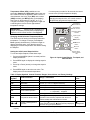
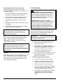
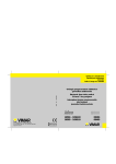
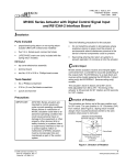
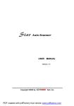
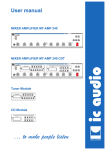
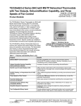
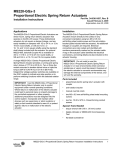
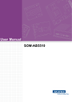
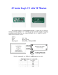
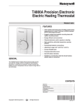
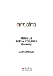
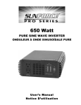
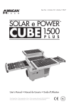
Installation Instructions
Issue Date April 21, 2014
A419ABG-3C Electronic Temperature Control
Application
IMPORTANT: Use this A419ABG-3C Electronic
Temperature Control only as an operating control.
Where failure or malfunction of the electronic
temperature control could lead to personal injury or
property damage to the controlled equipment or other
property, additional precautions must be designed
into the control system. Incorporate and maintain
other devices, such as supervisory or alarm systems
or safety or limit controls, intended to warn of or
protect against failure or malfunction of the electronic
temperature control.
IMPORTANT : Utiliser ce A419ABG-3C Electronic
Temperature Control uniquement en tant que
dispositif de contrôle de fonctionnement. Lorsqu'une
défaillance ou un dysfonctionnement du electronic
temperature control risque de provoquer des
blessures ou d'endommager l'équipement contrôlé
ou un autre équipement, la conception du système
de contrôle doit intégrer des dispositifs de protection
supplémentaires. Veiller dans ce cas à intégrer de
façon permanente d'autres dispositifs, tels que des
systèmes de supervision ou d'alarme, ou des
dispositifs de sécurité ou de limitation, ayant une
fonction d'avertissement ou de protection en cas de
défaillance ou de dysfonctionnement du electronic
temperature control.
The A419 Electronic Temperature Control is a
single-stage, electronic temperature control. Pre-wired
cords with plug and receptacle ends are provided for
quick and simple installation.
The control features a lockable, three-button touchpad
for setup and adjustment and a Liquid Crystal Display
(LCD) which displays the sensed temperature and
other control functions. A front panel Light-Emitting
Diode (LED) indicates the output relay status. The
control has a setpoint range of -30 to 212°F
(-34 to 100°C) and is available in 120 VAC models.
See the Technical Specifications section.
The A419 control has heating and cooling modes with
adjustable setpoint and differential, an adjustable
anti-short cycle delay, and a temperature offset
(setback) function. The control provides remote
© 2014 Johnson Controls, Inc.
Part No. 24-7664-2543, Rev. A
sensing capability, and electronic accuracy in a
Type NEMA 1 high-impact plastic enclosure suitable
for surface or DIN rail mounting. The temperature
sensor supplied with the control is interchangeable
with compatible Johnson Controls/PENN® A99
temperature sensors.
FCC Compliance
This equipment has been tested and found to comply
with the limits for a Class A digital device pursuant to
Part 15 of the FCC Rules. These limits are designed to
provide reasonable protection against harmful
interference when the equipment is operated in a
commercial environment. This equipment generates,
uses, and can radiate radio frequency energy and, if
not installed and used in accordance with the
instruction manual, may cause harmful interference to
radio communications. Operation of this equipment in
a residential area is likely to cause harmful
interference, in which case the user will be required to
correct the interference at his/her own expense.
Canadian DOC Compliance
This digital apparatus does not exceed the Class A
limits for radio noise emissions from digital apparatus
set out in the Radio Interference Regulations of the
Canadian Department of Communications.
Installation
Refer to the following guidelines, procedures and
illustrations when installing an A419 control.
Parts Included
Pre-wired cords with plug and receptacle ends are
provided for quick and simple installation.
Each A419 control includes a Johnson Controls/PENN
A99 temperature sensor. The sensor may be removed
and replaced with any compatible Johnson Controls®
A99 temperature sensor, or the wire leads on the
sensor may be extended.
See the Mounting and Wiring sections for additional
guidelines and restrictions when mounting and wiring
the control.
1
www.johnsoncontrols.com
Dimensions
9/64
(3.7)
1/2
(13)
DIN
Rail
2-15/16
(75)
Observe the following guidelines and refer to Figure 2
and Table 1 when wiring the sensor to the
A419 control.
2-3/8
(61)
2-3/8
(61)
5
(127)
MENU
•
Wire insulation rating must be 90°C, minimum.
•
Temperature sensor signals may be affected by
electrical interference. When extending sensor
cable beyond 50 ft (15.2 m), use a twisted-pair,
shielded cable to reduce electrical interference.
•
A99 temperature sensors are not polarity
sensitive. Wire the leads to (+) SEN and (-) COM
on the sensor terminal block (TB3). See Figure 2.
Keep the leads between the control and sensor as
short as possible/practical in your application. The
additional resistance in long sensor leads creates
error between the actual temperature and the
displayed temperature. Refer to Table 1 when
extending sensor leads.
4
(102)
1-9/16
(40)
7/16
(11)
6 ft (1.8 m)
Electrical Cords with
Male and Female Plugs
Sensor
2
(50)
1/4
(6)
Sensor
Wire Lead
6.6 ft
(2 m)
Table 1: Maximum Recommended Sensor Cable
Lengths and Wire Sizes
Wire
Gauge
Maximum Sensor Cable Length*
feet (meters)
Mounting
16 AWG
500 (150)
An A419 control has a standard high-impact plastic
NEMA 1 enclosure. The A419 control is not position
sensitive but should be mounted for convenient wiring
and adjustment.
18 AWG
300 (100)
20 AWG
200 (60)
22 AWG
125 (40)
At the listed maximum cable lengths, there is less
than 1F° (0.6C°) error in the actual temperature vs.
displayed temperature.
!
WARNING: Risk of Electric Shock.
Disconnect or isolate all power supplies before
making electrical connections. More than one
disconnection or isolation may be required to
completely de-energize equipment. Contact with
components carrying hazardous voltage can cause
electric shock and may result in severe personal
injury or death.
AVERTISSEMENT : Risque de décharge
électrique. Débrancher ou isoler toute alimentation
avant de réaliser un branchement électrique.
Plusieurs isolations et débranchements sont
peut-être nécessaires pour -couper entièrement
l'alimentation de l'équipement. Tout contact avec
des composants conducteurs de tensions
dangereuses risque d'entraîner une décharge
électrique et de provoquer des blessures graves,
voire mortelles.
(Optional)
Binary
Input
Switch
A419ABG-3
(+) BIN
(–) COM
(+) SEN
TB3
Cable
Shield
(if used)
A99
Sensor
TB1
TB2
Not
Used
120 VAC
Neutral
Not
Used
Load
Figure 2: Typical 120 VAC Application Wiring
All wiring must conform to the National Electrical Code
and local regulations.
2
120 VAC Application
C
NO
Wiring
*
AC COM
120
Figure 1: Dimensions, in. (mm)
A419ABG-3 Electronic Temperature Control Installation Instructions
AC
COM
Not
Used 120
TB1
Male
Plug
NO
Not
Used C
TB2
Female
Receptacle
Figure 3: Factory Power Wiring
Setup and Adjustments
!
WARNING: Risk of Electric Shock.
Disconnect or isolate all power supplies before
making electrical connections. More than one
disconnection or isolation may be required to
completely de-energize equipment. Contact with
components carrying hazardous voltage can cause
electric shock and may result in severe personal
injury or death.
AVERTISSEMENT : Risque de décharge
électrique. Débrancher ou isoler toute alimentation
avant de réaliser un branchement électrique.
Plusieurs isolations et débranchements sont
peut-être nécessaires pour -couper entièrement
l'alimentation de l'équipement. Tout contact avec
des composants conducteurs de tensions
dangereuses risque d'entraîner une décharge
électrique et de provoquer des blessures graves,
voire mortelles.
IMPORTANT:
To ensure that the output relay
operates as intended, verify that all three of the
jumpers are positioned properly for the application
before powering the A419 control.
IMPORTANT:
The touchpad cannot be
unlocked without a jumper installed across the
P5 jumper pins. Do not discard jumpers in case they
are required in the future. See Figure 4 and
Figure 5.
Positioning the Jumpers
The P5 jumper position determines if the touchpad is
locked or unlocked.
The P4 jumper pin block has two pairs of jumper pins.
The top pair of pins (JUMP1) determines if the control
is set for Heating or Cooling mode. The bottom pair of
pins, (JUMP2) establishes whether Setpoint is at cut-in
or at cutout. See Table 2 and Figure 5.
A419ABG-3 Electronic Temperature Control Installation Instructions
3
To position a jumper in the Installed position, place
the jumper on both pins, which closes the circuit
between the pins. To position a jumper in the
Removed position, place the jumper on one pin only.
See Figure 4.
=
Jumper
Installed
(Jumper Positioned on Both Pins)
=
Pins
Removed
(Jumper Positioned on One Pin)
Figure 4: Positioning the Jumpers
Touchpad
Locked
Heating Mode
Cut-in at Setpoint
Cooling Mode
Cut-in at Setpoint
JUMP2
P5
P4
Heating Mode
Cut-out at Setpoint
Cooling Mode
Cut-out at Setpoint
The A419 Control Functions
Setpoint (SP) establishes the temperature value at
which the equipment is switched on or off, depending
on the user selected mode of operation. Setpoint
range is -30 to 212°F or -34 to 100°C (in 1-degree
increments).
If Setpoint mode is set to cut-in, setpoint is the
temperature value at which the control closes the
Normally Open (N.O.) contacts. If Setpoint mode is set
to cutout, setpoint is the temperature at which the N.O.
contacts open.
Differential (dIF) establishes the difference in
temperature between the cut-in value and cutout
value. The differential is set relative to Setpoint and
may be set from 1 to 30 F° or C° (in 1-degree
increments).
Anti-Short Cycle Delay (ASd) establishes the
minimum time that the output relay remains
de-energized before the next on-cycle. The ASd does
not allow the output relay to re-energize until the
programmed time delay has elapsed. The delay is
activated when the control is first turned on and every
time an on-cycle ends. When the delay is activated,
the LCD alternately flashes the sensor temperature
and ASd. The Anti-short Cycle Delay range is
0 to 12 minutes (in 1-minute increments).
Sensor Failure Operation (SF) establishes how the
A419 control’s output-relay operates the equipment in
the event of a sensor or sensor wiring failure. The user
may select to run the equipment continuously or to
shut it down. When the control detects a sensor circuit
failure, the LCD flashes SF alternately with OP (if the
sensor circuit is open), or SH (if the sensor circuit is
shorted). Before indicating a failure, the control
implements a 1-minute delay, which allows verification
of failure condition and avoids nuisance failure
indications.
Figure 5: Jumper Positions and Control Settings
Table 2: Jumper Designations, Jumper Positions, and Control Settings
Function
4
Jumper Pins Designation
on Control
Cooling/Heating
Operating Mode
JUMP1
(Top Pair of Pins on Block P4)
Setpoint at
Cut-in or Cutout
JUMP2
(Bottom Pair of Pins on Block P4)
Touchpad Lock
P5
Setting
Jumper
Position
Cooling Mode
Removed
Heating Mode
Installed
Setpoint
at Cut-in
Removed
Setpoint
at Cutout
Installed
Locked
Removed
A419ABG-3 Electronic Temperature Control Installation Instructions
Factory Default Setting
(and Jumper Position)
Cooling Mode
(Jumper Removed)
Cut-in
(Jumper Removed)
Unlocked
(Jumper Installed)
Temperature Offset (OFS) establishes a set
secondary Setpoint and Differential values that may
be invoked to control an application when a circuit is
closed between the binary input (BIN) and common
(COM) terminals (and BIN appears on the display).
See Figure 6. Offset range is 0 to 50F° or C° (in
1-degree increments). A typical application might use
a switching time clock to invoke night-setback
temperature settings.
If no setup entry is made for 30 seconds, the control
reverts to the (normal) temperature display.
IMPORTANT: If MENU is not pressed after
changing the setpoint value, the control reverts to
the previously programmed setpoint value.
Temperature
Offset Indicator
BIN
IMPORTANT:
Make sure the Touchpad Lock
jumper is installed (unlocked) before attempting to
adjust the A419 control functions. See Figure 5.
F
Operating Mode
Indicator
Liquid Crystal
Display
Changing the A419 Control Temperature Units
The A419 control is factory set to display Fahrenheit
temperature. To change to Celsius, press Up and
Down (arrows) simultaneously. Press them again to
display Fahrenheit units. Verify that the control is
displaying the desired temperature units before setting
the Setpoint.
MENU
MENU Button
DOWN Arrow
Button
UP Arrow
Button
Setting the A419 Control Setpoint Value
To view and adjust Setpoint, follow these steps:
1. Press and hold MENU (about 2 seconds) until the
display flashes SP.
Temperature
Units Indicator
Output Relay
Status Indicator
LED
Figure 6: Liquid Crystal Display, Touchpad, and
LED Indicator
2. Press MENU again to display the existing setpoint
value.
3. Press Up or Down (arrows) to change the setpoint
value.
4. Press MENU again to save the new value. The
display returns to the sensed temperature.
Table 3: Display Symbols, Control Function, Ranges, Units, Values, and Factory Settings
Display
Symbol
SP
Control Function
Range – Units/Value
Factory Set
Value
Setpoint*
-30 to 212 – °F (-34 to 100 – °C)
30
dIF
Differential*
1 to 30 – (F° or C° in 1-degree increments)
5
ASd
Anti-short Cycle Delay
0 to 12 – (in 1-minute increments)
1
OFS
Temperature Offset
0 to 50 (F° or C° in 1-degree increments)
0
SF
Sensor Failure Operation
F or C
Temperature Units
(No range) – F° or C°
F°
Temperature Offset Indicator
(No range) – BIN is displayed and the A419 control
operates on the secondary setpoints when the circuit
between the BIN and COM terminals is closed.
N/A
Cooling or Heating Mode of
Operation
(Cooling Mode) is displayed when the
(No range) –
Jump1 jumper is removed. (Heating Mode) is displayed
when the Jump1 jumper is installed.
Cooling Mode
BIN
or
*
(No range) –
0 = output relay
1 = output relay
de-energized
energized
1
The sum of the Setpoint and Differential values must be within the Setpoint range, or the control may not function
properly.
A419ABG-3 Electronic Temperature Control Installation Instructions
5
Setting the Other A419 Control Functions
To set the Differential, Anti-short Cycle Delay,
Temperature Offset, or Sensor Failure operation, use
the following method:
1. Press and hold MENU until the display changes to
flashing SP. (This takes about 2 seconds.)
2. Press Up or Down (arrows) repeatedly until the
desired function is displayed. (See Figure 6.)
3. Press MENU to display the function’s current
value.
4. Press Up or Down (arrows) until the desired value
is displayed.
5. Press MENU to save the new value. The display
returns to the sensor temperature.
IMPORTANT:
If MENU is not pressed after
changing the settings, the new settings are not
saved and the control reverts to the previously
programmed setting values.
Note: If no setup entry is made for 30 seconds, the
control reverts to the (normal) temperature display.
Note: Any saved A419 control settings are
non-volatile and remain in the control’s memory
during power interruptions.
IMPORTANT:
Do not set Setpoint and
Differential values which (when totaled) fall out of
A419 control’s Setpoint range (-30 to 212°F
[-34 to 100°C]). The control will not function properly
if Cut-in or Cutout values are outside of the control’s
Setpoint range.
Checkout
Before applying power, make sure installation and wire
connections are correct for your application. Then
power, operate, and observe the system and A419
control for at least three complete operating cycles
before leaving the installation.
6
Troubleshooting
!
WARNING: Risk of Electric Shock.
Do not touch any exposed metal parts with anything
other than properly insulated tools or insulated
probes of the digital voltage meter. Failure to use
properly insulated tools and probes may result in
severe personal injuries or death.
AVERTISSEMENT : Risque de décharge
électrique. Ne jamais toucher une partie métallique
exposée avec tout élément autre que des outils
correctement isolés ou les sondes isolées du
voltmètre numérique. L'utilisation d'outils et de
sondes incorrectement isolés risque de provoquer
des blessures graves, voire mortelles.
If the control system does not function properly, verify
that the control is wired, and set up properly. If the
problem persists, use the following procedures to
determine the cause of the problem:
IMPORTANT:
Follow these troubleshooting
procedures in the order presented. Do not skip any
of the steps in the procedures.
1. Check for proper voltage to the A419 control.
a. Remove the cover by loosening the four
captive cover screws.
b. Use a reliable AC voltmeter to check the
voltage between the COM and 120V terminals
on terminal block TB1. Refer to Figure 2.
c. The voltage must be between 102 and
132 VAC for 120 VAC applications.
d. If the voltage reading is not within the required
range, check the power source and input
power wires for problems.
2. Check for proper sensor operation.
a.
Disconnect all power sources to control.
b.
Using an accurate thermometer, take a
temperature reading at the sensor location.
c.
Disconnect the sensor from the control.
d.
Using an ohmmeter, measure the resistance
across the two sensor leads while the sensor
is at the temperature taken in Step 2b.
e.
Consult Figure 7 to verify that the measured
temperature and resistance conform to
established temperature and resistance
values.
A419ABG-3 Electronic Temperature Control Installation Instructions
f.
If the measured values conform to the values
in Figure 7, proceed to Step 3.
b.
Ensure that the Touchpad Lock jumper is
installed, so that the touchpad is unlocked.
g.
If the sensor’s measured resistance value is
substantially different from the expected
value for that temperature, check the sensor
wiring. If sensor wiring is okay, replace the
sensor.
c.
Reconnect the sensor leads and supply
power to the control.
d.
Replace the cover.
e.
Check the control settings for proper values.
f.
Press and hold MENU until Setpoint
appears. (This takes about 2 seconds.)
g.
Press the Up and Down (arrows) to change
the Setpoint temperature above and below
the sensor temperature until the relay
energizes and de-energizes as shown in
Figure 7.
Temperature (°F)
260
240
220
200
180
160
140
120
100
80
60
40
20
0
-20
-40
500
Temperature (°C)
120
100
80
60
40
20
0
-20
-40
700 900 1100 1300 1500 1700 1900 2100
Note: If the anti-short cycle delay has a set
delay-time value greater than 0 minutes when the
control is powered On, the relay does not energize
until the time delay has elapsed.
h. If the output relay does not perform as
indicated in Figure 7, replace the A419 control.
Resistance in Ohms
i.
Figure 7: Temperature vs. Sensor Resistance
3. Check the A419 for proper operation.
Note: Perform Troubleshooting Steps 1 and 2 before
performing this step.
a.
Disconnect the load from the output relay
terminals.
If proper operation of the A419 control is
verified, reconnect the load and consult the
equipment manufacturer’s instructions for
troubleshooting the controlled equipment.
Fault Codes
If the LCD displays an alarm or fault code (SF or EE),
consult Table 5 for explanation.
Table 4: A419 Output Relay Operation in Different Operating Modes
Setpoint
Mode
Cutout
Cut-in
Operating
Mode
Output Relay Is Energized (closing
the NO and COM contacts) at…
Output Relay Is De-Energized (opening
the NO and COM contacts) at…
Cooling
Setpoint plus differential
Setpoint
Heating
Setpoint minus differential
Setpoint
Cooling
Setpoint
Setpoint minus differential
Heating
Setpoint
Setpoint plus differential
Table 5: Fault Codes Defined
Fault Code
Definition
System Status
Solution
SF flashing alternately
with OP
Open temperature
sensor or sensor wiring
Output functions according to
the selected sensor failure mode
(SF setting)
See Troubleshooting section.
Cycle power to reset the control.
SF flashing alternately
with SH
Shorted temperature
sensor or sensor wiring
Output functions according to
the selected sensor failure mode
(SF setting)
See Troubleshooting section.
Cycle power to reset the control.
EE
Program failure
Output is off
Reset the control by pressing
MENU. If problems persist, replace
the control.
A419ABG-3 Electronic Temperature Control Installation Instructions
7
Repairs and Replacement
Ordering Information
Do not attempt to repair or recalibrate the
A419 temperature control. In case of a defective or
improperly functioning control, contact your nearest
Authorized Johnson Controls/PENN distributor or
sales representative.
Refer to Table 6 to order sensors, mounting hardware
and other accessories used to install A419 controls.
Contact your nearest Johnson Controls/PENN
distributor or sales representative to order these
products.
When contacting your Johnson Controls/PENN
distributor, have the model number of the control
available. This number can be found on the label
inside the cover of the control.
Table 6: A419 Controls Accessories
Product Code Number
Description
A99BB-200
Temperature Sensor: PTC Sensor with 6-1/2 ft (2 m) Non-shielded 2-Wire Lead
BKT287-1R
BKT287-2R
PLT344-1R
DIN Rail: 12 in. (305 mm) long
DIN Rail: 36 in. (914 mm) long
End Clamps for DIN Rail Mounting
CLK350-2C
7-Day Programmable Digital Clock for activating Binary Offset
WEL11A-601C
Immersion Well for Mounting Sensor in Liquid Applications
Technical Specifications
Product
Setpoint Range
Differential Range
Supply Voltage
Power Consumption
SPST Output Relay
Contacts Electrical
Ratings
Sensor Type
Control Ambient
Temperature
Ambient Humidity
Control Enclosure Material
Agency Listings
A419ABG-3C Electronic Temperature Control
-30 to 212°F (-34 to 100°C)
1 to 30F° (1 to 30C°)
120 VAC, 60 Hz
1.8 VA Maximum
Full Load Amperes N.O.:
Locked Rotor Amperes N.O. :
Non-inductive Amperes N.O.:
12 A
72 A
10 A
Pilot Duty:
125 VA @ 120 VAC
PTC Sensor with 6.6 ft (2.0 m) leads
Operating:
-30 to 140°F (-34 to 60°C)
Shipping:
-40 to 185°F (-40 to 85°C)
0 to 95% RH Noncondensing; Maximum Dew Point: 85°F (29°C)
Case and Cover:
NEMA 1 - High-Impact Thermoplastic
UL: File E27734; CCN’s XAPX (US), XAPX7 (Canada)
FCC: CFR 47, Part 15, Class A. DOC, Class A
The performance specifications are nominal and conform to acceptable industry standards. For application at conditions beyond these
specifications, contact Application Engineering at 1-800-275-5676. Johnson Controls, Inc. shall not be liable for damages resulting from
misapplication or misuse of its products.
Building Efficiency
507 E. Michigan Street, Milwaukee, WI 53202
® Johnson Controls and PENN are registered trademarks of Johnson Controls, Inc. in the
United States of America and/or other countries. All other trademarks used herein are the property
of their respective owners. © Copyright 2014 by Johnson Controls, Inc. All rights reserved.
8
A419ABG-3 Electronic Temperature Control Installation Instructions