1
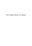
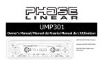
CD6112
CD6112
Instruction Manual
CD6112
TABLE OF CONTENTS
Table of Contents ......................................................................................i
Introduction ..............................................................................................1
Installation ................................................................................................2
Wiring Diagram ........................................................................................4
Front Panel Release ................................................................................5
Operation .................................................................................................6
Tuner Operation .......................................................................................8
CD Player Operation ................................................................................9
Remote Control ......................................................................................10
Care and Maintenance ...........................................................................11
Troubleshooting .....................................................................................12
Specifications .........................................................................................13
i
CD6112
ii
CD6112
INTRODUCTION
Congratulations on your purchase of the Jensen CD6112 Mobile Receiver.
It’s a good idea to read all of the instructions before beginning the
installation. We recommend having your Jensen CD6112 installed by a
reputable installation shop.
Features
CD
•
CD R / RW Compatible
•
Last Position Memory
•
Audible Forward / Reverse Track Search
•
Random, Repeat and Intro
•
Play, Pause, Stop, Next Track and Previous Track
AM-FM
•
USA / Europe Frequency Spacing
•
30 Station Presets (18 FM / 12 AM)
•
Stereo / Mono
•
Local / Distance
•
Auto Store / Preview Scan
Chassis
•
Detachable Faceplate
•
1.0 DIN (Import / ISO-DIN Mountable)
•
8 Character / Segment Type LCD Display
•
Chassis Mounted Rear Auxiliary Inputs
General
•
•
•
•
•
•
•
•
•
•
Infrared Remote Control
Media Adapter Cable (2 meter male 3.5mm to male RCA cable)
Programmable Volume Control
Three Preset EQ Curves
Loudness
Rotary Encoder Audio Control
Beep Tone Confirmation (On-OFF Option)
Rear Line Output
200-Ohm Preamp Line Outputs
2VRMS Line Outputs
1
CD6112
INSTALLATION
Using the Mounting Sleeve
1. Slide the mounting sleeve off the chassis. If it is locked into position,
use the removal tools (supplied) to disengage it.
2. Check the dashboard opening size by sliding the mounting sleeve into
it.
This unit is designed for installation in cars, trucks and vans with an existing
radio opening. In many cases, a special installation kit will be required to
mount the radio to the dashboard. These kits are available at electronics
supply stores and car stereo specialty shops. Always check the kit
application before purchasing to make sure the kit works with your vehicle.
If you have trouble locating a kit or need installation assistance, contact
Technical Support at 1-800-323-4815 from 9:00am to 6:00pm EST Monday
through Friday.
Tools and Supplies
The following tools and supplies are needed to install the radio:
•
Torx type, flathead and Philips screwdrivers
•
Wire cutters and strippers
•
Tools to remove existing radio (screwdriver, socket wrench set or other
tools)
•
Electrical tape
•
Crimping tool
•
Volt meter/test light
•
Crimp connections
•
18 gauge wire for power connections
•
16-18 gauge speaker wire
3.
Preparation
1. Disconnect Battery
Before you begin, always disconnect the battery negative terminal.
2. Remove Transport Screws
CAUTION: For proper operation of the CD player, the chassis must be
mounted within 20° of horizontal. Make sure the unit is mounted within
this limitation.
4.
TRANSPORT
SCREWS
HALF
SLEEVE
5.
CD6
112
MOSFET
POWERED
/
LO/DX
LOUD
PS/AS
DN
UP
6.
3.
If the opening is too small, carefully cut or file as necessary until the
sleeve easily slides into the opening. Do not force the sleeve into the
opening or cause it to bend or bow. Check for sufficient space behind
the dashboard for the radio chassis.
Locate the series of bend tabs along the top, bottom, and sides of the
mounting sleeve. With the sleeve fully inserted into the dashboard
opening, bend as many of the tabs outward as necessary to firmly
secure the sleeve to the dashboard.
Remove Radio from Sleeve
Lift latches on both sides of sleeve to remove half-sleeve from radio.
2
Place the radio in front of the dashboard opening so the wiring can be
brought through the mounting sleeve. Follow the wiring diagram
carefully and make certain all connections are secure and insulated
with wire nuts or electrical tape. See “Wiring Diagram” on page 4.After
completing the wiring connections, turn the unit on to confirm operation
(vehicle ignition must be on). If the unit does not operate, re-check all
wiring until the problem is corrected.
Make sure the radio is right-side up, then
SPRING CLIP
carefully slide the radio into the mounting
sleeve until it is fully seated and the spring clips
lock it into place.
Secure the rear of the unit to the car body
using the mounting bolt and rubber cushion.
CD6112
7.
Test the radio using the Operating Instructions that follow.
2.
3.
BEND TABS
MOUNTING
SLEEVE
RUBBER
CUSHION
4.
5.
MOUNTING BOLT
Carefully unsnap the plastic frame from the front of the new radio
chassis. Remove and discard the frame.
Remove the factory mounting brackets and hardware from the existing
radio and attach them to the new radio. Do not exceed M5 x 9 MM
maximum screw size. Longer screws may damage components inside
the chassis.
Wire the new radio to the vehicle as outlined in the Universal Installation
instructions.
Mount the new radio assembly to the dashboard or center console
using the reverse procedure of step 1.
Fuses
When replacing a fuse, make sure the new fuse is the correct type and
amperage. Using an incorrect fuse could damage the radio.
RADIO
Reconnect Battery
When wiring is complete, reconnect the battery negative terminal.
TRIM RING
Removing the Radio
To remove the radio after installation, remove the trim ring by lifting in the
center and pulling it off from either side. Insert the removal keys straight
back until they lock, then pull the radio out. If removal keys are inserted at
an angle, they will not lock properly and will not release the unit.
Kit Installation
If your vehicle requires the use of an installation kit to mount this radio,
follow the instructions included with the installation kit to attach the radio to
the mounting plate supplied with the kit.
1. Wire and test the radio as outlined in the Universal Installation instructions.
2. Install the radio/mounting plate assembly to the sub-dashboard
according to the instructions in the installation kit.
3. Attach the support strap to the radio and dashboard as described in the
Universal Installation instructions.
4. Replace the dashboard trim panel.
ISO Installation
This unit has threaded holes in the chassis
side panels which may be used with the
original factory mounting brackets of some
vehicles to mount the radio to the
dashboard. Please consult with your local
car stereo shop for assistance on this type
of installation.
1. Remove the existing factory radio
from the dashboard or center console
mounting. Save all hardware and
brackets as they will be used to mount the new radio.
Technical Assistance
If you require assistance, contact Technical Support at 1-800-323-4815
from 9:00am to 6:00pm EST Monday through Friday.
3
CD6112
WIRING DIAGRAM
Antenna
Connect the antenna plug
from the existing antenna
cable (some vehicles
require an adaptor).
R (Red)
L (White)
Fuse (15 amp fast blow ATO)
Aux-in
Ground
Connect to ground terminal
or clean, unpainted part
of chassis.
Memory/Battery
Connect to battery or 12 volt
power source that is always live.
The radio will not work if this
wire is not connected.
R (Red)
Gray
L (White)
Black
Blue
Power Antenna
Connect to power antenna or amplifier.
If not used, tape bare end of wire.
Yellow
Red
Accessory/Ignition
Connect to existing radio wire
or radio fuse.
FRONT SP
White/Black
Stripe
Rear Line out
White
Left Speaker
(Front)
Gray/Black
Stripe
Gray
REAR SP
Green/Black
Stripe
Right Speaker
(Front)
Green Purple/Black
Stripe
Left Speaker
(Rear)
Purple
Right Speaker
(Rear)
NOTE: Only connect speakers rated in the load impedance of 4 ohms.
Speakers with a load impedance less than 4 ohms could damage the
unit.
NOTE: The amplifier in this radio is only designed for use with four
speakers. Never combine (bridge) outputs for use with two speakers.
Never ground negative speaker leads to chassis ground. Failure to
wire exactly as shown may cause electrical damage to the radio.
4
CD6112
FRONT PANEL RELEASE
The front panel release button (4) releases the mechanism that holds the
front panel to the chassis.
Detaching the Front Panel
To detach the front panel, first press the front panel release button to
release the left side of the panel. Next, grasp the released side and pull it off
the chassis. After removing the front panel, store it in the supplied carrying
case to protect it from dirt and damage.
Re-attaching the Front Panel
To re-attach the front panel, make sure the electrical terminals on the back
of the panel are free of dust and dirt, as debris could cause intermittent
operation or other malfunctions. Position the right side of the panel in place
so that it is correctly engaged, then lightly press the left side of the panel
until the mechanism locks it into place.
5
CD6112
OPERATION
Power
Press the power button (2) to turn the unit on. Press and hold the power
button again to turn the unit off.
NOTE: LCD panels may take longer to respond when subjected to cold
temperatures for an extended period of time. In addition, the visibility
of the numbers on the LCD may decrease slightly. The LCD display
will return to normal when the temperature increases to a normal
range.
CD6112
160
Watts
/
DX/ST
LOUD
PS/AS
Source
Press the SRC button (6) to select a different mode of operation, as
indicated on the display panel. Available modes include tuner (FM1, FM2,
FM3, AM1, AM2), CD, and auxiliary (AUX). CD mode appears in the menu
only if a CD is present in the CD player.
Audio Mute
Press the mute button (2) to silence the audio volume. “Mute” appears on
the display. Press mute again to restore volume to the previous setting.
Bass
To adjust the bass level from “-6” to “+6”, press the MENU button (5) until
“BAS” appears in the display. Turn the rotary encoder clockwise to increase
or counter-clockwise to decrease the bass. “0” represents a flat response.
Treble
Volume / Audio Control
To increase the volume, turn the rotary encoder (5) clockwise. To decrease
the volume, turn the rotary encoder counter-clockwise. When volume is
adjusted, the volume level will be shown on the display panel as a number
ranging from “0” (lowest) to “46” (highest).
Press the MENU button (5) repeatedly to step through the following audio
functions: volume (VOL), bass (BAS), treble (TRE), balance (BAL), fader
(FAD) and back to volume. The unit automatically exits audio control mode
after five seconds of inactivity.
To adjust the treble level from “-6” to “+6”, press the MENU button until
“TRE” appears in the display. Turn the rotary encoder clockwise to increase
or counter-clockwise to decrease the treble. “0” represents a flat response.
Balance
To adjust the balance from “12L” (full left) to ”12R” (full right), press the
MENU button until “BAL” appears in the display. Turn the rotary encoder to
adjust the balance between the left and right speakers. “L = R” represents a
center balance.
Fader
VOL
To adjust the fader from “12F” (full front) to “12R” (full rear), press the
MENU button until “FAD” appears in the display. Turn the rotary encoder to
adjust the fader between the front and rear speakers. “F = R” represents a
center fader level.
E
TR
FAD
BA
L
BA
VOL
S
P U S H S EL E C
T
BAS
FAD
BA
E
TR
E
TR
FAD
BA
BA
P U S H S EL E C
S
E
TR
FAD
BA
L
BA
T
T
P U S H S EL E C
P U S H S EL E C
BAL
S
L
S
L
BA
FAD
TRE
T
6
CD6112
Equalizer Selector
The equalizer function applies preset sound effects to the unit’s audio
output signal. Press EQ (16) to step through the following equalizer options:
“ROCK”, “HIP-HOP”, “DANCE”, and “EQ OFF”.
When the equalizer function is activated, the most recently selected bass/
treble levels cannot be adjusted. When the equalizer function is not active,
the unit will return to the most recently selected bass and treble levels.
Clock Set
1. Press the DISP button (7) to display the clock.
2. Press and hold the DISP button until the clock blinks.
3. Turn the rotary encoder (5) clockwise the set the hour and counterclockwise to set the minutes.
Reset Button
The RESET button is located on the front of the chassis and can only be
accessed with the front panel removed. The reset circuitry protects the
microprocessor circuitry. Since resetting the unit will erase the time and
preset memories, it should only be activated upon initial installation after all
wiring is complete or if there is a malfunction of any of the switches on the
unit. In these circumstances, pressing the RESET button will clear the
system and return the unit to normal operation.
Loudness Control (LOUD)
When listening to music at low volume levels, this feature will boost the
bass and treble ranges to compensate for the characteristics of human
hearing. Press the LOUD button (14) to turn the LOUD function on/off.
Menu Operation
Press and hold the MENU button (5) for more than two seconds to access
the menu. Press the MENU button to move through the following menu
options: VOL LAST/VOL ADJ, BEEP ON/OFF, AREA SET MODE, 12/24
HOUR SET MODE.
Programmable Turn-on Volume Level
RESET
RESET BUTTON
Press the MENU button (5) to select “VOL LAST” or “VOL ADJ”.
•
VOL LAST: When the unit is turned on, the volume will resume at the
level selected when last turned off.
•
VOL ADJ: After selecting “VOL ADJ”, turn the rotary encoder (5) to
select the desired level. When this option is selected, the unit will revert
to the adjusted volume each time the unit is turned on.
Beep Tone
The beep tone feature allows the selection of an audible beep tone to be
heard each time a button is pressed on the face of the radio. “BEEP ON” is
the default display.
To turn the audible beep off:
1. Press the MENU button to select “BEEP ON”.
2. Turn the rotary encoder to select the “BEEP OFF” option.
Frequency Spacing
This option allows you to select the appropriate frequency spacing for your
area. “AREA U.S.A.” is the default setting. Turn the rotary encoder to select
“EUROPE”.
12/24 Hour Time Format
This option allows selection of a 12 hour or 24 hour clock format. “12
HOUR” is the default setting. Turn the rotary encoder to change to the 24
hour clock format.
7
CD6112
TUNER OPERATION
The CD6112 allows you to receive channels in U.S.A. or EUROPE mode.
See “Frequency Spacing” on page 7 to learn how to change the tuner
options.
Auto Seek Tuning
Press the UP TUNING >>| or DOWN TUNING |<< buttons (17) for less than
three seconds to move to the next/previous station automatically.
Preset Stations
Up to six stations on each band can be stored as presets and can then be
instantly recalled by pressing the associated preset button (12). To store a
station, turn the radio on and select the desired band and station. Press and
hold the desired preset button (numbered one through six on the face of the
radio) for more than two seconds. When stored, the preset number will
appear in the display. The station is now stored and can be re-called at any
time by pressing the corresponding preset button. Repeat for the remaining
five presets on the current band and for all presets on the other four bands.
CD6112
160
Watts
/
DX/ST
LOUD
PS/AS
Preview Scan / Automatically Store (PS/AS)
Preview Scan
Press PS/AS (13) to scan all strong stations in the current band. The unit
will stop at each station for five seconds before continuing to the next
station. Press PS/AS again to stop scanning and listen to the current
station.
Automatically Store
Select a Band
Press BAND (3) to change between three FM bands and two AM bands.
Each band stores up to six preset stations.
Select six strong stations and store them in the current band using the
Automatic Store feature. To enable this feature, press and hold PS/AS (13)
for more than two seconds. The radio will automatically scan the band in
use and enter strong stations into the preset memory positions for that
band. After entering the stations into memory, the unit will automatically
stop at each station for five seconds so each can be heard. When using the
Automatically Store feature, the new stations replace any stations already
stored in preset memory for the selected band.
Mono/Stereo Selection
Press and hold the DX/ST button (15) to switch between monaural and
stereo reception. Choose mono when a strong stereo signal cannot be
achieved (stereo mode is indicated by the
icon). “MONO” or “STEREO”
temporarily appears on the screen when selected.
Local/Distant Reception
When the Local function is on, only radio stations with a strong radio signal
are played. Activate the Local (LOC) function by pressing the DX/ST button
(15). Press DX/ST again to activate the Distant (DX) mode (indicated by the
triangle with rings above it).
Tuning
Manual Tuning
Press the UP TUNING >>| or DOWN TUNING |<< buttons (17) for more
than three seconds to enter manual tuning mode, then press the Up Tuning
or Down Tuning buttons to move the radio frequency number up or down
one step.
8
CD6112
CD PLAYER OPERATION
Insert and Eject CD
Insert a CD, label side up. To stop CD play and eject the CD, press the eject
button (1).
NOTE: The unit is designed for play of standard 5” (12 cm.) compact
discs only. Do not attempt to use 3” (8 cm.) CD singles in this unit,
either with or without an adaptor, as damage to the player and/or the
disc may occur. Such damage will not be covered by the warranty on
this product.
CD6112
160
Watts
/
DX/ST
LOUD
PS/AS
Pause
Press the pause >/|| button (8) to suspend disc play. Press the pause button
again to resume disc play.
Track Select
Press the UP TUNING >>| or DOWN TUNING |<< buttons (17) for less than
one second to advance to the next track on the CD. The selected track
number will appear on the display. Press and hold the UP TUNING >>| or
DOWN TUNING |<< buttons (17) to fast forward or fast reverse through the
disc. CD play starts when the button is released.
CD Player Error Codes
If a problem should develop while operating the CD player, an error code
(ER-1, ER-2, etc.) may appear on the display panel. This can indicate a
number of problems with the unit, including a mechanical error or an error in
the microprocessor control of the player. If an error code should appear, try
ejecting and reloading the disc into the player. While the disc is out of the
unit, make sure it is clean and undamaged, and then load it correctly. If this
does not solve the problem, pressing the RESET button may help, but will
erase the time and preset memory. If the suggested measures do not solve
the problem, contact an approved warranty station near you for further
assistance.
Intro Scan (INT)
During disc play, press INT (9) to play the first 10 seconds of each track on
the disc. When the desired track is reached, press INT again to end the
scan and play the selected track.
Repeat (RPT)
Press RPT (10) during disc play to continuously repeat the track. Press
RPT again to stop repeating.
NOTE: If an MP3 or other unsupported format disc is inserted in the
unit, 'Disc Error' appears on the LCD. This unit only supports the CDDA format.
Random (RDM)
Press RDM (11) during disc play to play all tracks on a CD in random,
shuffled order. Press RDM again to stop random play.
9
CD6112
REMOTE CONTROL
Replacing the Battery
When the range of operation of the card remote control becomes short or
stops functioning, replace the battery with a new lithium battery. Be sure to
observe the proper polarity, as indicated below.
The remote control will allow you to control the basic functions of the
CD6112.
(CR 2025)
MUTE
SRC
VOL
SEL
PS/AS
MENU
LOUD
DX/ST
EQ
1
BAND
1
2
3
4
/
INT
RPT
RDM
5
6
DISP
Operating Range
The remote control sensor (19) is located to the right of the SRC button.
The remote control can operate within a distance of 3~5m.
REMOTE SENSOR
10
2
CD6112
CARE AND MAINTENANCE
CD Player
The following guidelines will help you extend the life of your CD player:
1. When cleaning the vehicle interior, do not get water or cleaning fluids on
the unit.
2. DO NOT attempt to disassemble the unit. Laser beams from the optical
pickup are dangerous to the eyes.
3. The CD player may not operate properly in extreme hot/cold or under
damp conditions. In case of such conditions, wait until the vehicle
interior reaches a normal temperature or any condensation on the disc
player lens has evaporated before using the player.
4. Never insert anything other than round 5” CDs into the player.
Attempting to insert CDs of other sizes (even with an adaptor) will
cause damage not covered by the warranty.
5. Always remove the CD when the player is not is use.
6. The unit is designed with a vibration dampening CD mechanism to
minimize interruption of disc play due to normal vibration in a moving
vehicle. However, occasional sound skips may occur when driving on
very rough roads. This will not scratch or damage the disc, and normal
play will resume when the rough conditions cease.
2.
3.
4.
5.
6.
Compact Discs
CD-R and CD-RW Capability
Depending on media type and method of "recording/burning", some CD-R/
RWs may be incompatible with this unit. After "recording/burning", the
session must be closed. Please refer to your software's recommended
procedures for closing a disc/session. Review your recording software to
familiarize yourself with the correct "recording/burning" procedures. We
recommend using the latest versions of ROXIOTM or NEROTM burning
software.
In addition, this unit will only recognize the CDDA (Compact Disc Digital
Audio) format "recorded / burned" onto a CD-R/RW. This unit does not
support .MP3, .WMA, .WAV, .OGG or other formats.
CD Care and Handling
Dirt, dust, scratches and warpage can cause skips in the playback and
deterioration of sound quality. Please follow these guidelines to take care of
your compact discs.
1. Carefully wipe fingerprints, dust and dirt from the disc’s playing surface
with a soft cloth. Wipe in a straight motion from the inside to the outside
11
of the disc. Playing a defective or dusty CD can cause dropouts in
sound.
Never use chemicals such as record sprays or household cleaners to
clean CDs, as they can irreparably damage the disc’s surface.
This unit cannot play 3-inch ( 8cm ) CDs. NEVER insert a 3-inch CD
contained in the adapter or an irregularly shaped CD. The unit may not
be able to eject it, resulting in a malfunction.
Discs should be kept in their storage cases when not in use.
Do not expose discs to direct sunlight, high temperatures or high
humidity for long periods.
Do not stick paper, tape or CD labels on disc surfaces, as internal
damage may occur.
CD6112
TROUBLESHOOTING
Problem
Does not operate
(display does not
light)
No power to unit
Not all speakers
operate
Blows fuses
Cause
No power to yellow
wire; no power to red
wire
Inline fuse blown
Inline fuse blown
Incorrect splices or
connections
Speaker wires shorting
to chassis ground or to
each other
Power wire shorting to
ground
Speaker wires shorting
to ground
Incorrect fuse; fuse too
small
Corrective Action
Check connection with test
light; check vehicle fuse with
test light
Replace fuse
Check/replace fuse
Check all splices and
connections
Check splices; insulate all
bare wires
Make sure wire is not pinched
Make sure wire is not pinched
Install fuse of correct rating
12
CD6112
SPECIFICATIONS
CEA Power Ratings
Power Output . . . . . . . . . . . . . . . 13 Watts RMS x 4 channels into 4-Ohms @ < 1% THD+N
Signal to Noise Ratio
70dBA below reference (Reference: 1 Watt, 4-Ohms)
Frequency Response . . . . . . . . . . 20 Hz - 20 kHz, -3dB (Aux Input used as reference input)
Reference Supply Voltage. . . . . . . . . . . . . . . . . . . . . . . . . . . . . . . . . . . . . . . . . . . . . 14.4VDC
CD Player
Compatible Disc Media . . . . . . . . . . . . . . . . . . . . . . . . . . . . . . . . . . . . . . . . . . . . . CD-R / RW
Compatible Media Formats . . . . . . . . . . . . . . . . . . . . . . . . . . . . . . . . . . . . . . . . . . . . . CD-DA
Signal to Noise Ratio @ 1 kHz . . . . . . . . . . . . . . . . . . . . . . . . . . . . . . . . . . . . . . . . . . . >90dB
Frequency Response . . . . . . . . . . . . . . . . . . . . . . . . . . . . . . . . . . . . . . 20Hz to 20 kHz, -3dB
Channel Separation . . . . . . . . . . . . . . . . . . . . . . . . . . . . . . . . . . . . . . . . . . . > 60dB @ 1 kHz
D/A Converter . . . . . . . . . . . . . . . . . . . . . . . . . . . . . . . . . . . . . . . . . . . . . . . . . . . 1bit/ channel
FM Tuner
Tuning Range . . . . . . . . . . . . . . . . . . . . . . . . . . . . . . . . . . . . . . . . . . . . 87.5MHz - 107.9MHz
Mono Sensitivity (-30dB) . . . . . . . . . . . . . . . . . . . . . . . . . . . . . . . . . . . . . . . . . . . . . . . . 11dBf
Quieting Sensitivity (-50dB). . . . . . . . . . . . . . . . . . . . . . . . . . . . . . . . . . . . . . . . . . . . . . 15dBf
Signal to Noise Ratio @ 1 kHz . . . . . . . . . . . . . . . . . . . . . . . . . . . . . . . . . . . . . . . . . . . . 58dB
Stereo Separation @ 1 kHz. . . . . . . . . . . . . . . . . . . . . . . . . . . . . . . . . . . . . . . . . . . . . . >30dB
Frequency Response . . . . . . . . . . . . . . . . . . . . . . . . . . . . . . . . . . . . . . . 30Hz - 12kHz, -3dB
AM Tuner
Tuning Range . . . . . . . . . . . . . . . . . . . . . . . . . . . . . . . . . . . . . . . . . . . . . 530 kHz - 1710 kHz
Sensitivity (-20dB) . . . . . . . . . . . . . . . . . . . . . . . . . . . . . . . . . . . . . . . . . . . . . . . . . . . . . . 15uV
Signal to Noise Ratio @ 1 kHz . . . . . . . . . . . . . . . . . . . . . . . . . . . . . . . . . . . . . . . . . . . . 50dB
Frequency Response . . . . . . . . . . . . . . . . . . . . . . . . . . . . . . . . . . . . . . . . 50Hz - 2kHz, -3dB
Auxiliary Input
Input Sensitivity . . . . . . . . . . . . . . . . . . . . . . . . . . . .400mV RMS for 1 watt RMS into 4-ohms
Frequency Response . . . . . . . . . . . . . . . . . . . . . . . . . . . . . . . . . . . . . . 20Hz to 20kHz, -3dB
Input Impedance . . . . . . . . . . . . . . . . . . . . . . . . . . . . . . . . . . . . . . . . . . . . . . . . . . . 10k ohms
General
Power Supply . . . . . . . . . . . . . . . . . . . . . . . . . . . . . . . . . . . . . 11 to 16VDC, negative ground
Power Antenna (Blue) . . . . . . . . . . . . . . . . . . . . . . . . . 500mA max, current limited protection
Operating Temperature . . . . . . . . . . . . . . . . . . . . . . . . . . . . . . . . . . . . . . . . . . . . . -20C ~ 65C
Fuse . . . . . . . . . . . . . . . . . . . . . . . . . . . . . . . . . . . . . . . . . . . . . . . . . . . . . 15-amp, ATO type
* Specifications subject to change without notice.
13
CD6112
14
Limited Warranty
DO NOT RETURN THIS PRODUCT TO THE STORE
CD or Multimedia Radios/Headunits
Audiovox Electronics Corporation (“the Company”) is committed to
quality and customer service, and are pleased to offer you this
Warranty. Please read it thoroughly and contact the Company at 1-800323-4815 with any questions.
Who is covered?
The Company extends this warranty to the original retail purchaser of products
purchased through an authorized Audiovox retailer in the U.S.A., Puerto Rico or
Canada. This warranty is not transferable or assignable. Proof of purchase is
required in the form of an original sales receipt.
What is covered?
The Company warrants that should this product or any part thereof, under normal
use, be proven defective in material or workmanship within 12 months from the
date of original purchase, such defect(s) will be repaired or replaced with a new or
reconditioned product (at the Company's option) without charge for parts and
repair labor.
What is not covered?
This Warranty does not cover the following:
x
Damage incurred during shipping or transporting the product to the
Company or a service center
x
Elimination of car static or motor noise
x
Defects in cosmetic, decorative or non-operative structural parts
x
Correction of antenna problems
x
Costs incurred for installation, removal or reinstallation of the product
x
Consequential damage to compact discs, USB devices, digital media
cards, accessories or vehicle electrical systems
x
Damage caused by improper installation, mishandling, misuse, neglect,
accident, blown fuse, battery leakage, theft or improper storage
x
Products whose factory serial number/bar code label(s) or markings
have been removed or defaced
x
Damage resulting from moisture, humidity, excessive temperature,
extreme environmental conditions or external natural causes
Please review the “Care and Maintenance” section of your Installation
and Operation Manual for additional information regarding the proper
use of your product.
Limitations
THE EXTENT OF THE COMPANY'S LIABILITY UNDER THIS WARRANTY
IS LIMITED TO THE REPAIR OR REPLACEMENT PROVIDED ABOVE AND,
IN NO EVENT, SHALL THE COMPANY'S LIABILITY EXCEED THE
PURCHASE PRICE PAID BY PURCHASER FOR THE PRODUCT.
This Warranty is in lieu of all other express warranties or liabilities. ANY IMPLIED
WARRANTIES,
INCLUDING
ANY
IMPLIED
WARRANTY
OF
MERCHANTABILITY, SHALL BE LIMITED TO THE DURATION OF THIS
WRITTEN WARRANTY. ANY ACTION FOR BREACH OF ANY WARRANTY
HEREUNDER
INCLUDING
ANY
IMPLIED
WARRANTY
OF
MERCHANTABILITY MUST BE BROUGHT WITHIN A PERIOD OF 24
MONTHS FROM DATE OF ORIGINAL PURCHASE. IN NO CASE SHALL THE
COMPANY BE LIABLE FOR ANY CONSEQUENTIAL OR INCIDENTAL
DAMAGES FOR BREACH OF THIS OR ANY OTHER WARRANTY, EXPRESS
OR IMPLIED, WHATSOEVER. No person or representative is authorized to
assume for the Company any liability other than expressed herein in connection
with the sale of this product.
Some states do not allow limitations on how long an implied warranty lasts or the
exclusion or limitation of incidental or consequential damage so the above
limitations or exclusions may not apply to you. This Warranty gives you specific
legal rights and you may also have other rights which vary from state to state.
Obtaining Warranty Service
x To obtain repair or replacement within the terms of this Warranty,
call 1-800-323-4815 for the location of a warranty station serving
your area.
x You must prepay the initial shipping charges to the Company.
The Company will pay the return shipping charges for all
warranteed products returned to an address within the U.S.A.,
Puerto Rico or Canada.
x Please package the product securely to avoid shipping damage.
We recommend using a carrier that provides tracking service to
prevent lost packages. Lost or damaged packages are not
covered by this warranty.
x Provide a detailed description of the problem(s) for which you
require service.
Garantía Limitada
NO RETORNE ESTE PRODUCTO A LA TIENDA
Radios del CD o de los Multimedia
Audiovox Electronics Corporation (“la Compañía) es una corporación
comprometida con la calidad y el servicio al cliente, y se complace en
ofrecerle esta Garantía. Por favor, léala completamente y contacte a la
Compañía al 1-800-323-4815 por cualquier duda.
¿Quién está cubierto?
La Compañía extiende esta garantía al comprador minorista original de los
productos comprados a un distribuidor Audiovox autorizado en USA, Puerto Rico o
Canadá. Esta garantía no es transferible o asignable. Se requiere prueba de compra en
forma de recibo de venta original.
¿Qué está cubierto?
La Compañía garantiza que si este producto o cualquier parte del mismo, bajo uso
normal, se prueba que tiene defectos en materiales o mano de obra dentro de los 12
meses desde la fecha de compra original, dichos defectos serán reparados o
reemplazados con un producto nuevo o reacondicionado (a opción de la Compañía)
sin costos por repuestos o por labor de reparación.
¿Qué no está cubierto?
Esta Garantía no cubre lo siguiente:
x
Daños ocurridos durante el envío o transporte del producto a la Compañía o al
centro de servicio
x
Eliminación de estática o ruido de motor
x
Defectos en cosmética, partes estructurales decorativas o no operativas
x
Corrección de problemas de antena
x
Costos incurridos por instalación, retiro o reinstalación del producto
x
Daños consecuentes a discos compactos, dispositivos USB, tarjetas
multimedia digitales, accesorios o sistemas eléctricos del vehículo
x
Daños causados por instalación inadecuada, mal manejo o uso, negligencia,
accidentes, fusibles quemados, goteras en la batería, robo o almacenamiento
inadecuado.
x
Productos cuyo número de serie o código de barra de fábrica o sus marcas
hayan sido quitados o borrados
x
Daños resultantes de la humedad, temperatura excesiva, condiciones
medioambientales extremas o causas naturales externas
Por favor, revea la sección “Cuidados y Mantenimiento” de su Manual de
Instalación y Operación para obtener información adicional relacionada al uso
adecuado de su producto.
Limitaciones
LA EXTENSIÓN DE LA RESPONSABILIDAD DE LA COMPAÑÍA BAJO
ESTA GARANTÍA SE LIMITA A LA REPARACIÓN O REEMPLAZO
PROVISTO ARRIBA Y, EN NINGÚN CASO, EXCEDERÁ LA
RESPONSABILIDAD DE LA COMPAÑÍA EL PRECIO DE COMPRA
PAGADO POR EL COMPRADOR DEL PRODUCTO.
Esta Garantía está en lugar de todas las otras garantías o responsabilidades.
CUALQUIER GARANTÍAS IMPLICADAS, INCLUYENDO CUALQUIER
GARANTÍA IMPLICADA DE MERCANTIBILIDAD, SERÁ LIMITADA A LA
DURACIÓN DE ESTA GARANTÍA ESCRITA. CUALQUIER ACCIÓN POR
INCLUMPLIMIENTO DE CUALQUIER GARANTÍA AQUÍ ESPECIFICADA
INCLUIDA CUALQUIER GARANTÍA IMPLÍCITA DE MERCANTIBILIDAD DEBE
SER LLEVADA A CABO DENTRO DE UN PERIDO DE 24 MESES DESDE LA
FECHA DE COMPRA ORIGINAL. IN NINGÚN CASO LA COMPAÑÍA SERÁ
RESPONSABLE POR NINGÚN DAÑO CONSECUENTE O INCIDENTAL POR
INCLUMPLIMIENTO DE ESTA O CUALQUIER OTRA GARANTÍA, EXPRESA
O IMPLICADA, DE NINGUNA FORMA. No se autoriza a ninguna persona o
representante a asumir por parte de la Compañía ninguna responsabilidad
diferente a la aquí expresada en conexión con la venta de este producto.
Algunos estados no permiten limitaciones sobre el tiempo de duración de una
garantía implicada o de la exclusión o limitación de daños incidentales o
consecuentes, entonces las limitaciones y exclusiones antes mencionadas
pueden no aplicarle a usted. Esta Garantía le da derechos legales específicos
y usted también puede tener otros derechos que pueden variar de estado en
estado.
Obteniendo el Servicio de Garantía
x
Para obtener reparación o reemplazo dentro de los términos de esta
Garantía, llame al 1-800-323-4815 por la ubicación de un servicio de
garantía en su área.
x
Usted debe pagar previamente los costos de envío inicial a la
Compañía. La Compañía pagará los costos de envío de retorno de
todos los productos en garantía enviados a direcciones dentro de
USA, Puerto Rico o Canadá.
x
Por favor empaquete el producto de forma segura para evitar daños en
el transporte. Recomendamos usar una empresa de transporte que
provea servicio de rastreo para prevenir la pérdida de paquetes.
Paquetes perdidos o dañados no están cubiertos por esta garantía.
x
Provea una descripción detallada del problema o problemas por los
cuales usted requiere servicio.
Garantie Limitée
NE RENVOYEZ PAS CE PRODUIT AU MAGASIN
Radios CD ou Multimédia / Unités principales
Audiovox Electronics Corporation (la Société) s’engage à la qualité et
au service des clients, et est content de vous offrir cette garantie. Nous
vous prions de le lire attentivement et prendre contact avec la Société
au 1-800-323-4815 avec des questions.
Qui est couvert ?
La Société étend cette garantie à l’acheteur d’origine en détail des produits achetés à
un détaillant autorisé d’Audiovox aux Etats-Unis, Puerto Rico ou Canada. Cette
garantie ne peut pas être transférée ni aliénée. Preuve d’achat est exigé sous forme
du récépissé de vente d’origine.
Ce qui est couvert ?
La Société garantit que si ce produit ou une partie de ce produit, sous l’utilisation
normale par l’acheteur d’origine, dans des conditions normales, s’avère
défectueux en matériel ou en artisanat, dans 12 mois depuis la date d’achat
d’origine, de tels défauts seront réparés ou remplacés avec un nouveau produit
ou un produit reconditionné (à la seule discrétion de la société) sans frais pour les
pièces de rechange ou le travail réparateur.
Ce qui n’est pas couvert ?
Cette garantie ne couvre pas le suivant :
x
Des dommages survenus lors de la transportation de ce produit à la
Société ou à un centre d’entretien.
x
Elimination des parasites de voiture ou le bruit du moteur
x
Des défauts dans des parties cosmétiques, décoratives ou structurelles
non-opératives
x
Rectification des problèmes d’antenne
x
Le coût de l’installation, de l’enlèvement ou de la réinstallation du produit
x
Dommages indirects aux disques compacts, des engins USB, des cartes
de média digitales, des accessoires ou le système électrique du véhicule
x
Des dégâts survenus à cause de la manipulation mauvaise, l’installation
incorrecte, mauvaise utilisation, négligence, des accidents, des fusibles
sautés, fuite de la pile, du vol et du stockage incorrect
x
Produits soumis à l’enlèvement ou la dégradation du numéro de série
d’usine/étiquettes de code à barres ou des marquages.
x
Des dégâts survenus à cause de la moisissure, l’humidité, des
températures excessives, des conditions environnementales extrêmes ou
des causes naturelles externes
Veuillez revoir la section Soin et Entretien de votre Guide d’Opération,
pour avoir des informations supplémentaires quant à la bonne
utilisation de votre produit.
Limitations
LA MESURE DE LA RESPONSABILITE DE LA SOCIETE SOUS CETTE
GARANTIE EST LIMITEE A LA REPARATION OU REMPLACEMENT
MENTIONNES CI-DESSUS ET DANS AUCUN CAS LA RESPONSABILITE
DE LA SOCIETE N’EXCEDERA LE PRIX D’ACHAT PAYE PAR
L’ACHETEUR POUR CE PRODUIT.
Cette garantie tient lieu de toute autre garantie ou responsabilité expresses.
TOUTE GARANTIE IMPLIQUEE, Y COMPRISE UNE GARANTIE IMPLIQUEE
DE MARCHANDABILITE , SERA LIMITEE A LA DUREE DE CETTE GARANTIE
ECRITE. TOUTE ACTION POUR RUPTURE D’UNE GARANTIE
QUELCONQUE SOUS LA PRESENTE, Y
COMPRIS TOUTE GARANTIE
IMPLIQUEE DE MARCHANDABILITE DOIT ËTRE PORTEE DANS UNE
PERIODE DE 24 MOIS DEPUIS LA DATE D’ACHAT D’ORIGINE. EN AUCUN
CAS LA SOCIETE NE SERA RESPONSABLE POUR TOUT DOMMAGE
INDIRECT OU ACCESSOIRE POUR RUPTURE DE CETTE GARANTIE OU
TOUTE AUTRE GARANTIE, EXPRESSE OU IMPLIQUEE. Aucune personne ni
un représentant n’est autorisée d’assumer de la part de la société une
responsabilité autre que celle exprimée ici relatif à la vente de ce produit.
Certains états ne permettent pas de limitations sur la durée d’une garantie
impliquée ou sur l’exclusion ou la limitation des dommages indirects et
accessoires, tels que les informations ci-dessus ne s’appliquent pas à vous. Cette
garantie vous donne des droits légaux spécifiques et vous pouvez aussi jouir
d’autres droits qui varient d’état à l’état.
Obtenir le service de garantie
x Pour obtenir la réparation ou le remplacement dans les termes
de cette garantie, appelez 1-800-323-4815 pour avoir
l’emplacement d’une station de garantie qui dessert votre région.
x Si le produit est envoyé pour un service de garantie vous devez
payer les frais de transportation de départ. La Société payera la
transportation de retour pour tout produit sous garantie si le
produit est retourné à une adresse située aux Etats-Unis, Puerto
Rico ou Canada.
x Assurez-vous que le produit soit bien emballé pour éviter des
accidents pendant la transportation. Nous recommandons un
transporteur qui fourni un service de dépistage pour éviter la
perte des paquets. Des paquets perdus ou endommagés ne sont
pas couverts par cette garantie.
x
Fournissez une description détaillée des problèmes que vous
voulez faire résoudre par le service de garantie.
Audiovox Electronics Corporation
Hauppauge, NY 11788
Technical Assistance: 1-800-323-4815
www.jensen.com
© 2007 Audiovox
Ver. 013007
Printed in China