1
User’s Guide
3922 496 30601 July 2008 v1.15
DMC 1000
Infinity Digital Media Camcorder
Declaration of Conformity
We, Grass Valley Nederland B.V., Kapittelweg 10, 4827 HG Breda, The
Netherlands, declare under our sole responsibility that this product is in
compliance with the following standards:
- EN60950 : Safety
- EN55103-1: EMC (Emission)
- EN55103-2: EMC (Immunity)
following the provisions of:
a. the Low Voltage directive 2006/95/EC
b. the EMC directive 2004/108/EC
FCC Class A Statement
This product generates, uses, and can radiate radio frequency energy and if not
installed and used in accordance with the instructions, may cause interference to
radio communications.
It has been tested and found to comply with the limits for a class A digital device
pursuant to part 15 of the FCC rules, which are designed to provide reasonable
protection against such interference when operated in a commercial environment.
Operation of this product in a residential area is likely to cause interference in
which case the user at his own expense will be required to take whatever
measures may be required to correct the interference.
Copyright
Copyright Grass Valley Nederland B.V. 2008. Copying of this document and giving
it to others, and the use or communication of the contents thereof, are forbidden
without express authority. Offenders are liable to the payment of damages. All
rights are reserved in the event of the grant of a patent or the registration of a
utility model or design. Liable to technical alterations in the course of further
development.
Trademarks
Grass Valley and Infinity are trademarks of Grass Valley, Inc. All other tradenames
referenced are service marks, trademarks, or registered trademarks of their
respective companies.
Website
Visit the Grass Valley public website to download the latest user’s guide updates
and additional information about your broadcast product:
www.thomsongrassvalley.com
Table of contents
Chapter 1 – Introduction
1.1
1.2
1.3
1.4
1.5
Technology. . . . . . . . . . . . . . . . . . . . . . . . . . . . . . . . . . . . . . . . . . . . . . . . . . . . . . . . . . 11
1.1.1 Xensium™ imager . . . . . . . . . . . . . . . . . . . . . . . . . . . . . . . . . . . . . . . . . . . . . . . 11
1.1.2 Advanced camcorder technology . . . . . . . . . . . . . . . . . . . . . . . . . . . . . . . . . . . 11
1.1.3 IT-based recording media . . . . . . . . . . . . . . . . . . . . . . . . . . . . . . . . . . . . . . . . . 12
1.1.4 On-board selectable compression . . . . . . . . . . . . . . . . . . . . . . . . . . . . . . . . . . . 12
1.1.5 Ultimate connectivity . . . . . . . . . . . . . . . . . . . . . . . . . . . . . . . . . . . . . . . . . . . . . 12
1.1.6 User interface . . . . . . . . . . . . . . . . . . . . . . . . . . . . . . . . . . . . . . . . . . . . . . . . . . 13
1.1.7 Enhancing your workflows . . . . . . . . . . . . . . . . . . . . . . . . . . . . . . . . . . . . . . . . 13
Key features . . . . . . . . . . . . . . . . . . . . . . . . . . . . . . . . . . . . . . . . . . . . . . . . . . . . . . . . . 14
Infinity type numbers . . . . . . . . . . . . . . . . . . . . . . . . . . . . . . . . . . . . . . . . . . . . . . . . . 15
Quick reference . . . . . . . . . . . . . . . . . . . . . . . . . . . . . . . . . . . . . . . . . . . . . . . . . . . . . . 16
About this user’s guide . . . . . . . . . . . . . . . . . . . . . . . . . . . . . . . . . . . . . . . . . . . . . . . . 20
Chapter 2 – Attaching parts
2.1
2.2
2.3
2.4
2.5
2.6
2.7
2.8
2.9
2.10
Mounting a lens . . . . . . . . . . . . . . . . . . . . . . . . . . . . . . . . . . . . . . . . . . . . . . . . . . . . . . 21
Viewfinder (2-inch) . . . . . . . . . . . . . . . . . . . . . . . . . . . . . . . . . . . . . . . . . . . . . . . . . . . 22
2.2.1 Mounting the viewfinder . . . . . . . . . . . . . . . . . . . . . . . . . . . . . . . . . . . . . . . . . . 22
2.2.2 Positioning the viewfinder . . . . . . . . . . . . . . . . . . . . . . . . . . . . . . . . . . . . . . . . . 23
2.2.3 Mounting a wide angle eyepiece . . . . . . . . . . . . . . . . . . . . . . . . . . . . . . . . . . . . 23
Mounting a microphone . . . . . . . . . . . . . . . . . . . . . . . . . . . . . . . . . . . . . . . . . . . . . . . 24
Attaching a battery . . . . . . . . . . . . . . . . . . . . . . . . . . . . . . . . . . . . . . . . . . . . . . . . . . . 25
Adjusting the shoulder pad. . . . . . . . . . . . . . . . . . . . . . . . . . . . . . . . . . . . . . . . . . . . . 26
Attaching a carrying strap. . . . . . . . . . . . . . . . . . . . . . . . . . . . . . . . . . . . . . . . . . . . . . 27
Mounting a top light . . . . . . . . . . . . . . . . . . . . . . . . . . . . . . . . . . . . . . . . . . . . . . . . . . 28
2.7.1 Top light operation . . . . . . . . . . . . . . . . . . . . . . . . . . . . . . . . . . . . . . . . . . . . . . . 28
Wireless microphone receiver . . . . . . . . . . . . . . . . . . . . . . . . . . . . . . . . . . . . . . . . . . 29
Tripod adapter plate . . . . . . . . . . . . . . . . . . . . . . . . . . . . . . . . . . . . . . . . . . . . . . . . . . 30
Anchoring the camcorder . . . . . . . . . . . . . . . . . . . . . . . . . . . . . . . . . . . . . . . . . . . . . . 31
Chapter 3 – General set-up
3.1
3.2
3.3
3.4
Power supply . . . . . . . . . . . . . . . . . . . . . . . . . . . . . . . . . . . . . . . . . . . . . . . . . . . . . . . . 33
3.1.1 Battery supply . . . . . . . . . . . . . . . . . . . . . . . . . . . . . . . . . . . . . . . . . . . . . . . . . . 33
3.1.2 External power. . . . . . . . . . . . . . . . . . . . . . . . . . . . . . . . . . . . . . . . . . . . . . . . . . 34
3.1.3 Power switch . . . . . . . . . . . . . . . . . . . . . . . . . . . . . . . . . . . . . . . . . . . . . . . . . . . 35
Opening the side panel display . . . . . . . . . . . . . . . . . . . . . . . . . . . . . . . . . . . . . . . . . 36
Assignable buttons . . . . . . . . . . . . . . . . . . . . . . . . . . . . . . . . . . . . . . . . . . . . . . . . . . . 37
3.3.1 Operation panel . . . . . . . . . . . . . . . . . . . . . . . . . . . . . . . . . . . . . . . . . . . . . . . . . 37
3.3.2 Lens . . . . . . . . . . . . . . . . . . . . . . . . . . . . . . . . . . . . . . . . . . . . . . . . . . . . . . . . . . 37
3.3.3 Carrying handle . . . . . . . . . . . . . . . . . . . . . . . . . . . . . . . . . . . . . . . . . . . . . . . . . 38
Lens preferences . . . . . . . . . . . . . . . . . . . . . . . . . . . . . . . . . . . . . . . . . . . . . . . . . . . . . 38
DMC 1000 Digital Media Camcorder User’s Guide (v1.15)
3
3.5
3.6
3.7
3.8
3.9
3.10
3.11
3.12
3.13
Viewfinder . . . . . . . . . . . . . . . . . . . . . . . . . . . . . . . . . . . . . . . . . . . . . . . . . . . . . . . . . . 39
3.5.1 Viewfinder set-up. . . . . . . . . . . . . . . . . . . . . . . . . . . . . . . . . . . . . . . . . . . . . . . . 39
3.5.2 Viewfinder markers . . . . . . . . . . . . . . . . . . . . . . . . . . . . . . . . . . . . . . . . . . . . . . 40
3.5.3 Viewfinder LED indicators . . . . . . . . . . . . . . . . . . . . . . . . . . . . . . . . . . . . . . . . . 40
3.5.4 Viewfinder on-screen display . . . . . . . . . . . . . . . . . . . . . . . . . . . . . . . . . . . . . . . 42
Messages . . . . . . . . . . . . . . . . . . . . . . . . . . . . . . . . . . . . . . . . . . . . . . . . . . . . . . . . . . . 43
Side panel home screen . . . . . . . . . . . . . . . . . . . . . . . . . . . . . . . . . . . . . . . . . . . . . . . 44
3.7.1 Default style. . . . . . . . . . . . . . . . . . . . . . . . . . . . . . . . . . . . . . . . . . . . . . . . . . . . 44
3.7.2 Day or night style . . . . . . . . . . . . . . . . . . . . . . . . . . . . . . . . . . . . . . . . . . . . . . . . 45
Camera status display . . . . . . . . . . . . . . . . . . . . . . . . . . . . . . . . . . . . . . . . . . . . . . . . . 46
Lights and indicators . . . . . . . . . . . . . . . . . . . . . . . . . . . . . . . . . . . . . . . . . . . . . . . . . . 47
3.9.1 Tally indicators . . . . . . . . . . . . . . . . . . . . . . . . . . . . . . . . . . . . . . . . . . . . . . . . . . 47
3.9.2 Media indicators. . . . . . . . . . . . . . . . . . . . . . . . . . . . . . . . . . . . . . . . . . . . . . . . . 47
Playback indicators . . . . . . . . . . . . . . . . . . . . . . . . . . . . . . . . . . . . . . . . . . . . . . . . . . . 47
Monitoring . . . . . . . . . . . . . . . . . . . . . . . . . . . . . . . . . . . . . . . . . . . . . . . . . . . . . . . . . . 48
3.11.1 Video monitoring . . . . . . . . . . . . . . . . . . . . . . . . . . . . . . . . . . . . . . . . . . . . . . . . 48
3.11.2 External SDI signal monitoring. . . . . . . . . . . . . . . . . . . . . . . . . . . . . . . . . . . . . . 48
3.11.3 Audio monitoring . . . . . . . . . . . . . . . . . . . . . . . . . . . . . . . . . . . . . . . . . . . . . . . . 49
Time and date settings . . . . . . . . . . . . . . . . . . . . . . . . . . . . . . . . . . . . . . . . . . . . . . . . 49
Genlock . . . . . . . . . . . . . . . . . . . . . . . . . . . . . . . . . . . . . . . . . . . . . . . . . . . . . . . . . . . . . 50
Chapter 4 – Menu navigation
4.1
4.2
4.3
4.4
Menu navigation . . . . . . . . . . . . . . . . . . . . . . . . . . . . . . . . . . . . . . . . . . . . . . . . . . . . . 51
4.1.1 User levels . . . . . . . . . . . . . . . . . . . . . . . . . . . . . . . . . . . . . . . . . . . . . . . . . . . . . 52
Side panel display . . . . . . . . . . . . . . . . . . . . . . . . . . . . . . . . . . . . . . . . . . . . . . . . . . . . 52
Side panel menu . . . . . . . . . . . . . . . . . . . . . . . . . . . . . . . . . . . . . . . . . . . . . . . . . . . . . 54
4.3.1 Home screen . . . . . . . . . . . . . . . . . . . . . . . . . . . . . . . . . . . . . . . . . . . . . . . . . . . 54
4.3.2 Side panel menus . . . . . . . . . . . . . . . . . . . . . . . . . . . . . . . . . . . . . . . . . . . . . . . 54
4.3.3 Function buttons . . . . . . . . . . . . . . . . . . . . . . . . . . . . . . . . . . . . . . . . . . . . . . . . 55
4.3.4 Menu structure . . . . . . . . . . . . . . . . . . . . . . . . . . . . . . . . . . . . . . . . . . . . . . . . . 56
Viewfinder menu . . . . . . . . . . . . . . . . . . . . . . . . . . . . . . . . . . . . . . . . . . . . . . . . . . . . . 58
4.4.1 Viewfinder menu structure . . . . . . . . . . . . . . . . . . . . . . . . . . . . . . . . . . . . . . . . 58
4.4.2 Entering the viewfinder menu system. . . . . . . . . . . . . . . . . . . . . . . . . . . . . . . . 59
4.4.3 Finding your way . . . . . . . . . . . . . . . . . . . . . . . . . . . . . . . . . . . . . . . . . . . . . . . . 59
4.4.4 Leaving the viewfinder menu system . . . . . . . . . . . . . . . . . . . . . . . . . . . . . . . . 60
4.4.5 Making changes. . . . . . . . . . . . . . . . . . . . . . . . . . . . . . . . . . . . . . . . . . . . . . . . . 60
4.4.6 Undoing changes . . . . . . . . . . . . . . . . . . . . . . . . . . . . . . . . . . . . . . . . . . . . . . . . 60
Chapter 5 – Video setup
5.1
5.2
5.3
5.4
5.5
5.6
4
Video standards . . . . . . . . . . . . . . . . . . . . . . . . . . . . . . . . . . . . . . . . . . . . . . . . . . . . . . 61
5.1.1 Aspect ratio . . . . . . . . . . . . . . . . . . . . . . . . . . . . . . . . . . . . . . . . . . . . . . . . . . . . 61
Input and output connectors. . . . . . . . . . . . . . . . . . . . . . . . . . . . . . . . . . . . . . . . . . . . 62
5.2.1 Digital connectors . . . . . . . . . . . . . . . . . . . . . . . . . . . . . . . . . . . . . . . . . . . . . . . 63
5.2.2 Analog connectors . . . . . . . . . . . . . . . . . . . . . . . . . . . . . . . . . . . . . . . . . . . . . . . 63
Color bar . . . . . . . . . . . . . . . . . . . . . . . . . . . . . . . . . . . . . . . . . . . . . . . . . . . . . . . . . . . . 65
Standard video settings . . . . . . . . . . . . . . . . . . . . . . . . . . . . . . . . . . . . . . . . . . . . . . . 66
Gain selection. . . . . . . . . . . . . . . . . . . . . . . . . . . . . . . . . . . . . . . . . . . . . . . . . . . . . . . . 67
Working with optical filters . . . . . . . . . . . . . . . . . . . . . . . . . . . . . . . . . . . . . . . . . . . . . 68
DMC 1000 Digital Media Camcorder User’s Guide (v1.15)
5.7
5.8
5.9
5.10
5.11
Color temperature . . . . . . . . . . . . . . . . . . . . . . . . . . . . . . . . . . . . . . . . . . . . . . . . . . . . 69
5.7.1 Presets. . . . . . . . . . . . . . . . . . . . . . . . . . . . . . . . . . . . . . . . . . . . . . . . . . . . . . . . 69
5.7.2 Memory positions . . . . . . . . . . . . . . . . . . . . . . . . . . . . . . . . . . . . . . . . . . . . . . . 69
5.7.3 Continuous white balance . . . . . . . . . . . . . . . . . . . . . . . . . . . . . . . . . . . . . . . . . 69
5.7.4 Selecting the color temperature . . . . . . . . . . . . . . . . . . . . . . . . . . . . . . . . . . . . 70
Auto white balance . . . . . . . . . . . . . . . . . . . . . . . . . . . . . . . . . . . . . . . . . . . . . . . . . . . 71
Exposure time . . . . . . . . . . . . . . . . . . . . . . . . . . . . . . . . . . . . . . . . . . . . . . . . . . . . . . . 73
Contrast button . . . . . . . . . . . . . . . . . . . . . . . . . . . . . . . . . . . . . . . . . . . . . . . . . . . . . . 74
Video menu adjustments . . . . . . . . . . . . . . . . . . . . . . . . . . . . . . . . . . . . . . . . . . . . . . 75
5.11.1 Detail . . . . . . . . . . . . . . . . . . . . . . . . . . . . . . . . . . . . . . . . . . . . . . . . . . . . . . . . . 75
5.11.2 Skin detail . . . . . . . . . . . . . . . . . . . . . . . . . . . . . . . . . . . . . . . . . . . . . . . . . . . . . 75
5.11.3 Knee. . . . . . . . . . . . . . . . . . . . . . . . . . . . . . . . . . . . . . . . . . . . . . . . . . . . . . . . . . 77
5.11.4 Gamma . . . . . . . . . . . . . . . . . . . . . . . . . . . . . . . . . . . . . . . . . . . . . . . . . . . . . . . 77
5.11.5 Matrix. . . . . . . . . . . . . . . . . . . . . . . . . . . . . . . . . . . . . . . . . . . . . . . . . . . . . . . . . 78
5.11.6 Color saturation . . . . . . . . . . . . . . . . . . . . . . . . . . . . . . . . . . . . . . . . . . . . . . . . . 78
Chapter 6 – Audio setup
6.1
6.2
6.3
6.4
6.5
6.6
Introduction . . . . . . . . . . . . . . . . . . . . . . . . . . . . . . . . . . . . . . . . . . . . . . . . . . . . . . . . . 79
Inputs . . . . . . . . . . . . . . . . . . . . . . . . . . . . . . . . . . . . . . . . . . . . . . . . . . . . . . . . . . . . . . 80
6.2.1 Front microphone . . . . . . . . . . . . . . . . . . . . . . . . . . . . . . . . . . . . . . . . . . . . . . . 81
6.2.2 Rear line or microphone inputs . . . . . . . . . . . . . . . . . . . . . . . . . . . . . . . . . . . . . 81
6.2.3 Digital audio sources . . . . . . . . . . . . . . . . . . . . . . . . . . . . . . . . . . . . . . . . . . . . . 81
6.2.4 Wireless microphone (optional) . . . . . . . . . . . . . . . . . . . . . . . . . . . . . . . . . . . . . 81
6.2.5 Gain settings . . . . . . . . . . . . . . . . . . . . . . . . . . . . . . . . . . . . . . . . . . . . . . . . . . . 81
Recording audio. . . . . . . . . . . . . . . . . . . . . . . . . . . . . . . . . . . . . . . . . . . . . . . . . . . . . . 82
6.3.1 Select source . . . . . . . . . . . . . . . . . . . . . . . . . . . . . . . . . . . . . . . . . . . . . . . . . . . 82
6.3.2 Set recording levels . . . . . . . . . . . . . . . . . . . . . . . . . . . . . . . . . . . . . . . . . . . . . . 82
Audio monitoring . . . . . . . . . . . . . . . . . . . . . . . . . . . . . . . . . . . . . . . . . . . . . . . . . . . . 84
Outputs . . . . . . . . . . . . . . . . . . . . . . . . . . . . . . . . . . . . . . . . . . . . . . . . . . . . . . . . . . . . . 85
General audio settings . . . . . . . . . . . . . . . . . . . . . . . . . . . . . . . . . . . . . . . . . . . . . . . . 86
Chapter 7 – Recording setup
7.1
7.2
7.3
7.4
Main format settings . . . . . . . . . . . . . . . . . . . . . . . . . . . . . . . . . . . . . . . . . . . . . . . . . . 87
7.1.1 Recording from external inputs . . . . . . . . . . . . . . . . . . . . . . . . . . . . . . . . . . . . . 88
Time code settings . . . . . . . . . . . . . . . . . . . . . . . . . . . . . . . . . . . . . . . . . . . . . . . . . . . 89
Recording buffer . . . . . . . . . . . . . . . . . . . . . . . . . . . . . . . . . . . . . . . . . . . . . . . . . . . . . 89
Recording media . . . . . . . . . . . . . . . . . . . . . . . . . . . . . . . . . . . . . . . . . . . . . . . . . . . . . 89
7.4.1 CompactFlash cards . . . . . . . . . . . . . . . . . . . . . . . . . . . . . . . . . . . . . . . . . . . . . 90
Chapter 8 – Shooting
8.1
8.2
8.3
Getting a picture . . . . . . . . . . . . . . . . . . . . . . . . . . . . . . . . . . . . . . . . . . . . . . . . . . . . . 93
8.1.1 Viewfinder . . . . . . . . . . . . . . . . . . . . . . . . . . . . . . . . . . . . . . . . . . . . . . . . . . . . . 93
8.1.2 Recall standard video values . . . . . . . . . . . . . . . . . . . . . . . . . . . . . . . . . . . . . . . 93
8.1.3 Exposure . . . . . . . . . . . . . . . . . . . . . . . . . . . . . . . . . . . . . . . . . . . . . . . . . . . . . . 93
8.1.4 Video adjustments . . . . . . . . . . . . . . . . . . . . . . . . . . . . . . . . . . . . . . . . . . . . . . . 94
8.1.5 Audio adjustments . . . . . . . . . . . . . . . . . . . . . . . . . . . . . . . . . . . . . . . . . . . . . . . 94
8.1.6 Frame and focus . . . . . . . . . . . . . . . . . . . . . . . . . . . . . . . . . . . . . . . . . . . . . . . . 94
Recording . . . . . . . . . . . . . . . . . . . . . . . . . . . . . . . . . . . . . . . . . . . . . . . . . . . . . . . . . . . 95
8.2.1 Start recording . . . . . . . . . . . . . . . . . . . . . . . . . . . . . . . . . . . . . . . . . . . . . . . . . . 95
8.2.2 Stop recording . . . . . . . . . . . . . . . . . . . . . . . . . . . . . . . . . . . . . . . . . . . . . . . . . . 95
Quick review. . . . . . . . . . . . . . . . . . . . . . . . . . . . . . . . . . . . . . . . . . . . . . . . . . . . . . . . . 96
DMC 1000 Digital Media Camcorder User’s Guide (v1.15)
5
Chapter 9 – Clip management
9.1
Viewing clips . . . . . . . . . . . . . . . . . . . . . . . . . . . . . . . . . . . . . . . . . . . . . . . . . . . . . . . . 97
9.1.1 Thumbnail overview. . . . . . . . . . . . . . . . . . . . . . . . . . . . . . . . . . . . . . . . . . . . . . 97
9.1.2 Playback . . . . . . . . . . . . . . . . . . . . . . . . . . . . . . . . . . . . . . . . . . . . . . . . . . . . . . . 99
9.1.3 Menu button . . . . . . . . . . . . . . . . . . . . . . . . . . . . . . . . . . . . . . . . . . . . . . . . . . 100
Chapter 10 – Communications
10.1
10.2
10.3
10.4
Setting up communication . . . . . . . . . . . . . . . . . . . . . . . . . . . . . . . . . . . . . . . . . . . . 101
USB connection . . . . . . . . . . . . . . . . . . . . . . . . . . . . . . . . . . . . . . . . . . . . . . . . . . . . . 102
IEEE 1394 connection . . . . . . . . . . . . . . . . . . . . . . . . . . . . . . . . . . . . . . . . . . . . . . . . 102
FTP connection. . . . . . . . . . . . . . . . . . . . . . . . . . . . . . . . . . . . . . . . . . . . . . . . . . . . . . 102
Chapter 11 – Specifications
11.1
11.2
11.3
Specifications for DMC 1000. . . . . . . . . . . . . . . . . . . . . . . . . . . . . . . . . . . . . . . . . . . 103
Connectors . . . . . . . . . . . . . . . . . . . . . . . . . . . . . . . . . . . . . . . . . . . . . . . . . . . . . . . . . 105
Dimensions. . . . . . . . . . . . . . . . . . . . . . . . . . . . . . . . . . . . . . . . . . . . . . . . . . . . . . . . . 107
Chapter 12 – Side panel menu
12.1
12.2
12.3
12.4
Audio menu . . . . . . . . . . . . . . . . . . . . . . . . . . . . . . . . . . . . . . . . . . . . . . . . . . . . . . . . 109
Video menu . . . . . . . . . . . . . . . . . . . . . . . . . . . . . . . . . . . . . . . . . . . . . . . . . . . . . . . . 114
Setup menu . . . . . . . . . . . . . . . . . . . . . . . . . . . . . . . . . . . . . . . . . . . . . . . . . . . . . . . . 119
System menu . . . . . . . . . . . . . . . . . . . . . . . . . . . . . . . . . . . . . . . . . . . . . . . . . . . . . . . 120
Chapter 13 – Viewfinder menu
13.1
13.2
13.3
13.4
13.5
VF menu . . . . . . . . . . . . . . . . . . . . . . . . . . . . . . . . . . . . . . . . . . . . . . . . . . . . . . . . . . . 125
Video menu . . . . . . . . . . . . . . . . . . . . . . . . . . . . . . . . . . . . . . . . . . . . . . . . . . . . . . . . 127
Setup menu . . . . . . . . . . . . . . . . . . . . . . . . . . . . . . . . . . . . . . . . . . . . . . . . . . . . . . . . 132
Audio menu . . . . . . . . . . . . . . . . . . . . . . . . . . . . . . . . . . . . . . . . . . . . . . . . . . . . . . . . 134
System menu . . . . . . . . . . . . . . . . . . . . . . . . . . . . . . . . . . . . . . . . . . . . . . . . . . . . . . . 138
Chapter 14 – Maintenance
14.1
14.2
14.3
14.4
14.5
14.6
6
Update software. . . . . . . . . . . . . . . . . . . . . . . . . . . . . . . . . . . . . . . . . . . . . . . . . . . . . 143
14.1.1 Software package . . . . . . . . . . . . . . . . . . . . . . . . . . . . . . . . . . . . . . . . . . . . . . 143
14.1.2 Preparation. . . . . . . . . . . . . . . . . . . . . . . . . . . . . . . . . . . . . . . . . . . . . . . . . . . . 144
14.1.3 Update procedure . . . . . . . . . . . . . . . . . . . . . . . . . . . . . . . . . . . . . . . . . . . . . . 144
Updating the license . . . . . . . . . . . . . . . . . . . . . . . . . . . . . . . . . . . . . . . . . . . . . . . . . 147
14.2.1 Preparation. . . . . . . . . . . . . . . . . . . . . . . . . . . . . . . . . . . . . . . . . . . . . . . . . . . . 147
14.2.2 Update procedure . . . . . . . . . . . . . . . . . . . . . . . . . . . . . . . . . . . . . . . . . . . . . . 147
Black calibration. . . . . . . . . . . . . . . . . . . . . . . . . . . . . . . . . . . . . . . . . . . . . . . . . . . . . 149
Touch screen calibration . . . . . . . . . . . . . . . . . . . . . . . . . . . . . . . . . . . . . . . . . . . . . . 150
Cleaning the touch screen. . . . . . . . . . . . . . . . . . . . . . . . . . . . . . . . . . . . . . . . . . . . . 150
Troubleshooting. . . . . . . . . . . . . . . . . . . . . . . . . . . . . . . . . . . . . . . . . . . . . . . . . . . . . 150
DMC 1000 Digital Media Camcorder User’s Guide (v1.15)
End-of-life product recycling
Grass Valley’s innovation and excellence in product design also extends to the programs we’ve
established to manage the recycling of our products. Grass Valley has developed a
comprehensive end-of-life product take back program for recycle or disposal of end-of-life
products. Our program meets the requirements of the European Union’s WEEE Directive and
in the United States the requirements of the Environmental Protection Agency, individual state
agencies or local agencies.
Grass Valley’s end-of-life product take-back program assures proper disposal by use of Best
Available Technology. This program accepts any Grass Valley branded equipment. Upon
request, a Certificate of Recycling or a Certificate of Destruction, depending on the ultimate
disposition of the product, can be sent to the requester.
Grass Valley will be responsible for all costs associated with recycling and disposal, including
freight, however you are responsible for the removal of the equipment from your facility and
packing the equipment ready for pickup.
For further information on the Grass Valley product take back system please contact Grass
Valley at + 800 80 80 20 20 or +33 1 48 25 20 20 from most other countries. In the US and
Canada please call 800-547-8949 or 530-478-4148. Ask to be connected to the EH&S
Department. In addition, information concerning the program can be found at:
www.thomsongrassvalley.com/environment
Software licenses for this product
The Infinity Digital Media Camcorder incorporates software code that is licensed under the
GNU General Public License (GPL) and the GNU Lesser General Public License (LGPL). Under
these licenses customers have the right to obtain, modify, and redistribute the relevant source
code. You can find the relevant source code packages at www.thomson.net/open-software.
You can also obtain a copy of the source code from Thomson on CD. A fee for creation,
handling and postage will be charged. To request a CD with the source code, send an e-mail to
[email protected].
The Infinity Digital Media Camcorder incorporates software code that is licensed under the
MIT license.
The Infinity Digital Media Camcorder incorporates software code that is licensed under the
Modified BSD license.
The text of these licenses is available at www.thomson.net/open-software.
The Infinity Digital Media Camcorder incorporates Info-ZIP (Copyright (c) 1990-2007 Info-ZIP. All
rights reserved.) The full text of this license is available at www.info-zip.org/license.html.
DMC 1000 Digital Media Camcorder User’s Guide (v1.15)
7
Warnings
To prevent fire or shock hazard, do not expose the camcorder to rain or moisture and avoid
using it in humid or damp places.
To avoid electrical shock, do not remove covers or panels. Refer servicing to qualified
personnel only.
To prevent risk of overheating, ventilate the unit correctly.
In case of an emergency ensure that the battery pack and the external power supply are
disconnected.
Always disconnect the DC input connector before removing the battery.
Connect the camcorder to a power source with the specified voltage rating.
When using an external power supply it must be connected to earth potential.
8
DMC 1000 Digital Media Camcorder User’s Guide (v1.15)
Cautions
To ensure continuous high performance from the camcorder take the following cautions into
consideration:
•
Refer mounting and installation of optional boards to qualified service personnel.
•
Use recommended accessories only.
•
Do not subject the camcorder to severe shocks or vibration.
•
Do not expose the camcorder to extreme temperatures.
•
Do not leave the camcorder in direct sunlight or close to heating appliances for extended
periods.
•
Do not allow sunlight to shine directly into the viewfinder.
•
Avoid extreme highlights as these can cause various kinds of optical reflections.
•
Do not allow laser beams to shine into the lens as this could damage the imagers.
•
Always turn off power after use.
•
Remove the media before storing the camcorder for an extended period.
•
Clean the camcorder and its attachments regularly, especially contact areas such as the
touch screen and hand grip. For cleaning the touch screen refer to the maintenance
section.
Batteries
•
To avoid the risk of explosion always replace the battery with a correct type.
•
Dispose of used batteries according to the instructions of the manufacturer of the battery.
•
Remove the battery before storing the camcorder for an extended period.
Tripod installation
•
This camcorder can be mounted on a tripod. For safe installation and operation of the
tripod refer to the manufacturer’s documentation.
•
The typical configuration for this camcorder (camera with a standard HD lens, 2-inch
viewfinder, battery and a top light mounted, total weight 10.2 kg or 22.5 lbs has proved to
be stable when used on a tripod with the following specifications: height 1.45 m (57 in),
leg distance at floor level of 0.80 m (31.5 in).These values are recommendations only.
Always check the mechanical stability of the unit before using it.
DMC 1000 Digital Media Camcorder User’s Guide (v1.15)
9
Attention
About the Xensium imager
•
The Xensium imager used in the Infinity camcorder is equipped with an electronic rolling
shutter. When shooting under (artificial) low-frequent fluorescent lighting conditions the
image may be affected by intensity variations.
About the side panel display
•
The camcorder’s side panel display is a TFT display that is manufactured using high
precision technology that yields a quality of 99.99% or higher. However, it is possible that
one or more pixels may constantly display a single color or be permanently off. This does
not indicate a defective display and your recorded data is not affected.
•
Exposing the display to direct sunlight or very bright light sources for extended periods
may damage the unit. It is recommended that you close the display with the screen facing
the camcorder body.
About REV PRO disks
10
•
When a REV PRO disk is not in use, always store it in its protective case.
•
Avoid handling the disk by the front edge (the edge that inserts into the drive).
•
If you suspect a disk is defective, replace it immediately. Do not continue to use it as this
could damage the drive.
•
If a disk is difficult to insert, make sure that the logo is facing away from the camcorder
and try again. Never force a disk into or out of the REV PRO drive; this could damage the
drive and the disk.
•
Avoid exposing REV PRO disks to direct sunlight, extreme temperatures or moisture.
•
Avoid exposing REV PRO disks to strong magnetic fields such as those produced by
monitors or speakers.
•
Avoid dropping a REV PRO disk. This could cause damage to the disk.
DMC 1000 Digital Media Camcorder User’s Guide (v1.15)
Chapter 1 - Introduction
Chapter 1
Introduction
1.1
Technology
The Grass Valley™ Infinity™ Digital Media Camcorder signifies a revolutionary step in ENG and
EFP acquisition — combining the best of Grass Valley’s multiple Emmy® award-winning
camcorder engineering with leading IT recording and connectivity technologies. This
camcorder is part of the new Infinity Series product line — designed from the ground up to
bring all the benefits of advanced technologies to the broadcast and production industries. This
line represents the future of acquisition and recording products, delivering affordable, open and
truly flexible systems.
•
HD/SD multi-format support including 1080i50/59.94, 720p50/59.94, 576i50 and
480i59.94.
•
Flexible video encoding/decoding options, including DV25, JPEG2000 and MPEG-2.
•
Choice of removable recording/playback media including intgerated Grass Valley
REV PRO™ and CompactFlash® slots.
•
Video, audio and metadata content are written in the open OP-1A MXF-based wrapper.
•
Traditional inputs and outputs.
•
Supports multiple IT-based interfaces: USB 2.0, IEEE 1394 and Gigabit Ethernet.
1.1.1 Xensium™ imager
The Infinity Digital Media Camcorder uses the new Grass Valley Xensium imagers which offer a
wider dynamic range and improved signal-to-noise performance when compared to current
CMOS imagers.
The imaging chip is at the heart of professional camera design, and Grass Valley has continually
worked to achieve high resolution, wide contrast handling and low noise. Coupled with Grass
Valley's broad spectrum digital signal processing it is set to deliver remarkable pictures in
uncompromised HD resolutions.
1.1.2 Advanced camcorder technology
The Infinity Digital Media Camcorder provides a choice of video formats and standards
selectable within the camcorder. You can choose from 576i50, 480i59.94, 1080i50, 1080i59.94,
720p50 and 720p59.94. Standard-definition (SD) formats are selectable in either 16:9, 4:3 or
DMC 1000 Digital Media Camcorder User’s Guide (v1.15)
11
Chapter 1 - Introduction
letterbox aspect ratios. This makes the camcorder ideal for multi-format acquisition and for
straightforward migration from standard definition (SD) to high definition (HD) within your
workflow. The camcorder provides digital imaging for crystal-clear quality with advanced 22-bit
accurate video processing for image control.
1.1.3 IT-based recording media
The Infinity Digital Media Camcorder is the first camcorder to use off-the-shelf REV PRO
removable disks and professional-grade CompactFlash solid-state memory as recording and
playback media. The extremely durable REV PRO removable disks provide the portability, and
cost-effectiveness of videotape with the speed, flexibility, and ease-of-use of true nonlinear
media such as hard disks.
Professional-grade CompactFlash memory is a readily available solid-state technology that
delivers the high level of performance needed for demanding professional video applications.
These cards are small, lightweight and extremely durable. Professional-grade CompactFlash
cards currently hold up to 16 GB with sufficient throughput for both SD and HD recording.
Trends indicate that CompactFlash cards will continue to increase in storage capacity while
decreasing in cost—making it an excellent open solution for solid-state recording.
Both REV PRO and CompactFlash media offer unprecedented advantages in terms of usability,
price and performance. They offer many benefits for video professionals such as nonlinear
random access to video files, simultaneous playback while recording and non-degrading
archival storage.
1.1.4 On-board selectable compression
Infinity Series products provide you a choice of compression schemes and bit rates, giving you
the option to select what is best for your workflow today and for the future. The Infinity Digital
Media Camcorder supports DV, JPEG2000 and MPEG-2 (optional) compression, assignable via
the camcorder’s user interface. The DV codec is 25 Mb/s 4:2:0 (PAL) or 4:1:1 (NTSC), making it
ideal for immediate use in your workflow today. JPEG2000 is a next-generation compression
scheme that can be used for both SD and HD acquisition. It provides high-efficiency
compression, 10-bit 4:2:2 encoding, high image quality and no blocking artifacts —and is fully
scalable. Industry-standard MPEG-2 compression is available as an option and can be used for
a variety of HD compression profiles.
1.1.5 Ultimate connectivity
The Infinity Digital Media Camcorder connects using both traditional and IT interfaces.
Traditional inputs and outputs include BNC connectors for (HD-)SDI, CVBS, Time Code, AES
digital audio and XLRs for analog audio. The camcorder comes with three USB 2.0 connectors
(two hosts and one device), one IEEE 1394 connector and a HDMI display connector. It can
also connect to an external storage device (such as a hard drive or flash memory stick) via USB
or IEEE 1394. The Gigabit Ethernet port provides access to Ethernet networks.
12
DMC 1000 Digital Media Camcorder User’s Guide (v1.15)
Chapter 1 - Introduction
1.1.6 User interface
Camcorder operators can manipulate the camcorder through traditional controls for standard
operation and through a touch screen display. The built-in user interface supports video
monitoring, clip management, audio setup and metering, and detailed camcorder
configuration.
You can also use the LCP 400 application to control the camcorder. Running on a Windows
Mobile PDA or TouchPhone, it gives you access to all camera menus and settings — and lets
you change them while shooting. It displays audio levels and, thanks to its extremely low
latency, lets you make critical adjustments to audio parameters such as gain. You can create
and edit metadata such as names, dates, slugs, locations and even camera settings before,
during or after recording.
1.1.7 Enhancing your workflows
The Infinity Digital Media Camcorder enhances your existing workflow today, while allowing
you to move to more efficient IT workflows in the future. You can use the camcorder’s storage
media just like videotape in tape-based workflows. The only difference is that you use digital
media recorders and digital media drives as tape machine substitutes. However, Infinity Series
products offer more than videotape replacement. In nonlinear editing environments, for
example, you can also connect a REV PRO drive or CompactFlash card reader to a workstation
for direct access.
DMC 1000 Digital Media Camcorder User’s Guide (v1.15)
13
Chapter 1 - Introduction
1.2
Key features
•
Three Xensium™ based 2/3-inch CMOS imagers with advanced image processing
functions:
– Full 1920 x 1080 active-pixel matrix
– Superior noise performance
•
HD/SD multi-format support including 1080i50/59.94, 720p50/59.94, 576i50 and 480i59.94
video standards
•
Recording and playback to and from Grass Valley REV PRO and professional
CompactFlash® insertable media and external devices
•
Large internal video buffer for instant recording and switch-over mechanism
•
Video, audio and metadata content are written in the open OP-1A MXF based wrapper
•
Supports DV25, JPEG2000, and MPEG-2 (optional) compression schemes:
– DV compression (25 Mb/s) for NTSC (4:1:1) and PAL (4:2:0)
– JPEG2000 high-efficiency compression for SD (4:2:2) and HD (4:2:2)
– MPEG-2 compression (requires optional DMC 1100 MPEG-2 board)
•
Traditional inputs/outputs include BNC connectors for HD-SDI or SDI (selectable, with or
without embedded audio), CVBS, timecode, AES/EBU digital audio and XLR outputs for
analog audio
•
IT-based interfaces:
– Three high-speed USB 2.0 connectors (two host and one device)
– IEEE 1394 connector
– HDMI viewfinder connector, allows connection to alternative HD and HD-ready
displays
– Gigabit Ethernet
•
C2IP remote control over IP connections
•
Configurable four-channel audio router with selectable input sources
•
Built-in 3.6-inch TFT color touch screen with user interface for:
– Audio setup and metering
– Video setup and monitoring
– Recording setup and metadata
– Clip management
– Detailed camera configuration
14
DMC 1000 Digital Media Camcorder User’s Guide (v1.15)
Chapter 1 - Introduction
1.3
Infinity type numbers
Unit
Type number
Infinity Digital Media Camcorder
DMC 1000/10
2-inch HDTV CRT viewfinder
DMC 1100
Standard front microphone kit
AJ-MC700
Options
MPEG2 HD/SD board
DMC 1120
Stereo front microphone connector kit
DMC 1180
Accessories
Wireless Local Control Panel application
LCP 400
Operational Control Panel
OCP 400/10
Wide angle eyepiece for 2-inch viewfinder
LDK 5390
External power supply (100 W)
LDK 5901
Camera carrying bag
LDK 5020/60
Universal transport case
LDK 5020/05
Tripod adapter plate
LDK 5031/10
DMC 1000 Digital Media Camcorder User’s Guide (v1.15)
15
Chapter 1 - Introduction
1.4
Quick reference
The illustrations on the following pages show the location and name of the controls on the
camcorder. The table lists the controls and references the location in the manual where more
information can be found.
2
1
Backlight/display
button
Side panel
display
Camera status
display
Level 1
Audio level 1
Level 2
Audio level 2
Navigation
control
Monitoring
speaker
Side panel
buttons
Zoom control
Power switch
3
4
Exposure time
switch
Filter
selection switch
Auto white
balance switch
Warning volume
1 Clear
2 ND 1/4
Exp.
Time
Head microphone
Auto
White
Rec
Marker
16
Monitor
Std.
Recall
Contrast
User 1
User 2
Contrast button
Operate switch
Audio volume
Menu
control
select button
4 ND 1/64
Marker button
Select
Audio Level
Record
button
Monitor volume
Warning
3 ND 1/16
Menu rotary
control
Assignable buttons
Stby
+
Cam
+
Save
-
Bars
-
Operate
Gain selection
switch
Standard recall
button
Gain
Output
White balance
selection switch
White Bal.
Color bar switch
DMC 1000 Digital Media Camcorder User’s Guide (v1.15)
Chapter 1 - Introduction
Control name
Paragraph reference
Backlight / Display button
“Lights and indicators” on page 47
Camera Status display
“Side panel home screen” on page 44
Monitoring speaker
“Monitoring” on page 48
Side panel display
“Side panel home screen” on page 44
Audio level 1 rotary switch
“Recording audio” on page 82
Audio level 2 rotary switch
“Recording audio” on page 82
Navigation control
“Side panel display” on page 52
Side panel buttons
“Side panel display” on page 52
Filter selection switch
“Working with optical filters” on page 68
Warning volume control
(future use)
Monitor volume control
“Monitoring” on page 48
Standard recall button
“Standard video settings” on page 66
Assignable buttons (User 1 and User 2)
“Assignable buttons” on page 37
White balance selection switch
“Auto white balance” on page 71
Color bar switch
“Color bar” on page 65
Gain selection switch
“Gain selection” on page 67
Operate switch
(future use)
Contrast button
“Viewfinder” on page 39
Marker button
(future use)
Head (memo) microphone
(future use)
Filter selection switch
“Working with optical filters” on page 68
Exposure time switch
“Exposure time” on page 73
Auto white balance switch
“Auto white balance” on page 71
Menu rotary control
“Viewfinder menu” on page 58
Menu select button
“Viewfinder menu” on page 58
Audio volume control
“Recording audio” on page 82
Record button
“Recording” on page 95
Power switch
“Power supply” on page 33
Zoom control
“Assignable buttons” on page 37
DMC 1000 Digital Media Camcorder User’s Guide (v1.15)
17
Chapter 1 - Introduction
1
2
REV PRO
eject button/
status indicator
Media bay
cover switch
CompactFlash
eject button/
status indicator (2x)
Tally on/off
switch
Zebra on/off
switch
Tally
Zebra
Option
switch
Option
Open
REVPro
REV PRO
media bay
USB
connector
7
Top tally
light
Crisp
2
CF
1
Crispening
control
CompactFlash
card bays (2x)
Contr.
Bright.
Contrast
control
Brightness
control
IEEE 1394
connector
Rear tally
light
Rear tally
light
6
Digital output
Digital input
Analog output
Analog input
3
Viewfinder
connector
5
Headset
microphone
Headset
output
Microphone
connector
Lens
connector
DC out
connector
11-17V
1A max.
Audio
In 1 In 2
4
11-17V
DC in
connector
18
7A
Line
Mic
Audio
input 1
+48V
Line
Mic
+48V
Audio
input 2
Network 2
Network 1
USB B
USB A
Audio Out
Audio out
connector
Ethernet 2
connector
(future use)
Ethernet 1
connector
USB (B) device
connector
USB (A) host
connector
DMC 1000 Digital Media Camcorder User’s Guide (v1.15)
Chapter 1 - Introduction
Control name
Paragraph reference
Media bay cover switch
“Recording media” on page 89
REV PRO eject button / status indicator
“Recording media” on page 89
CompactFlash eject button / status indicator
“Recording media” on page 89
CompactFlash card bays
“Recording media” on page 89
REV PRO media bay
“Recording media” on page 89
Tally on/off switch
“Lights and indicators” on page 47
Zebra on/off switch
“Viewfinder” on page 39
Option switch
“Viewfinder” on page 39
Brightness control
“Viewfinder” on page 39
Contrast button
“Contrast button” on page 74
Crispening control
“Viewfinder” on page 39
Viewfinder connector
“Viewfinder (2-inch)” on page 22
Front microphone connector
“Mounting a microphone” on page 24
Lens connector
“Mounting a lens” on page 21
Ethernet 2 connector
(future use)
Ethernet 1 connector
“USB connection” on page 102
USB (B) device connector
“USB connection” on page 102
USB (A) host connector
“USB connection” on page 102
Headset output
“Audio monitoring” on page 84
Headset microphone (MicRear)
“Audio monitoring” on page 84
DC out connector
“Power supply” on page 33
DC in connector
“Power supply” on page 33
Audio input 1
“Inputs” on page 80
Audio input 2
“Inputs” on page 80
Audio out connector
“Outputs” on page 85
Digital output connector
“Input and output connectors” on page 62
Digital input connector
“Input and output connectors” on page 62
Analog output connector
“Input and output connectors” on page 62
Analog input connector
“Input and output connectors” on page 62
USB host connector
“USB connection” on page 102
Top tally light
“Lights and indicators” on page 47
IEEE 1394 connector
“IEEE 1394 connection” on page 102
Rear tally lights
“Lights and indicators” on page 47
DMC 1000 Digital Media Camcorder User’s Guide (v1.15)
19
Chapter 1 - Introduction
1.5
About this user’s guide
Chapter 1 - Introduction
Outlines the technology used and lists the main features of the camcorder.
Chapter 2 - Attaching parts
Describes how to attach and adjust parts and accessories.
Chapter 3 - General set-up
Explains how to set up basic functions of the system to prepare it for use.
Chapter 4 - Menu navigation
Explains how to access and navigate the menu system to set up system, video and audio, and
recording preferences.
Chapter 5 - Video setup
Describes the procedures that should be followed to prepare the camcorder video setup.
Chapter 6 - Audio setup
Outlines the procedures that should be followed to prepare the camcorder audio setup.
Chapter 7- Recording setup
Provides information on how to choose and set up the recording parameters and media.
Chapter 8 - Shooting
Outlines how you use the camcorder to capture video.
Chapter 9 - Clip management
Tells you how to use the playback and editing functions of the camcorder.
Chapter 10 - Communications
This chapter explains how to set-up storage, communication links and transfer files.
Chapter 11 - Specifications
Contains mechanical and technical specifications.
Chapter 12 - Menus
Shows reference tables to all functions of the main menu systems of the camcorder.
Chapter 13 - Licenses
References licenses and legal information.
20
DMC 1000 Digital Media Camcorder User’s Guide (v1.15)
Chapter 2 - Attaching parts
Chapter 2
Attaching parts
2.1
Mounting a lens
Attach a lens to the camcorder as follows:
Caution
Do not attach a lens weighing more than 5 kg (11 lbs) to the camcorder without a support.
1.
Ensure that the lens locking ring
as seen from camcorder front.
is in the unlocked position - turned counterclockwise
2.
Remove dust protection cap
3.
Hold the lens so that the positioning pin aligns with the notch of the lens mount. Fit the
lens into the lens mount and hold it in place.
4.
Turn the lens locking ring
5.
Connect the lens cable to the lens connector
6.
Place the lens cable into the bottom clip at the front of the camcorder and the clip located
at the side.
.
clockwise to lock the lens in place.
1
at the right side of the camcorder.
2
3
DMC 1000 Digital Media Camcorder User’s Guide (v1.15)
21
Chapter 2 - Attaching parts
When a new lens is fitted to the camcorder it may be necessary to carry out some
adjustments to optimize its use, for example, back focus or shading. For more information
about these adjustments refer to the lens manufacturer’s documentation
☞
2.2
Note
Always mount the dust protection cap when the lens is not attached to the camcorder.
Viewfinder (2-inch)
2.2.1 Mounting the viewfinder
1.
Loosen the locking ring
–
at front of the camcorder handle.
As seen from camcorder rear, turning the locking ring counterclockwise loosens it.
2.
Push down retaining stud
3.
Tighten the locking ring
by turning it clockwise (as seen from camcorder rear) so that
the viewfinder is mounted securely to the support.
4.
Connect the viewfinder cable to the viewfinder connector socket at the right of the
camcorder.
5.
Place the cable into the top clip at the front of the camcorder.
4
3
and slide the viewfinder onto the support bracket
.
1
2
For improved comfort, fit the supplied leather eye piece cover over the rubber eyepiece .
Spare eye piece covers (3922 405 00461) are available from your Grass Valley representative.
22
DMC 1000 Digital Media Camcorder User’s Guide (v1.15)
Chapter 2 - Attaching parts
2.2.2 Positioning the viewfinder
Horizontal position
1.
Loosen the locking ring . As seen from camcorder rear, turning the locking ring
counterclockwise loosens it.
2.
Slide the viewfinder horizontally along the rail to the desired position.
3.
Tighten the locking ring
by turning it clockwise.
Forward position
Position the viewfinder backwards or forwards along the camcorder axis as follows:
1.
Loosen locking lever
your needs.
and move viewfinder support bar
2.
Tighten locking lever
.
1
forwards or backwards to suit
2
3
2.2.3 Mounting a wide angle eyepiece
If you regularly use the viewfinder at a distance, it is recommended that you fit the optionally
available wide angle eyepiece (LDK 5390/00).
To fit the wide angle eyepiece proceed as follows:
1.
Hold the eyepiece
securely.
2.
Press the button
below the eyepiece tube and swing it free of the button clip
3.
Press the button
above the eyepiece tube and remove the eyepiece.
4.
Fit the wide angle eyepiece
to the two clips
.
ensuring that they both click into place.
1
4
3
DMC 1000 Digital Media Camcorder User’s Guide (v1.15)
2
23
Chapter 2 - Attaching parts
2.3
Mounting a microphone
To attach a microphone to the camcorder proceed as follows:
1.
Unscrew the knurled screw
2.
Place the microphone inside the rubber jaws of the holder.
3.
Don’t allow the wind hood to touch the holder
as this reduces the damping effect.
4.
Close the holder and tighten the knurled screw
.
5.
Connect the microphone cable to the MIC audio connector on the right side of the
camcorder.
–
–
The microphone connector supplies phantom power (+48 Vdc).
Ensure that the input sensitivity is correctly selected in the camcorder menu to match the
type of microphone you are using.
6.
To avoid mechanical pick-up, do not let the microphone cable touch the holder.
7.
Place the microphone cable into the top clip at the front of the camcorder to guide the
cable.
1
24
and open the microphone holder.
2
DMC 1000 Digital Media Camcorder User’s Guide (v1.15)
Chapter 2 - Attaching parts
2.4
Attaching a battery
To attach a battery to the battery plate proceed as follows:
1.
☞
Insert the studs of the battery into the corresponding keyhole slots
of the plate.
located at the back
Note
Different plates are optionally available for different battery types.
2.
Slide the battery sideways (to the right, as shown below) until it clicks into place.
3.
To remove the battery, press down the locking lever
to the left.
2
and unclip the battery by sliding it
1
For more details on using your battery, refer to the battery manufacturer’s documentation.
DMC 1000 Digital Media Camcorder User’s Guide (v1.15)
25
Chapter 2 - Attaching parts
2.5
Adjusting the shoulder pad
1.
Press and hold lever
–
2.
to change the position of the shoulder pad.
The shoulder pad can now be moved backwards and forwards along the axis of the
camcorder.
Adjust the shoulder pad when all unit are mounted to obtain the best balance when used
on your shoulder.
1
26
DMC 1000 Digital Media Camcorder User’s Guide (v1.15)
Chapter 2 - Attaching parts
2.6
Attaching a carrying strap
Attach the shoulder strap so that the deeper curve of the strap
you are carrying the camcorder.
1.
Connect the shoulder strap to the studs
2.
Close the clips and ensure they are locked.
is next to your neck when
on either side of the carrying handle.
1
2
DMC 1000 Digital Media Camcorder User’s Guide (v1.15)
27
Chapter 2 - Attaching parts
2.7
Mounting a top light
To mount a top light onto the camcorder, proceed as follows:
1.
Screw the top light
into the screw hole located on the top of the carrying handle
on top of the viewfinder .
2.
Power the top light according to the instructions delivered with the light.
or
1
2
3
2.7.1 Top light operation
A connector
at the top right of the battery plate
supplies power for an optional top light.
The top light can be switched on manually with the switch on the light or automatically when
the camcorder is recording. Use the switch
at the bottom of the battery plate to select
between manual and automatic top light operation.
1
3
2
28
DMC 1000 Digital Media Camcorder User’s Guide (v1.15)
Chapter 2 - Attaching parts
2.8
Wireless microphone receiver
To place a wireless microphone receiver into the camcorder, proceed as follows:
1.
Switch off the camcorder.
2.
Unscrew the two knurled screws that secure the wireless bay cover in place.
3.
Tilt up the cover at the rear and slide backwards to remove it from the camcorder.
4.
Remove the two plastic caps from the holes in the cover and store them in a safe place.
5.
Ensure that the receiver unit is fitted with a 44-pin D-type connector (refer to the
manufacturer’s instructions).
6.
Screw the antennas onto the receiver unit.
7.
Pre-position the receiver unit’s four fixing screws and washers in the ducts.
8.
Insert the wireless receiver unit into the bay with the text facing to the rear of the
camcorder. Push firmly until it is in place.
9.
Secure the receiver unit to the camcorder chassis with the four fixing screws.
10. Switch on the camcorder and set up the receiver according to the manufacturer’s
instructions.
11. Slide the cover down over the antennas.
12. Insert the cover clip in under the carrying handle before pushing it all the way down into
its recess.
13. Tighten the two knurled screws to secure the cover in place.
Plastic caps
Knurled screws
DMC 1000 Digital Media Camcorder User’s Guide (v1.15)
Ducts
29
Chapter 2 - Attaching parts
2.9
Tripod adapter plate
To mount the camcorder on a tripod, the tripod adapter plate (LDK 5031/10) must first be
attached to the tripod. Follow the tripod manufacturer’s instructions to mount the wedge plate
supplied with the tripod to the tripod adapter plate; then mount them firmly onto the tripod.
Attach the camcorder to the tripod adapter plate as follows:
1.
Slide the camcorder horizontally along the tripod adapter plate from back to front ensuring
that the front of the camcorder engages the V-slot
at the front of the tripod adapter
plate, and that the slot on the bottom of the camcorder engages the stud
at the rear of
the tripod adapter plate.
2.
Firmly push the camcorder forward until it clicks into place.
3.
When the camera is mounted firmly, the locking lever
swings around fully to the rear of
the plate. If the lever does not travel the full distance, you should manually lock it into
place.
Caution
Failure to attach the camcorder to the adapter plate correctly will result in an unsecured
camcorder. Ensure that the rear stud
is engaged and that the camcorder clicks into place.
1
3
4
2
5
Remove the camcorder from the tripod as follows:
1.
Press the red locking lever
2.
Ensure that you have a firm hold of the camcorder.
3.
Pull the release handle
4.
Move the camcorder backwards and up.
–
30
against the release handle
and hold.
forward.
The camcorder is now free of the tripod adapter plate.
DMC 1000 Digital Media Camcorder User’s Guide (v1.15)
Chapter 2 - Attaching parts
2.10
Anchoring the camcorder
Your camcorder is equipped with a security slot anchoring point
to fit an anti-theft device.
These devices normally consist of a plastic-coated steel cable with a lock.
1.
Attach one end of the anti-theft device to a securely anchored fixture.
2.
Insert the other end in the opening in the camcorder
and lock with the supplied key.
1
DMC 1000 Digital Media Camcorder User’s Guide (v1.15)
31
Chapter 2 - Attaching parts
32
DMC 1000 Digital Media Camcorder User’s Guide (v1.15)
Chapter 3 - General set-up
Chapter 3
General set-up
3.1
Power supply
Attach lens, viewfinder, microphone and any other accessories to the camcorder before
switching on. The camcorder can be powered by a battery pack or an external power supply.
3.1.1 Battery supply
Connect a fully charged battery to the battery plate.
The battery capacity is displayed on the camera status display and on the side panel display.
The capacity can also be displayed permanently in the viewfinder by setting the power/media
indicator in the viewfinder menu.
☞
Note
The battery indicator in the viewfinder lights if battery capacity is low. It flashes continuously
when battery capacity is critical. The battery low and critical levels can be set in the viewfinder
menu.
For details on the battery use and charging procedure, refer to the battery manufacturer’s
instructions.
DMC 1000 Digital Media Camcorder User’s Guide (v1.15)
33
Chapter 3 - General set-up
3.1.2 External power
DC input supply
To power the camcorder from a external power supply, apply a power source of 15 VDC
nominal to the DC input connector at the rear of the camcorder.
Caution
The input voltage must not exceed 17 VDC and the external power supply must not supply
more than 8 A or 100 W. The use of the Grass valley LDK 5901 External power supply is
recommended.
DC output
connector
DC input
connector
11-17V
1A max.
Audio
In 1 In 2
11-17V
7A
Line
Mic
+48V
Line
Mic
+48V
Audio Out
A low power message appears in the viewfinder when the external voltage drops below the
level set in the viewfinder SYSTEM/POWER menu.
The camcorder switches off automatically if the supply voltage falls below 10.0 VDC. To start
the camcorder again, first disconnect the supply source(s) that fell below this level. The
camcorder will start up when the supplied voltage level is at least 10.7 VDC.
Caution
Only connect an external battery pack (for example a battery belt) to the DC input connector
when the battery pack is protected against reverse current.
DC output connector
The DC output connector provides a supply voltage of 12 VDC typical supplied by the battery or
by the DC input connector. An automatic circuit limits the current that can be supplied from
this connector to 1.0 A.
34
DMC 1000 Digital Media Camcorder User’s Guide (v1.15)
Chapter 3 - General set-up
3.1.3 Power switch
Switch on
Set the camera power switch of the camera to the on position
–
Allow some time for the camcorder to become fully operational.
Switch off
To switch off the camera, set the power switch of the camera to the
–
position.
Allow a few seconds for the camcorder to shut down. The camcorder may continue to write
information to the recording media. During this time the blue light of the camcorder Status
Display flashes. Wait until this process is completely finished before removing or
disconnecting the power source.
1 Clear
2 ND 1/4
Warning
3 ND 1/16
4 ND 1/64
Marker
Monitor
Std.
Recall
Contrast
User 1
+
Cam
-
Bars
Gain
Output
+
-
White Bal.
Po
we
r
Stby
Save
Operate
User 2
Power
switch
DMC 1000 Digital Media Camcorder User’s Guide (v1.15)
35
Chapter 3 - General set-up
3.2
Opening the side panel display
Use the side panel display to configure the camcorder and to view video or camera status. To
open and position the display:
1.
Push back the latch.
2.
Swing out the panel so that it is perpendicular to the camcorder.
3.
Rotate the screen 180º counterclockwise.
–
4.
Swing the panel back into its recess in the camcorder.
–
36
The screen display flips over when you pass the 120º point.
You can, of course, leave the panel in position 2 or 3 to view live video.
1
2
3
4
DMC 1000 Digital Media Camcorder User’s Guide (v1.15)
Chapter 3 - General set-up
3.3
Assignable buttons
There are several assignable buttons on the camcorder:
•
user buttons 1 and 2 on the control panel,
•
the RET button on the lens,
•
the zoom and record switch on the carrying handle.
The assignments are set in the SYSTEM/HARDWARE/BUTTONS menu.
☞
Note
In menu paths, buttons along the bottom of the side panel display are shown in bold.
3.3.1 Operation panel
Location
Control
Possible assignments
User button 1
•
•
•
•
•
•
•
•
•
•
Disable (default)
Ext Iris
Mark out
Mark in
Record
Forward
Rewind
Pause play
Stop play
Start play
User button 2
•
•
•
•
•
•
•
•
•
•
Disable (default)
Ext Iris
Mark out
Mark in
Record
Forward
Rewind
Pause play
Stop play
Start play
Control
Possible assignments
RET button
• Playback (default)
• Ext. signal
1 Clear
2 ND 1/4
Warning
3 ND 1/16
4 ND 1/64
Marker
Monitor
Std.
Recall
Contrast
User 1
User 2
Stby
+
Cam
+
Save
-
Bars
-
Operate
Gain
Output
White Bal.
User
button 1
User
button 2
3.3.2 Lens
Location
The playback function shows the last 5 seconds of
the last recorded clip.
The Ext. signal function displays the external SDI
video signal.
RET
button
DMC 1000 Digital Media Camcorder User’s Guide (v1.15)
37
Chapter 3 - General set-up
3.3.3 Carrying handle
Location
Zoom
Control
Possible assignments
Zoom control
(only available
with digital
lenses)
• Disabled - default
• Enabled
Record switch
• Disabled - default
• Enabled
Record
3.4
Lens preferences
When you connect a lens to the camcorder you may need to adjust the back focus. Refer to
the lens manufacturer's instructions to find out how to do this. The SYSTEM/HARDWARE/LENS
menu allows you to choose and, if necessary, adjust other parameters to suit your lens type
and your personal preferences.
Lens type
In the SYSTEM/HARDWARE/LENS menu, select the lens type from two predefined settings;
standard (Std) or wide angle (WA). This gives you the optimum shading settings for either a
standard or wide angle lens.
Auto iris
If required, switch on the auto iris function in the SYSTEM/HARDWARE/LENS menu. In this
menu, you can also set the parameters associated with the auto and the momentary iris.
Lens indicators
The ND/RE indicator in the viewfinder lights when a lens range extender is selected or an ND
filter is applied.
The Iris indicator in the viewfinder shows the value of the iris opening (when enabled in the VF
submenu of the viewfinder menu).
The Zoom indicator in the viewfinder shows the degree to which the lens has been zoomed
out or in ranging from 0 (wide angle) to 99 (tele). It shows 50 if the lens does not support this
feature.
38
DMC 1000 Digital Media Camcorder User’s Guide (v1.15)
Chapter 3 - General set-up
3.5
Viewfinder
3.5.1 Viewfinder set-up
Set up the viewfinder according to your own preferences; adjust viewing parameters, select
markers, message boxes and on-screen display times. These parameters are set in the VF
submenu of the viewfinder menu. You can turn on the color bars to help setting up the
viewfinder.
Zebra on/off
switch
Tally on/off
switch
Tally
Dioptre
adjustment ring
Crispening
control
Zebra
Option
switch
Option
On
On
On
Crisp
Contr.
Bright.
Contrast
Brightness
adjustment adjustment
Viewfinder picture settings
Adjust the Brightness and Contrast controls according to your preferences. If you wish, use
the Crispening (peaking) control to adjust the sharpness of the viewfinder picture. Reduce
crispening when the gain is set to higher levels.
The dioptre of the viewfinder can be adjusted to suit your eyesight by turning the Dioptre ring.
Exposure indication
Switch on the Zebra function so that the viewfinder displays a zebra pattern in areas where
high video levels occur. This diagonal line pattern indicates that the area affected is higher than
the predetermined level of the full scale video exposure value. Go to the VF/ZEBRA in the
viewfinder menu to set the video levels at which the zebra function works.
Tally on/off switch
The Tally on/off switch is used to control the tally lights at the front and rear of the camcorder.
When this switch is set to the Off position, the tally lights do not light when the camcorder is
recording. The rear tally lights can be set to follow the Tally on/off switch in the SYSTEM/
TALLY/REAR FOLLOW submenu of the viewfinder menu.
Option (Hide) switch
To hide on-screen indicators, menus, focus assist and zebra signals from the viewfinder signal,
set the Option switch to the On position. Markers continue to be displayed.
DMC 1000 Digital Media Camcorder User’s Guide (v1.15)
39
Chapter 3 - General set-up
3.5.2 Viewfinder markers
Go to the VF menu to select the markers you wish to see in the viewfinder. The following
markers can be set up:
•
The safe area indicates an area that represents 80% of the whole viewfinder picture area.
This is the minimum area seen on a TV-set.
•
The centre cross marks the centre of the picture.
•
The cadre is a dotted white line or a shaded area that shows the limits of a 16:9 area in a
4:3 picture, or the limits of a 4:3 area in a 16:9 picture.
-
+
++
REC
MEDIA
BATT
ND/RE
FOC+
Safe area
Centre cross
Cadre
3.2
4.7
5.6
7.5
AWFL
AW1
AW2
!
The display properties of the markers can be set in the VF submenu of the viewfinder menu.
3.5.3 Viewfinder LED indicators
Gain indicators
Color temperature
indicators
40
-
+
++
REC
MEDIA
BATT
ND/RE
FOC+
3.2
4.7
5.6
7.5
AWFL
AW1
AW2
!
Top indicators
Non-standard
indicator
DMC 1000 Digital Media Camcorder User’s Guide (v1.15)
Chapter 3 - General set-up
Gain indicators
The gain indicators at the top of the viewfinder light as follows:
Indicator
Function
–
Gain is – (-6dB, -3dB)
+
Gain is + (6, 9, 12 or 18dB)
++
Gain is ++ (9, 12, 18 or 24dB)
+ and ++
Gain is +++ (30, 36 or 42dB)
Top indicators
The top indicators provide status information about the camcorder:
Indicator
Function
REC
• lights when the camcorder is recording
MEDIA
• flashes when 5 minutes or less of the current media is left
• lights continuously when the current media is at an end
BATT
• flashes when battery level is low
• lights continuously when battery level is critical
ND/RE
• lights when an ND optical filter or the range extender is selected
FOC+
• lights when the focus assist function is on
Color temperature indicators
The color temperature indicators light as follows:
Indicator
Function
3.2
lights when preset temperature of 3200K is selected
4.7
lights when preset temperature of 4700K is selected
5.6
lights when preset temperature of 5600K is selected
7.5
lights when preset temperature of 7500K is selected
AWFL
lights when memory for fluorescent light (FL50 or FL60) is selected
AW1
lights when Auto White Balance memory 1 is selected
AW2
lights when Auto White Balance memory 2 is selected
Non-standard indicator (!)
The non-standard video settings indicator (!) lights when exposure time is not set to the
nominal value. It also lights when black stretch, extended auto iris, or AWC or FL color
temperature is on.
DMC 1000 Digital Media Camcorder User’s Guide (v1.15)
41
Chapter 3 - General set-up
3.5.4 Viewfinder on-screen display
The viewfinder on-screen display shows operational settings and messages while shooting.
Focus
indicator
Iris indicator
Zoom indicator
55
98
F4.0
Message area 1
Message area 2
Timecode
Color: 5600K
Extended auto iris is off
01:36:05;19 F
13.2 V
B
ND1/4 VF
Audio bars (4)
Output
signal marker
Power/Media
indicator
Buffer
indicator
Filter
indicator
Indicator
Function
Zoom indicator
Indicates the zoom position of the lens ranging from 0 (wide angle) to 99
(tele). It shows 50 if the lens does not support this feature.
Focus indicator
Indicates a value for the focus distance ranging from 0 (close-up) to 99
(infinity). This feature is only available when a digital lens is used.
Iris indicator
Indicates the iris opening (F -value) of the lens. Typical range is F1.4 to F25.
Audio bars
These bars display the audio levels for channels 1 to 4. The resolution is 12
segments per channel for full range.
Message area 1 and 2
Displays operational messages, errors and warnings.
Output signal marker
Marks the output signal as the viewfinder signal. This indicator is only shown
when the digital output is set to VF.
Optical filter indicator
Indicates the selected optical filter.
Buffer indicator
Indicates the level of the recording buffer. There are 20 segments; each
segment represents 5% of the full buffer capacity.
Power/media indicator
This indicator can be set to display information about the current media or
about the camcorder’s power system. Select the indicator in the VF/
INDICATOR/SELECTABLE menu.
Storage: Displays the remaining recording time on the current media.
Batt: Displays the supplied voltage of the battery or the external power supply.
Timecode
This indicator displays the timecode.
Enabling or disabling indicators
The indicators on the viewfinder on-screen display can be enabled or disabled in the VF/
INDICATORS submenu of the viewfinder menu.
42
DMC 1000 Digital Media Camcorder User’s Guide (v1.15)
Chapter 3 - General set-up
3.6
Messages
The messages that appear in the viewfinder are explained in the following table:
Message
Description
Possible action(s)
Media not present
Selected storage media is not
present or cannot be accessed.
Insert media or change the media selection.
Battery low
Battery capacity is low.
Be prepared to change or recharge battery
as soon as possible.
Battery empty
Battery is empty.
Switch off the camcorder and change or
recharge battery.
Power low
External voltage is low
Check external power supply.
Media almost full
Selected storage media is
almost full.
Prepare for switch-over procedure or stop
recording and change media.
Media full
Selected storage media is full .
Recording continues on the next preferred
media.
Incompatible video
The clip was recorded with a
different video standard and/or
compression.
Set the camcorder to the same video
standard and compression scheme as the
clip.
<audio source> overload
A selected audio source is
peaking. Audio distortion may
occur.
Reduce gain or input level of the indicated
audio source.
Changing to <media>
Recording continues on the next
preferred media.
Touch screen locked
Touch screen is locked.
Press lock button again to unlock screen.
System shutdown
Camcorder is in the process of
switching off.
Do not disconnect power supply or battery.
Temp high
Internal temperature is too high.
Switch off the camcorder and move the unit
to a cooler place.
Replace battery
Battery is depleted.
Use a different battery.
Replace REV disk
REV disk approaching end of life.
Format REV disk or exchange the disk with a
new one.
Replace REV drive
REV drive approaching end of
life.
The REV mechanism may need
maintenance. Contact your Grass Valley
service representative for assistance.
DMC 1000 Digital Media Camcorder User’s Guide (v1.15)
43
Chapter 3 - General set-up
3.7
Side panel home screen
3.7.1 Default style
The home screen of the side panel display provides information on audio, video and recording
parameters as well as information on media and power. The title bar is red when the
camcorder is recording.
Timecode or Timecode
indicator
userbits
Compression
indicator
Media
indicator
Warning icon
Media
information
Power
information
Video mode
information
Compression
information
Audio
bars
Basic audio Basic video Basic system
settings
settings
settings
The following table shows an overview of the indicators that can be found on the home screen:
Indicator/information
Function
Timecode/Userbits
Displays the current timecode or userbits value.
Timecode indicator
Indicates timecode run mode:
F = Free run
R = Record run
Compression indicator
Indicates the current video compression:
JP2K = JPEG 2000
MP2I = MPEG2I
DV25 = DV
Warning icon
Touch screen is locked
Power information
44
Media is almost full
Media is full
Battery level is low
Battery level is critical
Displays information about the power system: type of power (battery or
external), voltage of the battery or the external power supply and remaining
capacity or minutes of the battery (depends on battery type).
DMC 1000 Digital Media Camcorder User’s Guide (v1.15)
Chapter 3 - General set-up
Indicator/information
Function
Compression information
Displays the selected video compression and bit rate.
Basic system settings
Displays clip name, time and date and package version information.
Basic video settings
Displays important video settings:
video gain, color temperature, optical filter, knee, black stretch, exposure time,
auto iris indicator and range extender indicator.
Basic audio settings
Displays audio sources and recording level controls for channel 1 to 4.
Audio bars
These bars display the audio levels for channels 1 to 4.
Video mode information
Displays current video standard and recording source.
Media information
Displays the selected recording media (REV, CF1, CF2 or EXT) and remaining
recording time on the media.
Media indicator
Indicates the selected recording media (REV, CF1, CF2 or EXT).
You can set an alternative screen as the default home screen in the SYSTEM/SIDEPANEL/
HOME SCREEN menu. The day and night screens show less information than the default home
screen but use clearer and larger indicators. The day screen is the inverted (white background)
version of the night screen.
3.7.2 Day or night style
Title bar
Media
information
Warning
icon
Power
information
Large audio
bars
Timecode or
user bits
video mode
information
DMC 1000 Digital Media Camcorder User’s Guide (v1.15)
Compression
information
45
Chapter 3 - General set-up
3.8
Camera status display
The status display on the front-left shoulder of the camcorder provides basic information about
the camcorder status (timecode, video standard, compression and audio, active media). When
a battery is attached it gives active information about the health of the battery.
1.
Push the display button to switch on the status display backlight.
–
The blue light on the control panel below also lights.
2.
Observe the display.
3.
Push and hold the display button for two seconds to scroll through the status information.
–
The blue lights switch off automatically after a few seconds of non-activation.
Location
Available display screens
1. Timecode screen
2. Timecode/User bits screen
3. Real time screen
4. Power status screen
Backlight + control panel light /
display button
5. Software version screen
The blue backlight of the display flashes when the camera is shutting down or when battery
level is low.
When the camcorder is switched off the display is still active as long as a battery is attached.
Even when the camcorder battery is removed the display continues to work for some time.
46
DMC 1000 Digital Media Camcorder User’s Guide (v1.15)
Chapter 3 - General set-up
3.9
Lights and indicators
3.9.1 Tally indicators
The red tally indicators at the front of the viewfinder and at the rear camcorder normally light to
indicate that the camcorder is recording. The REC indicator in the viewfinder also lights.
The Tally on/off switch is used to control the tally lights at the front and rear of the camcorder.
When this switch is set to the Off position, the tally lights do not light when the camcorder is
recording. The rear tally lights can be programmed to follow the Tally on/off switch in the
SYSTEM/TALLY/REAR FOLLOW submenu of the viewfinder menu.
3.9.2 Media indicators
The indicators in the media bay provide information about the inserted media.
3.10
Media indicator
Media status
Off
No media present
Blue (flashing slowly)
Mounting
Blue
Mounted (available)
Blue (flashing fast)
Reading from media
Red
Writing to media
Purple (red and blue)
Media is full
Red / Blue (alternating color)
Media is rejected
Playback indicators
When playing back recordings the following indicators are shown:
Indication
Recorder operation
REC
Recording
||
Paused
1x, 2x, 4x, 8x, 16x, 32x, 64x
Playback (the numbers indicate the forward speed)
-1x, -2x, -4x, -8x, -16x, -32x, -64x
Reverse playback (the numbers indicate the reverse speed)
DMC 1000 Digital Media Camcorder User’s Guide (v1.15)
47
Chapter 3 - General set-up
3.11
Monitoring
3.11.1 Video monitoring
The live and playback video signal can be monitored on any combination of the viewfinder, the
side panel display or a video monitor connected to analog or digital video outputs.
Viewfinder
The 2-inch HD CRT viewfinder displays a monochrome video signal with indicators, markers
and messages. The zebra markings and the focus assist crawler signals are also superimposed
on the video signal.
☞
Note
Use the Option switch to remove superimposed signals from the viewfinder display. Selected
markers are still displayed.
When the camcorder video format is set to a HD standard, the detail level of the video signal in
the viewfinder can be set independently of the normal output video signal. The VF detail is set
in the VF/DETAIL submenu of the viewfinder menu.
Side panel display
The side panel display can be used to view live video, clip playback and menus. Press the view
push button under the display to switch between live view and menu view. In live view the
side panel displays the live video signal in color without the viewfinder on-screen display.
Digital video output
The digital video output at the rear of the camcorder carries an (HD)-SDI signal that can be
used for monitoring with a suitable monitor. The output signal is SD or HD depending on the
selected video format.
Analog video output
The analog video output at the rear of the camcorder can be set up to carry a CVBS analog
video signal that is suitable for monitoring purposes. The signal is the same as the signal
shown on the side panel display.
3.11.2 External SDI signal monitoring
The RET button on the lens can be assigned a function in the SYSTEM/HARDWARE/BUTTONS
menu. When the button is assigned to the EXT. function, press it to display an external SDI
signal in the viewfinder or side panel display.
48
DMC 1000 Digital Media Camcorder User’s Guide (v1.15)
Chapter 3 - General set-up
3.11.3 Audio monitoring
The camcorder has a built-in monitor speaker on the left side of the camera. This speaker
carries live audio or playback audio signals. Alternatively, plug a headphone into the 6.3 mm
stereo jack at the rear of the camcorder to monitor these signals. Adjust the volume of the
audio with the monitoring volume control.
1 Clear
2 ND 1/4
Warning
3 ND 1/16
4 ND 1/64
Marker
Monitor
Std.
Recall
Contrast
Stby
+
Save
-
Operate
User 1
Cam
Gain
Bars
Output
User 2
+
11-17V
1A max.
-
Audio
In 1 In 2
White Bal.
Pow
er
11-17V
Monitoring
volume
control
3.12
Monitoring
speaker
7A
Line
Mic
+48V
Line
Mic
+48V
Audio Out
6.3 mm
stereo jack
Time and date settings
The first time you use the camcorder you need to enter the time and date and time zone for
your location.
1.
Tap SYSTEM
2.
Tap DATE/TIME
3.
Tap TIME and use the arrows in the pop-up to enter the current time in HH:MM:SS
format.
4.
Tap DATE and use the arrows in the pop-up to enter the current date in MM:DD:YY
format.
5.
Tap TIME ZONE and use the arrows in the pop-up to enter the time zone offset.
DMC 1000 Digital Media Camcorder User’s Guide (v1.15)
49
Chapter 3 - General set-up
3.13
Genlock
To genlock the output signal of the camcorder to an external source, set the lock source item in
the SYSTEM/HARDWARE/GENLOCK menu. There are three options: None, Analog and Digital.
☞
50
•
When set to None, the camcorder uses the internally generated clock.
•
When set to Analog, the camcorder uses a CVBS or LTC signal applied to the Analog In
connector at the rear-right of the camcorder.
The reference source supplied must match the type of input signal selected in the
SYSTEM/HARDWARE/PORTS/ANALOG INPUT menu. For example, if you apply a CVBS
signal, then CVBS must be selected as the analog input signal; if you apply a LTC signal,
then LTC must be selected.
•
When set to Digital, the camcorder uses an SDI signal applied to the Digital In connector
at the rear-right of the camcorder.
Note
For the camcorder to genlock correctly, the reference source must match the temporal
frequency mode of the camcorder. If they do not match, the camcorder reverts automatically
to the internal clock.
DMC 1000 Digital Media Camcorder User’s Guide (v1.15)
Chapter 4 - Menu navigation
Chapter 4
Menu navigation
4.1
Menu navigation
This section describes the structure of the control system built around the viewfinder menu
and the side panel menu. It explains how to set up the camcorder for your personal
preferences. The camcorder functions and their values are also explained.
Operationally, the camcorder is very easy to use. However, because of the large number of
functions available and the large number of set-up options, it may require some time for you to
become familiar with them all. We recommend that you spend time using the various controls
and displays in order to discover the wide range of possibilities.
The functions of the camcorder are grouped into menus and submenus. There are two
separate menu systems in the camcorder:
•
The side panel menu is shown on the side panel display on the left side of the camcorder
and is controlled by tapping the screen with your finger. It contains all functions for
configuring the camcorder and for post-processing recorded material.
– The side panel menu is best suited for off-shoulder use.
•
The viewfinder menu is displayed as a text overlay in the viewfinder. It can be controlled
by the rotary control and the select button at the front of the camcorder.
– The viewfinder menu contains operational controls, making it easy to use the
camcorder on the shoulder.
Additionally, there are two optional external control panels that can be used to control the
camcorder:
•
The Wireless Local Control Panel LCP 400 is control software application that runs on a
mobile device such as a PDA or TouchPhone. Refer to the user’s guide of the LCP 400 to
set up a remote connection and control the camcorder
•
The Operational Control Panel OCP 400 offers remote access to the camcorders functions
and is best suited for studio use. Refer to the user’s guide of the OCP 400 to set up a
remote connection and control the camcorder.
DMC 1000 Digital Media Camcorder User’s Guide (v1.15)
51
Chapter 4 - Menu navigation
4.1.1 User levels
Four user levels can be selected (0 .. 3) that restrict the set of functions which can be changed.
In this way, the danger of accidentally changing critical functions while shooting can be
reduced. User level 0 locks most of the operational controls and is not normally used for
operational purposes. The recommended minimum user level is 1. For full control, set the level
to 3.
If some menu items are dimmed (grey) they may be locked for the installed user level. Change
the user level in the SYSTEM/SECURITY/USER LEVEL menu.
4.2
Side panel display
The side panel display provides controls to access the user interface and camcorder menu
system. The panel can be rotated 270° around a hinged point. Rotation of more than 120°
around the horizontal axis results in a picture flip around horizontal axis. The best way to use
the side panel display for menu navigation is to set it back into the camcorder body recess with
the five push buttons at the bottom.
The side panel display allows direct interaction with menu controls shown on the screen. The
touch screen is designed to work with a finger or other soft objects. The screen is sensitive to
a single pressure location only, so only one touch surface control can be adjusted at a time.
Caution
Do not apply any sharp or rigid object (no pens or pencils) to the surface of the touch screen.
Use arrows of the navigation button to move around items on the touch screen. Push the
center of the button to activate the item.
Level 1
Level 2
Navigation button
Side panel push
buttons
52
DMC 1000 Digital Media Camcorder User’s Guide (v1.15)
Chapter 4 - Menu navigation
The push buttons below the display have the following functions:
Button
Name
Function
Cam/Menu
Switches the side panel display between camera view and menu/clip.
Home
In the side panel menu:
- switches to the home screen.
In the clip manager:
- switches to the thumbnail overview.
Lock
Push to lock the touch screen; push again to unlock.
User
In the side panel menu:
- user programmable shortcut button. Push to directly accesss the
menu of your choice (the metadata menu is the default value).
- to program, select a menu and hold the button for 2 seconds.
In the clip manager:
- displays the thumbnail properties.
Backlight
Turns the backlight on or off.
DMC 1000 Digital Media Camcorder User’s Guide (v1.15)
53
Chapter 4 - Menu navigation
4.3
Side panel menu
4.3.1 Home screen
When you open the side panel display you see the home screen that shows the most
important camera information:
•
To select and enter values, tap the screen with your finger.
•
Tap the buttons along the bottom to access the different menu functions.
•
Use the Home button
under the display to return to the home screen.
4.3.2 Side panel menus
When you tap one of the buttons at the bottom of the home screen a menu screen opens. A
new set of buttons for the submenus appears across the bottom of the screen. In the example
below, the VIDEO button has been selected and the LEVELS, COLOR and DETAIL submenus are
shown:
REV
13:11:44;23
F
JP2K
color temp
color bar
Off
white balance
sawtooth
Off
matrix
saturation
50
Back
Function buttons
shading
levels
color
Submenu buttons
detail
When you enter a menu, the submenu on the left is automatically selected and its associated
function buttons are shown. At any stage you can tap BACK to move back up through the menu
levels.
•
Tap a button across the bottom of the screen to open a submenu.
–
54
the submenu’s associated function buttons are shown.
DMC 1000 Digital Media Camcorder User’s Guide (v1.15)
Chapter 4 - Menu navigation
4.3.3 Function buttons
The screen can show up to eight function buttons. When less functions are required the button
spaces are left blank. If a particular function is momentarily unavailable, it is dimmed.
There are two types of function button:
•
A button with a title and a small arrow in the corner.
•
A button with a title and a value under it.
Function buttons that have a small arrow in the corner have a submenu. Tap this type of button
to open a screen with a new sub-set of function buttons.
Function buttons with a title and a value are used to change the value of the parameter. Tap this
type of button to open a pop-up box. This pop-up box allows you to select a value for the
function. In the example below, you can select the video standard:
The buttons in the pop-up box are used as follows:
Button
Use
tap the arrow buttons to move through the list of available values.
tap to undo any unapplied changes and close the pop-up box.
tap to apply the selected value.
tap to apply your selection and close the pop-up box.
☞
Note
In this guide, the menu paths are shown as follows: SETUP/FORMATS/VIDEO STANDARD
Buttons along the bottom of the screen are shown in bold.
DMC 1000 Digital Media Camcorder User’s Guide (v1.15)
55
Chapter 4 - Menu navigation
4.3.4 Menu structure
The five black screen buttons at the bottom of the home screen show the five main functional
groups.
audio
video
setup
clips
system
When you tap one of these buttons, the menu screen associated with this button opens. The
submenus for the selected group are then shown across the bottom of the screen.
Audio
The audio group contains all functions and controls associated with setting up the audio.
inputs
channels
outputs
monitoring
setup
•
inputs selects the sources for each of the four recording channels.
•
channels sets the levels for each of the four recording channels.
•
outputs selects the signals for the SDI and audio connector outputs.
•
monitoring selects audio and alarm outputs for monitoring.
•
setup sets levels for the audio inputs.
Video
The video group contains all functions and controls associated with picture control.
levels
color
detail
•
levels gives access to video parameters such as gain, exposure, blacks, knee, etc.
•
color allows the parameters affecting color such as color temperature, white balance or
matrix to be set.
•
detail sets all parameters affecting contour processing.
Setup
The setup group contains all functions associated with setting up the recording parameters.
formats
timecode
recbuf
metadata
•
formats sets up video standards, recording sources and compression.
•
timecode sets up all timecode features.
•
recbuf handles media selection.
•
metadata lists available story files.
Clips
Selecting the clips button opens the clip manager. Recorded clips are shown as thumbnails
and can be selected for play back and manipulated. The five black screen buttons displayed in
the clip manager depend on the context.
56
DMC 1000 Digital Media Camcorder User’s Guide (v1.15)
Chapter 4 - Menu navigation
System
The system group contains all the configuration parameters for the camcorder:
hardware
☞
date/time side panel
files
security
•
hardware sets up viewfinder, lens, buttons and ports.
•
date/time set the date and time parameters.
•
side panel sets display parameters for the side panel display.
•
files allows operator and scene files to be stored and recalled.
•
security allows access level to be set.
Note
For a full list of functions contained within the side panel menu refer to “Side panel menu” on
page 109.
DMC 1000 Digital Media Camcorder User’s Guide (v1.15)
57
Chapter 4 - Menu navigation
4.4
Viewfinder menu
The camcorder is operated via the viewfinder text display and the control system menu
switches. The systems menu is viewed in the viewfinder and navigated by means of the Menu
rotary control and the Menu select button which are both located at the front of the
camcorder.
Exp.
Time
White
Bal.
Rec
Select
Audio Level
Menu select Menu rotary
button
control
☞
Note
The length of time the menu is displayed can be set in the VF/OSD/TIME OUT menu.
4.4.1 Viewfinder menu structure
The functions of the camcorder are grouped into menus and sub-menus. There are five
different menus that are listed in the main menu. Each of these menus gives you access to a
particular group of functions:
VF
>>
Video
>>
Setup
>>
Audio
>>
System
>>
VF menu: contains the functions which determine how items in the viewfinder are displayed.
Video menu: contains those functions which affect the picture quality.
Setup menu: used to set recording and media setup parameters.
Audio menu: used to set audio and audio monitoring parameters
System: contains the functions that are used to set up the general configuration of the
camcorder. It also contains controls to customize those switches that are directly operated on
the camcorder.
58
DMC 1000 Digital Media Camcorder User’s Guide (v1.15)
Chapter 4 - Menu navigation
4.4.2 Entering the viewfinder menu system
Press the Select button after the camcorder is switched on, the message MENU OFF appears
in the viewfinder. Press the Select button again while this text is showing, the MAIN menu
appears in the viewfinder.
Menu off
VF
Video
Setup
Audio
exec
MENU: MAIN
System
The MAIN menu screen shows five items. The name of the menu is shown below these. Four
more items are hidden but become visible when you scroll down using the Rotary control. A
cursor shows your position in the menu. The Rotary control moves the cursor up and down.
4.4.3 Finding your way
Use the Rotary control to move the cursor through the menu items. If a double arrow (>>) is
visible, then pressing the Select button brings you one level lower in the menu system. Only
five items are visible at the same time in each menu. Scroll up or down to see any additional
items. When you first enter a menu (other than the MAIN menu) the cursor is positioned next
to the first item.
The TOP and PREVIOUS entries are not immediately visible but are located above the first
item. Use the rotary control to scroll up to them.
– Select TOP to bring you back to the MAIN menu.
– Select PREVIOUS to go back to the menu that you were in before the current one.
The VF menu, for example, shows the items displayed when you first enter the menu. The
other items are available by scrolling up or down with the Rotary control.
TOP
PREVIOUS
Monitoring
Detail
Focus assist
Zebra
Indicators
Y
>>
Off
>>
>>
MENU: VF
Markers
DMC 1000 Digital Media Camcorder User’s Guide (v1.15)
59
Chapter 4 - Menu navigation
4.4.4 Leaving the viewfinder menu system
If you do not use the menu it disappears after a few seconds. (This delay can be programmed
in the VF menu.)
You can manually exit the menu by following the following procedure:
☞
1.
If necessary move the cursor to the left column with the Select button.
2.
Scroll upwards with the Rotary control until the cursor points to TOP (this is the MAIN
menu).
3.
Press the Select button. The cursor now points to the MENU OFF item of the MAIN menu.
4.
Press the Select button to leave the SYSTEM menu.
Note
When you press the Select button you enter the SYSTEM menu at the last position of the
cursor. To prevent confusion the next time you enter the SYSTEM menu, you may want to
always leave the menu by returning to the MAIN menu (TOP) and selecting MENU OFF.
4.4.5 Making changes
To find out where you have to go to change a function, consult the appendix to discover under
which menu group or sub-group the function you want to change is located. If the cursor points
to an item (and there are no double arrows to indicate a sub-menu) then the item pointed to
has a value. The value can be:
– a toggle value (only two values)
– a list value (more than two values)
– an analogue value (variable from 00 to 99)
– unavailable (---).
If the value is unavailable it cannot be changed. This is indicated by three dashes (---). This can
occur, for example, when a function is switched off. The analogue values associated with that
function are then unavailable.
If there are only two values associated with the function, then pressing the Select button
toggles between these two values. If a value is displayed next to a function that is one of
several possible values, then pressing the Select button places the cursor in a list menu
indicating the value currently selected. Use the Rotary control to point to a new value. Press
the Select button to return the cursor to the function list.
If an analogue value is displayed next to a function name, then pressing the Select button
places the cursor in front of the value and the Rotary control is used to change the analogue
value. Press the Select button to return the cursor to the function list.
4.4.6 Undoing changes
If you make changes to the video settings in the menu and you decide not to keep them, use
the Std. Recall button at the side of the camcorder to recall a standard set of values for the
video parameters.
60
DMC 1000 Digital Media Camcorder User’s Guide (v1.15)
Chapter 5 - Video setup
Chapter 5
Video setup
5.1
Video standards
To obtain the video standards of your choice for recording and output, you must make several
selections in the SETUP/FORMATS menu on the side panel display.
There are six different video standards. Each of these standard is used to derive the video
signals for recording and output. The video formats you select affect many other functions
such as output signal formats and recording capacity.
Video standard
HD-SDI output
1080i59.94 (HD)
1920 x 1080i59.94
720p59.94 (HD)
1280 x 720p59.94
480i59.94 (SD)
1080i50 (HD)
1920 x 1080i50
720p50 (HD)
1280 x 720p50
576i50 (SD)
SDI output
CVBS output
480i59.94
NTSC
576i50
PAL
*Interlaced formats are indicated by i; progressive formats by p. The field/frame rate (50 or 59.94) is shown after
one of these letters.
The camcorder can be used in either HD standards or SD standards. The SDI video outputs are
switched automatically to the appropriate standards.
An analog CVBS output is available. This down-converted SDTV signal is present at the analog
output in either NTSC or PAL.
5.1.1 Aspect ratio
The native aspect ratio of the imager is 16:9. The HD signal is always 16:9 while the SD signal
can be set to 4:3 or 16:9. The 4:3 format can be cropped (side panels removed from 16:9
aspect ratio) or letterboxed (16:9 format in 4:3 aspect ratio with black bars on top and bottom).
DMC 1000 Digital Media Camcorder User’s Guide (v1.15)
61
Chapter 5 - Video setup
5.2
Input and output connectors
Four BNC connectors are located at the rear-right of the camcorder. The output signals on
these connectors depend on the port settings that are set in the SYSTEM/HARDWARE/PORTS
menu.
☞
Note
The output signals follow the video standard that has been selected in the SETUP/FORMATS
menu for the camcorder.
Digital video output
Digital video input
Analog video output
Analog video input
Connector name
Function
Digital video output
• normal HD-SDI or SDI output, or
• viewfinder signal HD-SDI output.
(Video standard depends on video format of camcorder.)
Digital video input
HD-SDI or SDI input for:
• viewing,
• recording,
• extracting and locking to VITC, or
• embedded SDI audio.
Analog video output
(or digital audio output)
Analog video output
• CVBS for viewing/monitoring purposes, or
• LTC - linear time code output.
(This connector can also be configured to provide an AES digital audio
output signal.)
Analog video input
(or digital audio input)
Analog video input
• CVBS for recording and for genlocking, or
• LTC - linear time code input to lock to an external time code source and
also for genlocking.
(This connector can also be configured to accept an AES digital audio
input signal.)
62
DMC 1000 Digital Media Camcorder User’s Guide (v1.15)
Chapter 5 - Video setup
5.2.1 Digital connectors
SDI signals
The SDI (SD) output signal is according to SMPTE 259M with a maximum of 4 audio channels
(24-bit) embedded in the DSC signal according to SMPTE 272 M-A, and Error Detection and
Handling (EDH) signals according to SMPTE RP 165.
The HD-SDI (HD) output signal is according to SMPTE 292M: Bit-Serial Digital Interface for
High Definition Television Systems with a maximum of 4 audio channels (24-bit) embedded in
the DSC signal according to SMPTE 299M, and Error Detection and Handling (EDH) signals
according to SMPTE RP 165.
Embedded time code standard
The (HD-)SDI inputs and outputs are capable of extracting or inserting embedded time code
from or to the (HD-)SDI signal according to:
– HD-SDI: RP188-1999: Transmission of Time Code and Control Code in the Ancillary
Data Space of a Digital Television Data Stream,
– SDI: SMPTE-266M-2002: 4:2:2 Digital Component Systems Digital Vertical Interval
Time Code.
Viewfinder output signal
The viewfinder signal can be selected in the SYSTEM/HARDWARE/PORTS menu for output as a
HD-SDI signal on the digital video connector. When selected, the message VF is shown in the
viewfinder. The viewfinder signal is only output when the video format of the camcorder is set
to a HD standard.
All display messages, menus and markers, and the viewfinder signal processing (zebra, focus
assist, VF detail) are applied to the output signal. Crispening of the viewfinder signal is not
applied.
If the Option switch on the viewfinder is set to the On position, only selected markers are
shown. VF detail is still applied.
5.2.2 Analog connectors
Analog video
The Analog Out connector provides a 1Vpp CVBS analogue output signal. This signal is only
present if the connector is terminated correctly with 75 Ω. A linear time code signal according
to SMPTE 12M-1999 can also be provided for locking external units to the time code generator
of the camcorder.
The Analog In connector accepts a 1Vpp CVBS external video signal for genlocking the
camcorder and for recording. This signal can also be viewed in the viewfinder. A black burst
signal can be used for genlocking.
A linear time code signal according to SMPTE 12M-1999 can also be supplied to this connector
for locking the time code generator of the camcorder to an external unit.
DMC 1000 Digital Media Camcorder User’s Guide (v1.15)
63
Chapter 5 - Video setup
Digital audio
The Analog Out connector can also be set in the SYSTEM/HARDWARE/PORTS menu to
provide an AES digital audio output signal. Select the audio source for the output in the
AUDIO/OUTPUTS/AES AUDIO menu.
The Analog In connector can also be set in the SYSTEM/HARDWARE/PORTS menu to accept
an AES digital audio input signal. Select AES audio as a recording source in the AUDIO/
OUTPUTS/AES AUDIO menu.
64
DMC 1000 Digital Media Camcorder User’s Guide (v1.15)
Chapter 5 - Video setup
5.3
Color bar
The color bar switch is used to switch a standard test signal that can be used to set up and
check the camcorder.
Clear
ND 1/4
3 ND 1/16
4 ND 1/64
1
2
Warning
Marker
Monitor
Std.
Recall
Contrast
User 1
User 2
Color bars switch
Stby
+
Cam
+
Save
-
Bars
-
Operate
Gain
Output
White Bal
The internal test signal generator produces standard SMPTE color bars. When switched on, a
standard 1 kHz tone can be enabled which is routed directly to all four audio channels. Go to
the AUDIO/SETUP/TEST TONE to enable or disable the test tone. Both the color bars and
tone can be recorded. The test signals are also available at the BNC and audio output
connectors.
When the color bar test signal is switched on, the following functions are temporarily switched
off:
– Black stretch
– White limiter
– Zebra
– Safe area (viewfinder)
– Cadre (viewfinder)
The lens iris closes automatically when the color bars are switched on.
DMC 1000 Digital Media Camcorder User’s Guide (v1.15)
65
Chapter 5 - Video setup
5.4
Standard video settings
To ensure that some of the camcorder functions are not set to unusual values, a standard file
has been defined that contains the default values for most video functions. To recall the
standard values for the various video functions:
➢
☞
Press the Std. recall button on the left side of the camcorder and hold it for a few
seconds. The message “Standard recall completed” appears in the viewfinder.
Note
The standard values only take effect when the camcorder is not recording.
Clear
ND 1/4
3 ND 1/16
4 ND 1/64
1
2
Warning
Marker
Monitor
Std.
Recall
Contrast
User 1
User 2
Standard recall button
Stby
+
Cam
+
Save
-
Bars
-
Operate
Gain
Output
White Bal
The non-standard indicator (!) in the viewfinder lights when the video settings are not set to
their standard value, for example, when exposure is not set to nominal. It also lights when
black stretch or extended auto iris is on and if AWC or FL50 or FL60 is selected with the white
balance switch.
66
DMC 1000 Digital Media Camcorder User’s Guide (v1.15)
Chapter 5 - Video setup
5.5
Gain selection
Depending on the available light levels you may need to adjust the gain of the camcorder.
Setting the gain level higher may introduce more noise into the image. Select the gain value
with the up/down Gain selection switch on the left-front side of the camcorder.
Clear
ND 1/4
3 ND 1/16
4 ND 1/64
1
2
Warning
Marker
Monitor
Std.
Recall
Contrast
User 1
User 2
Gain selection switch
Stby
+
Cam
Save
-
Bars
Operate
Gain
Output
+
-
White Bal
Press the switch up or down for a short period to select to select one of the five preset gain
settings: [-], [0], [+], [++] and [+++].
☞
Note
The actual value of the gain in dB is assigned to these symbols in the VIDEO/LEVELS/GAIN/
GAIN PRESET menu.
The gain indicators in the viewfinder permanently light to indicate the value selected. (The [+]
and [++] indicators light when the gain is [+++]).
Symbol
Gain value
-
can be set to:
-6 dB or -3 dB
0
is always
0 dB
+
can be set to:
6, 9, 12 or 18 dB
++
can be set to:
9, 12, 18 or 24 dB
+++
can be set to:
30, 36 or 42 dB
Variable gain
The gain selection switch can also be used to vary the gain continuously between its minimum
and maximum value.
1.
Hold the switch continuously in the up or down position until the indication VAR appears.
2.
Use the rotary control at the front of the camera to change the gain in steps of 0.1 dB
3.
You can change the gain as long as the value text is visible in the viewfinder.
4.
Press the gain selection switch once to bring up the variable gain again. Change the value
using the front rotary control.
5.
Press the switch again to go to the nearest preset value.
DMC 1000 Digital Media Camcorder User’s Guide (v1.15)
67
Chapter 5 - Video setup
5.6
Working with optical filters
The camcorder has an optical neutral density filter wheel that can be placed in the optical path
to reduce the incoming light. The filter wheel has a clear position and three neutral density
filters. These neutral density filters can be used, for example, to control depth of field or
exposure levels.
Position
Filter
1
Clear
2
ND 1/4 filter (2 stops down)
3
ND 1/16 filter (4 stops down)
4
ND 1/64 filter (6 stops down)
The filters are selected with the filter wheel switch at the top-front of the camcorder or in the
VIDEO/LEVELS/FILTER WHEELS/N/D FILTER menu.
➢
Rotate the filter wheel switch to move the optical filter.
–
–
68
☞
Note
☞
Note
The status of the filter wheel is displayed in the viewfinder for a few seconds.
The ND/RE indicator in the viewfinder lights when an ND (Neutral Density) filter is selected.
Because there are several ways (LCP 400, side panel menu, etc.) to select the optical filter, the
position of the filter wheel switch itself does not necessarily represent the currently selected
filter.
The camcorder does not need optical color filters to be able to white balance correctly. The
range of the auto-white balance is so wide (from 2000K to 20,000K) that there is never any
need to use color filters to obtain the correct white.
DMC 1000 Digital Media Camcorder User’s Guide (v1.15)
Chapter 5 - Video setup
5.7
Color temperature
For true color reproduction you must compensate for the ambient lighting conditions by
selecting a color temperature value.
5.7.1 Presets
Four presets (3.2K, 4.7K, 5.6K and 7.5K) for reference color temperatures are available:
– 3200K (3.2K) - for tungsten light (indoor)
– 4700K (4.7K) - for mixed lighting (tungsten and daylight)
– 5600K (5.6K) - for HMI (daylight) lighting or outdoors, clear sky with full sun
– 7500K (7.5K) - for outdoors, shaded conditions
5.7.2 Memory positions
Three memory positions (FL50/FL60, AW1 and AW2) are available to store the results of the
auto-white measurement process. The memory positions are filled with measured values
using the automatic white balance switch at the front of the camcorder. The FL50/FL60
position is recommended for shooting with fluorescent light. The three memory positions are:
•
FL50/FL60 - combined memory position for fluorescent light sources
– FL50 is for 50Hz fluorescent light sources (the color matrix is automatically set to
CoolFL and exposure to 50Hz.)
– FL60 is for 60Hz fluorescent light sources (the color matrix is automatically set to
CoolFL and exposure to 60Hz.)
☞
•
AW1 - memory position 1
•
AW2 - memory position 2
Note
The measured values for FL50 and FL60 are stored in a single memory position. When a new
value is stored the old value is deleted.
5.7.3 Continuous white balance
A continuous automatic white balance position (AWC) is also available. This function
continuously measures the ambient light and adjusts the white balance accordingly. It can be
used when a constant color balance is required under variable lighting conditions (sunrise/
sunset, moving between indoors and outdoors). The automatic continuous white adjustment
can range between 2000K and 20,000K.
DMC 1000 Digital Media Camcorder User’s Guide (v1.15)
69
Chapter 5 - Video setup
5.7.4 Selecting the color temperature
The up/down White Bal switch on the left side of the camcorder allows you to select the
standard color temperatures, the memory positions or the automatic position.
Clear
ND 1/4
3 ND 1/16
4 ND 1/64
1
2
Warning
Marker
Monitor
Std.
Recall
Contrast
User 1
User 2
White Balance switch
Stby
+
Cam
+
Save
-
Bars
-
Operate
Gain
Output
White Bal
Press the switch up or down for a short period to select the next available value.
–
–
The color temperature indicators in the viewfinder light to show which position is selected.
None of these indicators light when AWC is selected, but the non-standard (!) indicator
lights.
The viewfinder also displays the actual value of a measured color temperature. The range of
the auto-white balance is from 2000K to 20,000K.
Variable color temperature
The White Bal switch on the left-front side of the camcorder can also be used to vary the color
temperature continuously between its minimum and maximum value (2000K to 20,000K).
1.
Hold the switch continuously in the up or down position until the indication VAR appears.
2.
Use the rotary control at the front of the camera to change the color temperature. The
value starts at the current preset.
3.
You can change the color temperature as long as the value text is visible in the viewfinder.
4.
Press the White Bal switch once to bring up the variable color temperature again. Change
the value using the front rotary control.
5.
Press the switch again to go to the nearest color temperature preset value.
The color temperature can also be adjusted in the VIDEO/COLOR/COLOR TEMP./VAR. COL.
TEMP menu to act as an electronic color filter. This control varies the color balance to obtain
warmer or colder color effects. When an automatic white balance process is performed, the
electronic color filter is reset to its default value.
70
DMC 1000 Digital Media Camcorder User’s Guide (v1.15)
Chapter 5 - Video setup
5.8
Auto white balance
If the reference color temperatures do not match your lighting conditions, carry out the
automatic white balance procedure. When the procedure is started, the camcorder measures
a white area in the middle of the picture and stores the color temperature in the selected FL50/
60, AW1 or AW2 memory positions.
☞
Note
Make sure that the color bars are switched off before starting the auto white balance
procedure.
1 Clear
2 ND 1/4
Warning
3 ND 1/16
Auto White
Balance switch
4 ND 1/64
Marker
Monitor
Std.
Recall
Contrast
User 1
User 2
Exp.
Time
Rec
Stby
+
Cam
+
Save
-
Bars
-
Operate
Auto
White
Gain
Output
Select
Audio Level
White Bal
White Balance switch
1.
Use the White Bal switch to select one of the memory positions FL50/60, AW1 or AW2
in which to store the measured color temperature value.
2.
Hold the White Bal switch at the front of the camcorder in the up position. The following
appears in the viewfinder:
3.
-
+
++
REC
3.2
4.7
5.6
7.5
MEDIA
BATT
ND/RE
FOC+
FL
AW1
AW2
!
Point the camcorder so that the reference white surface is between the two black boxes
on the screen.
DMC 1000 Digital Media Camcorder User’s Guide (v1.15)
71
Chapter 5 - Video setup
4.
Release the White Bal switch to start the measurement procedure. A message indicating
that the calibration procedure is runnning appears.
-
+
++
REC
MEDIA
BATT
ND/RE
FOC+
AW: calibration running
3.2
☞
4.7
5.6
7.5
FL
AW1
AW2
!
Note
If there is insufficient light, the Video too low message appears in the viewfinder.
5.
When the process is completed (within a few seconds) the OK message and the
measured temperature appears in the viewfinder.
-
+
++
REC
MEDIA
BATT
ND/RE
FOC+
FL
AW1
AW2
!
AW1: 3200K
3.2
4.7
5.6
7.5
The measured color temperature is now stored in the selected memory position and can be
recalled as required. If the button is pressed during the measurement process or when the
auto white balance procedure fails, the memory position resets to it original value.
72
☞
Note
☞
Note
During the auto white procedure the auto iris and knee functions are temporarily turned off.
They are reset after the procedure has finished.
Black balance is not necessary with this camcorder because of the continuous automatic black
control circuits.
DMC 1000 Digital Media Camcorder User’s Guide (v1.15)
Chapter 5 - Video setup
5.9
Exposure time
The exposure time values of 1/200, 1/500, 1/1000 and 1/2000 of a second are used to capture
fast moving objects so that these can be played back sharply in slow motion. The value
selected depends on the speed of the moving object.
Exposure time
switch
Exp.
Time
Front rotary
control
Auto
White
Rec
Select
Audio Level
Press the momentary up/down Exp. Time switch to select an exposure time. When VAR is
selected, use the front rotary control to adjust the value. The value can be adjusted as long as
the value text is visible. The variable exposure time value is saved under the VAR setting.
☞
Note
If an exposure time other than nominal is selected, the non-standard indicator (!) in the
viewfinder lights.
Value
Function
Nom
nominal setting
50 Hz
shooting with 50Hz lighting (adjustable)
60 Hz
shooting with 60Hz lighting (adjustable)
1/200
for fast moving objects
1/500
for fast moving objects
1/1000
for fast moving objects
1/2000
for fast moving objects
VAR
enables the exposure to be varied - use the front rotary control to adjust the value
Lighting
The exposure selection also includes lighting control positions which can be used when
shooting with lighting that is operating at a different frequency than the camcorder. There are
two positions; 50 Hz and 60 Hz. These positions can be varied in a range from -10 to +10.
To reduce flicker select the frequency closest to the frequency of the lights and then vary the
lighting control in the VIDEO/LEVELS/EXPOSURE/LIGHTING menu to obtain the best result.
☞
Note
Increasing the exposure speed lowers the camcorder sensitivity proportionally.
DMC 1000 Digital Media Camcorder User’s Guide (v1.15)
73
Chapter 5 - Video setup
5.10
Contrast button
The contrast button can be set to activate black stretch or knee (or both at the same time) to
produce more detail in the dark areas of the picture or creating more headroom for the white
without affecting the rest of the picture. The contrast button can set in the SYSTEM/
HARDWARE/BUTTONS/CONTRAST BUTTON menu.
Clear
ND 1/4
3 ND 1/16
4 ND 1/64
1
2
Warning
Marker
Monitor
Std.
Recall
Contrast
User 1
User 2
Contrast button
Stby
+
Cam
Save
-
Bars
Operate
➢
☞
Gain
Output
+
-
White Bal
Press the Contrast button to switch this function on and off.
Note
When contrast is switched on, the non-standard indicator (!) in the viewfinder lights.
You can change the black stretch settings in the VIDEO/LEVELS/BLACK STRETCH menu
and the knee settings in the in the VIDEO/LEVELS/KNEE menu.
74
DMC 1000 Digital Media Camcorder User’s Guide (v1.15)
Chapter 5 - Video setup
5.11
Video menu adjustments
The following video adjustments are accessed via the VIDEO menu:
☞
•
detail enhancement
•
skin detail
•
knee (highlight compression)
•
matrix (color adjustment)
•
gamma
Note
Many of these controls are for advanced users and require the use of additional measurement
equipment (for example, a waveform monitor, a calibrated picture monitor, etc.) for correct
adjustment.
5.11.1 Detail
Horizontal and vertical detail enhancement increases the perception of image sharpeness by
creating contrast-rich edges around an object’s contour. The following menu items are
available to control the detail enhancement process:
•
Level
•
Source
•
Vertical
•
Coarse/fine Level
•
Level dependency
•
Noise slicer
•
Soft detail
•
Soft detail level
•
Knee detail
Refer to the Video menu contents list in chapter 12 for more details on these controls.
☞
Note
Detail enhancement differs between SD and HD modes.
5.11.2 Skin detail
Use skin detail to change the contour level in a selected color range. The detail level within this
color range can then be set independently of the rest of the picture.
Decreasing the detail level of a persons skin color softens only the skin tones. But not only
skin colors can be selected, for example, decrease the detail level of a playing field to
accentuate the players or increase the skin detail level to accentuate a rough surface.
DMC 1000 Digital Media Camcorder User’s Guide (v1.15)
75
Chapter 5 - Video setup
Two skin contour ranges can be independently defined; both can be used at the same time.
The color range to which the skin contour level is applied can be selected automatically or
manually.
Automatically selecting the skin area
To automatically sample a color range run the Auto skin detail procedure as follows:
1.
In the VIDEO/DETAIL/SKIN DETAIL menu, select the memory position skin 1 or 2 (not
1+2).
2.
Select the VIDEO/DETAIL/SKIN DETAIL/AUTO item.
3.
Point the two small white boxes that appear in the centre of the picture at the color range
you wish to sample.
4.
Select the VIDEO/DETAIL/SKIN DETAIL/AUTO item again to start the measurement
procedure.
–
–
–
5.
Auto iris is switched on.
The process running message appears in the viewfinder.
When the process is completed (within a few seconds) the OK message appears in the
viewfinder.
Adjust the skin contour level with the VIDEO/DETAIL/SKIN DETAIL/LEVEL menu.
–
–
Decrease the value below 50 to soften the selected area.
Increase the value above 50 to add extra contour.
Repeat the steps for the other skin memory position if required.
To outline the selected area, set the menu item VIDEO/DETAIL/SKIN DETAIL/VIEW to On.
The color range set by the automatic procedure can be adjusted manually if required.
Manually adjusting the skin range
The color ranges stored in memory positions 1 and 2 can be adjusted manually as follows:
76
1.
In the VIDEO/DETAIL/SKIN DETAIL menu, select WIDTH 1 to adjust the red and blue
(saturation) skin gate for memory position 1.
Select WIDTH 2 to adjust the red and blue (saturation) skin gate for memory position 2.,
The higher the number, the broader the range.
2.
In the VIDEO/DETAIL/SKIN DETAIL menu, select COLOR 1 to adjust the red and blue
(color) skin gate for memory position 1.
Select COLOR 2 to adjust the red and blue (color) skin gate for memory position 2.
DMC 1000 Digital Media Camcorder User’s Guide (v1.15)
Chapter 5 - Video setup
5.11.3 Knee
The knee function is used to compress highlights and to give a tonal graduation in the highlight
areas. The pivoting knee circuit adapts both the knee point and the compression ratio
according to the highlight content of the picture to emulate the softly limiting S-shaped transfer
characteristics of film. Digital True Color Knee circuitry maintains the correct hue for
compressed highlights, reproducing colors faithfully, even overexposed skin tones. The knee
parameters are set in the VIDEO/LEVELS/KNEE menu. Set knee compression to off, auto or
manual.
The automatic knee mode overrides the manual settings. The higher the signal in, the more
this automatic circuit tries to compress the signal, and compensate for overexposure of the
highlights.
The manual mode allows specific adjustment in the highlight region of the image:
•
The point M item adjusts the level (between 70% and 100%) at which the knee circuitry
starts to compress highlights in the manual mode. The higher the number, the higher this
level is.
•
The slope M item adjusts the slope of the knee curve in manual mode. Higher numbers
lower the slope giving more detail in highlight information.
A desaturation control defines the point at which the output is colorless in the compressed
highlight areas.
5.11.4 Gamma
To compensate for the non-linear response of display devices, a gamma correction is
introduced into the video signal. The gamma correction adjusts the tonal response of the
characteristic curve. The choices in the VIDEO/LEVELS/GAMMA menu are Nominal, Low, and
Pre. This selection determines how mid-range tonal values are reproduced. The camcorder
reproduces more tonal graduations (less picture contrast) in Nom than in Low.
Gamma control:
•
Nom position (76) = gamma 0.45 (default)
•
Low position (50) = gamma 0.65
•
Pre position (0 …100) = lets you adjust the slope manually (M, R, G, B).
– Master gamma adjusts the slope of the characteristic curve using the range 0 to100.
When set to the default, 76, it is equivalent to Nom, a slope of 0.45 and when set to 50
it is equivalent to Low, a slope of 0.65. The adjustable range under master gamma
equates to slopes that range from 0.35 to 1.0.
– Red gamma adjusts the slope of red gamma response curve between 0 and100.
– Green gamma adjusts the slope of green gamma response curve between 0 and 100.
– Blue gamma adjusts the slope of blue gamma response curve between 0 and 100.
Changing the slopes of the individual color gamma curves alters the purity of white in the midrange tonal values.
DMC 1000 Digital Media Camcorder User’s Guide (v1.15)
77
Chapter 5 - Video setup
5.11.5 Matrix
The matrix modifies the camcorder's color gamut. Colorimetry is selected by means of a
variable 6-point digital matrix or via preset matrices. Changes made to matrix settings do not
affect the blacks and whites in the image. A wide range of presets and a variable 6-point digital
matrix assure accurate color matching. The preset choices are:
Preset
Color matrix settings
EBU
ITU-709 color gamut
RAI
Color gamut for matching to Sony camcorders
BBC
Color gamut as specified by the BBC prior to the ITU-709 standard
B-W
Black and white gamut
SKIN
ITU-709 color gamut (optimized for skin tone reproduction)
1:1
Pass-through gamut for testing and service purposes only
CoolFL
Color gamut designed for shooting under flourescent lights, which eliminates the
green spikes produced by flourescent bulbs.
VAR1
Adjustable settings
VAR2
Adjustable settings
Colors can be made punchier, or more saturated, and others can be made more pastel, or desaturated, to create a special look. Matrix adjustments allow the color gamut of the camcorder
to be matched to that of other camcorders, even from different manufacturers. Any changes
should be made under controlled conditions. The only way to accurately see these changes is
to adjust the matrix settings when the camcorder is connected to a vectorscope and an
evaluation monitor.
5.11.6 Color saturation
The color saturation of the video signal can be adjusted in the VIDEO/COLOR/SATURATION
menu. Higher values give more saturation, lower values give less saturation.
78
DMC 1000 Digital Media Camcorder User’s Guide (v1.15)
Chapter 6 - Audio setup
Chapter 6
Audio setup
6.1
Introduction
Audio signals from various sources can be recorded onto four audio recording channels. These
channels are identified in the menus as:
•
ch1
•
ch2
•
ch3
•
ch4
The sources used for recording can be:
•
the front microphone,
•
the line or mic. inputs at the rear of the camcorder,
•
AES digital audio signals applied to the BNC input at the right-rear of the camcorder,
•
one of eight embedded SDI audio channels, or
•
an optional wireless microphone receiver.
Audio signals are output:
•
on the rear 5-pin XLR audio output connector,
•
as embedded channels in the SDI output signal, or
•
as AES digital audio signals on the BNC connector on the right-rear of the camcorder.
The following pages will tell you how to:
•
connect the inputs and set input sensitivity,
•
select recording channel sources and set recording levels,
•
monitor channels and sources, and
•
select output channels or sources.
DMC 1000 Digital Media Camcorder User’s Guide (v1.15)
79
Chapter 6 - Audio setup
6.2
Inputs
Location
Front microphone
input
Connector
Function
Front microphone
input (Front1 or
Front2)
This XLR-3 socket accepts a balanced mono
microphone signal from a high quality dynamic
microphone. A phantom power supply is provided as
standard.
When the optional DMC1180 stereo front
microphone connector kit is installed, this socket is
replaced with a 5-pin XLR female socket that accepts
a stereo balanced microphone.
Headset microphone
input (MicRear)
11-17V
1A max.
Headset
microphone
input (MicRear)
Connect a headset microphone to this mini-jack
3.5 mm) socket.
Audio
Input 1 (Rear1)
This XLR-3 socket accepts balanced audio signals
from microphones or line level sources.
With the switch under the socket, set the input to
either:
• line
• mic
• mic +48 V phantom power
Audio
Input 2 (Rear2)
This XLR-3 socket accepts balanced audio signals
from microphones or line level sources.
With the switch under the socket, set the input to
either:
• line
• mic
• mic +48 V phantom power
Digital SDI audio
inputs (SDI1 to
SDI8)
Eight channels of embedded SDI inputs.
Digital AES audio
inputs (AES1 and
AES2)
Two-channel digital audio input compliant with the
AES/EBU protocol.
Wireless
microphone
inputs (Wrx1)
Wireless microphone input. Requires the installation
of a wireless receiver unit (optional).
Audio
In 1 In 2
11-17V
7A
Line
Audio
Input 1
Mic
+48V
Line
Mic
+48V
Audio Out
Audio
Input 2
Digital SDI
audio input
Digital AES
audio input
Refer to Section 11.2 on page 105 for detailed pin layouts for several audio connectors.
80
DMC 1000 Digital Media Camcorder User’s Guide (v1.15)
Chapter 6 - Audio setup
6.2.1 Front microphone
Connect a microphone to the XLR-3 (or XLR-5) connector at the front of the camcorder. The
front microphone connector accepts either a mono microphone or a stereo microphone (using
the optional DMC1180/00 stereo front microphone connector kit).
6.2.2 Rear line or microphone inputs
There are two XLR-3 connectors at the back of the camcorder. To connect a microphone to
these sockets:
1.
Set the switch under the socket to +48V (left position) for microphones that need external
(phantom) power, otherwise set it to Mic (middle position).
2.
Connect a microphone to one of the XLR-3 connectors at the back of the camcorder.
The two XLR-3 connectors at the back can also be used for line-level audio inputs. To connect a
line-level input:
1.
Set the switch under the socket to line (right position).
2.
Connect a line signal to one of the XLR-3 connectors at the back of the camcorder.
6.2.3 Digital audio sources
To connect an AES digital audio source:
1.
Connect a digital audio source to the Analog Input BNC connector (bottom) at the rightrear of the camcorder.
2.
Go to the SYSTEM/HARDWARE/PORTS menu.
3.
Tap the ANALOG IN button and use the arrows in the pop-up box to select digital audio.
To connect an embedded SDI digital audio source:
1.
Connect an SDI video source with embedded audio to the Digital video Input BNC
connector (second one from the top) at the right-rear of the camcorder.
6.2.4 Wireless microphone (optional)
When the optional wireless microphone receiver kit is installed, a wireless microphone channel
is available. To set up a wireless microphone refer to the instructions delivered with your unit.
6.2.5 Gain settings
Set the input gain level in the AUDIO/INPUTS menu for:
•
the front microphone inputs,
•
the rear microphone inputs,
•
the rear line-level inputs, and
•
the optional wireless audio input.
DMC 1000 Digital Media Camcorder User’s Guide (v1.15)
81
Chapter 6 - Audio setup
6.3
Recording audio
6.3.1 Select source
To select the source for each of the four recording channels:
1.
Go to the AUDIO/CHANNELS menu.
2.
Tap one of the SOURCE CH buttons numbered 1 to 4.
3.
Tap the arrows in the pop-up box to select a source for that channel.
The sources are:
•
Rear1 - analog audio 1 input,
•
Rear2 - analog audio 2 input,
•
Wrx1 - wireless channel (optional),
•
Front1 - front microphone or stereo front microphone channel 1 (optional),
•
Front2 - stereo front microphone channel 2 (only available when installed)
•
MicRear - rear mini-jack headset microphone,
•
AES1 - digital audio input channel 1 via BNC connector,
•
AES2 - digital audio input channel 2 via BNC connector,
•
SDI In1..8 - embedded digital audio input channels from the SDI input, or
•
Mute.
Four channels are always recorded. When a recording channel is not used, set the recording
source for that channel to Mute.
6.3.2 Set recording levels
Audio levels for the four recording channels are controlled automatically or manually. When
manual control is selected, the two rotary controls at the left-rear of the camcorder are used to
adjust the audio levels. These can be programmed to adjust a single channel or a combination
of channels (1+3, 2+4).
The front audio level control can be assigned to any channel. This control can be used together
with the rotary controls at the rear.
Level 1
Exp.
Time
White
Bal.
Level 1 control
Level 2
Level 2 control
Rec
Select
Audio Level
Front audio level control
82
DMC 1000 Digital Media Camcorder User’s Guide (v1.15)
Chapter 6 - Audio setup
To set up audio level control for each of the four recording channels:
1.
Go to the AUDIO/CHANNELS menu.
2.
Tap one of the CHANNEL buttons numbered 1 to 4.
The following buttons appear:
•
FILTER - selects a filter that is applied to the channel.
•
LVL CONTROL - selects the method to adjust the audio level:
– AGC or AGC-STEREO turns on the Automatic Gain Control.
– LEVEL 1/2 is the top control at the left-rear of the camcorder.
– LEV1/2+FRONT takes the average value of the level 1/2 and front audio controls.
– FIXED allows you to set a fixed level for the channel (with FIXED LVL).
– FRONT is the rotary control at the front of the camcorder.
•
RECORDING LVL - sets the fixed recording level for the channel when LVL CONTROL is
set to FIXED.
•
AGC PROFILE - selects a profile used for the Automatic Gain Control (AGC) when
selected.
Set up these controls for each of the four recording channels. The Level 1 control can be
assigned to channels 1 or 3; the Level 2 control can be assigned to channels 2 or 4.
Automatic Gain Control
When AGC (or AGC-STEREO) is selected the camera uses its internal circuitry to automatically
adjust the recording level according to a selectable response profile:
– STANDARD uses a standard response curve.
– QUIET uses a response curve that is suitable for low-volume circumstances, like
concerts or speeches.
– NOISY uses a response curve that is suitable for noisy circumstances like outside,
heavy wind situations or crowds.
Manual level control
When LEVEL 1/2, LEV1/2+FRONT or FRONT is selected, the recording levels can be
manually adjusted. Adjust the levels with the controls that you have selected at the left-rear or
front of the camcorder.
Use the audio bars on the home screen of the side panel display to adjust the recording level
for each channel. The audio bars are also shown on the camera status display and in the
viewfinder.
☞
Note
When the audio input signal is too high, the message “<INPUT> OVERLOAD” appears in the
viewfinder. Decrease the level or gain of the indicated input.
DMC 1000 Digital Media Camcorder User’s Guide (v1.15)
83
Chapter 6 - Audio setup
6.4
Audio monitoring
The camcorder has a built-in monitor speaker on the left side panel. You can monitor the
live audio on this speaker. Alternatively, plug a headphone into the 6.3 mm jack at the rear
of the camcorder to monitor the audio. Adjust the volume of the speaker or the
headphone with the monitoring volume control.
To select an audio source to monitor with the headphones:
1.
Go to the AUDIO/MONITORING menu.
2.
Tap the HDPH MODE LEFT or HDPH MODE RIGHT button and use the arrows in the popup box to select Source or Channel mode.
3.
Tap the HDPH SOURCE LEFT or HDPH CHANNEL LEFT buttons to select the recording
channel or input source to monitor on the left headphone speaker.
4.
Tap the HDPH SOURCE RIGHT or HDPH CHANNEL RIGHT buttons to select the
recording channel or input source to monitor on the right headphone speaker.
To select an audio source to monitor on the speaker:
1.
Go to the AUDIO/MONITORING menu.
2.
Tap the SPEAKER MODE button and use the arrows in the pop-up box to select one of the
headphone follow modes.
1 Clear
2 ND 1/4
Warning
3 ND 1/16
4 ND 1/64
Marker
Monitor
Std.
Recall
Contrast
Stby
+
Save
-
Cam
Gain
Bars
Output
User 2
+
11-17V
1A max.
-
Audio
In 1 In 2
White Bal.
11-17V
Pow
er
Operate
User 1
Monitoring
volume control
84
Built-in
speaker
7A
Line
Mic
+48V
Line
Mic
+48V
Audio Out
Headphones
output
DMC 1000 Digital Media Camcorder User’s Guide (v1.15)
Chapter 6 - Audio setup
6.5
Outputs
Location
SDI embedded
audio output
Connector
Function
SDI embedded
audio output
Eight embedded SDI outputs compliant with SMPTE
272 M-A and SMPTE 299M protocols.
Digital AES audio
output (AES1 and
AES2)
Two channel digital audio compliant with the AES/
EBU protocol.
Analog audio
output (Rear1 and
Rear2)
This XLR-5 socket supplies two balanced audio
output signals at line level.
Digital AES
audio output
11-17V
1A max.
Audio
In 1 In 2
11-17V
7A
Line
Mic
+48V
Line
Mic
+48V
Audio Out
Analog audio
output 1+2
Rear outputs
An 5-pin XLR audio connector at the back of the camcorder provides two audio line outputs
(Rear1 and Rear2). The driver circuitry for these outputs is normally disabled to save power.
You must first enable the driver to obtain an output signal:
1.
Go to the AUDIO/OUTPUTS/REAR menu.
2.
Tap the REAR button and and use the arrows in the pop-up box to select ENABLED.
To select a signal for output:
1.
Go to the AUDIO/OUTPUTS/REAR menu.
2.
Tap the REAR MODE button and use the arrows in the pop-up box to select SOURCE or
CHANNEL mode.
–
3.
If you select the source mode, the channel selection button is disabled; if you select the
channel mode, the source selection button is disabled.
Tap either the SOURCE or CHANNEL selection button to select the recording channel or
source to be routed to the rear output.
Do this for both Rear1 and Rear2.
☞
Note
If you initially set up the output signal for both modes (source and channel), you can use the
mode button to quickly switch between the selected signals.
DMC 1000 Digital Media Camcorder User’s Guide (v1.15)
85
Chapter 6 - Audio setup
Digital audio outputs
The Analog Out BNC connector can be programmed to provide two channels of AES audio. To
select the signals for digital audio:
1.
Go to the SYSTEM/HARDWARE/PORTS menu.
2.
Tap the ANALOG OUT button and use the arrows in the pop-up box to select DIGITAL
AUDIO.
3.
Go to the AUDIO/OUTPUTS/AES AUDIO menu.
4.
Tap the AES MODE button and use the arrows in the pop-up box to select SOURCE or
CHANNEL mode.
–
5.
☞
If you select the source mode, the channel selection button is disabled; if you select the
channel mode, the source selection button is disabled.
Tap either the SOURCE or CHANNEL selection button to select the recording channel or
source to be routed to the AES audio output.
Note
If you initially set up the output signal for both modes, you only need to use the AES mode
button to switch between the selected signals.
SDI embedded audio
Eight embedded SDI audio channels are available at the Digital Out BNC connector. To select
the signals for the SDI audio channels:
6.6
1.
Go to the AUDIO/OUTPUTS/SDI OUT menu.
2.
Tap on one of the eight SDI CHANNEL buttons and use the arrows in the pop-up box to
select the audio signal to be routed to that SDI audio channel.
General audio settings
To set the audio system headroom, go to the AUDIO/OUTPUTS/SETUP/HEADROOM menu. You
can select -18dBFS or -20dBFS.
To turn the test tone on or off when the color bars are selected and to adjust its level, go to the
AUDIO/OUTPUTS/SETUP/TEST TONE menu.
86
DMC 1000 Digital Media Camcorder User’s Guide (v1.15)
Chapter 7 - Recording setup
Chapter 7
Recording setup
7.1
Main format settings
To select the recording video standard, source, compression and bit rate use the SETUP/
FORMATS menu on the side panel display.
•
Tap VIDEO STANDARD to select the camera video standard.
•
Tap VIDEO SOURCE to select the recording source.
– Select CAM to record the live signal from the camera.
– Select SDI or CVBS to record an external video signal from a digital or analog video
input.
•
Tap either VIDEO COMPR. SD or VIDEO COMPR. HD (depending on the selected video
standard) to set the recording compression scheme and use the arrows in the pop-up
menu to select a video compression scheme.
•
To set the recording media tap MEDIA SELECTION and select the media to record to.
•
Tap CHUNK SIZE to select a chunk size to use for your recording.
•
Tap VF PLAYBACK to set the way the recorded video is played back in the viewfinder.
•
When recording in SD video standards tap ASPECT RATIO to set the desired aspect ratio
(16:9, 4:3 or Letterbox) for your recording.
Video standard
The selected video standard defines the resolution and the frame rate of the video signal that
is recorded onto the media. The table below shows the possible options:
Standard
Format
Resolution
1080i50
HD
1920 x 1080i50
720p50
HD
1280 x 720p50
720p59
HD
1280 x 720p59.94
1080i59
HD
1920 x 1080i59.94
480i59
SD
480i59.94
576i50
SD
576i50
DMC 1000 Digital Media Camcorder User’s Guide (v1.15)
87
Chapter 7 - Recording setup
Compression schemes
The recording compression defines the type of compression that is used to record the video
signal. The available compression schemes and bit rates depend on the recording video
standard that has been selected.
Video standard
Compression
Available bit rates
Indication
HD
JPEG2000
50 Mb/s, 75 Mb/s, 100 Mb/s
JP2K
MPEG2-I *
60 Mb/s, 80 Mb/s
MP2I
DV25
25 Mb/s
DV25
JPEG2000
30 Mb/s, 40 Mb/s, 50 Mb/s
JP2K
MPEG2-I *
30 Mb/s, 40 Mb/s, 50 Mb/s
MP2I
SD
1080i50, 720p50,
1080i59, 720p59
576i50, 480i59
* only available when the optional DMC1120 MPEG2 board is installed.
7.1.1 Recording from external inputs
To record from an external video signal make sure the video standard and type (SDI or CVBS)
match the provided signal. The external video signal is displayed both in the viewfinder and on
the side panel display.
88
Port
Video source
Video standards
Digital Input
SDI
720p50, 720p59.94, 1080i50 or 1080i59.94
Analog Input
CVBS
576i50 or 480i59.94
☞
Note
☞
Note
When the camcorder settings do not match the external signal a message is shown
(“Incompatible video standard”).
When CVBS is selected as a video source make sure that the analog input is set to CVBS in the
SYSTEM/HARDWARE/PORTS/ANALOG INPUT menu.
DMC 1000 Digital Media Camcorder User’s Guide (v1.15)
Chapter 7 - Recording setup
7.2
Time code settings
To set the time code use the SETUP menu on the side panel display.
1.
Tap TIMECODE.
2.
To set the time code, tap TC SET and use the arrows in the pop-up to select a time code
value.
– To reset the time code to zero, tap TC RESET.
– To re-generate the time code from the inserted media, tap SYNCHRONIZE/REGENERATE.
– To synchronize the time code to a selected source, tap SYNCHRONIZE/SOURCE.
3.
7.3
To change the time code mode from the default value free-run (continuous time clock) to
rec-run (recording time only), tap RUN MODE to toggle the value.
Recording buffer
The built-in recording buffer enables the camcorder to continue recording even when the
media is temporarily unaccessable, for example, due to heavy shocks. This system operates
automatically. When the anti-shock function is activate, the buffer indicator on the viewfinder
screen shows buffer usage.
7.4
Recording media
The media bay on the top-right shoulder of the camcorder includes one REV PRO media slot
and two CompactFlash slots. Slide the cover switch towards the back of the camcorder to
open the protective cover and to get access to the media slots.
To insert a disk into the REV drive:
1.
Ensure that the REV PRO logo on the disk is facing away from the camcorder.
2.
Insert the disk in the direction indicated by the arrow on the front of the disk and push
firmly until it clicks into place.
–
–
–
Wait a few seconds for the disk to be mounted.
When the disk is ready for use, the indicator is blue.
The indicator is purple when the disk is full.
DMC 1000 Digital Media Camcorder User’s Guide (v1.15)
89
Chapter 7 - Recording setup
3.
Close the media bay cover.
Media bay cover
switch
REV eject button and
status indicator
To eject the disk, push the eject button and wait for the system to eject the disk (do not
interrupt the power supply).
Emergency disk eject procedure
1.
Disconnect power (battery, external supply) from the camcorder and set the power
switch to the
position.
2.
Insert a long metal pin (e.g. a paperclip) into the disk eject hole of the REV drive. The hole
is located next to the slot at the inner side of the media bay.
3.
Push the pin firmly down until the REV disk is tilted upwards.
4.
Pick up the disk a the top and gently pull it out of its slot.
5.
Reconnect power and switch on the camcorder.
Caution
Never use the emergency eject procedure while the power is on. Never force a disk into or out
of the REV drive; this could damage both the drive and the disk.
7.4.1 CompactFlash cards
To insert a CompactFlash card into slot CF1 or CF2:
1.
Ensure that the logo on the card is facing away from the camcorder.
2.
Insert the card and push firmly until it clicks into place.
–
–
3.
When the card is ready for use, the indicator is blue.
The indicator is purple when the card is full.
Close the media bay cover.
To eject the card, push the media indicator and wait until the light extinguishes. Gently push
the eject button at the right side to eject the card.
90
DMC 1000 Digital Media Camcorder User’s Guide (v1.15)
Chapter 7 - Recording setup
☞
Note
Use only high-speed CompactFlash cards and ensure that the cards are fast enough for the
chosen recording compression profile.
DMC 1000 Digital Media Camcorder User’s Guide (v1.15)
91
Chapter 7 - Recording setup
92
DMC 1000 Digital Media Camcorder User’s Guide (v1.15)
Chapter 8 - Shooting
Chapter 8
Shooting
8.1
Getting a picture
8.1.1 Viewfinder
1.
To set up the viewfinder refer to “Viewfinder” on page 39.
2.
Aim the camcorder at the subject and use the viewfinder to monitor the picture.
–
If you press the live button
below the side panel display, the live picture is also displayed
on the display.
8.1.2 Recall standard video values
You may wish to recall the standard video values if you want to ensure that the camcorder
video parameters are not set to unusual values.
➢
Press the Std. Recall button on the left side of the camcorder and hold it for a few
seconds.
8.1.3 Exposure
Iris
Select either the automatic (A) or manual (M) iris mode on the lens. In manual mode the iris
can be controlled by turning the iris ring on the lens. In automatic mode there are two auto iris
modes available in the camcorder:
– Auto iris: the light levels are automatically adjusted; you can still set gain and exposure
speed.
– Extended auto iris: The extended auto iris function automatically controls iris and gain
to suit the lighting conditions.
Monitoring exposure
Set the zebra switch on viewfinder to On to indicate high exposure levels with a striped
pattern.
DMC 1000 Digital Media Camcorder User’s Guide (v1.15)
93
Chapter 8 - Shooting
Optical filter
Use the optical neutral density (ND) filters to reduce the incoming light and so control the
depth of field or exposure levels.
Gain
For low-light or high-light conditions use the gain switch to vary the amplification of the signal.
Exposure
Use 1/200, 1/500, 1/1000 or 1/2000 values to capture fast moving objects with little blurring.
8.1.4 Video adjustments
To ensure true color reproduction carry out the white balance procedure“Auto white balance”
on page 71.
– If you cannot perform the white balance procedure, select a fixed reference color
temperatures to match your lighting conditions, or
– use the AWC white balance position when a constant color balance is required under
changing lighting temperatures (sunsets, indoor/outdoor use).
To improve the contast of the picture when there are very bright and very dark areas in the
scene press the contrast button.
8.1.5 Audio adjustments
Monitor the audio sources and adjust their levels. Refer to “Recording audio” on page 82.
8.1.6 Frame and focus
1.
Frame the subject by zooming in or out. Use the W (wide angle) and T (tele) switch on the
lens.
–
–
2.
You can also use the zoom control on the front of the carrying handle.
Use the viewfinder markers to help frame the picture.
Adjust the focus on the lens.
–
If the focus assist function is switched on, the viewfinder shows a pattern to assist with
focusing.
Focus ring
Zoom
control
94
Auto/manual
iris switch
Momentary
iris button
DMC 1000 Digital Media Camcorder User’s Guide (v1.15)
Chapter 8 - Shooting
8.2
Recording
8.2.1 Start recording
1.
To start recording, press the record button on the lens.
–
–
You can also use the Rec. button on the front of the camcorder or the record switch under
the carrying handle to start recording.
The Rec. indicator in the viewfinder and the tally indicators light. The status bar on the side
panel display is red when the camcorder is recording.
Exp.
Time
Auto
White
Rec
Record button
Select
Audio Level
Record switch
Record button
(VTR Start/Stop)
2.
During recording, monitor the viewfinder indications (power and media indicator).
8.2.2 Stop recording
➢
To stop recording, press the record button on the lens, the camcorder front or the switch
under the carrying handle again.
–
The actual recording to the media might continue even after you stop recording. The media
indicator lights as long as the camcorder is writing to the media. Do not interrupt power to
the camcorder during this time.
DMC 1000 Digital Media Camcorder User’s Guide (v1.15)
95
Chapter 8 - Shooting
8.3
Quick review
➢
To review the last 5 seconds of a recorded clip, press the RET button on the lens to play it
back in the viewfinder.
–
If you press the
button below the side panel display, the playback signal is displayed on
the display as well.
RET
button
96
DMC 1000 Digital Media Camcorder User’s Guide (v1.15)
Chapter 9 - Clip management
Chapter 9
Clip management
9.1
Viewing clips
9.1.1 Thumbnail overview
To view recorded clips use the side panel menu and tap the CLIPS button. This opens the
thumbnail overview of all recorded clips. The last recorded clip is selected. Use the UP and
DOWN buttons to view more thumbnails. Scrolling up shows older clips.
➢
To select a clip, tap its thumbnail. The thumbnail is highlighted.
media indicator
position indicator
clip thumbnail
tape view
tumbnail
back button
menu button
scroll buttons
The thumbnail overview also shows playlists. There are two types of playlist:
•
a Tape View playlist, and
•
a Story playlist.
The playlists are shown after the clips. The Tape View playlist is always shown first.
☞
Note
The thumbnail overview can show up to 60 clip thumbnails. When more clips are present on
the current media, the thumbnails are grey but they can still be selected.
DMC 1000 Digital Media Camcorder User’s Guide (v1.15)
97
Chapter 9 - Clip management
Thumbnail information
Thumbnails provide information about the clip or the playlist.
Clip thumbnail
Tape View thumbnail
Story playlist thumbnail
Tape View
00:06:35;19
WKTP_prod
00:06:35;19
first frame
name
Tue_
0286 002:18
name
index
length
number (mmm:ss)
length
(hh:mm:ss:ff)
name
length
(hh:mm:ss:ff)
Tape View thumbnail
The Tape View thumbnail can be distinguished from other playlists by its name. Tape View
contains a list of all compatible clips on the current media in chronological order. There is only
one Tape View thumbnail.
Story playlist thumbnail
There can be many different story playlist thumbnails. Each playlist thumbnail is assigned the
name of its associated story. It contains a list of all clips in that story in chronological order.
When a story is selected in the SETUP/METADATA/STORYFILE menu, all subsequent recorded
clips are stored under that story’s playlist.
Incompatible clips or playlists
The camcorder can only playback clips or playlists where the video standard and compression
formats are the same as the current settings of the camcorder.
A thumbnail is shown in red hue when either the video standard or compression format of the
clip or playlist is different from the current settings. If you attempt to playback a red thumbnail,
a message advises you to change the current camcorder settings in the SETUP/FORMATS menu
to allow you to play back the clip.
98
DMC 1000 Digital Media Camcorder User’s Guide (v1.15)
Chapter 9 - Clip management
9.1.2 Playback
To playback a clip or playlist you must first load it. Double-tap a thumbnail to load the clip or
playlist you wish to view. The selected clip is loaded into the playback monitor and paused.
The first frame is shown.
playback
timecode
media
indicator
playback
indicator
clip name
clip time
properties
audio bars
back button
transport
buttons
menu button
The buttons at the bottom of the screen are used as follows:
Button
Use
Returns to the thumbnail overview
back
Opens the menu.
menu
Plays back the clip in reverse. Tapping again increases reverse playback
speed to the following rates: -1x, -2x, -4x, -8x, -16x, -32x and -64x.
Tap to freeze the clip; tap again to continue playback of the clip.
Fast forward. Tapping again increases playback speed to the following
rates: 1x, 2x, 4x, 8x, 16x, 32x and 64x.
The audio channels recorded with the clip are played back in the monitor speaker or in the
headset connected to the rear jack if this is set up in the audio menu.
DMC 1000 Digital Media Camcorder User’s Guide (v1.15)
99
Chapter 9 - Clip management
9.1.3 Menu button
To look up detailed informatie about a selected clip, tap the MENU button.
•
properties: show detailed information about the selected clip;
•
load: loads the selected clip into the playback monitor;
•
delete: delete the selected clip;
•
format medium: formats the current media.
Tap the BACK button at the bottom to close the menu.
Properties
To look up detailed informatie about a clip tap the PROPERTIES button.
Tap the BACK button at the bottom to close the properties pop-up box.
100
DMC 1000 Digital Media Camcorder User’s Guide (v1.15)
Chapter 10 - Communications
Chapter 10
Communications
10.1
Setting up communication
The camcorder has two RJ-45 Ethernet connectors, two USB host and one USB device
connector and an IEEE 1394 connector.
IEEE 1394
connector
USB connector
(host)
Network 2
Network 1
USB B
USB A
Ethernet
USB
USB
Ethernet
RJ-45 connector B connector A
RJ-45
(host)
connector connector (device)
(future use)
DMC 1000 Digital Media Camcorder User’s Guide (v1.15)
101
Chapter 10 - Communications
10.2
USB connection
The USB connectors on the top-rear panel and right-side panel can be used to connect a USB
drive or other USB device.
☞
10.3
Note
Do not plug or unplug these devices while the camcorder is being used for critical play to air
activity.
IEEE 1394 connection
Connect IEEE 1394 devices to this connector. Select the playback method in the SYSTEM /
HARDWARE / PORTS / IEEE 1394 to Exclusive, Both or Off.
10.4
FTP connection
An FTP connection can be used to transfer files between the camcorder and an external
computer. Follow these steps to set up a working connection:
1.
Use an Ethernet (UTP) network cable to connect the camcorder with a remote computer.
The cable can be a crossover or a straight-through type. Plug the cable into Ethernet
connector 1 on the right-side panel of the camcorder.
2.
Use automatic network setting (DHCP) on your remote computer (it may take a few
seconds for the IP-address to be assigned) or use manual settings (IP-address is
169.254.1.100 and subnet mask is 255.255.255.0)
Infinity
camcorder
Ethernet
cable
remote
computer
3.
Install an FTP client on the remote computer.
4.
Use the following settings for the FTP client (refer to the documentation of your software
for more information)
– userid: any (not blank);
– password: any (not blank);
– IP-address: 169.254.1.218;
– remote port: 21 (default);
5.
102
Use the FTP client to log in into the camcorder system. By default, the contents of the
system’s root directory will be shown.
DMC 1000 Digital Media Camcorder User’s Guide (v1.15)
Chapter 11 - Specifications
Chapter 11
Specifications
11.1
Specifications for DMC 1000
Item
Value
General
Dimensions (H x W x L)
250 x 157 x 365 mm (9.8 x 6.2 x 14.4 in) without lens, viewfinder and
battery
Weight (approx.)
5.0 kg (11.0 lbs) without viewfinder; 5.8 kg (12.8 lbs) including
DMC 1100 2-inch viewfinder
Operating temperatures
0 to +40 °C (32 to +104 °F)
Storage temperatures
-20 to +60 °C (-4 to +140 °F)
Humidity
10% to 90% (relative humidity)
Power requirements
15 VDC (11.0 to 17.0 VDC)
Power consumption (standby)
45 W (with active imaging, viewfinder, compression, buffer and lens)
Power consumption (recording)
49 W (while recording to REV)
Camera section
Lens mount
2/3-inch television lens mount, bayonet type.
Optical system
F1.4 prism system
Optical filters
Clear, 1/4 ND, 1/16 ND, 1/64 ND (motorized)
Color correction filters
3200 K, 4700 K, 5600 K, 7500 K, two AWB presets and continuous
auto white balance; variable from 2200 K to 20000 K in 10 K steps
Pick-up device
Three 2/3-inch full HD Xensium™ CMOS imagers
Digital signal processing
22-bit accuracy
Exposure
Electronic exposure down to 1/2000 s
Clean scanning
50 Hz scanning: 51.0 to 103.0 Hz; 60 Hz scanning: 61.0 to 151.0 Hz
Video standard
Temporal frequencies
S/N Ratio (Y-signal)
Modulation depth (Y-signal)
Aspect ratio
DMC 1000 Digital Media Camcorder User’s Guide (v1.15)
576i/480i mode
1080i/720p mode
50/59.94 Hz
50/59.94 Hz
61 dB (typical)
54 dB (typical)
70% at 5 MHz (16:9)
50% at 27 MHz (800 TV-lines)
16:9, 4:3 and letterbox
16:9
103
Chapter 11 - Specifications
Item
Value
Sensitivity
2000 lux (186 ft cd) at F8 typical
Gain
-6 to +42 dB (user-definable presets) and variable master gain
between -6 and +42 dB in 0.1 dB steps.
Audio
Range from 20 Hz to 20 kHz (unweighted), 24 bits PCM, 48 kHz,
dynamic range 85 dB
Compression
DV25
JPEG2000
MPEG-2 i-frame (requires optional
DMC 1100 MPEG-2 board)
PAL (4:2:0) and NTSC (4:1:1)
SD
HD
10-bit, 4:2:2
10-bit, 4:2:2
30 Mb/s, 40 Mb/s and 50 Mb/s
50 Mb/s, 75 Mb/s and 100 Mb/s
SD
HD
8-bit, 4:2:0
8-bit, 4:2:0
30 Mb/s, 40 Mb/s and 50 Mb/s
60 Mb/s and 80 Mb/s
File formats
High quality content
MXF OP-1A (SMPTE 378M), including 4 channels of PCM audio and
metadata
Metadata
Compatible with SMPTE Metadata Dictionary RP210
Built-in storage media
REV drive
Grass Valley REV PRO disk drive
CompactFlash
2x type I and II CompactFlash slots, speed depending on media
Camcorder connectors
Front microphone input
1x XLR-3 female, balanced, +48 V phantom or 1x XLR-5 female,
balanced, +48 V phantom (requires DMC 1180/00 option)
Rear audio inputs
2x XLR-3 female, mic/line-level, balanced, switchable +48 V phantom
Additional audio inputs
2-channel AES/EBU audio (via BNC), 1channel (via wireless receiver
slot) and 8 channels SDI (from SDI input)
Audio outputs
1x XLR-5 male, line-level, 2-channel mixed balanced
6.3 mm stereo jack headphones
Additional audio outputs
2-channel AES/EBU or embedded (HD-)SDI 8 channel audio via BNC
connector.
Lens connector
12-pin female Hirose interface connector
Viewfinder connector
HDMI type A connector
(HD-)SDI input
BNC connector SMPTE 292M (1.5 Gb/s) or SMPTE 259M (270 Mb/s),
0.8 Vpp, 75 Ω
(HD-)SDI output
BNC connector SMPTE 292M (1.5 Gb/s) or SMPTE 259M (270 Mb/s),
0.8 Vpp, 75 Ω
Analog video input
BNC connector CVBS, Blackburst, Linear Timecode or AES/EBU
audio, 1.0 Vpp, 75 Ω
Analog video output
BNC connector CVBS, Linear Timecode or AES/EBU audio, 1.0 Vpp,
75 Ω
DC 15 V input
XLR-4 male (11.0 to 17.0 VDC)
DC 12 V output
4-pin female Hirose connector, nom. 12 V 1.0 A with Tally-signal
IT-connectivity
104
DMC 1000 Digital Media Camcorder User’s Guide (v1.15)
Chapter 11 - Specifications
Item
Value
Ethernet
1 x RJ-45 Ethernet connector (10BASE-T, 100BASE-T and Gigabit
Ethernet), 1 x RJ-45 Ethernet connector for future use.
USB
2 x USB A host connector, 1 x USB B device connector
IEEE 1394
6-pin IEEE 1394 connector, powers up to 10 W
Supplied accessories
User’s documentation
User's Guide
Viewfinder (option)
11.2
Model
DMC 1100
Display
HD CRT black/white
Resolution
> 600 TV lines (centre)
Connectors
Audio input connector XLR-3 (Rear1 and Rear2)
1
2
Pin
Description
1
Chassis ground (cable shield)
2
Audio Hot (+)
3
Audio Cold (-)
Microphone impedance: 200 Ω
Max. input level: +22 dBu
Phantom power: +48 V (switchable)
3
Mic/Line switchable
XLR 3-pin female
(panel view)
Audio output connector
Pin
Description
1
Chassis ground (cable shield)
2
Audio 1 hot (+)
3
3
Audio 1 cold (-)
XLR 5-pin male
(panel view)
4
Audio 2 hot (+)
5
Audio 2 cold (-)
5
1
2
4
DMC 1000 Digital Media Camcorder User’s Guide (v1.15)
Max. output level: +22 dBu
Outputs are at balanced line level.
105
Chapter 11 - Specifications
Front microphone connector XLR-3 (Front1)
1
2
Microphone impedance: 200 Ω
Max. input level: +14 dBu
Pin
Description
1
Chassis ground (cable shield)
2
Audio (+)
3
Audio (-)
Phantom power: +48 V (fixed)
3
XLR 3-pin female
(panel view)
Front microphone connector XLR-5 (Front1 and Front2)
Microphone impedance: 200 Ω
Max. input level: +14 dBu
Pin
Description
1
Chassis ground (cable shield)
2
Audio 1 hot (+)
3
Audio 1 cold (-)
4
Audio 2 hot (+)
5
Audio 2 cold (-)
1
5
Phantom power: +48 V (fixed)
4
2
3
XLR 5-pin female
(panel view)
Headphones output
tip
sleeve
ring
Headphones impedance: 200 Ω
Max. output level: +22 dBu
Pin
Description
sleeve
Ground (cable shield)
tip
Audio Left
ring
Audio Right
6.3 mm jack
(cable plug shown)
Headset microphone input (MicRear)
tip sleeve
Microphone impedance: 200 Ω
Max. input level: +14 dBu
Pin
Description
sleeve
Ground (cable shield)
tip
Signal hot (+)
ring
signal cold (-)
Phantom power: +5 .. +7 V (fixed)
ring
3.5 mm mini jack
(cable plug shown)
106
Note: for unbalanced operation the
ring and sleeve should be internally
bridged.
DMC 1000 Digital Media Camcorder User’s Guide (v1.15)
Chapter 11 - Specifications
Power input connector (DC in)
4
1
3
2
XLR 4-pin male
(panel view)
Pin
Description
1
Ground
2
not connected
3
Ground (bridged to pin 1)
4
+15 VDC nom.
Note: power input accepts
11.0 .. 17.0 VDC
Power output connector (DC out)
1
4
2
3
Hirose 4-pin female
(panel view)
Description
1
Ground
2
On-air / tally signal
3
Ground (bridged to pin 1)
4
+12 VDC nom. (max. 1.0 A)
This socket provides access to an
internal tally switch. When the
camera is on-air, the contact of the
internal relay is closed.
Note: power output (pin 4) follows
DC input.
Dimensions
250 mm (9.8 in)
11.3
Pin
365 mm (14.4 in)
DMC 1000 Digital Media Camcorder User’s Guide (v1.15)
157 mm (6.2 in)
107
Chapter 11 - Specifications
108
DMC 1000 Digital Media Camcorder User’s Guide (v1.15)
Chapter 12 - Side panel menu
Chapter 12
Side panel menu
12.1
Audio menu
Menu item
Values
Description
Level File
ch1 filter
None, 150Hz
Selects the channel filter.
1
Prod
ch1 lvl control
AGC, Fixed, Lev1+Front,
Level 1, Front
Selects a recording level control.
1
Prod
ch1 recording lvl
0..99 (50)
Sets the fixed recording level (when fixed
control is selected).
1
Prod
ch1 AGC profile
Noisy, Quiet, Standard
Selects the AGC (Automatic Gain Control)
profile.
1
Prod
ch2 filter
None, 150Hz
Selects the channel filter.
1
Prod
ch2 lvl control
AGC, Fixed, Lev2+Front,
Level 2, Front
Selects a recording level control.
1
Prod
ch2 recording lvl
0..99 (50)
Sets the fixed recording level (when fixed
control is selected).
1
Prod
ch2 AGC profile
Noisy, Quiet, Standard
Selects the AGC (Automatic Gain Control)
profile.
1
Prod
ch3 filter
None, 150Hz
Selects the channel filter.
1
Prod
ch3 lvl control
AGC, (AGC-Stereo), Fixed, Selects a recording level control.
Lev1+Front, Level 1,
Front
1
Prod
ch3 recording lvl
0..99 (50)
Sets the fixed recording level (when fixed
control is selected).
1
Prod
ch3 AGC profile
Noisy, Quiet, Standard
Selects the AGC (Automatic Gain Control)
profile.
1
Prod
None, 150Hz
Selects the channel filter.
1
Prod
channels
channel 1
channel 2
channel 3
channel 4
ch4 filter
DMC 1000 Digital Media Camcorder User’s Guide (v1.15)
109
Chapter 12 - Side panel menu
Menu item
Values
Description
Level File
ch4 lvl control
AGC, (AGC-Stereo), Fixed, Selects a recording level control.
Lev2+Front, Level 2,
Front
1
Prod
ch4 recording lvl
0..99 (50)
Sets the fixed recording level (when fixed
control is selected).
1
Prod
ch4 AGC profile
Noisy, Quiet, Standard
Selects the AGC (Automatic Gain Control)
profile.
1
Prod
source ch1
Rear1, Rear2, Wrx1,
Front1, (Front2), MicRear,
MicHead, AES1, AES2,
SDI In1..8, Mute
Selects a recording source for channel 1.
1
Prod
source ch2
Rear1, Rear2, Wrx1,
Front1, (Front2), MicRear,
MicHead, AES1, AES2,
SDI In1..8, Mute
Selects a recording source for channel 2.
1
Prod
source ch3
Rear1, Rear2, Wrx1,
Front1, (Front2), MicRear,
MicHead, AES1, AES2,
SDI In1..8, Mute
Selects a recording source for channel 3.
1
Prod
source ch4
Rear1, Rear2, Wrx1,
Front1, (Front2), MicRear,
MicHead, AES1, AES2,
SDI In1..8, Mute
Selects a recording source for channel 4.
1
Prod
hdph mode left
Channel, Source
Selects channel/source mode for the
headphones left channel input.
1
Oper
hdph source left
Rear1, Rear2, Wrx1,
Front1 (Front2), MicRear,
SDI In1..8, AES1, AES2
Selects a source to be routed to the
headphones left channel when input mode is
source.
1
Oper
hdph channel left
Ch1, Ch2, Ch3, Ch4,
Ch1+2, Ch1+3, Ch2+4,
Ch3+4
Selects a channel or channel mix to be routed
to the headphones left channel when input
mode is channel.
1
Oper
speaker mode
Hdph L+R, Hdph L,
Hdph R
Selects channel/source mode for the speaker
input.
1
Oper
hdph mode right
Channel, Source
Selects channel/source mode for the
headphones right channel input.
1
Oper
hdph source right
Rear1, Rear2, Wrx1,
Front1 (Front2), MicRear,
SDI In1..8, AES1, AES2
Selects a source to be routed to the
1
headphones right channel when input mode is
source.
Oper
hdph channel right
Ch1, Ch2, Ch3, Ch4,
Ch1+2, Ch1+3, Ch2+4,
Ch3+4
Selects a channel or channel mix to be routed
to the headphones right channel when input
mode is channel.
1
Oper
speaker mute
On, Off
Mutes speaker signal (audio off).
1
Oper
rear
Enabled, Disabled
Enables or disables the rear1 and rear2
outputs. Set to disable for power saving.
1
Prod
rear 1 mode
Channel, Source
Selects channel/source mode for the rear1
output.
1
Prod
monitoring
outputs
rear
110
DMC 1000 Digital Media Camcorder User’s Guide (v1.15)
Chapter 12 - Side panel menu
Menu item
Values
Description
Level File
rear 1 source
Rear1, Rear2, Wrx1,
Front1, (Front2), MicRear,
SDI In1..8, AES1, AES2
Selects a source to be routed to the rear1
output when input mode is source.
1
Prod
rear 1 channel
Ch1, Ch2, Ch3, Ch4,
Ch1+2, Ch1+3, Ch2+4,
Ch3+4
Selects a channel or channel mix to be routed
to the rear1 output when input mode is
channel.
1
Prod
rear 2 mode
Channel, Source
Selects channel/source mode for the rear2
output.
1
Prod
rear 2 source
Rear1, Rear2, Wrx1,
Front1, (Front2), MicRear,
SDI In1..8, AES1, AES2
Selects a source to be routed to the rear2
output when input mode is source.
1
Prod
rear 2 channel
Ch1, Ch2, Ch3, Ch4,
Ch1+2, Ch1+3, Ch2+4,
Ch3+4
Selects a channel or channel mix to be routed
to the rear2 output when input mode is
channel.
1
Prod
AES mode
Channel, Source
Selects input mode for the AES audio output.
1
Prod
AES 1 source
Rear1, Rear2, Wrx1,
Front1, (Front2), MicRear,
SDI In1..8, AES1, AES2
Selects a source to be routed to the AES1
output when input mode is source.
1
Prod
AES 1 channel
Ch1, Ch2, Ch3, Ch4,
Ch1+2, Ch1+3, Ch2+4,
Ch3+4
Selects a channel or channel mix to be routed
to the AES2 output when input mode is
channel.
1
Prod
AES 2 source
Rear1, Rear2, Wrx1,
Front1, (Front2), MicRear,
SDI In1..8, AES1, AES2
Selects a source to be routed to the AES2
output when input mode is source.
1
Prod
AES 2 channel
Ch1, Ch2, Ch3, Ch4,
Ch1+2, Ch1+3, Ch2+4,
Ch3+4
Selects a channel or channel mix to be routed
to the AES2 output when input mode is
channel.
1
Prod
SDI channel 1
Ch1, Ch2, Ch3, Ch4,
Ch1+2, Ch1+3, Ch2+4,
Ch3+4, Rear1, Rear2,
Wrx1, Front1, (Front2),
MicRear, AES1, AES2,
SDI In1..8
Selects a channel or source to embed in the
SDI audio output channel.
1
Prod
SDI channel 2
Ch1, Ch2, Ch3, Ch4,
Ch1+2, Ch1+3, Ch2+4,
Ch3+4, Rear1, Rear2,
Wrx1, Front1, (Front2),
MicRear, AES1, AES2,
SDI In1..8
Selects a channel or source to embed in the
SDI audio output channel.
1
Prod
SDI channel 3
Ch1, Ch2, Ch3, Ch4,
Ch1+2, Ch1+3, Ch2+4,
Ch3+4, Rear1, Rear2,
Wrx1, Front1, (Front2),
MicRear, AES1, AES2,
SDI In1..8
Selects a channel or source to embed in the
SDI audio output channel.
1
Prod
AES Audio
SDI out
DMC 1000 Digital Media Camcorder User’s Guide (v1.15)
111
Chapter 12 - Side panel menu
Menu item
Values
Description
Level File
SDI channel 4
Ch1, Ch2, Ch3, Ch4,
Ch1+2, Ch1+3, Ch2+4,
Ch3+4, Rear1, Rear2,
Wrx1, Front1, (Front2),
MicRear, AES1, AES2,
SDI In1..8
Selects a channel or source to embed in the
SDI audio output channel.
1
Prod
SDI channel 5
Ch1, Ch2, Ch3, Ch4,
Ch1+2, Ch1+3, Ch2+4,
Ch3+4, Rear1, Rear2,
Wrx1, Front1, (Front2),
MicRear, AES1, AES2,
SDI In1..8
Selects a channel or source to embed in the
SDI audio output channel.
1
Prod
SDI channel 6
Ch1, Ch2, Ch3, Ch4,
Ch1+2, Ch1+3, Ch2+4,
Ch3+4, Rear1, Rear2,
Wrx1, Front1, (Front2),
MicRear, AES1, AES2,
SDI In1..8
Selects a channel or source to embed in the
SDI audio output channel.
1
Prod
SDI channel 7
Ch1, Ch2, Ch3, Ch4,
Ch1+2, Ch1+3, Ch2+4,
Ch3+4, Rear1, Rear2,
Wrx1, Front1, (Front2),
MicRear, AES1, AES2,
SDI In1..8
Selects a channel or source to embed in the
SDI audio output channel.
1
Prod
SDI channel 8
Ch1, Ch2, Ch3, Ch4,
Ch1+2, Ch1+3, Ch2+4,
Ch3+4, Rear1, Rear2,
Wrx1, Front1, (Front2),
MicRear, AES1, AES2,
SDI In1..8
Selects a channel or source to embed in the
SDI audio output channel.
1
Prod
gain
0..99 (85)
Sets the pregain level in dB for front mic input
(mono or stereo).
3
Oper
front mode
Mono, Stereo
Selects front mic input connection type
(stereo when the optional stereo front
microphone kit is installed)
S1
Oper
rear 1 mic
0..99 (85)
Sets pregain input level in dB for rear 1 mic
input.
3
Oper
rear 1 line
0..99 (85)
Sets pregain input level in dB for rear 1 line
input.
3
Oper
rear 1 limiter
On, Off
Turns audio limiter for rear 1 input on or off.
3
Oper
rear 2 mic
0..99 (85)
Sets pregain input level in dB for rear 2 mic
input.
3
Oper
rear 2 line
0..99 (85)
Sets pregain input level fin dB or rear 2 line
input.
3
Oper
rear 2 limiter
On, Off
Turns audio limiter for rear 2 input on or off.
3
Oper
0..99 (85)
Sets pregain input level in dB for wireless mic
inputs.
inputs
front
rear
wireless
gain
112
DMC 1000 Digital Media Camcorder User’s Guide (v1.15)
Chapter 12 - Side panel menu
Menu item
Values
Description
On, Off
Turns audio limiter for wireless inouts on or
off.
test tone
Disable, -6dBFS,
Headroom
Enables and selects 1KHz test tone level (only
audible when color bar is on):
Disable = no test tone
-6dBFS = test tone level is at -6dBFS
Headroom = test tone level is the same as the
selected audio headroom.
1
Oper
headroom
-18dBFS, -20dBFS
Selects audio headroom.
3
Prod
limiter
Level File
setup
DMC 1000 Digital Media Camcorder User’s Guide (v1.15)
113
Chapter 12 - Side panel menu
12.2
Video menu
Menu item
Values
Description
Level File
levels
gain
gain
[preset -], 0dB, [preset +], Selects gain preset (see presets below for
[preset ++], [preset +++] values)
0
-
var. gain
- 6.0dB .. 42.0dB (0dB)
Sets variable gain (in 0.1dB steps).
0
-
-
-6dB, -3dB
Selects gain value for - preset.
2
-
+
+3dB, +6dB, +9dB,
+12dB, +15dB, +18dB
Selects gain value for + preset.
2
-
++
+6dB, +9dB, +12dB,
+15dB, +18dB, +24dB
Selects gain value for ++ preset.
2
-
+++
+9dB, +12dB, +15dB,
+18dB, +24dB, +30dB,
+36dB, +42dB
Selects gain value for +++ preset.
2
-
+3dB, +6dB
Selects painting range.
2
-
R
0..99 (50)
Sets gain level (R)
2
Scene
G
0..99 (50)
Sets gain level (G)
2
Scene
B
0..99 (50)
Sets gain level (B)
2
Scene
R
0..99 (50)
Sets black level adjustment (R)
3
Scene
G
0..99 (50)
Sets black level adjustment (G)
3
Scene
B
0..99 (50)
Sets black level adjustment (B)
3
Scene
M
0..99 (50)
Sets black level adjustment (Master)
2
Scene
dynamic black
On, Off
Turns dynamic black on or off
3
Scene
auto black
On, Off
Runs auto black procedure.
3
Scene
black stretch
On, Off
Turns black stretch on or off. Use to enhance
image details in the dark parts of the image.
3
Scene
black contrast
Stretch, Press
Sets contrast to black stretch or black press
when black stretch is on.
3
Scene
black str. lvl
0..99 (50)
Sets black stretch level when black stretch is
on. 50 is no stretch, >50 is black press.
3
Scene
N/D filter
Clear, ND1/4, ND1/16,
ND1/64
Selects optical neutral density (ND) filter. This
function is also controlled by the filter wheel
button.
0
-
Home filterwheels
On, Off
Runs the filterwheel home positioning. Allow
a few seconds for the filterwheel to adjust.
0
-
gain presets
painting range
gain RGB
black
black RGBM
black stretch
filter wheels
exposure
114
DMC 1000 Digital Media Camcorder User’s Guide (v1.15)
Chapter 12 - Side panel menu
Menu item
Values
Description
Level File
exposure
Nom, 50Hz, 60Hz,
1/200, 1/500, 1/1000,
1/2000, Var
Selects exposure time. This function is also
controlled by the exposure time switch at the
front of the camcorder.
0
-
lighting
-10 . . . +10 (0)
Sets the exposure correction to synchronise
with lighting frequency when exposure mode
is 50 Hz or 60 Hz.
1
Scene
var. exp. time
50 Hz .. 3270 Hz,(50 Hz),
60 Hz .. 3280 Hz (60 Hz)
Sets the exposure time in 0.5 Hz steps when
exposure mode is Var (you can also use the
exposure button at the front of the camera)
1
Scene
flare
On, Off
Turns the lens flare compensation on or off.
3
Lens
R
0..99 (10)
Sets the lens flare compensation level (R)
3
Lens
G
0..99 (15)
Sets the lens flare compensation level (G)
3
Lens
B
0..99 (25)
Sets the lens flare compensation level (B)
3
Lens
knee
Off, Auto, Var
Sets knee mode:
Off = no knee function.
Auto = automatic;
Var = variable;
2
Scene
knee source
Y, NAM
Selects knee type:
Y = luminance;
NAM = luminance of highest RGB
component.
3
Scene
desaturation
On, Off
Turns knee desaturation on or off.
S1
Scene
white clipper
On, Off
Turns white clipper on or off. Use this function
to limit highlight levels in the video signal.
3
Scene
slope
0..99 (0)
Sets the slope of the knee gamma curve (in
manual mode).
3
Scene
point
0..99 (10)
Sets the point where the knee gamma curve
begins (in manual mode).
3
Scene
desaturation lvl
0..99 (50)
Sets the desaturation level when knee mode
is variable and desaturation is on.
1
Scene
white clipper lvl
0..99 (54)
Sets the white clipper level. This is the
luminance level at which limiting occurs.
3
Scene
gamma mode
1, 2, LIN, VAR
Selects gamma mode:
1= Nominal curve;
2 = Low curve;
LIN = Linearised curve;
VAR = manual curve.
2
Scene
gamma curve
ARD, CCIR, 6xARD, RAI,
BBC04, BBC05,BBC06
Selects a standard curve for gamma
correction.
2
Scene
R
0..99 (29)
Sets the gamma level (R)
3
Scene
G
0..99 (29)
Sets the gamma level (G)
3
Scene
flare
flare RGB
knee
slope/point
gamma
gamma RGBM
DMC 1000 Digital Media Camcorder User’s Guide (v1.15)
115
Chapter 12 - Side panel menu
Menu item
Values
Description
Level File
B
0..99 (29)
Sets the gamma level (B)
3
Scene
M
0..99 (29)
Sets the gamma level (Master)
3
Scene
color temp
VAR, 3200K, 4700K,
5600K, 7500K, FL, AW1,
AW2, AWC
Selects variable color temperature, color
temperature preset, Auto White memory
location or Auto White Continuous (AWC)
setting.
0
-
var. col. temp
<current setting for color
temperature>
Shows or sets (when color temp = VAR) the
current color temperature.
0
-
autowhite
<status>
Shows the running status of the auto white
balance procedure.
0
-
autowhite speed
0..38 (4)
Sets auto auto speed for auto white balance
procedure.
1
-
autowhite gain
0..38 (10)
Sets auto white gain for auto white balance
procedure.
1
-
matrix
Ebu, Skin, B/W, RAI, BBC, Selects preset values for the matrix:
1:1, CoolFL, Var1, Var2
Ebu = true color matrix;
Skin = optimised for skin tone reproduction;
B/W: monochrome picture;
RAI: Sony cameras reproduction;
BBC = BBC optimisation;
1:1 = matrix is off;
CoolFL= optimised for mixed fluorescent and
incandescent lighting.
3
Scene
sequence
G/M, M/G
Selects the order of the matrix and gamma
functions:
G/M = first gamma correction, then matrix;
M/G = first matrix, then gamma correction.
S1
-
G>R
0..99 (50)
Sets the green/red ratio in the color matrix.
3
Scene
B>R
0..99 (50)
Sets the blue/red ratio in the color matrix.
3
Scene
R>G
0..99 (50)
Sets the red/green ratio in the color matrix.
3
Scene
B>G
0..99 (50)
Sets the blue/green ratio in the color matrix.
3
Scene
R>B
0..99 (50)
Sets the red/blue ratio in the color matrix.
3
Scene
G>B
0..99 (50)
Sets the green/blue ratio in the color matrix.
3
Scene
On, Off
Turns the white shading compensation on or
off.
3
-
R
0..99 (50)
Sets the white shading hor. sawtooth (R)
3
-
G
0..99 (50)
Sets the white shading hor. sawtooth (G)
3
-
color
color temp
white balance
matrix
G>R B>R
R>G B>G
R>B G>B
shading
white shading
hor. saw RGB
116
DMC 1000 Digital Media Camcorder User’s Guide (v1.15)
Chapter 12 - Side panel menu
Menu item
Values
Description
Level File
0..99 (50)
Sets the white shading hor. sawtooth (B)
3
-
R
0..99 (0)
Sets the white shading hor. parameter (R)
3
-
G
0..99 (0)
Sets the white shading hor. parameter (G)
3
-
B
0..99 (0)
Sets the white shading hor. parameter (B)
3
-
R
0..99 (50)
Sets the white shading vert. sawtooth (R)
3
-
G
0..99 (50)
Sets the white shading vert. sawtooth (G)
3
-
B
0..99 (50)
Sets the white shading vert. sawtooth (B)
3
-
R
0..99 (0)
Sets the white shading vert. parameter (R)
3
-
G
0..99 (0)
Sets the white shading vert. parameter (G)
3
-
B
0..99 (0)
Sets the white shading vert. parameter (B)
3
-
color bar
On, Off
Turns color bar on or off.
0
-
sawtooth
On, Off
Turns sawtooth on or off.
3
-
saturation
0..99 (50)
Sets color saturation level.
0
-
CVBS chroma
On, Off
Turns chroma component in CVBS output
signal on or off.
0
-
detail
On, Off
Turns detail enhancement on or off.
3
Scene
source
Y, R,G,R+G
Selects the source to be used for detail
generation.
3
Scene
coarse/fine
0..99 (50)
Sets the coarseness of the detail
enhancement (0 = very fine).
3
Scene
vertical
0..99 (SD:50, HD:25)
Sets the level of the vertical component in the
detail signal. Note: SD/HD default values are
different.
3
Scene
level
0..99 (SD:25, HD:50)
Sets detail enhancement level. Note: SD/HD
default values are different.
3
Scene
noise slicer
0..99 (25)
Sets the level of the noise slicer.
S1
Scene
level depend
0..99 (40)
Sets the dependency level for the noise slicer. S1
Scene
soft detail
On, Off
Turns soft detail on or off. This function
reduces the amount of detail added for large
transitions.
2
Scene
soft level
0..99 (30)
Sets the upper limit level of detail
enhancement for soft detail.
2
Scene
Off, 1, 2, 3, 4
Selects a level of detail enhancement for the
compressed signal above the knee.
3
Scene
Off, 1, 2, 1+2
Turns skin detail off or on and selects the
memory position.
2
Scene
B
hor. par RGB
ver. saw RGB
ver. par RGB
detail
detail
soft detail
knee detail
skin detail
skin detail
DMC 1000 Digital Media Camcorder User’s Guide (v1.15)
117
Chapter 12 - Side panel menu
Menu item
Values
Description
Level File
Off > On > Win > Off
Shows current status of the auto skin detail
procedure.
2
R
0..99 (50)
Hue width for skin gate 1 (R)
2
Scene
B
0..99 (50)
Hue width for skin gate 1 (B)
2
Scene
R
0..99 (50)
Hue width for skin gate 2 (R)
2
Scene
B
0..99 (50)
Hue width for skin gate 2 (B)
2
Scene
(read only)
2
autoskin
skin width
width 1 RB
width 2 RB
location XY
skin level
0..99 (14)
Sets skin contour level.
2
Scene
skin view
Off, On
Turns skin view mode on or off.
2
-
R
0..99 (50)
Color tone for skin gate 1 (R)
2
Scene
B
0..99 (50)
Color tone for skin gate 1 (B)
2
Scene
R
0..99 (50)
Color tone for skin gate 2 (R)
2
Scene
B
0..99 (50)
Color tone for skin gate 2 (B)
2
Scene
skin color
color 1 RB
color 2 RB
118
DMC 1000 Digital Media Camcorder User’s Guide (v1.15)
Chapter 12 - Side panel menu
12.3
Setup menu
Menu item
Values
Description
Level File
video standard
1080i59, 720p59,
1080i50, 720p50, 576i50,
480i59
Selects camera video standard.
0
Prod
video compr. SD
DV25, JP2K30, JP2K40,
JP2K50, (MP2I30),
(MP2I40), (MP2I50)
Selects video compression and bitrate for SD
recording. MPEG2 compression schemes are
optional.
0
Prod
media selection
REV, CF1, CF2, Extern
Selects the storage media for recording
multimedia data.
0
Prod
VF playback
Conf, Full
Sets the way content is displayed in the
viewfinder:
Conf = as is (‘confidence’);
Full = maximized cropping.
0
Prod
video source
CAM, SDI, CVBS
Selects recording source:
CAM = camera live video;
SDI = digital video input;
CVBS = analog video input (only available
when an SD video standard is selected)
0
Prod
video compr. HD
JP2K50, JP2K75,
JP2K100, (MP2I60),
(MP2I80)
Selects video compression and bitrate for HD
recording. MPEG2 compression is optional.
0
Prod
chunk size
NoLimit, 10 sec., 30 sec., Sets the chunk size for the mediafile.
60 sec., 2 GB
(NoLimit is not available when CF1 or CF2 is
selected.)
0
Prod
aspect ratio
16:9, 4:3, LB
Sets aspect ratio of the recorded signal (only
available when an SD video standard is
selected)
0
Prod
Record-run, Free-run
Sets the run mode of the timecode generator: 0
Record-run = timecode generator only runs
when recording.
Free-run = timecode generator runs
continuously.
Prod
User value, Real time,
Ext input
Selects the timecode user bits mode.
0
Prod
UB1
0..F (0)
Sets a value for user bit 1.
0
Prod
UB2
0..F (0)
Sets a value for user bit 2.
0
Prod
UB3
0..F (0)
Sets a value for user bit 3.
0
Prod
UB4
0..F (0)
Sets a value for user bit 4.
0
Prod
Date/Time, Page/Line,
Unspec., reserved, 8-bit
code
Selects the timecode user bits type.
0
Prod
0..F (0)
Sets a value for user bit 5.
0
Prod
formats
timecode
run mode
userbits
userbit mode
userbits 1
userbit type
userbits 2
UB5
DMC 1000 Digital Media Camcorder User’s Guide (v1.15)
119
Chapter 12 - Side panel menu
Menu item
Values
Description
Level File
UB6
0..F (0)
Sets a value for user bit 6.
0
Prod
UB7
0..F (0)
Sets a value for user bit 7.
0
Prod
UB8
0..F (0)
Sets a value for user bit 8.
0
Prod
input type
DVITC, LTC
Selects timecode type to be used for the
input:
DVITC = Digital Vertical Interval Time Code;
LTC = Linear Time Code.
0
Prod
f-run sync
Real time, Local value,
External
Selects type of timecode synchronisation.
0
Prod
ATC SD
11..18 (11)
Selects the video line number used to embed
the ATC (Ancillary Time Code) into the SD
video signal.
0
Prod
dropframe
NDF, DF
Selects non drop frame (NDF) mode or drop
from (DF) for timecode.
0
Prod
ATC HD
NONE, 9
Selects the video line number used to embed
the ATC (Ancillary Time Code) into the HD
video signal.
0
Prod
Regenerated, From file
Sets the playback mode of the timecode
generator.
0
Prod
hrs
0..24 (0)
Sets value for hours.
0
Prod
min
0..59 (0)
Sets value for minutes.
0
Prod
sec
0..59 (0)
Sets value for seconds.
0
Prod
frms
0..29 (0)
Sets value for frames.
0
Prod
Not Active
Order of preferred media when the camcorder 0
switches media during recording.
Prod
<no story>, <list of story
file names>
Selects story file name used in the system.
0
-
Values
Description
Level File
Y, R, G, B, x-G
Selects type of signal to view in viewfinder:
Y = luminance signal;
R,G,B = red, green or blue channel;
x-G = inverted green channel
2
setup
play mode
new timecode
recbuff
preferred media
metadata
storyfile
12.4
System menu
Menu item
hardware
viewfinder
VF monitoring
Oper
detail
120
DMC 1000 Digital Media Camcorder User’s Guide (v1.15)
Chapter 12 - Side panel menu
Menu item
Values
Description
Level File
VF detail
On, Off
Turns detail for viewfinder signal on or off.
2
Oper
VF detail lvl
0..99 (50)
Sets detail level for viewfinder signal.
2
Oper
autoiris
On, Off
Turns auto iris on or off.
3
Oper
peak average
0..99 (78)
Sets the balance between peak and average
video level.
3
Oper
setpoint
0..99 (20)
Sets auto iris exposure level.
3
Oper
lens
autoiris
autoiris const.
3
iris gain
5..10 (5)
Sets auto iris response speed: Lower values
give slower speeds.
3
Oper
iris threshold
0..99 (63)
Sets the threshold value for the auto iris
function
3
Oper
mom. iris setpoint
0..99 (8)
Sets momentary iris setpoint level.
3
-
RE iris comp.
On, Off
Turns the iris compensation on or off. Use this
setting to compensate for iris loss when a
range extender is used.
0
-
1..5 (5)
Sets the gain speed for extended auto iris.
S1
Oper
iris min.
F5.6, F8.0, F11.0, F16.0
Sets the minimum iris value for extended auto
iris.
S1
Oper
gain max.
0..15dB (15dB)
Sets the maximum gain value for extended
auto iris.
S1
Oper
F1.4, F2.0, F2.8, F4.0,
F5.6
Sets the maximum iris value for extended
auto iris.
S1
Oper
Std, WA
Selects the lens type (used to apply the
correct shading type):
Std = standard;
WA = wide angle.
0
Oper
BlkStrKnee, Knee, BlkStr
Assigns a function to the contrast button:
BlkStrKnee = black stretch + knee
Knee = knee
BlkStr = black stretch
0
Oper
Start play, Stop play,
Rewind, Forward, Pause
play, Record, Mark in,
Mark out, Ext iris,
Disabled
Assigns a function to user button 1.
0
Oper
extended iris
gain speed
exp.time speed
exp. min. time
iris max.
lens type
buttons
contrast button
user buttons
user 1
DMC 1000 Digital Media Camcorder User’s Guide (v1.15)
121
Chapter 12 - Side panel menu
Menu item
Values
Description
Level File
user 2
Start play, Stop play,
Rewind, Forward, Pause
play, Record, Mark in,
Mark out, Ext iris,
Disabled
Assigns a function to user button 2.
0
Oper
RET button
Ext signal, Playback
Assigns a function to the RET button on the
lens.
0
Oper
zoom control
Enabled, Disabled
Enables or disables the zoom control on top of
the camera carrying handle (zoom control is
only available with digital lens interfaces.)
0
Oper
record switch
Enabled, Disabled
Enables or disables the record switch under
the carrying handle.
0
Oper
digital out
Normal, VF
Selects the output signal for the digital output. 1
When VF is selected the output signal marker
(‘VF’) is shown on the text overlay.
-
analog in
CVBS, Timecode,
AES Audio, Audiosync
Selects the signal for the analog BNC input
connector.
1
-
analog out
CVBS, Timecode,
AES Audio, Audiosync
Selects the signal for the analog BNC output
connector.
1
-
IEEE 1394
Off, Exclusive, Both
Selects IEEE 1394 interface operation mode:
Exclusive = playback via IEEE 1394 only;
Off = no playback via IEEE 1394;
Both = normal playback and simultaneous
playback via IEEE 1394.
1
-
lock source
None, Digital, Analog
Selects the type of source to which the
camera locks.
1
-
HH
0..23 (12)
Sets real time clock (hours).
2
-
MM
0..59 (00)
Sets real time clock (minutes).
2
-
SS
0..59 (00)
Sets real time clock (seconds).
2
-
MM
1..12 (1)
Sets month.
2
-
DD
1..31 (1)
Sets day of the month.
2
-
YY
0..98 (8)
Sets year (last two digits).
2
-
UTC-12:00 .. UTC+12:00
(UTC+00:00)
Selects the time zone in 0:30 hrs steps.
2
-
backlight
1..15 (15)
Sets the brightness level of the backlight of
the side panel display.
0
-
calibration
execute
Runs the touch screen calibration procedure.
S1
-
lens
handgrip
ports
genlock
date/time
time
date
time zone
sidepanel
122
DMC 1000 Digital Media Camcorder User’s Guide (v1.15)
Chapter 12 - Side panel menu
Menu item
Values
Description
Level File
titlebar
timecode, userbits
Shows timecode or userbits on the sidepanel
title bar.
0
-
home screen
default, day, night
Selects the home screen type of the side
panel display:
default = extended information
day = black
0
-
VF-menu on SPD
On, Off
Turn on to superimpose the viewfinder menu
on the side panel display. Note: use the Cam/
Menu button to switch to Cam view to see the
viewfinder menu.
VF-menu on CVBS
On, Off
Turn on the superimpose the viewfinder menu
on the CVBS output signal. Make sure the
analog output port is set to CVBS.
std recall mode
Factory, Customer
Assigns the scene file that is recalled when
the standard recall button on the camera is
pressed.
2
-
recall scene
Factory, Customer,
(Scene1), (Scene2),
(Scene3), (Scene4)
Recalls a stored scene file.
2
-
store scene
Customer, Scene1,
Scene2, Scene3, Scene4
Stores current scene settings to the selected
scene file.
2
-
recall operator
Factory, Customer,
(Oper1), (Oper2)
Recalls a stored operator file.
2
-
store operator
Customer, Oper1, Oper2
Stores current operator settings to the
selected operator file.
2
-
usr lvl 0..3 (usr lvl 3)
Sets the user level for the viewfinder menu
and the side panel menu.
0
-
files
scene files
operator files
security
user level
DMC 1000 Digital Media Camcorder User’s Guide (v1.15)
123
Chapter 12 - Side panel menu
124
DMC 1000 Digital Media Camcorder User’s Guide (v1.15)
Chapter 13 - Viewfinder menu
Chapter 13
Viewfinder menu
13.1
VF menu
Menu item
Values
Description
Level File
Monitoring
Y, R, G, B, x-G
Selects type of signal to view in viewfinder:
Y = luminance signal;
R,G,B = red, green or blue channel;
x-G = inverted green channel
2
Detail
Oper
2
Detail
On > Off
Turns detail for viewfinder signal on or off.
2
Oper
Level
0..99 (50)
Sets detail level for viewfinder signal.
2
Oper
On > Off
Adds a crawling effect in the focused areas in
the viewfinder to assist focussing.
0
Oper
Focus assist
Zebra
3
Zebra
On, Off
3
Turns zebra indication on or off. Zebra is a
diagonal line pattern that indicates that the
area affected has risen above a predetermined
level of the full scale video exposure value.
Oper
Mode
Level, Band
Selects zebra mode:
Level = zebra indication appears in areas are
brighter than the set level;
Band = zebra indication appears in a 2.5%
band around the set level.
3
Oper
Level (%)
0..117 (90)
Sets the exposure level at which zebra
indication is shown. When level is higher than
100% the zebra indicates overexposed areas.
3
Oper
Contrast
0..99 (15)
Sets the zebra indication contrast.
3
Oper
Indicators
0
Zoom
On > Off
Turns the zoom indicator in the viewfinder on
or off (if supported by the lens). This indicator
shows the zoom range of the lens: 0 = wide
angle; 99 = tele.
0
Oper
Focus
On > Off
Turns the focus indicator in the viewfinder on
or off. This indicator shows the focus distance
of the lens: 0 = close-up; 99 = infinity.
0
Oper
DMC 1000 Digital Media Camcorder User’s Guide (v1.15)
125
Chapter 13 - Viewfinder menu
Menu item
Values
Description
Level File
Iris
On > Off
Turns the iris indicator in the viewfinder on or
off. This indicator shows the F-stop value (F1.4
.. F22) of the iris opening of the lens.
0
Oper
Filter
On > Off
Turns the optical filter indicator on or off. This
indicator shows the selected neutral density
optical filter.
0
Oper
Audio bars
On > Off
Turns the audio bars on or off. These four bars
at the right side of the image indicate audio
levels for channel 1 to 4..
0
Oper
Time code
On > Off
Turns time code indicator on or off.
0
Oper
Selectable
Storage, Batt, Off
Selects information that is shown by the
bottom left indicator:
Batt = power information;
Storage = media storage left;
Off = indicator is not shown.
0
Oper
Markers
0
Marker
On > Off
Turns the cadre marker on or off.
0
Oper
Type
15:9, 14:9, 4:3
Sets the aspect ratio of the cadre marker.
0
Prod
Style
Dot, Shad, Both
Sets the style of the cadre marker:
Dot = dotted lines;
Shad = shaded areas;
Both = dotted lines + shaded areas.
0
Oper
Shading
Shading > Black
Sets shading style for the cadre marker (when
cadre marker style is set to Shad or Both):
Shading = transparent area;
Black = black area.
0
Oper
Centre cross
On > Off
Turns the centre marker on or off.
0
Oper
Safe area
0
Safe area
On, Off
Turns the safe area marker on or off. This
0
marks the screen area that represents 80% of
the whole viewfinder picture.
Oper
Type
16:9, 15:9, 14:9, 4:3
Selects the aspect ratio of the safe area
marker.
Prod
OSD
126
0
0
white lvl
0..99 (70)
Sets the white (positive) level of the
characters:
0 = low intensity;
99 = high intensity.
0
Oper
Black lvl
0..99 (30)
Sets the black (shading) level of the
characters:
0 = black;
99 = no shading.
0
Oper
Mode
On > Time
Selects the menu display to be permanently
on or to disappear after set time.
0
Oper
Time out
0..10 (10)
Sets the length of time the menu is displayed
when the OSD mode is set to Time.
0
Oper
VF menu on SPD
On, Off
Turns VF menu overlay on the side panel
display on or off.
0
Oper
DMC 1000 Digital Media Camcorder User’s Guide (v1.15)
Chapter 13 - Viewfinder menu
13.2
Video menu
Menu item
Values
Description
Gain
Level File
2
Gain R
0..99 (50)
Sets gain level (R)
2
Scene
Gain G
0..99 (50)
Sets gain level (G)
2
Scene
Gain B
0..99 (50)
Sets gain level (B)
2
Scene
Exposure time
1
Var exp time
50 Hz .. 3270 Hz (50Hz) or Sets the exposure time in 0.5 Hz steps when
60 Hz .. 3280 Hz (60Hz)
exposure mode is Var (using the exposure
button at the front of the camera)
1
Scene
Lighting slct
-10 . . . +10 (0)
1
Scene
Sets the exposure correction to synchronise
with lighting frequency when exposure mode
is 50 Hz or 60 Hz.
Color temp
0
Temp lvl
2000K ... 20000K
Sets the color temperature.
0
Scene
RE iris comp
On > Off
Turns the iris compensation on or off. Use this
setting to compensate for iris loss when a
range extender is used.
0
-
Detail
3
Detail
On > Off
Turns detail enhancement on or off.
3
Scene
Source
Y,R,G,R+G
Selects the source to be used for detail
generation.
3
Scene
Level
0..99 (SD:50, HD:25)
Sets detail enhancement level. Note: SD/HD
default values are different.
3
Scene
Vert lvl
0..99 (SD:25, HD:50)
Sets the level of the vertical component in the
detail signal. Note: SD/HD default values are
different.
3
Scene
Noise slicer
0..99 (50)
Sets the level of the noise slicer.
3
Scene
Level depend
0..99 (40)
Sets the dependency level for the noise slicer. 3
Scene
Coarse/fine
0..99 (50)
Sets the coarseness of the detail
enhancement (0 = very fine).
3
Scene
Knee detail
Off, 1, 2, 3, 4
Selects level of detail enhancement for the
compressed signal above the knee.
3
Scene
Black pos
0..29 (0)
Sets the black position level.
S1
Pos + lvl
S1
Det black lvl
Sets detection black level.
S1
Low-mid pos
S1
Low-mid lvl
S1
Mid pos
S1
White pos
S1
White lvl
S1
Soft detail
DMC 1000 Digital Media Camcorder User’s Guide (v1.15)
2
127
Chapter 13 - Viewfinder menu
Menu item
Values
Description
Level File
Soft detail
On, Off
Turns soft detail on or off. This function
reduces the amount of detail added for large
transitions.
2
Scene
Level
0..99 (30)
Sets the upper limit level of detail
enhancement for soft detail.
2
Scene
Black lvl
2
Dyn. black
On, Off
Turns dynamic black on or off
2
Scene
Auto black
On, Off
Turns automatic black on or off
3
Scene
Master black
0..99 (50)
Sets black level adjustment (master)
2
Scene
Black lvl R
0..99 (50)
Sets black level adjustment (R)
3
Scene
Black lvl G
0..99 (50)
Sets black level adjustment (G)
3
Scene
Black lvl B
0..99 (50)
Sets black level adjustment (B)
3
Scene
Black stretch
3
Black stretch
O > Off
Turns black stretch on or off. Use to enhance
image details in the dark parts of the image.
3
Scene
Level
0..99 (50)
Sets black stretch level when black stretch is
on. 50 is no stretch, >50 is black press.
3
Scene
Contrast
Stretch, Press
Sets contrast to black stretch or black press
when black stretch is on.
3
Scene
Knee
2
Knee
Auto, Var, Off
Sets knee mode:
Auto = automatic;
Var = variable (manual);
Off = no knee function.
2
Scene
Knee type
Y, NAM
Selects knee type:
Y = luminance;
NAM = luminance of highest RGB
component.
3
Scene
Point
0..99 (0)
Sets the point where the knee gamma curve
begins (in manual mode).
3
Scene
Slope
0..99 (10)
Sets the slope of the knee gamma curve (in
manual mode).
3
Scene
Limit
0..99 (0)
Sets the knee limitation level.
S1
Scene
Desat
On, Off
Turns knee desaturation on or off.
S1
Scene
Desat lvl
0..99 (50)
Sets the desaturation level when knee mode
is variable and desaturation is on.
S1
Scene
Auto white point
0..99 (30)
Sets the knee point when knee mode is set to
automatic.
S1
Scene
Auto white ref
0..99 (30)
Sets the auto reference level when knee
mode is set to automatic.
S1
Scene
Auto white limit
0..99 (50)
Sets the auto limitation level when knee mode S1
is set to automatic.
Scene
Skin
128
2
Skin
Off, 1, 2, 1+2
Turns skin detail off or on and selects the
memory position.
2
State
Off, On
(read only indicator)
2
Scene
DMC 1000 Digital Media Camcorder User’s Guide (v1.15)
Chapter 13 - Viewfinder menu
Menu item
Values
Description
Level File
View
Off, On
Turns indication of the selected area on or off.
2
Level
0..99 (15)
Sets the skin detail level. Levels below 50
soften the selected area and levels above 50
add extra detail.
2
Gate 1
Scene
3
Red lvl
0..99 (50)
Sets correction level for skin gate 1 (red color) 3
Scene
Red width
0..99 (50)
Sets width level for skin gate 1 (red saturation) 3
Scene
Blue lvl
0..99 (50)
Sets correction level for skin gate 1 (blue
color)
3
Scene
Blue width
0..99 (50)
Sets width level for skin gate 1 (blue
saturation)
3
Scene
Gate 2
3
Red lvl
0..99 (50)
Sets correction level for skin gate 2 (red)
3
Scene
Red width
0..99 (50)
Sets width level for skin gate 2 (red saturation) 3
Scene
Blue lvl
0..99 (50)
Sets correction level for skin gate 2 (blue
color)
3
Scene
Blue width
0..99 (50)
Sets width for skin gate 2 (blue saturation)
3
Scene
Auto skin
3
Auto skin
On, Off
Turns auto skin detail mode on or off.
3
State
Off > Win > Run
Shows the actual state of the auto skin
procedure.
3
Window Loc X
<pixels>
3
Window Loc Y
<pixels>
3
gamma mode
Nom, Low, Lin, Preset
Selects gamma mode:
Nom = Nominal curve;
Low = Low curve;
Lin = Linearised curve;
Preset = manual curve.
2
Scene
Curve
ARD, CCIR, 6xARD, RAI,
BBC04, BBC05,BBC06
Selects a standard curve for gamma
correction.
2
Scene
Master gamma
0..99 (76)
Sets the gamma level (Master)
3
Scene
Gamma R
0..99 (76)
Sets the gamma level (R)
3
Scene
Gamma G
0..99 (76)
Sets the gamma level (G)
3
Scene
Gamma B
0..99 (76)
Sets the gamma level (B)
3
Scene
Mat/Gam order
G/M > M/G
Selects the order of the matrix and gamma
functions:
G/M = first famma then matrix;
M/G = first matrix, then gamma.
S1
Scene
Gamma
Matrix
DMC 1000 Digital Media Camcorder User’s Guide (v1.15)
129
Chapter 13 - Viewfinder menu
Menu item
Values
Description
Level File
Matrix
EBU, Skin, B/W, RAI,
BBC, 1:1, CoolFL, Var1,
Var2
Selects preset values for the matrix:
EBU = true color matrix;
SKIN = optimised for skin tone reproduction;
B/W = monochrome picture;
RAI = Sony cameras reproduction;
BBC = BBC optimisation;
1:1 = matrix is off;
CoolFL= optimised for mixed fluorescent and
incandescent lighting.
3
Scene
R->G
0..99 (50)
Sets the red/green ratio in the color matrix.
3
Scene
G->R
0..99 (50)
Sets the green/red ratio in the color matrix.
3
Scene
R->B
0..99 (50)
Sets the red/blue ratio in the color matrix.
3
Scene
B->R
0..99 (50)
Sets the blue/red ratio in the color matrix.
3
Scene
G->B
0..99 (50)
Sets the green/blue ratio in the color matrix.
3
Scene
B->G
0..99 (50)
Sets the blue/green ratio in the color matrix.
3
Scene
Mat/Gam order
G/M > M/G
Selects the order of the matrix and gamma
functions:
G/M = first famma then matrix;
M/G = first matrix then gamma.
S1
Scene
Shading
On, Off
Turns white shading compensation on or off.
3
Hor Par R
0..99 (50)
Sets white shading horizontal parameter (R).
3
Hor Saw R
0..99 (50)
Sets white shading horizontal sawtooth (R).
3
Hor Par G
0..99 (50)
Sets white shading horizontal parameter (G).
3
Hor Saw G
0..99 (50)
Sets white shading horizontal sawtooth (G).
3
Hor Par B
0..99 (50)
Sets white shading horizontal parameter (B).
3
Hor Saw B
0..99 (50)
Sets white shading horizontal sawtooth (B).
3
Vert Par R
0..99 (50)
Sets white shading vertical parameter (R).
3
Vert Saw R
0..99 (50)
Sets white shading vertical sawtooth (R).
3
Vert Par G
0..99 (50)
Sets white shading vertical parameter (G).
3
Vert Saw G
0..99 (50)
Sets white shading vertical sawtooth (G).
3
Vert Par B
0..99 (50)
Sets white shading vertical parameter (B).
3
Vert Saw B
0..99 (50)
Sets white shading vertical sawtooth (B).
3
Shading
Flare
3
Flare
On, Off
Turns flare compensation on or off.
3
Red lvl
0..99 (50)
Sets flare compensation level (R).
3
Green lvl
0..99 (50)
Sets flare compensation level (G).
3
Blue lvl
0..99 (50)
Sets flare compensation level (B).
3
White limit
130
3
White limit
On, Off
Turns white limiter on or off. Use to limit
highlight levels in the video signal.
3
Scene
Level
0..99 (50)
Sets the white limiter level. This is the
luminance level at which limiting occurs.
3
Scene
DMC 1000 Digital Media Camcorder User’s Guide (v1.15)
Chapter 13 - Viewfinder menu
Menu item
Values
Saturation
Saturation
Description
Level File
3
0..99 (50)
CVBS Chroma
CVBS Chroma
DMC 1000 Digital Media Camcorder User’s Guide (v1.15)
3
3
3
131
Chapter 13 - Viewfinder menu
13.3
Setup menu
Menu item
Values
Description
Formats
Level File
0
Video standard
1080i50,720p50,576i50,
1080i59,720p59,480i59
Selects camera video standard.
0
Prod
Video source
CAM, SDI, CVBS
Selects recording source:
CAM = camera;
SDI = digital video input;
CVBS = analog video input.
0
Prod
Compress HD
JP2K50, JP2K75,
JP2K100, (MP2I60),
(MP2I80)
Selects video compression and bitrate for HD
recording. MPEG2 compression is optional.
0
Prod
Compress SD
DV25, JP2K30, JP2K40,
JP2K50, (MP2I30),
(MP2I40), (MP2I50)
Selects video compression and bitrate for SD
recording. MPEG2 compression is optional.
0
Prod
media selection
REV, CF1, CF2, Extern
Selects the storage media for recording
multimedia data.
0
Prod
Chunk size
NoLimit, 10 sec., 30 sec.,
60 sec., 2 GB
Sets the chunk size for the mediafile.
(NoLimit is not available when CF1 or CF2 is
selected.)
3
Prod
VF playback
Conf, Full
Sets the way content is displayed in the
viewfinder:
Conf = as is (‘confidence’);
Full = maximized crop.
0
Prod
Aspect Ratio
16:9, 4:3, LB
Sets aspect ratio of the recorded signal (only
available when an SD video standard is
selected)
0
Prod
Timecode
0
Run mode
Record-run > Free-run
Sets the run mode of the timecode generator: 0
Record-run = timecode generator only runs
when recording.
Free-run = timecode generator runs
continuously.
Prod
FRun set
0
FRun mode
0
Prod
Output TC type
DVITC, LTC
Selects timecode type to be used for the
output:
LTC = Lineair timecode;
DVITC = Digital Vertical Interval Timecode
(from SDI)
0
Prod
Input TC type
DVITC, LTC
Selects timecode type to be used for the
input:
LTC = Lineair timecode;
DVITC = Digital Vertical Interval Timecode
(from SDI)
0
Prod
Drop frame
NDF, DF
Selects drop frame or non drop frame mode
(in 59.94 modes)
0
Prod
Hours
0..24
Sets value for hours.
0
Minutes
0..59
Sets value for minutes.
0
New timecode
132
DMC 1000 Digital Media Camcorder User’s Guide (v1.15)
Chapter 13 - Viewfinder menu
Menu item
Values
Description
Level File
Seconds
0..59
Sets value for seconds.
0
Frames
1..25
Sets value for frames.
0
User bit mode
Usr value, Real time, Ext
input
Sets timecode user bits mode.
0
Prod
UB1
0..F
Sets user bits group 1 (hexadecimal value)
3
Prod
UB2
0..F
Sets user bits group 2 (hexadecimal value)
3
Prod
UB3
0..F
Sets user bits group 3 (hexadecimal value)
3
Prod
UB4
0..F
Sets user bits group 4 (hexadecimal value)
3
Prod
UB5
0..F
Sets user bits group 5 (hexadecimal value)
3
Prod
UB6
0..F
Sets user bits group 6 (hexadecimal value)
3
Prod
UB7
0..F
Sets user bits group 7 (hexadecimal value)
3
Prod
UB8
0..F
Sets user bits group 8 (hexadecimal value)
3
Prod
Not Active
Order of preferred media when the camcorder 0
switches media during recording.
Prod
User bits
Rec. buffer
preferred media
Metadata
Story name
1
<list of available story
names>
DMC 1000 Digital Media Camcorder User’s Guide (v1.15)
Selects a story name to be used for recording. 1
133
Chapter 13 - Viewfinder menu
13.4
Audio menu
Menu item
Values
Description
Inputs
Level File
1
Front
3
Gain
+30dB, +20dB, +10dB,
Sets pregain level for front mic input (Front 1
0dB, -10dB, --20dB, -30dB or Front 1+2)
3
Oper
Limiter
On, Off
3
Oper
Turns audio limiter on or off
Rear1
3
Gain (mic)
0dB, +20dB, +30dB,
+40dB, +50dB
Gain (line)
0dB, +20dB,+30dB
Limiter
On, Off
Turns audio limiter on or off
Rear2
3
Gain (mic)
0dB, +20dB, +30dB,
+40dB, +50dB
Gain (line)
0dB, +20dB,+30dB
Limiter
On, Off
Turns audio limiter on or off
Wireless
3
Gain
Channels
1
Channel 1
1
Lvl control
AGC, (AGC-Stereo), Fixed, Selects a recording level control.
Lev1+Front, Level 1,
Front
1
Prod
fixed lvl
0..99 (50)
Sets the fixed recording level (when fixed
control is selected)
1
Prod
Filter
None, 150Hz
Selects the channel filter.
1
Prod
AGC profile
Noisy, Quiet, Standard
Selects the AGC (Automatic Gain Control)
profile.
1
Prod
Channel 2
1
Lvl control
AGC, (AGC-Stereo), Fixed, Selects a recording level control.
Lev1+Front, Level 2,
Front
1
Prod
Recording lvl
0..99 (50)
Sets the fixed recording level (when fixed
control is selected)
1
Prod
Filter
None, 150Hz
Selects the channel filter.
1
Prod
AGC profile
Noisy, Quiet, Standard
Selects the AGC (Automatic Gain Control)
profile.
1
Prod
Channel 3
134
1
Lvl control
AGC, (AGC-Stereo), Fixed, Selects a recording level control.
Lev1+Front, Level 1,
Front
1
Prod
fixed lvl
0..99 (50)
1
Prod
Sets the fixed recording level (when fixed
control is selected)
DMC 1000 Digital Media Camcorder User’s Guide (v1.15)
Chapter 13 - Viewfinder menu
Menu item
Values
Description
Level File
Filter
None, 150Hz
Selects the channel filter.
1
Prod
AGC profile
Noisy, Quiet, Standard
Selects the AGC (Automatic Gain Control)
profile.
1
Prod
Channel 4
1
Lvl control
AGC, (AGC-Stereo), Fixed, Selects a recording level control.
Lev1+Front, Level 2,
Front
1
Prod
Recording lvl
0..99 (50)
Sets the fixed recording level (when fixed
control is selected)
1
Prod
Filter
None, 150Hz
Selects the channel filter.
1
Prod
AGC profile
Noisy, Quiet, Standard
Selects the AGC (Automatic Gain Control)
profile.
1
Prod
source channel 1
Rear1, Rear2, Wrx1,
Front1, (Front2), MicRear,
SDI In1..8, AES1, AES2,
Mute
Selects a recording source for channel 1.
1
Prod
source channel 2
Rear1, Rear2, Wrx1,
Front1, (Front2), MicRear,
SDI In1..8, AES1, AES2,
Mute
Selects a recording source for channel 2.
1
Prod
source channel 3
Rear1, Rear2, Wrx1,
Front1, (Front2), MicRear,
SDI In1..8, AES1, AES2,
Mute
Selects a recording source for channel 3.
1
Prod
source channel 4
Rear1, Rear2, Wrx1,
Front1, (Front2), MicRear,
SDI In1..8, AES1, AES2,
Mute
Selects a recording source for channel 4.
1
Prod
Outputs
1
Rear
1
Rear
Enabled, Disabled
Enables or disables rear1 and rear2 outputs.
1
Prod
Rear 1 mode
Channel, Source
Selects mode for the rear1 output.
1
Prod
Rear 1 source
Rear1, Rear2, Wrx1,
Front1, MicRear, SDI
In1..8, AES1, AES2
Selects a source to be routed to the rear1
output when input mode is source.
1
Prod
Rear 1 channel
Ch1, Ch2, Ch3, Ch4,
Ch1+2, Ch1+3, Ch2+4,
Ch3+4
Selects a channel or channel mix to be routed
to the rear1 output when input mode is
channel.
1
Prod
Rear 2 mode
Channel, Source
Selects mode for rear2 output.
1
Prod
Rear 2 source
Rear1, Rear2, Wrx1,
Front1, MicRear, SDI
In1..8, AES1, AES2
Selects a source to be routed to rear2 output
when input mode is source.
1
Prod
Rear 2 channel
Ch1, Ch2, Ch3, Ch4,
Ch1+2, Ch1+3, Ch2+4,
Ch3+4
Selects a channel or channel mix to be routed
to rear2 output when input mode is channel.
1
Prod
AES Audio
AES mode
1
Channel, Source
DMC 1000 Digital Media Camcorder User’s Guide (v1.15)
Sets input mode for the AES audio output.
1
Prod
135
Chapter 13 - Viewfinder menu
Menu item
Values
Description
Level File
AES1 source
Rear1, Rear2, Wrx1,
Front1, MicRear,
SDI In1..8, AES1, AES2
Selects a source to be routed to the AES1
output when input mode is source.
1
Prod
AES1 channel
Ch1, Ch2, Ch3, Ch4,
Ch1+2, Ch1+3, Ch2+4,
Ch3+4
Selects a channel or channel mix to be routed
to the AES2 output when input mode is
channel.
1
Prod
AES2 source
Rear1, Rear2, Wrx1,
Front1, MicRear,
SDI In1..8, AES1, AES2
Selects a source to be routed to the AES2
output when input mode is source.
1
Prod
AES2 channel
Ch1, Ch2, Ch3, Ch4,
Ch1+2, Ch1+3, Ch2+4,
Ch3+4
Selects a channel or channel mix to be routed
to the AES2 output when input mode is
channel.
1
Prod
SDI out
1
Embedded chan 1
Ch1, Ch2, Ch3, Ch4,
Rear1, Rear2, Wrx1,
Front1, MicRear, AES1,
AES2
Selects a channel or source to embed in the
SDI audio output channel.
1
Prod
Embedded chan 2
Ch1, Ch2, Ch3, Ch4,
Rear1, Rear2, Wrx1,
Front1, MicRear, AES1,
AES2
Selects a channel or source to embed in the
SDI audio output channel.
1
Prod
Embedded chan 3
Ch1, Ch2, Ch3, Ch4,
Rear1, Rear2, Wrx1,
Front1, MicRear, AES1,
AES2
Selects a channel or source to embed in the
SDI audio output channel.
1
Prod
Embedded chan 4
Ch1, Ch2, Ch3, Ch4,
Rear1, Rear2, Wrx1,
Front1, MicRear, AES1,
AES2
Selects a channel or source to embed in the
SDI audio output channel.
1
Prod
Embedded chan 5
Ch1, Ch2, Ch3, Ch4,
Rear1, Rear2, Wrx1,
Front1, MicRear, AES1,
AES2
Selects a channel or source to embed in the
SDI audio output channel.
1
Prod
Embedded chan 6
Ch1, Ch2, Ch3, Ch4,
Rear1, Rear2, Wrx1,
Front1, MicRear, AES1,
AES2
Selects a channel or source to embed in the
SDI audio output channel.
1
Prod
Embedded chan 7
Ch1, Ch2, Ch3, Ch4,
Rear1, Rear2, Wrx1,
Front1, MicRear, AES1,
AES2
Selects a channel or source to embed in the
SDI audio output channel.
1
Prod
Embedded chan 8
Ch1, Ch2, Ch3, Ch4,
Rear1, Rear2, Wrx1,
Front1, MicRear, AES1,
AES2
Selects a channel or source to embed in the
SDI audio output channel.
1
Prod
Monitoring
136
1
Mode left
Channel, Source
Selects headphones left muff input mode.
1
Oper
Hdph left src
Front1, MicRear, AES1,
AES2, SDI In1..8, Rear1,
Rear2, Wrx1
Selects a source to be routed to the
headphones left channel when input mode is
source.
1
Oper
DMC 1000 Digital Media Camcorder User’s Guide (v1.15)
Chapter 13 - Viewfinder menu
Menu item
Values
Description
Level File
Hdph left chan
Ch1, Ch2, Ch3, Ch4,
Ch1+2, Ch1+3, Ch2+4,
Ch3+4
Selects a channel or channel mix to be routed
to the headphones left channel when input
mode is channel.
1
Oper
Mode right
Channel, Source
Selects headphones right muff input mode.
1
Oper
Hdph right src
Front1, MicRear, AES1,
AES2, SDI In1..8, Rear1,
Rear2, Wrx1
Selects a source to be routed to the
headphones right channel when input mode is
source.
1
Oper
Hdph right chan
Ch1, Ch2, Ch3, Ch4,
Ch1+2, Ch1+3, Ch2+4,
Ch3+4
Selects a channel or channel mix to be routed
to the headphones right channel when input
mode is channel.
1
Oper
Speaker mode
Source, Channel, Hdph L,
Hdph R, Hdph L+R
Selects speaker input mode.
1
Oper
Speaker mute
On, Off
Mutes speaker signal (audio off).
1
Oper
test tone
Disable, -6dBFS,
Headroom
Selects 1 KHz test tone level when color bar is
on:
Disable = no test tone
-6 dBFS = test tone level is at -6 dBFS
Headroom = level is the same as the selected
audio headroom.
1
Oper
headroom
-18dBFS > -20dBFS
Selects audio headroom.
1
Prod
front mode
mono, stereo
Set to stereo when the optional stereo front
microphone kit is installed.
S1
Setup
DMC 1000 Digital Media Camcorder User’s Guide (v1.15)
137
Chapter 13 - Viewfinder menu
13.5
System menu
Viewfinder menu item
Values
Description
Level File
User lvl
Usr lvl 3, Usr lvl 2, Usr lvl
1, Usr lvl 0
Sets the user level for the viewfinder menu
and side panel menu.
0
PIN code
3
Enter PIN
****
Enter PIN code (“0000”) for service level 1
access.
3
Set PIN 1
****
Enter a new PIN code.
S1
0..99 (17)
Sets the camera identification number within
the C2IP network.
3
Camera #
Files
0
Scenefiles
0
Store
0
Scenefile
Scene1, Scene2, Scene3,
Scene4, customer
Selects the scene file to which the scene
settings are stored.
1
Store
Exec
Stores the scene settings to the selected
scene file.
1
Recall
0
Scenefile
Scene1, Scene2, Scene3,
Scene4, customer,
factory
Selects the scene file to be recalled.
1
Recall
Exec
Recalls the selected scene file.
1
Operator files
0
Store
0
Operator file
Oper1, Oper2, Oper3,
Oper4, customer
Selects the operator file to which the operator
settings are stored.
1
Store
Exec
Stores the operator settings to the selected
operator file.
1
Recall
0
Operator file
Oper1, Oper2, Oper3,
Oper4, customer, factory
Selects the operator file to be recalled.
1
Recall
Exec
Recalls the selected operator file.
1
Production files
0
Store
0
Production file
Prod1, Prod2, Prod3,
Prod4, customer
Selects the production file to which the
production settings are stored.
1
Store
Exec
Stores the production settings to the selected
production file.
1
Recall
0
Production file
Prod1, Prod2, Prod3,
Prod4, customer, factory
Selects the production file to be recalled.
1
Recall
Exec
Recalls the selected production file.
1
Iris
0
Iris
138
0..99 (50)
Sets iris value.
0
DMC 1000 Digital Media Camcorder User’s Guide (v1.15)
Chapter 13 - Viewfinder menu
Viewfinder menu item
Values
Description
Momentary iris
Level File
3
Momentary iris
On > Off
Turns momentary iris on or off.
3
Setpoint
0..99 (8)
Sets momentary iris setpoint level.
3
Auto iris
3
Auto Iris
On > Off
Turns auto iris on or off.
3
Oper
Peak/Average
0..99 (78)
Sets the balance between peak and average
video level.
3
Oper
Setpoint
0..99 (20)
Sets auto iris exposure level.
3
Oper
Gain
5..10 (5)
Sets auto iris response speed. Lower values
give slower speed.
3
Oper
Threshold
0..99 (63)
Sets the threshold value for the auto iris
function
3
Oper
Ext. auto iris
On, Off
Turns extended auto iris on or off. This
function automatically regulates the video
level by adjusting iris and gain to suit the
ambient lighting conditions.
3
Prod
Gain speed
1..5 (5)
Sets the gain speed for extended auto iris.
S1
Oper
Minimum iris
F5.6, F8, F11, F16
Sets the minimum iris value for extended auto
iris.
3
Oper
Maximum iris
F1.4, F2.0, F2.8, F4.0,
F5.6
Sets the maximum iris value for extended
auto iris.
3
Oper
Max (dB)
0..15 dB (9 dB)
Sets the maximum gain value for extended
auto iris.
3
Oper
Extended auto iris
Gain presets
2
Preset -
-6dB, -3dB
Selects gain value for - preset.
2
Preset +
+6dB, +9dB, +12dB,
+18dB
Selects gain value for + preset.
2
Preset ++
+9dB, +12dB, +18dB,
+24dB
Select sgain value for ++ preset.
2
Preset +++
+30dB, +36dB, 42dB
Selects gain value for +++ preset.
2
Tally
0
Rear follow
On > Off
Turns the rear tally follow mode on or off.
When follow mode is on the rear indicators
follow the tally on/off switch on the
viewfinder.
Service
0
S1
Sens. cal
Off, On
Runs sensor calibration.
S1
3200K cal
Off, Run
Runs 3200K calibration.
S1
3200K reset
Exec
Resets 3200K calibration value to the factory
default.
S1
Test patterns
3
Sawtooth
Sawtooth
3
Off, On
DMC 1000 Digital Media Camcorder User’s Guide (v1.15)
Turns sawtooth test signal on or off.
3
139
Chapter 13 - Viewfinder menu
Viewfinder menu item
Values
Description
Power
3
Battery
3
Warning lvl (%)
20%..30%
Sets battery capacity level (%) for warning
message.
3
Fatal (%)
10%..20%
Sets battery capacity level (%) for fatal
message.
3
Warning lvl (V)
11.1..16.5V
Sets battery capacity level (volts) for warning
message.
3
Fatal (V)
10.7..13.5V
Sets battery capacity level (volts) for fatal
message.
3
Warning lvl (Min)
6..11 Min
Sets battery capacity level (minutes) for
warning message.
3
Fatal (Min)
3..10 Min
Sets battery capacity level (minutes) for
critical fatal message.
3
External
Warning lvl (V)
3
11.0 V .. 12.0 V
Sets external supply level (volts) for “Power
low” message.
Fan control
3
3
Silent mode
Rec, Off
Selects mode for camera fan:
Rec = switch temporarily to silent fan profile
during recording
Off = always use selected fan profile
3
Prod
Profile
Cool, Normal, Silent
Selects a profile for the camera fan:
Cool = maximum cooling
Normal = normal cooling
Silent = minimal cooling
3
Prod
Time/date
2
Year
2000..2099
Sets the value for year.
2
Month
1..12
Sets the value for month.
2
Day
1..31
Sets the value for day.
2
Store Date
Exec
Activates the new date settings.
2
Hour
00..23
Sets the value for hour.
2
Minutes
00..59
Sets the value for minutes.
2
Seconds
00..59
Sets the value for seconds.
2
Store Time
Exec
Activates the new time settings.
2
Buttons
0
User buttons
Lens
140
Level File
0
Button 1
Disable, Ext Iris, Mark
out, Mark in, Record,
Forward, Rewind,Pause
play, Stop play, Start play
Assigns a function to user button 1 on the side 0
panel of the camera.
Oper
Button 2
Disable, Ext Iris, Mark
out, Mark in, Record,
Forward, Rewind,Pause
play, Stop play, Start play
Assigns a function to user button 2 on the side 0
panel of the camera.
Oper
0
DMC 1000 Digital Media Camcorder User’s Guide (v1.15)
Chapter 13 - Viewfinder menu
Viewfinder menu item
RET button
Values
Description
Level File
Ext signal > playback
Assigns a function to the RET button on the
lens.
0
Handgrip
Oper
0
Zoom control
Enabled > Disabled
Enables or disables the zoom control on top of 0
the camera carrying handle.
Oper
Record switch
Enabled > Disabled
Enables or disables the record switch under
the carrying handle.
Oper
IEEE 1394
0
1
IEEE 1394
Off, Exclusive, Both
Selects IEEE 1394 interface operation mode:
Exclusive = playback via IEEE 1394 only;
Off = no playback via IEEE 1394;
Both = normal playback and simultaneous
playback via IEEE 1394.
Wireless
1
3
Wrx1 attenuation
0dB, +12dB
Selects the input attenuation level of the
wireless microphone channel Wrx1.
Black calib
3
3
Start
Are you sure?
Cal temp
Off
Starts the black calibration procedure.
3
No, Yes
Select Yes to proceed and No to cancel.
3
63
Black calibration temperature (fixed value).
3
Diagnostics
3
PackageID
<identification string>
Displays the identification of software package 3
that is currently installed in the camcorder.
REV
3
Drive state
OK, Error, Warning
Displays the service status of the internal REV
drive.
3
Disk state
OK, Error, Warning
Displays the service status of the currently
mounted REV disk.
3
Power
3
Voltage
<voltage>
Displays the voltage supplied to the
camcorder.
3
Power
<power>
Displays the power used by the camcorder in
watts.
3
Power mode
External, Battery
Displays the power supply method.
3
DMC 1000 Digital Media Camcorder User’s Guide (v1.15)
141
Chapter 13 - Viewfinder menu
142
DMC 1000 Digital Media Camcorder User’s Guide (v1.15)
Chapter 14 - Maintenance
Chapter 14
Maintenance
14.1
Update software
14.1.1 Software package
Download the latest version of the software package from the Grass Valley website. Software
package files are named according to the following convention:
package_DMC1000A_C0110_F_1.zip
part number (of a partial package)
package release type
package identification
camera hardware version
camera model
package prefix
•
Locate the downloaded file on your computer and rename it to “package.zip”.
•
Copy the file to the root directory of a USB-stick. Make sure that the USB-stick has at
least 128 MB of storage left.
DMC 1000 Digital Media Camcorder User’s Guide (v1.15)
143
Chapter 14 - Maintenance
14.1.2 Preparation
Prepare the following before updating the camcorder software:
•
Connect the camcorder to an external power supply. Do not use a battery to power the
camcorder because the update process can take a long time to complete (up to two
hours).
•
Remove all media from the camcorder and unplug all external devices. Lens, viewfinder
and microphone may stay connected to the camcorder.
14.1.3 Update procedure
☞
Note
Do not interrupt power or switch off the camcorder during the update process.
Follow these steps to update the software of the camcorder:
1.
Switch on the camcorder and wait for the system to start up. Observe the home screen
on the side panel display and wait until the version information at the bottom right corner
of the screen changes from ???? to the current software version information. This
information is shown only when the home screen is set to default in the SYSTEM/SIDE
PANEL/HOME SCREEN menu. You can also wait about a minute before proceeding.
2.
Hold down the Exp. Time switch and press the Select button at the same time. These
buttons can be found at the front of the camcorder. The camcorder restarts.
3.
After a few seconds the following message appears on the side panel display:
DOWNLOAD MECHANISM ACTIVATED
INSERT A USB STICK WITH A PACKAGE OR LICENSE FILE
OR DOWNLOAD A PACKAGE OR LICENSE FILE USING FTP
THEN PRESS [EXP. TIME -] AND [SELECT]
OR PRESS [AUTO WHITE] TO RESTART CAMERA
4.
Plug the USB-stick into the connector at the rear of the handgrip or into the USB
connector at the right side of the camcorder. Wait a few seconds for the camcorder to
detect the USB-stick.
5.
Hold down the Exp. Time switch and press the Select button to start the update
procedure. Press the Auto White switch at the front of the camcorder to cancel and
restart the camcorder.
6.
The camcorder searches for available update files. A flashing LED on the USB-stick
indicates that the USB-stick is being accessed. The following message appears:
LOOKING FOR PACKAGE OR A LICENSE FILE
.......
144
DMC 1000 Digital Media Camcorder User’s Guide (v1.15)
Chapter 14 - Maintenance
7.
When both a software package file and a license file are found in the root directory of the
USB-stick, the following message appears:
FOUND BOTH A LICENSE UPDATE FILE AND A
PACKAGE UPDATE FILE.
WHICH ONE WOULD YOU LIKE TO USE?
PRESS [SELECT] FOR THE PACKAGE UPDATE FILE
PRESS [EXP. TIME -] FOR THE LICENSE UPDATE FILE
PRESS [AUTO WHITE] TO RESTART CAMERA
Press the Select button to continue installing the software update or press the Auto
White switch at the front of the camcorder to cancel the procedure and restart the
camcorder.
When a previous version of the package file exists in the internal memory, the camcorder
makes a backup of this file on the USB-stick. The file is renamed to
“backup_package.zip”. The following message is shown:
BACKING UP OLD PACKAGE
8.
The software package file is being copied from the USB-stick to the internal memory of
the camcorder. The following message appears:
COPYING PACKAGE TO SYSTEM
☞
Note
When this message does not appear it indicates that no software package file could be found
in the root directory of the USB-stick or that the filename is not “package.zip”. You can cancel
the update procedure by switching off the camcorder after the next message.
9.
After a few seconds the following message appears:
PACKAGE UPDATE TO PACKAGE ###
PRESS [SELECT] FOR FULL UPDATE (## FILES)
PRESS [EXP. TIME -] FOR INCREMENTAL UPDATE (## FILES)
☞
Note
Check the software update version. When it is not the correct version you can cancel the
update procedure by switching off the camcorder.
– When the software package file is corrupt the following message appears:
ERROR OCCURED WHILE HANDLING NEW PACKAGE
PACKAGE IS CORRUPT
PRESS [SELECT] OR [EXP. TIME -] TO RESTART CAMERA
Try downloading the file again and copy it to the USB-stick.
DMC 1000 Digital Media Camcorder User’s Guide (v1.15)
145
Chapter 14 - Maintenance
10. Press the Select button to do a full update or hold down the Exp. Time switch to do an
incremental update of the camcorder software. An incremental update takes a few
minutes and only updates files that are changed. A full update may take as long as 2 hours
and overwrites all files. The number of files to be updated is shown for each choice.
11. After selecting the update procedure starts. The following progress information is shown
on the side panel display (you can also monitor progress on the camera status display on
top of the camcorder):
SYSTEM UPDATING TO PACKAGE ###
FILE: 1 OF ##
PROGRESS: 22%
12. Wait for the update procedure to finish. Depending on the package contents and the
method of updating this may take up to 2 hours. Do not interrupt power or switch off the
camcorder during the update procedure.
☞
Note
During the update process the blue backlight of the camera continues to flash.
13. After the update procedure is finished the following message is shown:
SYSTEM UPDATE COMPLETE...
TOTAL NUMBER OF FILES: ##
NUMBER OF FILES FAILED: 0
NUMBER OF FILES SKIPPED:0
PRESS [SELECT] OR [EXP. TIME -] TO RESTART CAMERA
14. Switch off the camcorder or press the Select button or hold down the Exp. Time switch
to restart the camcorder. After restarting the camcorder is ready for use with the updated
software.
146
☞
Note
☞
Note
Depending on the contents of the software package it may be necessary to carry out a black
calibration after updating the software. If this is the case, it is indicated on the display. Refer to
“Black calibration” on page 149 for more information about the black calibration procedure.
After restarting make sure to check your xposure settings. These may have changed due to
operation of the Exp. Time switch during the update procedure.
DMC 1000 Digital Media Camcorder User’s Guide (v1.15)
Chapter 14 - Maintenance
14.2
Updating the license
14.2.1 Preparation
Some optional camcorder features need to be activated by updating the camcorder’s internal
license. The license update has the form of an XML file can be obtained from your Grass Valley
representative.
Prepare the following before updating the license:
•
Copy the file to the root directory of a USB-stick.
•
Connect the camcorder to an external power supply or attach a fully charged battery to
the camcorder.
•
Remove all media from the camcorder and unplug all external devices. Lens, viewfinder
and microphone may stay connected to the camcorder.
14.2.2 Update procedure
☞
Note
Do not interrupt power or switch off the camcorder during the update process.
Follow these steps to update the license of the camcorder:
1.
Switch on the camcorder and wait for the system to start up.
2.
Hold down the Exp. Time switch and press the Select button simultaneously. These
buttons can be found at the front of the camcorder. The camcorder restarts.
3.
After a few seconds the following message appears on the side panel display:
DOWNLOAD MECHANISM ACTIVATED
INSERT A USB STICK WITH A PACKAGE OR LICENSE FILE
OR DOWNLOAD A PACKAGE OR LICENSE FILE USING FTP
THEN PRESS [EXP. TIME -] AND [SELECT]
OR PRESS [AUTO WHITE] TO RESTART CAMERA
4.
Plug the USB-stick into the connector at the rear of the handgrip or into the USB
connector at the right side of the camcorder. Wait a few seconds for the camcorder to
detect the USB-stick.
5.
Hold down the Exp. Time switch and press the Select button to start the update
procedure. Press the Auto White switch at the front of the camcorder to cancel and
restart the camcorder.
6.
The camcorder searches for available update files. The following message appears:
LOOKING FOR PACKAGE OR LICENSE
.......
7.
When both a software package file and a license file are found in the root directory of the
USB-stick, the following message appears:
DMC 1000 Digital Media Camcorder User’s Guide (v1.15)
147
Chapter 14 - Maintenance
FOUND BOTH A LICENSE UPDATE FILE AS A
PACKAGE UPDATE FILE.
WHICH ONE WOULD YOU LIKE TO USE?
PRESS [SELECT] FOR THE PACKAGE UPDATE FILE
PRESS [EXP. TIME -] FOR THE LICENSE UPDATE FILE
PRESS [AUTO WHITE] TO RESTART CAMERA
8.
Hold down the Exp. Time switch to continue installing the new license file or press the
Auto White switch at the front of the camcorder to cancel the procedure and restart the
camcorder.
9.
The camcorder’s license file will be overwritten by the new license file. The following
message is shown:
NEW LICENSE FILE HANDLED
LICENSE IS UPDATED
PRESS [SELECT] OR [EXP. TIME -] TO RESTART CAMERA
10. Press the Select button or hold down the Exp. Time switch to restart the camcorder.
After starting up the camcorder is ready for use with the updated license.
148
DMC 1000 Digital Media Camcorder User’s Guide (v1.15)
Chapter 14 - Maintenance
14.3
Black calibration
After a software update it may be necessary to carry out a black calibration. This will be
indicated by the camcorder. To do a black calibration follow these steps:
1.
☞
Switch on the camcorder and wait for the system to start up.
Note
Make sure the option switch on the viewfinder is in the ‘off’-position.
2.
Go to the SYSTEM/USER LVL menu in the viewfinder menu and set the user level to 3.
3.
Go to the SYSTEM/BLACK CALIB menu in the viewfinder menu and select Start. After
confirmation the black calibration runs.
4.
The camcorder switches off its fans and the unit starts heating up until temperature
reaches 63 °C. This may take several minutes. The following message is shown in the
viewfinder:
BLACK CALIB
WAIT FOR BLACK CALIB START
The current calibration temperature is shown in the viewfinder.
5.
When the temperature reaches 63 °C the black calibration is started and the following
message is shown in the viewfinder:
BLACK CALIBRATION IS RUNNING
RUNNING
The filterwheels run and internal system messages may appear in the viewfinder. These
can be ignored.
6.
After black calibration has finished the camcorder restarts and the fans are switched on.
DMC 1000 Digital Media Camcorder User’s Guide (v1.15)
149
Chapter 14 - Maintenance
14.4
Touch screen calibration
If the touch screen does not respond accurately to your taps you need to recalibrate the
screen. To do this follow these steps:
☞
14.5
1.
In the viewfinder menu, go to the SYSTEM/PIN CODE/ENTER PIN menu and enter “0000”
to set the user level to service level 1.
2.
In the side panel menu, go to the SYSTEM/SIDEPANEL menu.
3.
Tap the CALIBRATION button to start the touch screen calibration procedure.
4.
Follow the instructions on the screen.
Note
When the touch screen cannot be used due to misalignment, push and hold the Home push
button
on the side panel display for five seconds. The calibration settings will be reset to
their factory defaults. After resetting, perform the touch screen calibration procedure.
Cleaning the touch screen
☞
Note
Always turn off the camcorder before cleaning the touch screen.
Use a soft and dry cloth (preferably microfiber tissue) to clean the surface of the touch screen.
Wipe gently and do not apply strong pressure as this may damage the screen.
14.6
150
Troubleshooting
Symptom
Cause
Solution
No on-screen indicators or
information visible in the
viewfinder.
Option (hide) switch on the
viewfinder is in the ON
position.
Set the Option (hide) switch to the OFF
position.
Internal clock is reset to
00:00:00 after startup.
Built-in battery is exhausted.
Contact your Grass Valley service contact to
have the battery replaced.
DMC 1000 Digital Media Camcorder User’s Guide (v1.15)


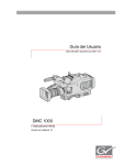
![T] .1](http://vs1.manualzilla.com/store/data/005831826_1-5c5b79be6c7f2f902c022f1ff12b7474-150x150.png)