1
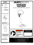
Dual Electronic Basketball System
Owners Manual
Customer Service Center
• N53 W24700 South Corporate Circle • Sussex, WI 53089 • U.S.A.
WARNING!
Tools Supplied:
1 Allen Wrench
1 Phillips Screwdriver
1 Wrench 7/16
1 Wrench5/16
READ AND UNDERSTAND
OPERATOR'S MANUAL
BEFORE USING THIS UNIT.
FAILURE TO FOLLOW
OPERATING INSTRUCTIONS
COULD RESULT IN INJURY
OR DAMAGE TO PROPERTY.
Tools Needed:
4 "D" Cell Batteries
Toll-Free Customer Service Number for U.S: 1-800-558-5234,
For Canada: 1-800-284-8339,
For Europe: 00 800 555 85234 (Sweden: 009 555 85234),
For Australia: 1-800-333 061
Internet Address: http://www.huffysports.com
1
© COPYRIGHT 2000 by HUFFY SPORTS
11/03
P/N 211483E
We appreciate your purchasing one of our many fine products. We are sure that you will be very satisfied with
your selection. Although great care and effort have been taken, occasionally problems may occur. To ensure
prompt and correct handling of any problems, or to answer any questions, please contact our Toll-Free Customer
Service Number listed on front page. Service will be quicker if you have your Model Number
(found on carton) and assembly instructions ready when calling.
IMPORTANT!
Remove all contents from boxes.
P/N 211483E
11/03
2
Get to know the basic parts of your basketball system.....
FRONT
BACKBOARD
RIMS
TARP
SUPPORT
POLES
3
11/03
P/N 211483E
PARTS LIST - (See Hardware Identifier)
Item Qty
P/N
1
2 200745
2
2 200746
3
2 200747
4
1 200748
5
1 200749
6
2 200750
7
2 200752
8
2 200753
9
1 200754
10
2 200755
11
2 200756
12
2 200757
13
1
14
1
15
1 200760
16
2 200761
17
2 200762
18
1 200763
19
2 200764
20
4
21
1 200766
22
2 200767
23
6 200768
24
8 200770
25
8 200771
26
16 200772
27
8 200773
28
6 200774
29
8 200775
30
8 200776
31
32 200777
32
20 200778
33
10 200779
34
1 200780
35
12 201936
36
1 200972
37
1 203358
P/N 211483E
11/03
Description
Net Hanger Tubes
Board Mounting Vertical Support Tube
Vertical Support Tube
Horizontal Cross Tube
Horizontal Cross Brace
90 degree corner Back Leg Support Tube
Floor Mounting Support Tube, Short
Angle Corner, Front Leg Support Tube
Horizontal Front-Ramp Support Tube
Front Ramp Support Tube
Ramp Support Tube, Long
Back Ramp Support Tube
Wood Backboard
Ball Ramp With Side Netting
Electronic Score Keeper
Switch And Paddle Assm
12" Tubular Rims
Red Plastic Display Lens
Nylon Net
7" Rubber Ball
AC Adapter
Metal Back Plate
Plastic Tube Caps
#10 x 1 Phillips Head Bolt
#10 Hex Nut
Black Plastic Net Clips
¼ x 3 ½ Socket Head Screws
¼ x 2 ½ Socket Head Screws
¼ x 3/8 Socket Head Screws
¼ x 1.0 Socket Head Screws
¼" Flat Washer
¼" Flange Nut
Washer, M5
Allen Wrench
Caps Screw
Phillips Screwdriver
Air Pump and Needle
4
1.
Attach rims (17) to backboard (13)
with bolts (30), back plates (22),
and nuts (32) as shown.
Repeat for opposite side.
2.
Attach score keeper (15) to backboard with bolts (24),
washers (33) and nuts (25). Attach lens (18) to front of
score keeper (15) as shown.
25
32
13
15
22
17
30
3.
Attach nets (19) with net clips (26) as
shown. NET SHOULD REST IN SLOT
ON CLIP AS SHOWN FIG. B.
4.
24
18
33
Attach scoring paddles (16) onto backboard
below rims (17) with bolts (24) washers (33) and
nuts (25). Plug wires from paddles into scoring
unit as shown.
DO NOT ENTANGLE WIRES FROM PADDLE IN NET
17
26
24
16
25
33
33
19
FIG B.
33
16
25
24
33
5
11/03
P/N 211483E
5.
Assemble upper framework (1, 2, 23).Secure ball ramp (14) to outer framework as shown Fig. A.
Insert tube (5) through top of ball ramp(14) and attach backboard assembly to tubes 1,2 and 5
with hardware as shown. Repeat for opposite side. Insert horizontal front ramp tube (9) through
bottom of ball ramp (14) as shown.
Fig. A
5
35
1
32
31
1
23
2
2
14
31
28
4
3
28
9
P/N 211483E
11/03
6
6.
Assemble lower framework (6, 7, 8) using bolts (29) and washers (31). Attach to upper framework
as shown. Repeat for opposite side.
3
29
9
31
6
7
8
7.
Assemble side rails (10, 11, 12) using bolt (29) and
washer (31). Install tube caps (23) as shown.
Attach side rails using bolt (27) washer (31),
nut (32) and screw caps (35) as shown.
Repeat for opposite side.
12
29
31
23
27
10
11
35
31
32
23
IMPORTANT!:
Connect side rails
so that bolt heads
face inward.
7
35
32
31
11/03
27
P/N 211483E
8.
Fasten elastic straps in locations shown.
9.
Operation.
BACK VIEW OF SCORING UNIT
DC BATTERY
COMPARTMENT
AC
ADAPTER
ON/OFF
VOLUME
CONTROL
PADDLE CONNECTIONS
1
AC POWER: REMOVE AC ADAPTER FROM BOX. INSERT AC PLUG INTO SLOT ON SCORING UNIT. INSERT AC
ADAPTER INTO 110 VOLT WALL OUTLET. TURN SCORING UNIT “ON”.
DISCONNECT AC POWER WHEN USING DC BATTERY POWER
DC BATTERY POWER: REMOVE BATTERY COVER FROM SCORING UNIT. INSERT 4 “D” CELL BATTERIES INTO
COMPARTMENT. REPLACE BATTERY COVER. TURN SCORING UNIT “ON”.
P/N 211483E
11/03
8
Electronic Game Scoring
1. As a player steps up and sinks a basket, a musical tune will play to signal
the start of a game. After the tune stops and a beep is heard a 00 display
will show.
2. The score keeper will reset the display to 30 seconds and begin counting
baskets.
3. A beep is made for every basket made, a different pitch beep for each
player.
4. Two (2) points per basket made for first 20 seconds of game play.
5. After 20 seconds, a musical tone will play, signaling the start of 3 points per
basket.
6. As time displays 00, a buzzer will sound. The score is retained in memory for
each player.
7. If 30 points or more is scored a "CHARGE" tune will play, earning a 15
second bonus round for each player with each basket made scoring 3 points
8. If 60 points or more is scored, an additional 10 seconds is awarded for each
player. Each basket made scores 3 points
9. As the game is finished a 6 second delay will clear both scores and reset.
10. The highest score made is displayed and retained in memory. The high score
resets to 00 if game is not played after 30 minutes.
11. If an AC power adapter is used, the high score will be retained in memory
unless power is disconnected.
9
11/03
P/N 211483E