1
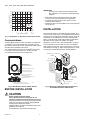
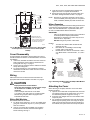
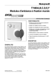
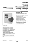
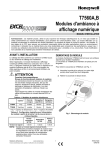
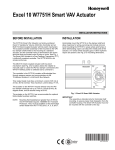
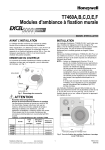
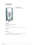
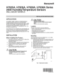
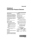
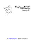
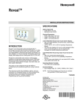
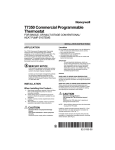
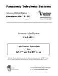
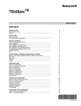
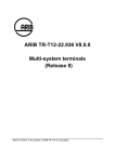
TR21, TR22, TR23, and TR24 Wall
Modules
INSTALLATION INSTRUCTIONS
FEATURES
The TR21, TR22, TR23, and TR24 family of wall modules
include:
• Models with setpoint adjustment.
• Models with humidity output.
• Models with occupied/unoccupied override (bypass)
with LED.
• Models with 3-position (auto/0/1) or 5-position
(auto/0/1/2/3 speed) fan switch.
• LONWORKS® bus jack on all models except the TR21
and TR21-A models.
• Locking cover on all models.
• Operating range 45° to 99° F (7° to 37° C).
• Models (TR22 and TR23) with user-selectable
temperature setpoint dials in Fahrenheit, Celsius, and
Relative (- to +).
PRODUCT DESCRIPTION
SPECIFICATIONS
The TR21, TR22, TR23, and TR24 are a family of direct-wired
wall modules for use with:
— Spyder Unitary Controllers: PUL, PVL
— Excel 10 W7750, W7751a, W7752, and W7753
controllers
— Honeywell Excel 800, 600, 500, 100, and 80 (all fully
programmable) controllers
— W7761 Controller
— ComfortPoint LON Controllers: CP-UL, CP-VL
Models: For specific model information, see TR21, TR22,
TR23, and TR24 Wall Modules – Specification Data,
form 63-1321.
All models have a space temperature sensor. Some models
have a temperature dial, setpoint adjustment, LONWORKS bus
jack, override (bypass) with LED, and fan switch.
NOTE: Refer to the TR21, TR22, TR23, and TR24 Wall
Modules – Specification Data, form 63-1321, for
specific model features and additional information.
a The
TR21, TR22, TR23, and TR24 wall modules are not
compatible with W7751A,C,E,G Controllers.
Environmental Ratings:
• Operating Temperature: 45° to 99° F (7° to 37° C).
• Shipping Temperature: -40° to 150° F (-40° to 65.5° C).
Accessories: 50007298-001 (pack of 12) medium, cover
plate; 6-7/8 x 5 in. (175 x 127 mm).
Approvals: CE; UL94 plastic enclosure; FCC Part 15, Class B
Temperature Sensor
TR21, TR22, TR23, and TR24 20K Ohm Nonlinearized
Sensor:
All models are furnished with a 20K Ohm nonlinear NTC
temperature sensor that follows a specific temperature
resistance curve. See Fig. 1 on page 2.
NOTE: The TR21-A wall module model has two (2) 20K
Ohm nonlinear NTC temperature sensors in parallel,
which provide 10K NTC temperature sensing
necessary for averaging.
62-0267-09
TR21, TR22, TR23, AND TR24 WALL MODULES
IMPORTANT
All wiring must comply with local electrical codes
and ordinances or as specified on installation wiring
diagrams.
80K
RESISTANCE (OHMS)
70K
60K
— Wall module wiring can be sized from 16 to 22 AWG
(1.31 to 0.33 sq. mm) depending on the application.
— The maximum length of wire from a device to a wall
module is 1000 ft. (305 m).
— Twisted pair wire is recommended for wire runs longer than
100 ft. (30.5 m).
50K
40K
30K
20K OHM AT
77oF (25oC)
20K
10K
INSTALLATION
30
0
40
50
10
60
70
20
80
90
100
30
TEMPERATURE (DEGREES)
110 oF
oC
40
M5874A
Fig. 1. Temperature vs. Resistance for Nonlinear Sensor.
Communications
All wall modules (except the TR21 and TR21-A models) have
a LONMARK® bus communications port. If needed, the jack
plug must be removed in the field, and terminals 3 and 4 wired
according to the installation instructions.
The recommended wire size for the LONMARK® bus is Level
IV, 22 AWG (0.34 sq.mm) plenum or non-plenum rated,
non-shielded, twisted pair, solid conductor wire.
Mount the wall module on an inside wall approximately 54 in.
(1372 mm) from the floor (or in the specified location) to allow
exposure to the average zone temperature. Do not mount the
wall module on an outside wall, on a wall containing water
pipes, or near air ducts. Avoid locations that are exposed to
discharge air from registers or radiation from lights,
appliances, or the sun. See “Cover Disassembly” on page 3.
The wall module can be mounted on a wall, on a standard
utility conduit box using No. 6 (3.5 mm) screws or on a 60 mm
wall outlet box (see Fig. 3). When mounting directly on a wall,
use the type of screws appropriate for the wall material.
STANDARD UTILITY CONDUIT BOX
SUBBASE
NO. 6 SCREW
FRONT COVER
TEMPERATURE DIAL,
FAHRENHEIT DIAL SHOWN
(TR22 AND TR23 MODELS ONLY)
80
60
70
LED (TR23 AND TR24 MODELS ONLY)
BYPASS (OVERRIDE) BUTTON
(TR23 AND TR24 MODELS ONLY)
FAN SWITCH, 3 OR 5 POSITION
DEPENDING ON MODEL
(TR22, TR23, AND TR24 MODELS ONLY)
60 mm WALL
OUTLET BOX
LOCKING TAB SLOT (X2)
SUBBASE
LON CONNECTOR,
SHOWN WITH PROTECTIVE CAP IN PLACE
(NOT AVAILABLE ON TR21 AND TR21-A MODELS)
3.5 mm SCREW
M28125
FRONT COVER
Fig. 3. Mounting on Standard Utility Conduit Box or
60 mm Wall Outlet Box (TR23 Shown).
Fig. 2. Wall Module Features (TR23-F Shown).
BEFORE INSTALLATION
CAUTION
Erratic System Operation Hazard.
Failure to follow proper wiring practices can
introduce disruptive electrical interference (noise).
Keep wiring at least one foot away from large inductive
loads such as motors, line starters, lighting ballasts,
and large power distribution panels.
Shielded cable is required in installations where these
guidelines cannot be met.
Ground shild only to grounded controller case.
62-0267—09
M28126
2
TR21, TR22, TR23, AND TR24 WALL MODULES
3.
3 (76)
4.
1 1/2 (38)
9/16 (14)
1 3/16 (31)
7/8 (22)
4 13/16 (122)
70
NOTE: Wire the Lon connection (terminals 3 and 4) using
Level IV 22 AWG (0.34 mm2) plenum or non-plenum
rated, unshielded, twisted pair, solid conductor wire.
STANDARD
UTILITY
CONDUIT
BOX (2 X 4)
MOUNTING
HOLES
Wiring Examples
Table 1 on page 4 illustrates DIP switch settings and terminal
connections for the wall modules. Refer to the TR21, TR22,
TR23, and TR24 Wall Modules – Specification Data, form
63-1321, for additional DIP Switch information.
80
60
2 3/8 (60)
IMPORTANT
SW 2 on DIP Switch S2 is used for factory calibration
of the temperature setpoint potentiometer.
Depending on calibration, this switch may be set in
either the On or Off position.
DO NOT change the position of this switch.
2 1/4 (57)
3/16 (5)
70
65
75
15
°C +
85
–
80
60
20
25
INSIDE OF
FRONT
COVER
°F
Insert the wire in the required terminal location and
tighten the screw to complete the termination.
Review and verify the terminal connection wiring and
DIP switch settings illustrated in Table 1 on page 4.
TEMPERATURE LIMIT
SCREW POSITION (X12)
NOTE: IF DESIRED, INSERT THE
TWO SETPOINT SCREWS INTO
THE DESIRED POSITIONS.
NOTES:
1.
55
M25482
Fig. 4. Wall Module Subbase Dimensions in Inches (mm)
and Temperature Limit Set Screw Locations (TR23
Shown).
2.
3.
Cover Disassembly
A snap-fit locking mechanism is used to attach the cover of
the wall module to its subbase. To disassemble the cover from
the subbase:
1. Insert a thin, flat blade screwdriver into each of the two
slots at the bottom of the module to release the two
locking tabs. See Fig. 2 on page 2.
2. Tilt the cover out and away from the subbase to release
the top two locking tabs.
3. To change the dial (e.g. from Fahrenheit to Celsius)
release the two tabs on the inside of the front cover and
remove the old dial.
1/2
(13)
The TR21 and TR22 models do not use DIP
Switch S1 and S3.
DIP Switch S1 is used only on the humidity
models, TR21-H and TR23-H.
Models TR21 and TR21-A use terminals 1 and 2
only. Model TR21-J uses terminals 1, 2, 3, and 4
only.
1. STRIP 1/2 IN.
2. TWIST WIRES
TOGETHER
WITH PLIERS
(A MINIMUM OF
THREE TURNS).
Wiring
Attach the wires from the device sensor terminals to the
appropriate wall module terminals. See Table 1 on page 4.
CONTROLLER OR
WALL MODULE
E-BUS CONNECTOR
TERMINALS
(13 MM) FROM
WIRES TO BE
ATTACHED AT
ONE TERMINAL.
3. CUT TWISTED END OF WIRES TO
3/16 IN. (5 MM) BEFORE INSERTING
INTO TERMINAL AND TIGHTENING
SCREW. THEN PULL ON EACH WIRE
IN ALL TERMINALS TO CHECK FOR
GOOD MECHANICAL CONNECTION.
M11413
Fig. 5. Attaching Two Wires (20 to 22 AWG) to Wall Module
Terminals.
CAUTION
Improper Electrical Contact Hazard.
Screw type terminal blocks are designed to accept
no more than one 16 AWG (1.31 sq. mm)
conductor.
Connect multiple wires that are 16-18 AWG
(1.31-0.82 sq. mm) with a wire nut. Include a pigtail
with this wire group and attach the pigtail to the
individual terminal block.
Wiring Wall Modules
Wire the terminal block as follows:
1. For single wires, strip 3/16 in. (5 mm); for multiple wires
going into one terminal, strip 1/2 in. (13 mm) insulation
from the conductor.
2. If two or more wires (20 to 22 AWG only) are being
inserted into one terminal, twist the wires together
before inserting. See Fig. 5.
3
Attaching the Cover
When all wiring is complete, attach the cover of the Wall
Module as follows:
1. Optional: For models with a temperature dial, insert the
two setpoint screws into the inside of the cover to set
the desired temperature range limit. See Fig. 4.
2. Press the cover straight down onto the subbase until it
snaps into place.
3. For models with a temperature dial, insert the desired
dial through the opening in the cover. Align the keyed
shaft on the knob with the keyed slot into the fitting on
the subbase, then press down until it snaps into place.
62-0267—10
TR21, TR22, TR23, AND TR24 WALL MODULES
Wiring and DIP switch settings:
See Table 1 to determine DIP switch positions and terminal usage for each controller.
Table 1. DIP Switch Settings and Terminal Connections.
Controller Model(s)
No fan switching from sensor
DIP SWITCH
S1
1
ON
2
3
4
5
OVERRIDE
1
LED
M28128
SETPT
1 DIP SWITCH S1 FOR HUMIDITY MODELS ONLY.
LON -
SW1 SW2 SW3
LON +
T7350: Use +/- offset knob
only!
DIP SWITCH S3
(TR23 AND TR24 ONLY.)
GND
ON
NOT USED ON TR22
DO NOT CHANGE THIS
SWITCH POSITION.
SW1 SW2
Spyder: PUL, PVL
NOT USED ON TR24
DIP SWITCH S2
ON
SW1 SW2
TR22-TR24 Terminal Connections
SENSOR
XL1O:
W7750, W7751, and W7752
TR23-TR24 DIP Switch Settings
6
7
8
9 10 11 12
M28133
NOTE: These switch positions are the factory
default settings for non-fan models.
Fan switching from sensor.
DIP SWITCH ON
S1
1
4
5
FAN
3
1 DIP SWITCH S1 FOR HUMIDITY MODELS ONLY.
DIP SWITCH
S1
1
ON
ON
DIP SWITCH S2
8
4
5
6
7
OVERRIDE
FAN
3
LED
2
BYPASS RET
1
M31110
9 10 11 12
ON
SW1 SW2
0 TO 5 VDC
4 TO 20 mA
ON
ON
8
9 10 11 12
SW1 SW2
1
SW1 SW2
M28132
4
HUM
0 TO 10 VDC
2
3
4
5
6
7
REFER TO CONTROLLER SPECIFIC
WIRING ABOVE FOR TERMINAL
CONNECTIONS 1 THROUGH 10.
M31111
24 VAC
8
DIP SWITCH S1
62-0267—09
M31112
SW1 SW2 SW3
1 DIP SWITCH S1 FOR HUMIDITY MODELS ONLY.
For humidity models – TR21-H
and TR23-H only!
9 10 11 12
NOT USED ON TR22
LON -
LON +
DIP SWITCH S3
(TR23 and TR24 ONLY.)
GND
• Used with TR23, TR24,
TR22-F5, TR23-F3, and
TR23-F5 models.
7
NOT USED
ON TR24
DO NOT CHANGE THIS
SWITCH POSITION.
SW1 SW2
ON
6
SETPT
SW1 SW2
M28129
SENSOR
Excel 600/500/100/80/50
Any controller noted above.
OVERRIDE
SETPT
2
LED
LON -
1
SW1 SW2 SW3
Spyder: PUL, PVL
XL5000:
LON +
DIP SWITCH S3
(TR23 and TR24 ONLY.)
GND
SW1 SW2
ON
W7753
DO NOT CHANGE THIS
SWITCH POSITION.
SENSOR
SW1 SW2
NOT USED ON TR24
NOT USED ON TR22
DIP SWITCH S2
ON
M28137
TR21, TR22, TR23, AND TR24 WALL MODULES
TR22 and TR23 Setpoint Adjustment
Humidity Settings (DIP switch S1)
For the TR22 and TR23 Wall Modules with a setpoint
adjustment, the controller must be programmed for the values
in Table 2 and Table 3.
The humidity sensing control mode is set with this 2-position
DIP switch. Refer to Fig. 4 on page 3 for location of DIP switch
S1.
Table 2. Setpoint Values.
NOTE: These switch settings apply only to the TR21-H and
TR23-H models.
Setpoint Value
Program Setting
55°F (13°C)
2.773 V
65°F (18°C)
2.148 V
75°F (24°C)
1.345 V
85°F (29°C)
0.43 V
To change the setting, first disconnect the power, then set
SW1 and SW2 according to Table 5.
Table 5. DIP Switch S1 Settings.
Table 3. Wall Module Setpoint Configuration.
Setpoint
Resistance (Ohms)
°F Absolute
55°F
9574
85°F
1426
Relative
°C Absolute
-9°F offset from 70°F
9574
+9°F offset from 70°F
1426
12°C
9945
30°C
1150
TR21-H
TR23-H
Description
Fahrenheit scale knob (pack of 20)
KNOB-O
Relative scale knob (pack of 20)
OFF
ON
ON
OFF
70
80
60
KNOB-F
0-5 Vdc
4-20 mA
The Excel 10 controllers (W7750, W7751, W7752, and
W7753) provide timed occupied and unoccupied temperature
setpoints for the Wall Module, see Fig. 6. The override
pushbutton is used to change the controller into the modes
shown in Table 6 and illustrated in Fig. 7 on page 6. The
override (bypass) LED displays the override status of the
controller.
Table 4. Knob Model Numbers
Celsius scale knob (pack of 20)
OFF
When Used With Excel 10 Controllers:
The TR23-KL and TR23-H-KL ship in packs of 20 and are
supplied without setpoint adjustment knobs. Knobs can be
ordered separately. See Table 4 for Knob model numbers.
Model
2
OFF
TR23 and TR24 Wall Module Override
(Bypass) Pushbutton and LED
Operation
TR23-KL and TR23-H-KL
KNOB-C
1
0-10 Vdc
Wall Module Model
Model
Individual
Switches
Sensing
Control
LED
1
OVERRIDE (BYPASS)
PUSHBUTTON
1
LED AND OVERRIDE (BYPASS) PUSHBUTTON AVAILABLE
ONLY ON THE TR23 AND TR24 MODELS.
M28144
Fig. 6. LED and override pushbutton locations
(TR23-F Wall Module shown).
5
62-0267—09
TR21, TR22, TR23, AND TR24 WALL MODULES
TR22-F5, TR23-F3, and TR23-F5 Wall
Module Fan Switch
Table 6. Wall Module Operation.
Pushbutton Held Down
Controller Model
With the switch in the far left position (Auto), the fan
automatically runs at the speed determined by the controller
temperature control algorithm.
LED Status
0 to 1 second
No override
Off
1 to 4 seconds
Timed occupied
override
On
4 to 7 seconds
Unoccupied override Single blink per second
Longer than 7 seconds
No override
not applicable
Continuous occupied Two blinks per second
overridea
a
With the switch in the 0 position, the fan is off. Position 1 is fan
speed 1, etc.
The wall module fan speed switch overrides the temperature
control algorithm.
Off
When Used With Excel 10 Controllers:
The Excel 10 Controllers (W7750, W7751, W7752, and
W7753) can be programmed so that the fan speed switch and
override button function the way that the application engineer/
programmer wants. See Table 7 for controller-programming
resistances. Switch 1 on Dip Switch S2 adds 10k Ohms
resistance when OPEN (for Excel 600-80 controllers) and
removes it when CLOSED (for Excel 10 controllers).
Remote function, which is generated from the network.
RESET
NOT ASSIGNED
(LED OFF)
PRESS FOR
LESS THAN
ONE SECOND
PRESS FOR ONE
TO FOUR SECONDS
Table 7. Program Settings for Wall Modules with
Fan Switch using Excel 10 Controllers.
BYPASS
TIMEOUT
OVERRIDE
OCCUPIED
(LED ON)
For Switch Position
Auto
PRESS FOR FOUR
TO SEVEN SECONDS
PRESS FOR
LESS THAN
ONE SECOND
UNOCCUPIED
(LED BLINK)
Comment
Left most position
0
2686 ±127
Fan Off position
1
3866 ±139
2
3041 ±130
3
4601 ±146
Right most position
Override button closed Closed circuit
PRESS FOR
MORE THAN
SEVEN SECONDS
M28145
Fig. 7. Override pushbutton operation.
When Used With Excel 600/500/100/80/50
Controllers:
The application engineer/programmer can program the
override (bypass) and LED to operate in any manner desired.
The override (bypass) input is a dry contact, normally open,
momentary digital input when the wall module does not have a
fan switch. When a fan speed switch (basically a series of
resistances based on fan switch position) is present, the
override button is an analog input. See Table 4 for
resistances.
When Used With T7350 Thermostat:
TR21, TR21-A, TR21-H, TR22, TR23, and TR24 are the
models compatible with the T7350 thermostat. When using
with the T7350 thermostat be sure to use the relative +/- offset
knob only. The Celsius and Fahrenheit knobs will not work
properly with the T7350 Thermostat.
62-0267—09
Resistance (Ohms)
1861 ±119
6
When Used With Excel 600/500/100/80/50
Controllers:
Excel 600/500/100/80 Controllers can be programmed so that
the fan speed switch and override button function the way that
the application engineer/programmer wants. See Table 8 for
controller-programming resistances. Switch 1 on Dip Switch
S2 adds 10k Ohms resistance when OPEN (for Excel 600-80
controllers) and removes it when CLOSED (for Excel 10
controllers).
Table 8. Program Settings for Wall Modules with
Fan Switch using Excel 600/500/100/80 Controllers.
For Switch Position
Resistance (Ohms)
Comment
Auto
11.861K ±119
Left most position
0
12.686K ±127
Fan Off position
1
13.866K ±139
2
13.04K ±130
3
14.60K ±146
Override button closed 10K ±100
Right most position
TR21, TR22, TR23, AND TR24 WALL MODULES
7
62-0267—09
TR21, TR22, TR23, AND TR24 WALL MODULES
By using this Honeywell literature, you agree that Honeywell will have no liability for any damages arising out of your use or
modification to, the literature. You will defend and indemnify Honeywell, its affiliates and subsidiaries, from and against any
liability, cost, or damages, including attorneys’ fees, arising out of, or resulting from, any modification to the literature by you.
LONWORKS® is a registered trademark of Echelon® Corporation.
LONMARK® and the LonMark Logo are trademarks of the LonMark Association.
Automation and Control Solutions
Honeywell International Inc.
Honeywell Limited-Honeywell Limitée
1985 Douglas Drive North
35 Dynamic Drive
Golden Valley, MN 55422
Toronto, Ontario M1V 4Z9
customer.honeywell.com
® U.S. Registered Trademark
© 2009 Honeywell International Inc.
62-0267—09 E.K. Rev. 09-09