1
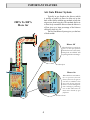
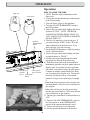
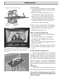
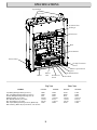
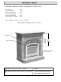
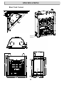
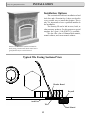
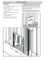
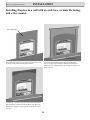
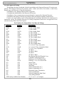
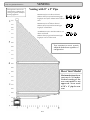
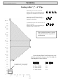
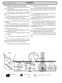
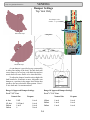
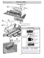
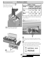
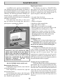
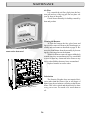
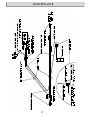
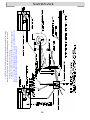
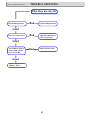
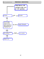
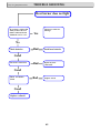
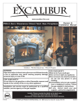
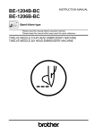
Installation & Operating Manual The Harman Built Serenity III HB 38 DV “Ce manuel est disponible en Français sur demande” R8 SAFETY NOTICE PLEASE READ THIS ENTIRE MANUAL BEFORE YOU INSTALL AND USE YOUR NEW ROOM HEATER. FAILURE TO FOLLOW INSTRUCTIONS MAY RESULT IN PROPERTY DAMAGE, BODILY INJURY, OR EVEN DEATH. FOR USE IN THE U.S. AND CANADA. SUITABLE FOR INSTALLATION IN MOBILE HOMES IF THIS HARMAN STOVE IS NOT PROPERLY INSTALLED, A HOUSE FIRE MAY RESULT. FOR YOUR SAFETY, FOLLOW INSTALLATION DIRECTIONS. CONTACT LOCAL BUILDING OR FIRE OFFICIALS ABOUT RESTRICTIONS AND INSTALLATION INSPECTION REQUIREMENTS IN YOUR AREA. CONTACT YOUR LOCAL AUTHORITY (SUCH AS MUNICIPAL BUILDING DEPARTMENT, FIRE DEPARTMENT, FIRE PREVENTION BUREAU, ETC.) TO DETERMINE THE NEED FOR A PERMIT. CETTE GUIDE D'UTILISATION EST DISPONIBLE EN FRANCAIS. CHEZ VOTRE CONCESSIONNAIRE DE HARMAN STOVE COMPANY. SAVE THESE INSTRUCTIONS. R1 7R WARNING: If the information in this manual is not followed exactly, a fire or explosion may result causing property damage, personal injury or loss of life. A. FOR YOUR SAFETY Do not store or use gasoline or other flammable vapors and liquids in the vicinity of this or any other appliance. B. FOR YOUR SAFETY: WHAT TO DO IF YOU SMELL GAS • Do not try to light any appliance. • Open windows. • Extinguish any open flame. • Do not touch any electrical switch; do not use any phone in your building. • Immediately call your gas supplier from a neighbor's phone. Follow the gas supplier's instructions. • If you cannot reach your gas supplier, call the fire department. C. Installation and serv ice must be performed by a qu alified gas installer, service agency, or the gas supplier. 2 Table of Contents Introduction 4 Safety Precautions 4 Operation 6 Specifications 8 Installation Arch Face Victorian Face 12 15 16 Venting Damper Settings 20 24 Changing to LP 25 Log Placement 27 Option Installation Thermostat Remote Control Remote Register Kit 28 28 29 Maintainence Wiring Diagram 35 37 Trouble Shooting 41 Warranty 46 Manufactured by The Harman Stove Company 352 Mountain House Rd. Halifax PA 17032 M :PM 65-FILES\M ANUALS\HBF\hb38dvR6.p65 Introduction sageways of the Serenity III be kept clean. When operating your Harman Serenity III Gas Fireplace, respect basic safety standards. Read these instructions carefully before you attempt to operate the fireplace. Failure to do so may result in damage to property or personal injury and may void the product warranty. Consult with your local building code agency and insurance representative before you begin your installation to ensure compliance with local codes, including the need for permits and follow-up inspections. Several issues must be addressed when selecting a suitable location for your Serenity III Gas Fireplace. Observing required clearances to combustible materials, the proximity to a safe chimney or venting system location, and the accessibility of the gas and electrical supply must all be considered. In addition, selecting a location that takes advantage of the building's natural air flow is also desirable to maximize the heating effectiveness of the fireplace. In many cases, this is a central location within the building. The Harman Serenity III Direct Vent Gas Fireplace is a listed gas-fired direct vent room fireplace tested by Intertek Testing Services/Warnock Hersey to ANSI Z21.88-2002/ CSA2.33-M02. CAN-CGA-2.17M91. The installation of the Serenity III Direct Vent Gas Fireplace must conform with local codes, or in the absence of local codes, with National Fuel Gas Code, ANSI Z223.1 — latest edition and CAN 1 B1-149.1 and .2 Installation Code. Also for use in mobile (manufactured) homes after home is sited. Mobile (manufactured) home installations must adhere to current editions of Title 24 CFR, part 3280, or CSA Z240.4. CAUTION: This appliance must be vented to the outside. Installation and repair of the Serenity III Direct Vent Gas Fireplace should be done by a qualified service person. The appliance should be inspected before use and at least annually by a qualified service person. More frequent cleaning may be required due to excessive lint from carpeting, bedding material, etc. It is imperative that control compartments, burners, and circulating air pas- Any safety screen or guard removed for servicing an appliance must be replaced prior to operating the appliance. Due to high temperatures, the Serenity III Direct Vent Gas Fireplace should be located out of traffic and away from furniture and draperies. This appliance may be installed in an aftermarket permanently located (mobile) home, where not prohibited by local codes. This appliance is only for use with the type(s) of gas indicated on the rating plate. This appliance is not convertible for use with other gases, unless a certified kit is used. Children and adults should be alerted to the hazards of high surface temperatures and should stay away to avoid burns or clothing ignition. Young children should be carefully supervised when they are in the same room as the appliance. Cet appareil peut etre installe dans un maison prefabriquee (mobile) deja installee a demeure si les reglements locaux le permettent. Cet appareil doit etre utilise uniquement avec les types de gas indiques sur la plaque signaletique. Ne pas l utiliser avec d autres gas sauf si un kitde conversion dertifie est installe. Clothing or other flammable materials should not be placed on or near the appliance. Surveiller les enfants. Garder les vetements, les meubles, lessence ou autres liquides a vapeur inflammables lin de lappareil. 4 IMPORTANT FEATURE Air Gate Blower System Typically in gas fireplaces the blower (which is usually an option) is placed to blow air up the back of the firebox without any method to keep the air pressure from being lost. This method allows air to flow freely around the blower when the blower is off but gives up a large percentage of the blowers efficiency when it is on. The Air Gate Blower System gives you the best of both worlds. 200% To 300% More Air Blower Off When the blower is off the air gate is in the open position which allows air to flow freely through the air chamber and up through the heat exchanger. Air Gate Open Blower On When the blower is turned on, the air pressure from the blower forces the air gate to seal the air chamber. This forces all the air from the blower to travel through the heat exchanger producing two to three times more air than other b rands of gas fireplaces. Air Gate Closed 5 OPERATION Operation High-Low Gas Control ON-OFF/ THERMOSTAT Switch Three Speed Rear Burner Blower Switch ON/OFF Switch Piezo Ignitor Button PILOT 6 HOW TO LIGHT THE FIRE 1. STOP! Read the safety information on the front cover. 2. If using the optional thermostat, set thermostat to the lowest setting. 3. Turn off electric power to the appliance. 4. Turn the ON-OFF/THERMOSTAT switch to the OFF position. 5. Push in the gas control knob slightly and turn it clockwise to "OFF." NOTE: THE KNOB CANNOT BE TURNED FROM "PILOT" TO "OFF" UNLESS IT IS PUSHED IN SLIGHTLY. DO NOT FORCE IT. 6. Wait five (5) minutes to clear out any gas. If you then smell gas, STOP! Follow "B" in the safety information on the front cover. If you don't smell gas, go to the next step. 7. Set the High-Low Regulator to High by turning it fully counterclockwise. 8. Press in the gas control knob slightly and turn counterclockwise to "PILOT." 9. Find the pilot by looking through the round opening on the left end of the center log. 10. Push the control knob fully down and hold. Immediately push the red piezo ignitor button to light the pilot. It is normal to have to push the red button several times before the pilot ignites. Continue to hold the control knob in for about one (1) minute after the pilot is lit. Release the knob and it will pop back up. Pilot should remain lit. If it goes out, repeat steps 5 through 9. •If the knob does not pop up when released, stop and immediately call your service technician or gas supplier. •If the pilot will not stay lit after several tries, turn the gas control knob to "OFF" and call your service technician or gas supplier. 11. Turn the gas control knob counterclockwise to "ON." 12. Place the ON-OFF/THERMOSTAT switch in the ON position or in the THERMOSTAT position if the optional thermostat is used. 13. Turn on the electric power to the heater. 14. Set the optional thermostat to the desired OPERATION room temperature. 15. Set the High-Low Regulator to desired setting: Turn fully counterclockwise for High and fully clockwise for Low. 16. Press the rear burner switch to the “ON” or “OFF” position as desired. This switch will return to the center position after it is pressed. This is normal as well as a faint click when pressed. The main burner must be lit before the rear burner will light. The rear burner may be turned “ON” or “OFF” at any time. Bottom rear view of burner module. Rear Burner Adjuster Front Burner Adjuster NOTE: An odor, resulting from the initial heating of new materials in your heater, is not unusual during the first fire, and in most cases will disappear after an hour or two. HOW TO TURN OFF THE FIRE 1. If using optional thermostat, set thermostat to the lowest position. 2. Turn off the electric power to the appliance. 3. Turn the ON-OFF/THERMOSTAT switch to the OFF position. 4. Push in the gas control knob slightly and turn it clockwise to “OFF.” NOTE: The knob cannot be turned from “PILOT” to “OFF” unless it is pushed in slightly. Do not force it. Normal Flame pattern. Note: Flames will vary in height and position depending on the placement and the amount of ember wool. FLAME HEIGHT ADJUSTMENT There are separate adjusters for the front and rear burners. These adjusters can be accessed by reaching to the left side of the control panel and to the back of the unit. Turn the adjusters counterclockwise (up) to increase flame height and clockwise (down) to decrease. See above left. Adjusting the flames too high will cause them to have black tips and cause sooting. Sooting can cause the glass to get dirty. Pilot Flames If pilot flames are less than shown at left, use pilot adjuster shown on page 36, to increase flames, Warning: The unit and adjuster may be hot. Wear gloves and arm protection if making adjustments while in operation 7 SPECIFICATIONS Top Standoffs Vent Collar Accordion Heat Exchanger Glass Door Brick Burner Module Electrical Box On-Off- Thermostat Switch Blower Speed Switch Ignitor Blower Battery Pack On-Off-Pilot Knob Rear Burner Switch Top Vent RATINGS Input Rating (Btu/hr)(0-4500 ft.)(0-1375 m) Min. Input Rating (Btu/hr)(0-4500 ft.)(0-1375 m) Orifices (DMS)(front/rear)(0-4500 ft.)(0-1375 m) Manifold Pressure (in w.c./kPa) Min. Manifold Pressure (in w.c./kPa) Min. Inlet Pressure (in w.c./kPa) Max. Output (Btu/hr)(0-4500 ft.)(0-1375 m) (Blower Off) Max. Efficiency (Blower On) top vent 84.5%, rear vent 75% NATURAL 43500 23300 31/51 3.5/0.87 1.7/0.42 5.0/1.25 31500 8 PROPANE 43500 23800 52/59 10.0/2.49 6.3/1.6 11.0/2.74 32000 Hi-Low Knob Rear Vent NATURAL PROPANE 41500 22800 32/51 3.5/.087 1.7/0.42 5.0/1.25 31000 41400 23400 52/60 10.0/2.49 6.3/1.55 11.0/2.74 31000 SPECIFICATIONS MINIMUM CLEARANCES FROM COMBUSTIBLE CONSTRUCTION Unit to floor Face to side wall Unit to top stand-offs Unit to side stand-offs Unit to rear stand-offs Top of Glass to 7” Mantel 0 in. 7 in. 0 in. 0 in. 0 in. 26in. Electrical Rating: 120 Volts, 60 Hs, >2.75 AMP This fireplace may be placed on a wood floor. Must be Noncombustible 2 Optional Arch Hood 1 Hearth is not required in front of the fireplace 1. Clearance from top of glass to 7” mantel. 26 inches 2. Clearance from top of ach to bottom of wood facing. 10 inches with optional arch hood and 15 inches without arch hood 9 SPECIFICATIONS Rear Vent Corner 11” 70” Elictrical Hook-up Gas In 10 SPECIFICATIONS Top Vent Corner 64” Elictrical Hook-up Gas In 11 Only For Qualified Installers INSTALLATION Installation Options This section deals with basic installation of and Arch face and a Victorian face. It does not describe every possible way to install this fireplace. This is why it is important to have a qualified installer do the installation. The Serenity III can be laid in stone, brick, or other masonry products. For this purpose a special template face ( part # 1-00-4238231 ) is available. We also offer a line of Harman Built mantels, mantel cabinets, and corner mantel cabinets. Shown is the M2 Mantel Cabinet with marble finish facing, raised marble finish hearth and a gold plated Arch face with Arch hood. Typical Tile Facing Sectional View Wonder Board Drywall Arch Face Tile Wood Mantel 12 Only For Qualified Installers INSTALLATION Placement This appliance must be electrically connected and Here are some of the things that will effect the grounded in accordance with local codes or , in the absense of local codes, with the current edition of exact placement of the fireplace. NFPA 70-National Electric Code or CSA C22.11. Top or rear flue Canadian Electrical Code. 2. Arch face or mantle face. Arch face - Must decide on mantel and front This unit shall not be installed on carpet, vinyl facing material. tile, or combustible material other than wood 3. Raised hearth, flat hearth or raised with no hearth. 4. One, two or no remote duct kits. 5. Thermostat position. 6. Gas line hook-up is on the right side. 7. Electrical hook-up is on the left side. 13 Only For Qualified Installers INSTALLATION Installing fireplace in a wall with an arch face, ceramic tile facing, and a face mantel. Noncombustible 1 inch thick Noncombustible material such as Dura-rock must be used as facing on the front of the fireplace cabinet. A one inch space under the front edge of the fireplace allows room for hearth material. Hearth material that is thicker must be compensated for by raising the fireplace the proper amount. Ceramic tile, marble or other decorative noncombustible material may be used in front of the Dura-rock. The total thicknes for all layers of facing material may not exceed one inch. 14 Only For Qualified Installers INSTALLATION Installing The Arch Face To install the arch face, place the hooks on the bottom rear of the face into the hook slots on the fireplace. Next with the top latches handles in the horizontal position push the face against the fireplace and swing the latches straight down causing them to enter the top face slots. Latch Handles Removing The Arch Face To remove the face, unlatch the top latches, tilt the top of the face away from the fireplace and lift the face out of the bottom slots. Face Hooks Slots for face latches Slots for face hooks 15 Only For Qualified Installers INSTALLATION Assembling the Victorian Face 1. Position the mantel face down on the floor. 2. Place the left piller over the two studs on the left side of the mantel. Install two washers and nuts and tighten. 3. Place the left side of the breast plate into the slots on the left pillar. 4. Place the Left hinge pin of the top grill door into the round hole in the pillar. 5. Place the left hinge pin of the bottom grill door into the round hole in the bottom of the pillar. 6. Place the right pillar over the studs on the right side of the mantel face while simultaneously placing right ends of the doors and breast plate into their slots on the right pillar. Some assistance is helpful. 7. Install any decorative panels at this time. 16 INSTALLATION Only For Qualified Installers Installing Fireplace To use Victorian Face Drywall Bracket Nails When installing the fireplace to use the Victorian Face the unit must be positioned back 1/2 inch farther than with an arch face. A special drywall bracket must be used to allow the drywall to extend down far enough so the face will cover the drywall. 1. Install drywall bracket on top of the stand-offs with two screws. 2. Place the fireplace into the framed opening so the two ends of the drywall bracket rest against the framing. This will position the face of the fireplace 1/2 inch back from the face of the framing. 3. Nail or screw the drywall bracket fast to the framing. 4. Install and finish drywall as desired. Drywall shall not extend below the drywall bracket on the top and not closer to the fireplace cabinet than the vertical wood framing on the sides. Nails Drywall Drywall Bracket Victorion Face Standoff Drywall in Place 17 Only For Qualified Installers INSTALLATION Mounting The Victorian Face 1. Place fiberglass rope in sealing angle with angle mounting bolts loose. 2. Place the face on the fireplace starting at the bottom. 3. Slide the face into place and install the four bolts as shown at left. 4. Slide the sealing angle against the fireplace and tighten the mounting bolts. Note: The face will have a one inch space under it for hearth material. This must be considered when planning the installation. Mounting Holes Complete Face Mounted Sealing Angle 18 Only For Qualified Installers INSTALLATION Burn Only the Fuel for which the Heater is Equipped The Serenity III Direct Vent will burn either natural gas or propane, but requires a change over kit for propane. The label on the burner system module indicates the fuel for which it is equipped. A second label, (on the valve) also indicates the fuel type. Making The Connection The gas inlet is located on the bottom right side of the fireplace. The inlet fitting is a 3/8" female flare flexible pipe. A separate gas shut-off valve and a 1/8" N.P.T. plugged tapping should be installed immediately upstream of the connection to the appliance. The Serenity III Direct Vent Gas Heater must be disconnected from the gas supply piping during any pressure testing of that system at pressures in excess of 1/2 psig (3.5 kPa). The Serenity III gas control valve must be in the OFF position during any pressure testing of the gas supply system at pressures equal to or less than 1/2 psig (3.5 kPa). WARNING: To avoid pipe compounds from entering into the gas train, apply compounds only to male pipe threads and do not apply compound to the first two threads. CAUTION: TEST ALL JOINTS FOR LEAKS BEFORE OPERATING. Gas Pressure Requirements: Correct gas pressure and the use of a properly sized gas supply line are essential for the safe and efficient performance of this appliance. Make sure that the plumber or gas supplier checks the gas supply line and gas pressure at installation. NOTE: Improper gas pressure can affect heater performance, flame color, or cause pilot outage. 19 Natural Gas: Maximum inlet pressure 7.0" w.c. (1.74 kPa) Minimum inlet pressure 5.0" w.c. (1.25 kPa) Gas manifold pressure 3.5" w.c. (0.87 kPa) LPG Gas: Maximum inlet pressure 13" w.c. (3.24 kPa) Minim um inlet p ressure 11" w.c. (2.74 kPa) Gas manifold pressure 10" w.c. (2.49 kPa) DO NOT USE THIS HEATER IF ANY PART HAS BEEN UNDER WATER OR EXPOSED TO MOISTURE CORROSION. IMMEDIATELY CALL A QUALlFlED SERVICE TECHNICIAN TO INSPECT THE HEATER AND REPLACE ANY PART OF THE CONTROL SYSTEM AND ANY GAS CONTROL WHICH HAS BEEN UNDER WATER. RECOMMENDED GAS PIPE DIAMETER Pipe Length Schedule 40 Pipe (Feet) Inside Diameter Tubing, Type L Outside Diameter N.G. L.P. N.G. L.P. 0-10 1/2" 1.3 cm 3/8" 1.0 cm 1/2" 1.3 cm 3/8" 1.0 cm 10-40 1/2" 1.3 cm 1/2" 1.3 cm 5/8" 1.6 cm 1/2" 1.3 cm 40-100 1/2" 1.3 cm 1/2" 1.3 cm 3/4" 1.6 cm 1/2" 1.3 cm 100-150 3/4" 2.0 cm 1/2" 1.3 cm 7/8" 2.3 cm 3/4" 2.0 cm NOTE: NEVER USE PLASTIC PIPE. CHECK TO CONFIRM WHETHER YOUR LOCAL CODES ALLOW COPPER TUBING OR GALVANIZED PIPE. Only For Qualified Installers VENTING Use Only Approved Venting This appliance has been tested and is listed for installation with Simpson Duravent GS venting components. The Simpson Duravent GS warranty will be voided, and serious fire, health, or other safety hazards may result from any of the following actions: • Installation of any damaged Duravent GS component. • Unauthorized modification of the Duravent GS System. • Installation of any component part not manufactured or approved by Simpson Duravent. • Installation other than as instructed by Simpson Duravent and the appliance manufacturer. Consult your local building codes before beginning the installation, and follow the manufacturer's instructions exactly. The Simpson Duravent GS venting components listed below are approved for use with the Serenity Direct Vent Gas Fireplace. Part Numbers for SimpsonDura-Vent Pipe and Fittings 6-5/8 x 4 8” x 5” Description n/a 1208 6” Pipe Length 908B 1208B 6” Pipe Length, Black n/a 1207 9” Pipe Length 907B 1207B 9” Pipe Length, Black 906 1206 12” Pipe Length 906B 1206B 12” Pipe Length, Black 904 1204 24” Pipe Length 904B 1204B 24” Pipe Length, Black 903 1203 36” Pipe Length 903B 1203B 36” Pipe Length, Black 902 1202 48” Pipe Length 902B 1202B 48” Pipe Length, Black n/a 1211 11” to 14-5/8” Pipe, Adjustable 911B 1211B 11” to 14-5/8” Pipe, Adjustable, Black n/a 1217 17” to 24” Pipe, Adjustable 945 1245 45o Elbow 945B 1245B 34o Elbow, Black 990 1290 90o Elbow 990B 1290B 90o Elbow, Black 940 1240 Rnd Support Box/Wall Thimble Cover 941 1241 Cathedral Ceiling Support Box 943 1243 Flashing, 0/12 to 6/12 Roof Pitch 943S 1243S Flashing, 7/12 to 12/12 Roof Pitch 953 1253 Storm Collar 963 1263 Ceiling Firestop 988 1288 Wall Strap 981 1281 Snorkel Termination (36”) 982 1282 Snorkel Termination (14”) 984 1284 Horizontal Square Termination 980 1280 Vertical Termination 991 1291 Vertical Termination, High Wind 950 1250 Vinyl Siding Standoff 1222D (Only available from Harman) 8” x 5” to 6 5/8” x 4” Adaptor 20 Only For Qualified Installers This appliance must not be connected to a chimney flue serving a separate solid fuel burning appliance. VENTING Venting with 8” x 5” Pipe Maximum of four 450 elbows allowed. Subtract three feet of total horizontal pipe length for each of the 3rd and 4th 450 elbows used. Maximum of two 900 elbows allowed. Subtract five feet of total horizontal pipe length for second elbow. A combination of one 900 elbow and two 450 elbows is allowed. Subtract three feet of total horizontal pipe length for each 450 elbow used. Vent termination m ust remain within the shaded area regardless of configuration. Rear Vent Model Maximum horizontal rear v ent run is 24 inches . Vertical venting of the rear vent model is not approved. Never used 6 5/8” x 4” pipe for rear vent. 21 Only For Qualified Installers VENTING Venting with 6 5/8” x 4” Pipe Maximum of four 450 elbows allowed. Subtract three feet of total horizontal pipe length for the 3rd and 4th 450 elbow used. Maximum of two 900 elbows allowed. Subtract five feet of total horizontal pipe length for second elbow. A combination of one 900 elbow and two 450 elbows is allowed. Subtract three feet of total horizontal pipe length for each 450 elbow used. Vent termination m ust remain within the shaded area regardless of configuration. For the Serenity Direct Vent Fireplace, the vent/ air intake termination clearances above the high side of an angled roof are as follows: Roof Pitch Flat to 6/12 7/12 to 9/12 10/12 to 12/124 13/12 to 16/126 17/12 to 21/128 Use Adaptor (Part No. 1222D ) to reduce to 6 5/8 x 4 vent pipe. 22 Feet 1 2 1.2 1.8 2.4 Meters 0.3 0.6 VENTING Only For Qualified Installers Requirements for Terminating the Venting WARNING:Venting terminals must not be recessed into a wall or siding. In addition, the following must be observed: A. The clearance above grade, or a veranda, porch, deck or balcony must be a minimum of 12" (30 cm).1 B. The clearance to a window or door that may be opened must be a minimum of 12" (30 cm).1 C. A 12" (30 cm) clearance to a permanently closed window is recommended to prevent condensation on the window. D. The vertical clearance to a ventilated soffit located above the terminal within a horizontal distance of 2 feet (60 cm) from the center-line of the terminal must be a minimum of 18" (46 cm). E. The clearance to an unventilated soffit must be a minimum of 12" (30 cm). F. The clearance to an outside corner is 11" from center of pipe. G. The clearance to an inside corner is 12" (30 cm). H. A vent must not be installed within 3 feet (90 cm) above a meter/regulator assembly when measured from the horizontal center-line of the regulator.1 I. The clearance to service regulator vent outlet must be a minimum of 6 feet (1.8 m).1 J. The clearance to a non-mechanical air supply inlet to the building or the combustion air inlet to any other appliance must be a minimum of 12 inches (30 cm).1 K. The clearance to a mechanical air supply inlet must be a minimum of 6 feet (1.8 m).1 L. The clearance above a paved sidewalk or a paved driveway located on public property must be a minimum of 7 feet (2.1 m).1,2 M. The clearance under a veranda, porch, deck or balcony must be a minimum of 12 inches (30 cm).1,3 1 As specified in CAN 1 B1-149 Installation Codes (current edition). Note: Local codes or regulations may require different clearances. 2 A vent shall not terminate directly above a sidewalk or paved driveway which is located between two single family dwellings and serves both dwellings. 3 Only permitted if veranda, porch, deck, or balcony is fully open on a minimum of 2 sides beneath the floor. I ns ide Corner Det ail Fixed Closed Openable Fixed Closed Openable V = Vent terminal A = Air supply inlet 23 = Area where terminal is not permitted VENTING Damper Settings Top Vent Only Only For Qualified Installers Vent damper in the number “4” position Maximum Draft Minimum Draft A vent damper is provided on top vent models to allow fine tuning of the draft. Too little draft will cause flames to be too long with black tips and too much draft will cause flames to be short and blue. To adjust the damper, burn the unit on high with both burners for 10 minutes or more. Adjust the vent damper to a position in the ranges listed below that produces the most desirable flame pattern. Note: 1 is less draft and 4 is maximum draft. Range Of Approved Damper Settings For 8” X 5” Vent Natural Gas 6 feet 12 feet 24 feet 36 feet 2 1/2 2 1/2 to 4 1 to 2 1 Range Of Approved Damper Settings For 6 5/8” X 4” Vent Propane 12 feet 24 feet 36 feet 1 to 4 1 to 4 1 to 4 2 to 4 24 Natural Gas Propane 1 to 4 1 to 4 1 to 4 1 to 4 1 to 4 1 to 4 INSTALLATION Only For Qualified Installers Changing to LP 1 Remove screw 3 Remove Orifice Cover 2 Remove Air Deflector 6 4 Remove Screw Remove Rear Burner by sliding to the left. 7 Remove 5 Flame Bridge Lift up on front of burner/grate/ screen assembly and then slide left about 1/2”. The assembly can then be removed. LP Conversion Kit LP Orifice Box Cover LP Pilot Orifice LP Rear Orifice. #60 Rear Flue, #59 Top Flue. LP Front Orifice #52 LP Conversion label LP Valve Conversion Module 8 Remove pilot tower with a 7/16” wrench. Replace Natural Gas orifice with LP orifice. LP Conversion Instructions Top Vent LP Kit Part No. 1-00-08770 Rear Vent LP Kit Part No. 1-00-08771 These kits are only for use in the Serenity series fireplaces. Note: The difference between the top and rear LP kit is the size of the rear orifice (#59 for top and #60 for rear). 25 INSTALLATION Only For Qualified Installers Remove Orifices with a 1/2” wrench or deep well socket. The larger orifice always goes to the front. 9 Vent Orifice Chart Natural Propane Front Rear Front Rear Top 31 51 52 59 Rear 32 51 52 60 Note: The higher the orifice number the smaller hole in the tip. For example, a number 52 oifice has a larger hole than a number 60 orifice. 12 Read instructions packed with LP Change-over Kit. 10 Replace Orifices with the proper size shown in the Orifice Chart. 13 Remove three screws to change knob assembly. Install LP knob assembly in place of the NG assembly. Be sure screws are tight. 14 Place conversion sticker (provided in Kit) on bottom of valve. This is to permanently mark the valve that it has been converted to LP. This label is important in the event that the valve is ever removed and mixed in with other valves. 11 Remove two screws and place Control Panel to the left. Mark the proper box on the control panel with a permanent 15 marker. Note: If no conversion is made, the box for the proper fuel must still be marked. 26 Only For Qualified Installers INSTALLATION Log Placement Rear Log Pins Rear Log Front Log Pin Front Log Side Log Top Log 1 2 Locate two holes in bottom of rear log. Place the rear log down over the two pins to locate the log. Place the front log down over the pin shown above. The front of the log should be parallel with the grate bar. 4 3 Place the side log as shown with the notch in the log behind the angled grate bar. 27 Find the two holes in the bottom of the top log. Place the log down over the pins on top of the front and rear logs. Only For Qualified Installers INSTALLATION (Options) Connecting the Optional Thermostat If the optional thermostat is used, it must be plugged into the terminal strip located in the lower left front corner of the heater. When installing a millivolt control system, use only a special low resistance thermostat. DO NOT USE A REGULAR HEATING THERMOSTAT. Be sure that all electrical connections are clean, free from corrosion, and tight. Inspect connections periodically to confirm that no corrosion has built up over time. When properly installed and maintained, a millivolt control system should give many years of trouble-free service. It is important to use wire of a gauge proper for the length of the wire: Thermostat RECOMMENDED WIRE GAUGES Maximum Length 100' 60' 40' 25' 15' Front Burner Button Wire Gauge 14 16 18 20 22 Remote Control The front button on the remote control can be used to turn the front burner on and off. The rear button is used to turn the rear burner on and off. This remote uses the ultrasonic control method and does not need to be pointed directly at the fireplace. A hand held sending unit, receiving unit, mounting bracket and all wiring are included when you order the remote control. Installation instructions are packed with remote kit. Rear Burner Button 28 Only For Qualified Installers INSTALLATION (Options) Optional Remote Register Kit Register Kit Includes remote register box with blower, speed control, two 8 foot sections of 6” flex pipe, 6” round to 3” x 10” transition, and automatic damper assembly. Flex Pipe 6” Round to 3” x 10” Transition 3” x 10” Duct ( not part of kit ) Automatic Damper Assembly Speed Control Remote Register Box With Blower Floor Register Wall Mounting Brackets Floor Mounting Bracket Wall Register Floor Kit Includes floor register and floor mounting bracket for blower box. Wall Kit Includes wall register and wall mounting brackets for the blower box. 29 Only For Qualified Installers INSTALLATION (Options) Optional Wall Register Kit The Serenity is designed for use with one or two register kits. Each kit can have twenty feet of duct between the fireplace and the register box. The registers can be mounted one floor above or below the fireplace. The register kits are designed to be installed in the house before wall coverings such as drywall are installed. 3”x10” duct is to be used inside walls that are too narrow for the six inch flex duct. Never use a wall cavity as a duct. Doing so can dry out the wood and lower the kindling temperature as well as cause warping. Installing Damper Assembly 1. Remove the top cover on the side that you are installing the damper assembly. 2. Cut the yellow insulation around the edge of the opening. Discard the cutout. 3. Remove bottom cover by removing the screw in the angle at the bottom of the hole. After the screw is removed, remove the white insulation and the angle. Lift the bottom cover up through the hole. Note: The cover must be turned the proper direction. 4. Locate the six tabs at the bottom of the damper hole. These tabs are to go on the inside of the damper barrel for the purpose of location. 5. Position the damper assembly over the hole with the part of the damper that lifts up facing the rear. Lower the damper assembly into the hole in the top. Be sure that the six tabs are inside the damper assembly. This can be checked by opening the damper and looking down inside to verify that all six tabs are on the inside. 6. Secure the assembly with the four screws that came out of the cover. 30 INSTALLATION (Options) Only For Qualified Installers Blower Cover Wall Mounting Brackets Mount blower cover as shown . Install wall mounting brackets to side of blower box with three screws. Blower Box Blower Assembly Box Cover Register Install and finish drywall as desired. Install blower box between wall studs as shown. Run 3” x 10” duct to blower box and secure. Do not use the wall cavity as a duct. Run wires to blower as shown in wiring diagram on page 36. Mount blower assembly in box as shown. Test blower. Note: Blower will not run until fireplace is hot. Mount register after drywall and painting are finished. 31 Only For Qualified Installers INSTALLATION (Options) Floor Register Installation The difference between the wall register and floor register is the register itself and the mounting brackets. The wall register mounts on the wall with two screws. The floor register mounts in the floor and is held in place by gravity. The floor register has a small door to access the blower speed control. Speed Control Access Door Floor Register Blower Cover Speed Control Blower Mount Blower Assembly Blower Box Floor Mounting Bracket 32 INSTALLATION (Options) Only For Qualified Installers Installing the Floor Register Breakoff Tabs The blower box mounting bracket is designed to allow mounting into an existing floor. However, it is easier to install all components at the time of house construction. The mounting bracket assumes that floor joists are on 16” centers. The mounting bracket has break-off tabs that are to be left on only if the floor joists are too far apart to be reached without them. To break off the tabs simply bend them back and forth until they break. The following instructions are for installing in an existing floor. 1. Cut a 71/2 x 137/8 hole in the floor at the proper location. The hole must be perpendicular to the floor joists. Tilt Blower Box 2. Place the mounting bracket in the hole as shown. The tapered end of the bracket must be opposite to the side where the air will enter the blower box. 3. Place the blower box with blower assembly removed, down into the bracket, angling it as shown. Slide the blower box down into the bracket as far as needed to tilt it level. Then slide the box in position and attach the duct work (not shown). Install the box mounting screws. Mounting Screws 4. Insert the electrical wires for the blower into the box through one of the two holes provided. 5. Using wire nuts, connect the wires to the motor and speed control as shown on the wiring diagram. 33 INSTALLATION (Options) Only For Qualified Installers Blower Assembly Ready to Install. 6. Place the blower assembly into the blower box. You may need to tilt the assembly to get it through the opening in the blower box. Make sure the wires do not get pinched. 7. Install finished flooring, carpet, tile, etc. 8. Install register by sliding it down into the opening. Make sure the speed control door is over the speed control. The register is designed to allow for a variation in floor thickness. 9. Turn on electrical power and test. Operation: Blower Assembly Installed. Note: A temperature switch on the fireplace will not allow the register blower to start if the fireplace is not warm enough to blow hot air. This same switch will turn the blower off, if the fireplace is turned off and cools. 1. Open the speed control door and turn the blower on to the desired speed. Turning the blower on, opens the damper in the top of the fireplace and allows hot air to flow. 2. Close the speed control door. Speed Control Knob Under Floor View 34 MAINTENANCE A qualified service person recommended by your Harman dealer should conduct an annual inspection and maintenance of your fireplace, its venting, and the installation to keep it running safely and efficiently. The following procedures should be performed only by a qualified service person. The gas supply should be turned off whenever a maintenance procedure is performed. If the glass front, side doors, or front access door are removed for servicing, they must be replaced prior to operating the fireplace. Latches Slot WARNING: DO NOT OPERATE THIS APPLIANCE WITH TH GLASS FRONT REMOVED, CRACK ED OR BROKEN. REPLACEMENT OF GLASS SHOULD BE DONE BY A LICENSED OR QUALIFIED SERVICE PERSON. NEVER USE SUBSTITUTE MATERIALS. DO NOT STRIKE OR SLAM GLASS Removing the Glass Front If the fireplace has an arch face, remove the face as described on page 11. If the fireplace has a Victorian face, open the bottom and top doors. Lift the latches shown above and tilt the glass out at the top and lift it out of the groove at the bottom. Handle the glass with care. 35 Replacing the Gasket The Serenity uses part no. 3-44-00539 fiberglass gasket in the front door. Should it ever need replacement, use only the proper replacement gasket that is available from your Harman dealer. To replace the gasket, follow this procedure. 1. Lay glass front face down. 2. Bend four tab up far enough to remove the glass. 3. Remove old gasket. 4. Install new gasket around glass. 5. Place glass back in frame. 6. Bend tabs to secure glass. Not too tight. 7. Reinstall glass door by placing the flange on the bottom of the door into the groove on the bottom of the fireplace opening. Next lift the latches and push the door against the unit. Pull the spring loaded latches front until the tabs drops into the slots on the door frame Cleaning the Glass The glass may be cleaned with ordinary household glass cleaner and a soft cloth or paper towel. WARNING: Never clean the glass when it is hot. Do not use abrasive cleaners on the glass. Inspecting the Venting An inspection of both the inner and outer pipes of the venting system should be made during the annual service appointment. They must have no blockage an d be in good repair. The ven t manufacturer's instructions may provide specific suggestions or details on vent inspection. Any sections that are taken apart for the inspection must be reassembled and sealed as required. Cleaning the Log Set and Firebox During the annual inspection and maintenance appointment, the service person should clean dust, lint, and any light accumulation from the logs and the firebox area. An extra-soft brush should be used on the logs as they are extremely fragile; a vacuum cleaner may be used on the firebox. If at any time the logs cannot be removed or installed without forcing, the cause must be found. The logs must never be forced. MAINTENANCE Air Flow It is essential the air flows freely into the bottom grill and out of the top grill. Do not place objects in front of the grills. Check blower annually for buildup caused by dust and pet hair. Air Out Cleaning the Burners To clean the burners the face, glass front, and logs must be removed. Remove the front burner assembly and rear burner as described on page 22. Remove the front burner from the assembly by loosening the clamping plate on the bottom. With both burners removed, inspect all the hole to make sure they are unobstructed. Use a small drill or wire to clean any obstructed holes. Remove any rust or other buildup that may have accumulated. Replace burners in reverse order. Air In The flow of combustion and ventilation air must not be obstructed Lubrication The Serenity Fireplace does not require lubrication other than the blower. One or two drops of light oil may be put in the two oil holes on the blower motor. This is not critical and should only be done every year or two. Too much oil is worse than no oil. Oil Holes 36 MAINTENANCE 37 CAUTION: Label all wires prior to disconnection when servicing controls. Wiring errors can cause improper and dangerous operation. Verify proper operation after servicing. Attention: Au moment de l’ entretien des commandes, etiquetez tous les fils avant le debranchement Des erreurs de cablage peuvent entraium fonctionnement inadequat et dangereux. MAINTENANCE 38 39 TOP VENT REAR VENT Homologue Pour Le Canada Do not remove or cover this label. Not for use with solid fuel. Not for use with air filters Ne doit pas etre utilise avec un combustible solide. Also for use in mobile (manufactured) homes after home is sited. Tested to ANSI Z21.88-2002, CSA2.33-M02. CAN-CGA-2.17-M91 For use with natural gas and propane. A conversion kit, as supplied by the manufacturer, shall be used to convert this room heater to the alternate fuel. Pour utilisation, avec le gaz naturel et le propane. Une trousse de conversion fournie par le fabricant doit etre utilisee pour passer d’un combustible a l’autre. WHI # Listed Direct Vent Gas Fireplace Heater Radiateur Ventile Model: Serenity III HB 38DV 43500 23800 52/59 10.0/2.49 6.3/1.6 11.0/2.74 32000 PROPANE 41500 22800 32/51 3.5/.087 1.7/0.42 5.0/1.25 31000 NATURAL REAR VENT 41400 23400 52/60 10.0/2.49 6.3/1.55 11.0/2.74 31000 PROPANE A LABEL ON THE BURNER SYSTEM MODULE STATES THE FUEL FOR WHICH THE HEATER IS EQUIPPED. Manufactured by Harman Stove Company 352 Mountain House Road, Halifax, PA 17032 One or two optional register kits (Part No. 1-00-08802) may be used with this appliance. 43500 23300 31/51 3.5/0.87 1.7/0.42 5.0/1.25 31500 NATURAL MINIMUM CLEARANCES FROM COMBUSTIBLE CONSTRUCTION Unit to floor 0 in. Face to side wall 7 in. Unit to top stand-offs 0 in. Unit to side stand-offs 0 in. Unit to rear stand-offs 0 in. Top of Glass to 7” Mantel 26in. Electrical Rating: 120 Volts, 60 Hs, >2.75 AMP Input Rating (Btu/hr)(0-4500 ft.)(0-1375 m) Min. Input Rating (Btu/hr)(0-4500 ft.)(0-1375 m) Orifices (DMS)(front/rear)(0-4500 ft.)(0-1375 m) Manifold Pressure (in w.c./kPa) Min. Manifold Pressure (in w.c./kPa) Min. Inlet Pressure (in w.c./kPa) Max. Output (Btu/hr)(0-4500 ft.)(0-1375 m) (Blower Off) Max. Efficiency (Blower On) top vent 84.5%, rear vent 75% RATINGS TOP VENT MAINTENANCE Replacement Parts 3-40-08774 3-40-08776 3-40-08777 3-40-08782 3-40-08783 3-40-08787 3-40-08788 3-40-08795 3-40-08906 3-40-196326 3-40-820628 3-40-907202 3-40-971157 3-44-00539 3-44-08405 3-44-08714 3-44-08786 ELBOW W/#32 HOOD/REAR FRONT NG WOOL NUGGETS REAR BURNER TUBE FRONT BURNER TUBE 8" INNER FLUE COLLAR 8" OUTER FLUE COLLAR SOLENOID THERMOCOUPLE 19-5/8 X 32-5/8 GLASS NG VALVE VALVE CONVERSION-LP .014 ORIFICE FOR LP PILOT TADPOLE GASKET FOR GLASS AIR DROP GASKET EXPLOSION GASKET FLUE COLLAR GASKET 40 1 1 1 1 1 1 1 1 1 1 1 1 1 9' 1 2 1 Only For Qualified Installers TROUBLE SHOOTING Manifold Pressure 3.5 inches Natural Gas Inlet Pressure 5 to 7 inches Pilot Adjuster Propane Manifold Pressure 10 inches Pilot Adjuster Inlet Pressure 11 to 13 inches 41 Only For Qualified Installers TROUBLE SHOOTING Pilot does not light after many tries Look through hole in end of log to see if a spark jumps from the ignitor electrode to the pilot when the ignitor button is pushed. No Check ignitor wire and connections from piezo ignitor to ignitor ceramic at pilot. Bad Reconnect or replace Ignitor wire. OK Yes Check Ignitor Ceramic for cracks Bad Replace OK Check Piezi Ignitor to make sure the small wire on the mounting flange is grounded. OK Replace Pirzo Ignitor Is gas turned "on"? No Turn on gas valve Yes Is there gas in tank (LP) or line (NG) No Replenish supply Yes Purge gas line to stove OK Check pilot orfice and pilot line for blockage. 42 Bad Clean paint or rust from around mounting hole. Only For Qualified Installers TROUBLE SHOOTING Pilot does not stay lit Check inlet pressure Bad Correct inlet pressure Bad Adjust pilot adjustment to achieve proper flame. Bad Replace Thermocouple Good Check size of pilot flames Good Check Milivolt output of thermocouple. Should be 10 or more MV. Good Replace Valve 43 Only For Qualified Installers TROUBLE SHOOTING Main Burner will not light (with valve in "on" position) Is Pilot lit no Light pilot Yes Check Thermopile voltage at terminals marked TP on valve. Should be approximately 200 mv with switch "on" and approximately 400 mv with switch "off". too low Replace Thermopile OK Check switch, wires, and wiring connectors. bad Correct problem OK Replace valve 44 Only For Qualified Installers TROUBLE SHOOTING Rear burner does not light Do you hear a click sound when you move the rear burner switch back and forth from “off” to “on”. Check rear orifice for blockage Yes No Check batteries Bad Install new batteries Bad Repair any loose connections. Good Check wire connections Good Check rear burner switch Bad Replace switch Good Replace solinoid 45 LIFE TIME Harman Built Fireplaces warrants its products to be free from defects in material or workmanship, in normal use and service, for a period of 6 years from the date of sales invoice and for mechanical and electrical failures, in normal use and service, for a period of 3 years from the date of sales invoice. If defective in material or workmanship, during the warranty period, Harman Built Fireplaces will, at its option, repair or replace the product as described below. The firebox and heat exchanger have a lifetime warranty. The warranty above constitutes the entire warranty with respect to Harman Built Fireplaces products. HARMAN BUILT FIREPLACES MAKES NO OTHER WARRANTY, EXPRESSED OR IMPLIED, INCLUDING “ANY” WARRANTY OF MERCHANTABILITY, OR WARRANTY OF FITNESS FOR A PARTICULAR PURPOSE. No employee, agent, dealer, or other person is authorized to give any warranty on behalf of Harman Built Fireplaces. This warranty does not apply if the product has been altered in any way after leaving the factory. Harman Built Fireplaces and its agents assume no liability for “resultant damages of any kind” arising from the use of its products. In addition, the manufacturer and its warranty administrator shall be held free and harmless from liability from damage to property related to the operation, proper or improper, of the equipment. THERE ARE NO WARRANTIES WHICH EXTEND BEYOND THE DESCRIPTION ON THE FACE HEREOF. THESE WARRANTIES APPLY only if the device is installed and operated as recommended in the owner’s manual. THESE WARRANTIES WILL NOT APPLY if abuse, accident, improper installation, negligence, or use beyond rated capacity causes damage. HOW TO MAKE A CLAIM - Any claim under this warranty should be made to the dealer from whom this appliance was purchased. Then contact is made with manufacturer, giving the model and serial numbers, the date of purchase, your dealer’s name and address, plus a simple explanation of the nature of the defect. Extra costs such as mileage and overtime are not covered. Nuisance calls are not covered by these warranties. THIS WARRANTY IS LIMITED TO DEFECTIVE PARTS - REPAIR AND/OR REPLACEMENT AT HARMAN BUILT FIREPLACES’ OPTION AND EXCLUDES ANY INCIDENTAL AND CONSEQUENTIAL DAMAGES CONNECTED THEREWITH. WARRANTY EXCLUSIONS: Failure due, but not limited to, fire, lightning, acts of God, power failures and/or surges, rust, corrosion and venting problems are not covered. Damage and/or repairs to cabinets and all exterior components, including but not limited to, remote controls, filters, fuses, knobs, glass, gaskets, door packing, fire brick or tile, ceramic logs sets, paint, batteries or battery back-up and related duct work are not covered. Additional or unusual utility bills incurred due to any malfunction or defect in equipment and the labor cost of gaining access to or removal of a unit that requires special tools or equipment are not covered. Maintenance needed to keep the unit in “good operating condition” is not covered. This includes, but is not limited to, cleaning, adjustment of customer controls and customer education. Labor, materials, expenses and/or equipment needed to comply with law and/or regulations set forth by any governmental agencies are not covered. This Warranty provides specific legal rights and the consumer may have other rights that vary from state to state. In the event of change in ownership, the remaining portion of this warranty may be transferred to the new owner by sending the new owner information and a transfer fee of $25.00 US to Harman Built Fireplaces. PLEASE READ THE LITERATURE BY THE MANUFACTURER FOR THE VARIOUS ACCESSORY DEVICES. THE MANUFACTURER WARRANTS THESE ACCESSORY DEVICES, NOT HARMAN BUILT FIREPLACES OR THEIR WARRANTY ADMINISTRATOR. FURTHERMORE, THESE ACCESSORY DEVICES MUST BE INSTALLED AND USED ACCORDING TO THE RECOMMENDATIONS OF THE MANUFACTURER. REMEDIES - The remedies set forth herein are exclusive and the liability of seller with respect to any contract or sale or anything done in connection therewith, whether in Contract, in tort, under any warranty, or otherwise, shall not, except as herein expressly provided, exceed the price of the equipment or part of which such liability is based. CLARIFY - The above represents the complete warranty, which is given in connection with fireplaces, manufactured by Harman Built Fireplaces. No other commitments, verbal or otherwise, shall apply except by a written addendum to this warranty.