1
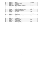
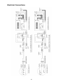
This .pdf document is bookmarked
Operating Instructions and Parts Manual
18-inch Variable Speed Drill Press
Model 2800
for serial # 7040001 and up
WALTER MEIER (Manufacturing) Inc.
427 New Sanford Road
LaVergne, Tennessee 37086
Ph.: 800-274-6848
www.powermatic.com
Part No. M-1792800
Revision C1 04/2010
Copyright © 2010 Walter Meier (Manufacturing) Inc.
Warranty and Service
Walter Meier (Manufacturer) Inc., warrants every product it sells. If one of our tools needs service or repair, one of our Authorized
Service Centers located throughout the United States can give you quick service. In most cases, any of these Walter Meier
Authorized Service Centers can authorize warranty repair, assist you in obtaining parts, or perform routine maintenance and
major repair on your POWERMATIC® tools. For the name of an Authorized Service Center in your area call 1-800-274-6848.
MORE INFORMATION
Walter Meier is consistently adding new products to the line. For complete, up-to-date product information, check with your local
Walter Meier distributor, or visit powermatic.com.
WARRANTY
POWERMATIC products carry a limited warranty which varies in duration based upon the product.
WHAT IS COVERED?
This warranty covers any defects in workmanship or materials subject to the exceptions stated below. Cutting tools, abrasives
and other consumables are excluded from warranty coverage.
WHO IS COVERED?
This warranty covers only the initial purchaser of the product.
WHAT IS THE PERIOD OF COVERAGE?
The general POWERMATIC warranty lasts for the tim e period specified in the product literature of each product.
WHAT IS NOT COVERED?
The Five Year Warranty does not cover products used for commercial, industrial or educational purposes. Products with a Five
Year Warranty that are used for commercial, industrial or education purposes revert to a One Year Warranty. This warranty does
not cover defects due directly or indirectly to misuse, abuse, negligence or accidents, normal wear-and-tear, improper repair or
alterations, or lack of maintenance.
HOW TO GET SERVICE
The product or part must be returned for examination, postage prepaid, to a location designated by us. For the name of the
location nearest you, please call 1-800-274-6848.
You must provide proof of initial purchase date and an explanation of the complaint must accompany the merchandise. If our
inspection discloses a defect, we will repair or replace the product, or refund the purchase price, at our option.
We will return the repaired product or replacement at our expense unless it is determined by us that there is no defect, or that the
defect resulted from causes not within the scope of our warranty in which case we will, at your direction, dispose of or return the
product. In the event you choose to have the product returned, you will be responsible for the handling and shipping costs of the
return.
HOW STATE LAW APPLIES
This warranty gives you specific legal rights; you may also have other rights which vary from state to state.
LIMITATIONS ON THIS WARRANTY
WALTER MEIER (MANUFACTURING) INC., LIMITS ALL IMPLIED WARRANTIES TO THE PERIOD OF THE LIMITED
WARRANTY FOR EACH PRODUCT. EXCEPT AS STATED HEREIN, ANY IMPLIED WARRANTIES OR MERCHANTABILITY
AND FITNESS ARE EXCLUDED. SOME STATES DO NOT ALLOW LIMITATIONS ON HOW LONG THE IMPLIED WARRANTY
LASTS, SO THE ABOVE LIMITATION MAY NOT APPLY TO YOU.
WALTER MEIER SHALL IN NO EVENT BE LIABLE FOR DEATH, INJURIES TO PERSONS OR PROPERTY, OR FOR
INCIDENTAL, CONTINGENT, SPECIAL, OR CONSEQUENTIAL DAMAGES ARISING FROM THE USE OF OUR PRODUCTS.
SOME STATES DO NOT ALLOW THE EXCLUSION OR LIMITATION OF INCIDENTAL OR CONSEQUENTIAL DAMAGES, SO
THE ABOVE LIMITATION OR EXCLUSION MAY NOT APPLY TO YOU.
Walter Meier sells through distributors only. The specifications in Walter Meier catalogs are given as general information and are
not binding. Members of Walter Meier reserve the right to effect at any time, without prior notice, those alterations to parts,
fittings, and accessory equipment which they may deem necessary for any reason whatsoever.
2
Table of Contents
Warranty and Service..........................................................................................................................2
Table of Contents ...............................................................................................................................3
Warning .............................................................................................................................................4
Introduction ........................................................................................................................................6
Specifications .....................................................................................................................................6
Unpacking ..........................................................................................................................................7
Contents of the Shipping Container ..................................................................................................7
Assembly ...........................................................................................................................................8
Column ...........................................................................................................................................8
Table Bracket ..................................................................................................................................8
Head Assembly ...............................................................................................................................9
Installing the Fence ....................................................................................................................... 10
Installing Arbor and Chuck ............................................................................................................. 10
Chuck and Arbor Removal ............................................................................................................. 10
Grounding Instructions ...................................................................................................................... 11
Extension Cords ............................................................................................................................ 12
Adjustments ..................................................................................................................................... 13
Table Movement ........................................................................................................................... 13
Changing Spindle Speeds .............................................................................................................. 13
Depth Stop.................................................................................................................................... 14
Return Spring ................................................................................................................................ 14
Start/Stop ..................................................................................................................................... 14
Laser Adjustment .......................................................................................................................... 15
Operation ......................................................................................................................................... 17
Installing the Bit ............................................................................................................................. 17
Positioning the Workpiece .............................................................................................................. 17
General Inspection ........................................................................................................................ 17
Setting Rotation Speed .................................................................................................................. 17
Optional Accessories ........................................................................................................................ 19
Replacement Parts ........................................................................................................................... 19
Model 2800 Drill Press ................................................................................................................... 20
Parts List: Model 2800 Drill Press ................................................................................................... 21
Electrical Connections....................................................................................................................... 25
Electrical Connections....................................................................................................................... 26
3
Warning
1. Read and understand the entire owners manual before attempting assembly or operation.
2. Read and understand the warnings posted on the machine and in this manual. Failure to comply with
all of these warnings may cause serious injury.
3. Replace the warning labels if they become obscured or removed.
4. This drill press is designed and intended for use by properly trained and experienced personnel only.
If you are not familiar with the proper and safe operation of a drill press, do not use until proper
training and knowledge have been obtained.
5. Do not use this drill press for other than its intended use. If used for other purposes, Walter Meier
(Manufacturing) Inc., disclaims any real or implied warranty and holds itself harmless from any injury
that may result from that use.
6. Always wear approved safety glasses/face shields while using this drill press. Everyday eyeglasses
only have impact resistant lenses; they are not safety glasses.
7. Before operating this drill press, remove tie, rings, watches and other jewelry, and roll sleeves up past
the elbows. Remove all loose clothing and confine long hair. Non-slip footwear or anti-skid floor strips
are recommended. Do not wear gloves.
8. Wear ear protectors (plugs or muffs) during extended periods of operation.
9. Some dust created by power sanding, sawing, grinding, drilling and other construction activities
contains chemicals known to cause cancer, birth defects or other reproductive harm. Some examples
of these chemicals are:
•
•
Lead from lead based paint.
Crystalline silica from bricks, cement and other masonry products.
•
Arsenic and chromium from chemically treated lumber.
Your risk of exposure varies, depending on how often you do this type of work. To reduce your
exposure to these chemicals, work in a well-ventilated area and work with approved safety
equipment, such as face or dust masks that are specifically designed to filter out microscopic
particles.
10. Do not operate this machine while tired or under the influence of drugs, alcohol or any medication.
11. Make certain the switch is in the OFF position before connecting the machine to the power supply.
12. Make certain the machine is properly grounded.
13. Make all machine adjustments or maintenance with the machine unplugged from the power source.
14. Remove adjusting keys and wrenches. Form a habit of checking to see that keys and adjusting
wrenches are removed from the machine before turning it on.
15. Keep safety guards in place at all times when the machine is in use. If removed for maintenance
purposes, use extreme caution and replace the guards immediately.
16. Check damaged parts. Before further use of the machine, a guard or other part that is damaged
should be carefully checked to determine that it will operate properly and perform its intended
function. Check for alignment of moving parts, binding of moving parts, breakage of parts, mounting
and any other conditions that may affect its operation. A guard or other part that is damaged should
be properly repaired or replaced.
17. Provide for adequate space surrounding work area and non-glare, overhead lighting.
18. Keep the floor around the machine clean and free of scrap material, oil and grease.
19. Keep visitors a safe distance from the work area. Keep children away.
20. Make your workshop child proof with padlocks, master switches or by removing starter keys.
4
21. Give your work undivided attention. Looking around, carrying on a conversation and “horse-play” are
careless acts that can result in serious injury.
22. Maintain a balanced stance at all times so that you do not fall or lean against the drill bit or other
moving parts. Do not overreach or use excessive force to perform any machine operation.
23. Use the right tool at the correct speed and feed rate. Do not force a tool or attachment to do a job for
which it was not designed. The right tool will do the job better and safer.
24. Use recommended accessories; improper accessories may be hazardous.
25. Maintain tools with care. Keep bits sharp and clean for the best and safest performance. Follow
instructions for lubricating the machine and changing accessories.
26. Whenever possible, use the fence. Also use jigs or fixtures where needed to secure the workpiece. A
drill bit can seize up, causing the workpiece to rotate with the spindle and can cause injury.
27. Turn off the machine and disconnect from power before cleaning. Use a brush or compressed air to
remove chips or debris — do not use your hands.
28. Do not stand on the machine. Serious injury could occur if the machine tips over.
29. Never leave the machine running unattended. Turn the power off and do not leave the machine until it
comes to a complete stop.
30. Remove loose items and unnecessary work pieces from the area before starting the machine.
Familiarize yourself with the following safety notices used in this manual:
This means that if precautions are not heeded, it may result in minor injury and/or
possible machine damage.
even death.
This means that if precautions are not heeded, it may result in serious injury or possibly
- - SAVE THESE INSTRUCTIONS - -
5
Introduction
This manual is provided by Walter Meier (Manufacturing) Inc., covering the safe operation and
maintenance procedures for a Powermatic Model 2800 Drill Press. This manual contains instructions on
installation, safety precautions, general operating procedures, maintenance instructions and parts
breakdown. This machine has been designed and constructed to provide years of trouble free operation if
used in accordance with instructions set forth in this manual. If there are any questions or comments,
please contact either your local supplier or Walter Meier. Walter Meier can also be reached at our web
site: www.wmhtoolgroup.com.
Specifications
Model Number .............................................................................................................................. 2800
Stock Number .........................................................................................................................1792800
Swing (in.) ........................................................................................................................................ 18
Maximum Drilling Capacity (in.) ........................................................................................................ 5/8
Chuck Size (in.) ............................................................................................................................... 5/8
Spindle Travel (in.)........................................................................................................................ 4-3/8
Maximum Spindle to Table Distance (in.)...................................................................................... 26-1/2
Maximum Spindle to Base Distance (in.) ............................................................................................ 47
Table Size (LxW)(in.) .................................................................................................................16 x 14
Table Size Fully Extended (LxW)(in.) ..........................................................................................16 x 26
Spindle Taper ....................................................................................................................... MT2 x JT3
Column Diameter (in.) ................................................................................................................... 3-1/8
Range of Spindle Speed (RPM) ........................................................................................... 400 to 3000
Base Size (in.) ............................................................................................................... 11-7/8 x 19-5/8
Motor ........................................................................................ TEFC, 1HP, 115/230V (pre-wired 115V)
Overall Dimensions (HxWxD)(in.)............................................................................. 68-1/2 x 20 x 31-1/2
Approximate Net Weight (lbs.) ......................................................................................................... 209
Approximate Shipping Weight (lbs.) ................................................................................................. 230
The above specifications were current at the time this manual was published, but because of our policy of
continuous improvement, Walter Meier reserves the right to change specifications at any time and without
prior notice, without incurring obligations.
6
The smaller accessories are shown in Figure 1:
3 Downfeed Handles (A)
1 Chuck (B)
1 Drift Key (C)
1 Arbor (D)
1 Shift Knob (E)
1 Locking Handle (F)
2 Lock Knobs (G)
2 T-Nuts (G)
2 Flat Washers (G)
2 Socket Head Cap Screws, M6x12 (G)
2 Hex Nuts, M6 (G)
1 Worm (H)
1 Large Handle (I)
4 Hex Cap Screws, M10x40 (J)
3 Hex Wrenches, 3, 5 and 6mm (K)
1 Dust Port (L)
1 Fence Assembly (M)
1 Owner's Manual (not shown)
1 Warranty Card (not shown)
Unpacking
Open shipping container and check for shipping
damage. Report any damage immediately to
your distributor and shipping agent. Do not
discard any shipping material until the Drill Press
is assembled and running properly.
Compare the contents of your container with the
following parts list to make sure all parts are
intact. Missing parts, if any, should be reported
to your distributor. Read the instruction manual
thoroughly for assembly, maintenance and
safety instructions.
Contents of the Shipping Container
1
1
1
1
Column Assembly with Rack and Ring
Head Assembly
Base
Table Bracket and Table
Figure 1
Read and understand the entire contents of this manual before attempting set-up
or operation! Failure to comply may cause serious injury.
7
Assembly
Tools required for assembly:
Rubber mallet
17mm open-end ,or socket, wrench
Set of hex (Allen) wrenches
Exposed metal surfaces on the drill press have
been factory-coated with a protectant. Remove
this with a soft rag moistened with a light
solvent. Do not use an abrasive pad and do not
use gasoline, paint thinner or acetone, as these
will damage plastic components and painted
surfaces.
The drill press should be placed in a dry area
with a level floor and good lighting. Provide
enough space around the drill press to allow for
operations and any adjustments or servicing.
Assembly is a two person
operation to avoid injury from accidental
dropping.
Figure 2
Column
Referring to Figure 2:
1. Place the base (Figure 2) upon a level floor.
It may be secured to the floor with lag
screws (not provided) through the four holes
in the base.
2. If you do not wish to permanently secure the
drill press to the floor, it can be bolted to a
plywood panel which will serve as its base
and further stabilize it. Use a high grade of
plywood at least 3/4" thick. It should be
large enough to prevent vibration, sliding or
moving of the drill press during operation.
Do not use a mobile base with this machine.
3. Attach the column assembly to the base
with four M10x40 hex cap screws, and
tighten with a 17mm wrench.
Figure 3
(table shown removed)
Table Bracket
When shipped, the ring and rack are bundled
together with the column in plastic wrap.
Referring to Figures 3 through 6:
1. Remove the wrap and take the ring from the
column by loosening the set screw and
sliding the ring off. Also remove the rack.
See Figure 4.
2. Position the worm through the hole in the
table bracket (Figure 3) and push it as far as
it will go until the shaft protrudes and the
worm is meshed with the gear, as shown.
Figure 4
8
NOTE: The table can be removed if desired
to make handling the bracket easier,
through this is not necessary for installation.
To remove the table, loosen and remove the
bolt holding table to bracket.
3. Position the rack into the slot in the table
bracket, meshing the rack teeth with the
worm gear.
4. Hold the rack in the slot, while setting the
table bracket over the column. Then slide
table bracket and rack together down the
column.
Figure 5
5. The lower end of the rack should rest in the
lip of the holder, as shown in Figure 6.
6. Slide the large handle onto the protruding
shaft of the worm (Figure 5), and tighten the
set screw in the handle with a 3mm hex
wrench. Crank the handle counterclockwise
to lower the table bracket down the column.
7. Place the ring onto the column and slide it
down over the top edge of the rack (see
Figure 4). Tighten the set screw on the ring.
8. Screw the locking handle into the table
bracket (Figure 5) and tighten the locking
handle to secure the table bracket’s position
on the column.
Figure 6
Head Assembly
Referring to Figures 7 and 8:
1. With the help of an assistant, mount the
head assembly to the column, and tighten
the two set screws with a 5mm hex wrench.
See Figure 7.
2. Screw the three downfeed handles into the
threaded holes in the hub. These can be
mounted to either side of the head for your
convenience. Tighten the hex nuts against
the hub.
Figure 7
3. Insert the shift knob into the collar on the
side by screwing it in clockwise (Figure 8).
Figure 8
9
Installing the Fence
Referring to Figure 9:
Slide the fence assembly into the T-slots on the
table. The fence assembly is secured by
tightening the knobs (A. The fence can be
expanded by loosening the smaller knobs (B)
and sliding the fence halves outward. Tighten all
four knobs on the fence assembly before
operating the drill press.
A dust chute (2” diameter) is mounted to the
fence assembly for attaching a dust collection
system. The fence halves must be in the
expanded position to provide an opening for
dust exhaust.
Figure 9
Installing Arbor and Chuck
Referring to Figure 10:
1. Disconnect machine from power source.
2. Thoroughly clean the entire arbor and the
inside of the chuck (Figure 10) with a soft
rag and solvent such as mineral spirits. Any
grease or residue in these areas can cause
the pieces to separate and create a safety
hazard as well as damage to the tool.
3. Slide arbor up into the spindle.
4. Firmly push the chuck by hand onto the
taper of the arbor.
5. Make sure the jaws of the chuck are opened
all the way until they are inside the chuck
body. Use a single tap from a rubber mallet,
or a hammer and a block of wood, against
the bottom of the chuck to seat the chuck
securely onto the arbor.
Figure 10
Do not use a steel hammer
directly against the chuck, as this may
damage the chuck.
Chuck and Arbor Removal
Referring to Figure 11:
1. Disconnect machine from power source.
2. Lower the quill assembly with the downfeed
handles to expose the slot.
3. Insert the drift key into the slot.
4. Tap the drift key into the slot until the chuck
and arbor fall out. NOTE: Hold onto the
chuck to prevent it being damaged as it
falls.
Figure 11
10
Grounding Instructions
Electrical connections must
be made by a qualified electrician in
compliance with all relevant codes. This
machine must be properly grounded to help
prevent electrical shock and possible fatal
injury.
In the event of a malfunction or breakdown,
grounding provides a path of least resistance for
electric current to reduce the risk of electric
shock. This machine is equipped with an electric
cord having an equipment-grounding conductor
and a grounding plug. The plug must be plugged
into a matching outlet that is properly installed
and grounded in accordance with all local codes
and ordinances. Do not modify the plug provided
– if it will not fit the outlet, have the proper outlet
installed by a qualified electrician.
Improper connection of the equipmentgrounding conductor can result in a risk of
electric shock. The conductor with insulation
having an outer surface that is green with or
without yellow stripes is the equipmentgrounding connector.
If repair or replacement of the electric cord or
plug is necessary, do not connect the
equipment-grounding conductor to a live
terminal.
Check with a qualified electrician or service
personnel if the grounding instructions are not
completely understood, or if in doubt as to
whether the tool is properly grounded.
Use only 3-wire extension cords that have 3prong grounding plugs and 3-pole receptacles
that accept the machine’s plug.
It is recommended that the PM2800 Drill Press
be connected to a grounded, minimum 20 amp
circuit with a minimum 20 amp circuit breaker or
time delay fuse. Local codes take precedence
over recommendations.
Repair or replace damaged or worn cord
immediately.
115 Volt Operation
As received from the factory, your drill press is
ready to operate at 115-volt operation. This drill
press, when wired for 115 volt, is intended for
use on a circuit that has an outlet that looks like
the one illustrated in Figure 12. The tool has a
grounding plug that looks like the plug illustrated
in Figure 12.
Figure 12
11
A temporary adapter, similar to the one in Figure
13, may be used to connect this plug to a 2-pole
receptacle if a properly grounded outlet is not
available. The temporary adapter should only be
used until a properly grounded outlet can be
installed by a qualified electrician. This adapter
is not applicable in Canada.
The green-colored rigid ear, lug, and the like,
extending from the adapter must be connected
to a permanent ground such as a properly
grounded outlet box.
Figure 13
230 Volt Operation
If 230V, single phase operation is desired, the
following instructions must be performed:
1. Disconnect the machine from the power
source.
2. The drill press motor has four leads that are
factory connected for 115V operation. For
230V operation, re-connect the leads as
shown in the diagrams on pages 25 and 26.
3. The 115V attachment plug supplied with the
drill press must be replaced with a UL/CSA
listed plug suitable for 230V operation,
similar to the plug illustrated in Figure 14.
Contact your local Authorized Powermatic
Service Center or qualified electrician for
proper procedures to install the plug.
4. The drill press must comply with all local
and national codes after the 230 volt plug is
installed.
Figure 14
5. The drill press with a 230-volt plug should
only be connected to an outlet having the
same configuration as shown in Figure 14.
No adapter is available or should be used
with the 230-volt plug.
Recommended Gauges (AWG) of Extension Cords
Extension Cord Length *
Extension Cords
If an extension cord is necessary, make sure the
cord rating is suitable for the amperage listed on
the machine's motor plate. An undersize cord
will cause a drop in line voltage resulting in loss
of power and overheating.
The chart in Figure 15 shows the correct size
cord to use based on cord length and motor
plate amp rating. If in doubt, use the next
heavier gauge. The smaller the gauge number,
the heavier the cord.
Amps
25
feet
50
feet
75
feet
100
feet
150
feet
200
feet
<5
16
16
16
14
12
12
5 to 8
16
16
14
12
10
NR
8 to 12
14
14
12
10
NR
NR
12 to 15
12
12
10
10
NR
NR
15 to 20
10
10
10
NR
NR
NR
21 to 30
10
NR
NR
NR
NR
NR
*based on limiting the line voltage drop to 5V at 150% of the
rated amperes.
NR: Not Recommended.
Figure 15
12
Adjustments
Table Movement
To raise or lower the table:
Loosen the column locking handle (shown in
Figure 5). Turn large handle to raise or lower the
table along the column rack. Re-tighten the
column locking handle before attempting to drill.
To swing table around the column:
When drilling into a long workpiece, swing the
table out of the way and use the drill press base
as your table. Slots in the base can be used to
mount work holding devices.
Figure 16
1. Loosen the column locking handle (shown in
Figure 5).
2. Swing table to desired position. If the rack
tends to bind, you will need to nudge the top
or bottom end of the rack around the column
while swinging the table.
3. Tighten the column locking handle.
To tilt table:
Referring to Figures 16 and 17:
1. To tilt the table, loosen the bolt (A) slightly
and pull out on the indicator pin (B). The
indicator pin will engage at 0, 45 and 90
degree positions of the table.
Figure 17
2. Pivot the table to desired angle by aligning
the scale (in degrees) on the table to the
line on the table bracket (Figure 17).
3. Re-tighten bolt (A, Figure 16).
Table Extensions
Loosen the handles (C, Figure 16) and slide the
extensions outward, then re-tighten the handles.
Changing Spindle Speeds
Change speeds only while
the drill press is running.
With the drill press running, rotate the shift knob
(Figure 18) slightly counterclockwise to loosen it,
then push the handle left or right until the
desired speed is displayed on the LED readout
at the front of the head. Tighten the shift knob
clockwise to secure the setting.
Figure 18
13
Depth Stop
The depth stop is useful for repetitive drilling of
holes of the same depth.
Referring to Figure 19:
1. Measure the distance from the tip of the drill
bit to the workpiece. Add to this the desired
depth of the hole in the workpiece.
2. Rotate the bottom nut (A, Figure 19) to this
measurement on the accompanying scale.
3. Bring the top nut (B, Figure 19) flush with
the bottom nut. This will prevent any
movement of the bottom nut as it contacts
the seat (C, Figure 19).
Alternatively, for less precise drilling, you can
lower the bit to the desired depth, as shown in
Figure 19, and tighten both nuts (A and B)
against the seat (C).
Return Spring
Figure 19
The tension of the return spring (which raises
the spindle after drilling) has been pre-set at the
factory. No further adjustment should be
attempted unless absolutely necessary. Should
it become necessary, proceed as follows.
Referring to Figure 20:
1. Disconnect machine from power source.
2. Pry off the cap (A, Figure 20) and remove
the hex nut and two washers (B). Pull off the
hub (C).
3. Loosen the two inner hex nuts (D) Do not
remove.
Figure 20
4. Pull out slightly the coil spring cover (E)
while firmly holding it. DO NOT allow the
coil spring cover to turn freely in your
hand, or the spring will unwind.
5. Rotate the coil spring cover until the tab (F)
on the spring retainer engages the next
notch in the coil spring cover. Rotate the coil
spring cover counterclockwise to increase
spring tension, clockwise to decrease.
6. Make sure the coil spring cover is pushed
back in, then tighten the two hex nuts (D).
Do not over tighten. The hex nuts should be
tightened against each other.
7. Re-install hub, washers, hex nut and cap.
Start/Stop
Power Indicator Light – The start switch has a
power indicator lamp which is on whenever
there is power connected to the Drill Press,
not just when the Drill Press is running.
14
Do not assume that no light means there is no
power to the machine. If the bulb is bad, there
will be no indication. Always check before use.
Do not rely that no light
means no power to the machine. Always
check for power first. Failure to comply may
cause serious injury!
Referring to Figure 21:
Start – Press the green start switch.
When power is connected to the machine, the
green light is always on regardless of whether
the Drill Press is running or not.
Figure 21
Stop – Press the red switch to stop.
Reset – In the event that the Drill Press stops
without pressing the stop button, as the result of
a tripped fuse or circuit breaker, etc.:
1. Press red button to reset main switch.
2. Press the green button to restart the
machine.
Safety - The switch has a safety feature that
prevents unauthorized or accidental starting of
the drill press. With the switch in the "off"
position, slide out the switch safety key (Figure
21). This piece must be re-inserted before the
drill press can operate.
Figure 22
Laser Adjustment
(Figures 22 through 25)
Do not look directly into the
laser beam or view it directly with optical
instruments. See Figure 22.
The Laser Assembly has been installed and preset at the factory. It should, however, be
checked and any adjustments made before
operating the drill press. It should also be rechecked periodically, as constant machine
vibration may cause it to become misaligned.
Figure 23
1. Remove the guards (item 184, page 20) to
access the laser assemblies.
2. Take a length of board (Q) and draw a
perpendicular line (N) on one side using a
square.
3. Place a small drill bit (K) in the chuck (L),
then place the board (Q) on the table on
edge against the drill bit with the markedline side toward the back of the drill press.
Important: The table should be in horizontal
position and locked. Verify that the line (N,
Figure 24) is perpendicular to the table.
Figure 24
15
4. Connect power to the drill press, and turn on
the laser using the button at the front of the
drill press head.
Vertical Alignment
5. Manually rotate the laser assembly (A2) and
move the board from side to side as
required until the laser light (M) lines up with
the board marking (N) to look like (O). Then
carefully tighten the three setscrews (E).
Repeat step 5, if necessary, until the light
and marking are aligned.
6. Adjust the other laser in the same manner.
Two parallel laser markings should look like
O and P in Figure 24 – the distance
between the lines will vary with board
thickness; however, the lines must be
parallel.
Figure 24 (repeated)
Cross Hair Alignment
7. Place board (R) flat on the table. Do not
allow the board to move from this position;
use clamps if needed. Bring the bit down
until it leaves a slight perforation in the
board; then raise it back up.
8. Loosen one laser setscrew (F, Fig. 23) and
adjust (G, Fig. 23) so the laser line crosses
the perforation (S). Tighten setscrew (F).
9. Adjust the other laser assembly in the same
manner until the laser lines form cross
hairs (S) exactly over the perforation in the
board.
10. Tighten setscrew (F, Fig, 23). Re-check the
vertical alignment to insure that the laser
lines did not shift during the tightening
process.
Figure 25
The laser is now calibrated properly and the
location of your holes can be centered at the
cross hairs for accurate drilling.
11. Assemble guards with pan head screws
over the laser on each side.
16
Setting Rotation Speed
Operation
There are several factors which determine the
best speed to use in any drill press operation,
such as kind of material being worked, size of
hole, type of drill, and quality of cut desired.
Installing the Bit
Insert the bit (not provided) into the chuck jaws
with about 1” insertion. When using a small bit,
do not insert it so far that the jaws touch the
flutes of the bit. Make sure the bit is centered in
the chuck before tightening the chuck. The
chuck is a keyless model; simply rotate it by
hand to tighten the bit.
A general rule of thumb is, the smaller the drill,
the greater the required RPMs. And the speed
should be faster for soft materials and slower for
harder materials.
Maintenance
Before doing maintenance on
the machine, disconnect it from the electrical
supply by pulling out the plug or switching
off the main switch! Failure to comply may
cause serious injury.
Positioning the Workpiece
Whenever possible, use
clamps or work hold-downs to secure the
workpiece to the table.
Always secure the workpiece to prevent it being
torn from the operator’s hand. Using the column
as a work stop is not recommended; instead,
use holding devices such as clamps. When
using the table in tilted position, make sure the
table is securely tightened and the workpiece is
clamped sufficiently.
After each use, clean sawdust from the table
with a brush (do not use your hands).
For clean, splinter-free holes, place a piece of
scrap wood on the table below the workpiece.
Check that bolts are tight and electrical cords
are in good condition. Belts should be in good
condition and tensioned properly. Occasional
dressing of the belts with spray can type belt
dressing or paraffin wax will promote longer belt
life and quieter operation.
Occasionally apply a light film of oil to the quill
and column. This will reduce wear, prevent rust
and assure ease of operation.
Apply grease to the rack on the column.
Perform operations with a minimum extension of
the quill. Adjust table position rather than using
excessive quill travel.
Feed the bit into the material with only enough
force to allow the bit to work. Feeding too slowly
may cause burning of the workpiece. Feeding
too quickly may cause the motor to stop and/or
the bit to break.
Bearings on the drill press are self-contained
and permanently
lubricated;
no further
lubrication is needed.
Exposed metal surfaces of the table and base
should be kept clean and free of rust. Apply a
good quality paste wax. Avoid any wax that
contains silicone or other synthetic ingredients.
These materials can find their way into lumber
and can make staining and finishing difficult.
General Inspection
Before each operation of your Model 2800 drill
press, make a habit of checking that all locking
handles, set screws, bolts, etc., are tight on the
table and head. Confirm that the drill bit is
securely inserted inside the chuck jaws.
The quill return spring should receive SAE 20 oil
once yearly. Apply the oil beneath the coil spring
cover (E, Figure 20) using a squirt can.
Clear all items, such as tools and rags, away
from the machine.
Before attempting regular work, get the feel of
the drill press by practicing on scrap material.
For best results, always use sharp bits and
proper feed rates.
17
Troubleshooting
Trouble
Drill press will not
start.
Drill press does not
come up to speed.
Excessive vibration.
Motor stalls.
;Noisy Operation.
Noisy Operation
(cont.)
Wood splinters on the
underside.
Drill or tool heats up
or burns workpiece.
Drill bit wanders.
Probable Cause
Remedy
Not connected to power.
Check all plug connections.
Fuse blown, or circuit breaker tripped.
Replace fuse, or reset circuit breaker.
Cord damaged.
Replace cord.
Extension cord too light or too long.
Replace with adequate size and
length cord.
Low current.
Contact a qualified electrician.
Improper belt tension.
Adjust belt tension.
Uneven belt wear (hard spots).
Replace belt.
Motor or spindle pulley out of balance.
Balance or repair problem pulley.
Motor malfunction.
Have motor tested by a qualified
service center. Repair or replace as
necessary.
Overfeeding the bit.
Reduce feed rate.
Dull bit.
Sharpen or replace bit.
Motor not reaching running speed.
Repair or replace motor.
Motor is malfunctioning.
Have motor tested by a qualified
service center. Repair or replace as
necessary.
Excessive vibration.
See “Excessive Vibration” above.
Incorrect belt tension.
Adjust belt tension.
Dry spindle.
Lubricate spindle.
Loose pulleys.
Make any needed corrections.
Noisy motor.
Check motor bearings or for loose
motor fan.
No backing board used.
Place a scrap board beneath the
workpiece to prevent splintering.
Excessive speed.
Reduce speed.
Chips not clearing from hole or bit.
Retract drill bit frequently to remove
chips.
Dull drill bit.
Resharpen, or replace drill bit.
Feeding the bit too slowly.
Increase feed rate.
Rotation of bit incorrect.
Reverse motor rotation (refer to
diagrams on pages 25 and 26).
Bit sharpened incorrectly.
Resharpen bit correctly.
Bent drill bit.
Replace bit.
18
Trouble
Drill bit binds in
workpiece.
Probable Cause
Remedy
Bit or chuck not installed properly.
Reinstall the chuck, or bit properly.
Workpiece pinching the bit.
Support or clamp workpiece.
Excessive feed rate.
Decrease feed rate.
Chuck jaws not tight.
Tighten chuck jaws.
Improper belt tension.
Adjust belt tension.
Optional Accessories
JW1000
Reducer, 4" to 2-1/4" O.D. – 2"I.D.
Replacement Parts
Replacement parts are listed on the following pages. To order parts or reach our service department, call
1-800-274-6848 Monday through Friday (see our website for business hours, www.powermatic.com).
Having the Model Number and Serial Number of your machine available when you call will allow us to
serve you quickly and accurately.
19
Model 2800 Drill Press
20
Parts List: Model 2800 Drill Press
Index No. Part No.
Description
Size
Qty
1 .............. PM2800-001............Strain Relief ....................................................................................... 2
2 .............. TS-1482051 ............Hex Cap Screw ................................................M6x25........................ 4
3 .............. PM2800-003............Retaining Plate ................................................................................... 1
4 .............. TS-1490031 ............Hex Cap Screw ................................................M8x20........................ 4
5 .............. TS-1550061 ............Flat Washer......................................................M8 ............................. 4
6 .............. TS-1533052 ............Pan Head Screw...............................................M5x16........................ 2
7 .............. PM2800-007............Cord Clamp ........................................................................................ 2
8 .............. TS-1534052 ............Phillips Pan Head Machine Screw......................M6x16........................ 2
9 .............. PM2800-009............Lower Pulley Cover ............................................................................. 1
10 ............ TS-0680021 ............Flat Washer......................................................1/4” ............................ 4
11 ............ PM2800-011............Strain Relief ....................................................................................... 1
12 ............ TS-1503041 ............Socket Head Cap Screw ...................................M6x16........................ 1
13 ............ PM2800-013............Motor ..............................................................1HP,115/230V,1Ph ..... 1
................ PM2800-013MF .......Motor Fan (not shown) ........................................................................ 1
................ PM2800-013MFC-2 .Motor Fan Cover (not shown) .............................................................. 1
................ PM2800-013SC .......Starting Capacitor (not shown)...........................400uF, 125VAC .......... 1
................ PM2800-013CS .......Centrifugal Switch (not shown) ............................................................ 1
14 ............ TS-1503031 ............Socket Head Cap Screw ...................................M6x12........................ 1
15 ............ TS-0680021 ............Flat Washer......................................................1/4” ............................ 1
16 ............ PM2800-016............Spring Cap ......................................................................................... 1
17 ............ PM2800-017............Variable Speed Belt ..........................................17x8x776 mm............. 1
18 ............ PM2800-018............Pulley................................................................................................. 2
19 ............ PM2800-019............Compression Spring ........................................................................... 2
20 ............ PM2800-020............Shaft Sleeve ....................................................................................... 1
21 ............ PM2800-021............Key ..................................................................5x5x35 mm ................ 2
22 ............ PM2800-022............C-Ring .............................................................A-30........................... 2
23 ............ PM2800-023............Set Bolt .............................................................................................. 2
24 ............ PM2800-024............Center Pulley Assembly ...................................................................... 1
25 ............ PM2800-025............C-Ring .............................................................B-35 .......................... 1
26 ............ BB-6202ZZ ..............Ball Bearing......................................................6202ZZ ...................... 2
27 ............ PM2800-027............Collar ................................................................................................. 1
28 ............ PM2800-028............Center Shaft ....................................................................................... 1
29 ............ PM2800-029............Center Pulley...................................................................................... 1
30 ............ PM2800-030............Post ................................................................................................... 1
31 ............ TS-1524011 ............Set Screw ........................................................M8x8 ......................... 2
32 ............ PM2800-032............Speed Bar Seat .................................................................................. 1
33 ............ PM2800-033............Stud ................................................................................................... 1
34 ............ TS-1534052 ............Pan Head Screw...............................................M6x16........................ 1
35 ............ PM2800-035............Washer .............................................................................................. 1
36 ............ PM2800-036............Guide ................................................................................................. 1
37 ............ PM2800-037............Drive Screw......................................................Ø2.3-5 mm ................. 8
38 ............ TS-1525021 ............Socket Set Screw .............................................M10x12 ...................... 2
39 ............ PM2800-039............Spring Pin ........................................................M6x25........................ 2
40 ............ PM2800-040............Head.................................................................................................. 1
41 ............ PM2800-041............Shaft Seat .......................................................................................... 1
42 ............ PM2800-042............Spring Retainer .................................................................................. 1
43 ............ PM2800-043............Coil Spring ......................................................................................... 1
44 ............ PM2800-044............Spring Cap ......................................................................................... 1
................ PM2800-044A .........Coil Spring Assembly (includes index # 43 and 44) ............................... 1
45 ............ PM2800-045............Cushion ...........................................................30×21-2 mm ............... 1
46 ............ TS-0561052 ............Hex Nut............................................................1/2”-20UNF ................ 1
47 ............ TS-0571052 ............Hex Jam Nut ....................................................1/2”-20UNF ................ 1
48 ............ PM2800-048............Hub ................................................................................................... 1
49 ............ TS-2360121 ............Flat Washer......................................................M12 ........................... 2
50 ............ TS-0720111 ............Lock Washer ....................................................1/2” ............................ 1
51 ............ TS-0561052 ............Hex Nut............................................................1/2”-20UNF ................ 1
52 ............ PM2800-052............Cover ................................................................................................. 1
21
53 ............ PM2800-053............Quill Set Screw .................................................M10x1.5-2A................ 1
54 ............ TS-1540071 ............Hex Nut............................................................M10 ........................... 1
55 ............ PM2800-055............Rack Ring Assembly ........................................................................... 1
56 ............ TS-1523021 ............Socket Head Set Screw ....................................M6x8 ......................... 1
57 ............ PM2800-057............Rack Ring .......................................................................................... 1
58 ............ PM2800-058............Lead Wire Assembly .........................................26AWG*2C-550MM .... 2
59 ............ PM2800-059............Locking Cable Tie .............................................A-085S ...................... 1
60 ............ PM2800-060............Gear .................................................................................................. 1
61 ............ PM2800-061............Worm................................................................................................. 1
62 ............ PM2800-037............Drive Screw......................................................Ø2.3-5 mm ................. 2
63 ............ PM2800-063............Centering Scale .................................................................................. 1
64 ............ PM2800-064............Crank Arm.......................................................................................... 1
65 ............ PM2800-065............Crank Arm Handle ............................................M10 ........................... 1
66 ............ PM2800-037............Drive Screw......................................................Ø2.3-5 mm ................. 2
67 ............ PM2800-067 ...........Tilt Angle Scale .................................................................................. 1
68 ............ PM2800-068............Gear Shaft ......................................................................................... 1
69 ............ PM2800-069A .........Table Bracket ..................................................................................... 1
70 ............ PM2800-070............Column Lock Handle.........................................M12x35 ...................... 1
71 ............ PM2800-071............Rack ................................................................108T .......................... 1
72 ............ PM2800-072............Column .............................................................................................. 1
73 ............ TS-1525021 ............Set Screw ........................................................M10x12 ...................... 1
74 ............ TS-1491061 ............Hex Cap Screw ................................................M10x40 ...................... 4
75 ............ PM2800-075............Column Holder ................................................................................... 1
76 ............ PM2800-076............Base .................................................................................................. 1
77 ............ PM2800-077............Locking Knob ..................................................................................... 2
78 ............ PM2800-078............Dust Port............................................................................................ 1
79 ............ PM2800-079............Knob .................................................................................................. 2
80 ............ PM2800-080............Carriage Bolt ....................................................M6x20........................ 2
81 ............ PM2800-081............Fence ................................................................................................ 2
82 ............ PM2800-082............Nut ..................................................................5/8”-11 ....................... 1
83 ............ PM2800-083............Hex Bolt ...........................................................5/8”-11x2-3/8”............. 1
84 ............ PM2800-084............Alignment Bolt Assembly ..................................................................... 1
85 ............ PM2800-085............Table Insert ........................................................................................ 1
86 ............ PM2800-086............Fence Body ........................................................................................ 1
87 ............ TS-1540041 ............Hex Nut............................................................M6 ............................. 2
88 ............ PM2800-088............Washer ............................................................8x15-1 mm ................. 2
89 ............ TS-1503031 ............Socket Head Cap Screw ...................................M6x12........................ 2
................ PM2800-TBA* .........Table and Bracket Assembly [only serial # 7040000 and previous]......... 1
(includes index # 60, 62, 63, 68, 69, 82, 83, 84, 90 and 91)
90 ............ PM2800-090A .........Table ................................................................................................. 1
91 ............ PM2800-091A .........Table Extension Wing ......................................................................... 2
92 ............ PM2800-092............T-Nut ................................................................................................. 2
93 ............ PM2800-093............Slide Tube.......................................................................................... 4
94 ............ PM2800-094............Pan Head Tapping Screw..................................M5x10........................ 4
95 ............ PM2800-095............Pan Head Tapping Screw..................................M6x25........................ 8
96 ............ PM2800-096............Grounding Sticker ............................................................................... 1
97 ............ PM2800-097............Tooth Washer...................................................M5 ............................. 2
98 ............ TS-1533032 ............Phillips Pan Head Machine Screw......................M5x10........................ 2
99 ............ PM2800-99..............Lead Wire Assembly .........................................14AWG 2.0-160L ........ 1
100 .......... PM2800-100............Truss Head Tapping Screw ...............................M3x8 ......................... 4
101 .......... PM2800-101............Controller Assembly ..........................................115/230V, 60HZ ......... 1
102 .......... PM2800-102............Lead Wire Assembly .........................................14AWG 2.0-160L ........ 1
103 .......... PM2800-103............Push-Pull Type Switch Assembly .......................125V, 20A, 1Ph .......... 1
103-1 ....... PM2800-103-1 .........Switch Safety Key ............................................................................... 1
................ PM2800-103SL........Switch Label (not shown) .................................................................... 1
104 .......... PM2800-104............Pan Head Tapping Screw..................................M5x16........................ 4
105 .......... PM2800-105............Switch Box ......................................................................................... 1
106 .......... TS-1533052 ............Phillips Pan Head Machine Screw......................M5x16........................ 3
*
Drill Presses serial # 7040000 and previous, must use complete Table and Bracket Assembly PM2800-TBA. For Drill Presses
serial # 7040001 and up, order the individual parts as listed.
22
107 .......... PM2800-107............LED Lamp Assembly .......................................................................... 2
108 .......... PM2800-108............LED Lamp Cover ................................................................................ 2
109 .......... PM2800-109............Feed Shaft Assembly .......................................................................... 1
110 .......... PM2800-110............Feed Shaft ......................................................................................... 1
111 .......... PM2800-111............Ring ................................................................................................... 1
112 .......... PM2800-112............Hub ................................................................................................... 1
113 .......... PM2800-113............Spring Pin .......................................................................................... 1
114 .......... TS-1533032 ............Phillips Pan Head Machine Screw......................M5x10........................ 1
115 .......... PM2800-115............Truss Head Tapping Screw ...............................M2x8 ......................... 2
116 .......... PM2800-116............Photo Interrupt Module ........................................................................ 1
117 .......... PM2800-117............Bracket .............................................................................................. 1
118 .......... PM2800-118............Washer .............................................................................................. 1
119 .......... PM2800-119............Stop Nut...........................................................M16 ........................... 2
120 .......... PM2800-120............Depth Stop Bolt & Scale Assembly ...................................................... 1
121 .......... PM2800-037............Drive Screw......................................................Ø2.3-5 mm ................. 2
122 .......... PM2800-122............Scale ...............................................................4-3/8 Inch ................... 1
123 .......... PM2800-123............Depth Stop Bolt .................................................................................. 1
124 .......... TS-1534092 ............Phillips Pan Head Machine Screw......................M6x35........................ 2
125 .......... PM2800-125............Plunge Housing .................................................................................. 1
126 .......... PM2800-126............Circular Nut ........................................................................................ 1
127 .......... TS-1540071 ............Hex Nut............................................................M10 ........................... 1
128 .......... PM2800-128............Set Collar ........................................................................................... 1
129 .......... TS-1504051 ............Socket Head Cap Screw ...................................M8x25........................ 1
130 .......... PM2800-130............Spindle Nut ........................................................................................ 1
131 .......... PM2800-131............Nut Lock ............................................................................................ 1
132 .......... PM2800-132............Washer .............................................................................................. 1
133 .......... BB-6203ZZ ..............Ball Bearing......................................................6203ZZ ...................... 1
134 .......... PM2800-134............Rubber Washer .................................................................................. 1
135 .......... PM2800-135............Quill ................................................................................................... 1
136 .......... PM2800-136............Drift Key ............................................................................................. 1
137 .......... BB-6205ZZ ..............Ball Bearing......................................................6205ZZ ...................... 1
138 .......... PM2800-138............Spindle .............................................................................................. 1
139 .......... PM2800-139............Spindle Assembly ............................................................................... 1
140 .......... PM2800-140............Arbor ...............................................................MT2xJT3 .................... 1
141 .......... PM2800-141............Keyless Chuck..................................................RJ3-16L ..................... 1
142 .......... PM2800-142............Slide Base Assembly .......................................................................... 4
143 .......... PM2800-143............Slide Base.......................................................................................... 1
144 .......... PM2800-144............Clamp Handle .................................................................................... 1
145 .......... PM2800-145............Bolt .................................................................................................... 1
146 .......... PM2800-146............Cushion ............................................................................................. 1
147 .......... PM2800-147............Spring Pin ........................................................M5x20........................ 1
148 .......... TS-1541011 ............Nylon Lock Hex Nut ..........................................M5 ............................. 1
149 .......... TS-1533042 ............Phillips Pan Head Machine Screw......................M5x12........................ 8
150 .......... PM2800-150............Drive Sleeve Assembly ....................................................................... 1
151 .......... PM2800-151............Drive Sleeve ....................................................................................... 1
152 .......... PM2800-152............Collar ................................................................................................. 1
153 .......... BB-6205ZZ ..............Ball Bearing......................................................6205ZZ ...................... 2
154 .......... PM2800-154............C-Ring .............................................................A-25........................... 1
155 .......... PM2800-155............Retaining Ring .................................................................................... 2
156 .......... PM2800-021............Key ..................................................................5x5x35 mm ................ 2
157 .......... PM2800-157............Spring Cap ......................................................................................... 1
158 .......... PM2800-158............Compression Spring ......................................... ................................. 2
159 .......... PM2800-159............Pulley................................................................................................. 2
160 .......... PM2800-160............Variable Speed Belt ..........................................17x8x570 mm............. 1
161 .......... PM2800-161............Spring Cap ......................................................................................... 1
162 .......... PM2800-162............Handle ............................................................................................... 3
163 .......... PM2800-163............Handle Grip ........................................................................................ 3
164 .......... PM2800-164............Handle Assembly................................................................................ 1
165 .......... PM2800-165............Shift Knob .......................................................................................... 1
166 .......... PM2800-166............O-Ring .............................................................P6.............................. 1
167 .......... PM2800-167............Collar ................................................................................................. 1
23
168 .......... PM2800-168............Washer ............................................................1/2”x1-3/64”................ 1
169 .......... PM2800-169............Pulley Cover Assembly ....................................................................... 1
170 .......... PM2800-170............Pulley Cover ....................................................................................... 1
................ PM2800-170SSL .....Spindle Speed Label (not shown) ........................................................ 1
171 .......... PM2800-171............Rivet ................................................................3/16”x27/64” ............... 4
172 .......... PM2800-172............Set Plate ............................................................................................ 1
173 .......... PM2800-173............Bumper .............................................................................................. 1
174 .......... 6714154 ..................Hex Cap Screw ................................................1/4”-20x3/8”................ 2
175 .......... TS-2286402 ............Phillips Pan Head Machine Screw......................M6x40........................ 3
176 .......... PM2800-176............POWERMATIC Name Plate ................................................................ 1
177 .......... TS-152704 ..............Hex Wrench .....................................................3 mm ......................... 1
178 .......... TS-152706 ..............Hex Wrench .....................................................5 mm ......................... 1
179 .......... TS-152707 ..............Hex Wrench. ....................................................6 mm ......................... 1
180 .......... PM2800-180............Power Cord ......................................................14AWGx3C ................ 1
181 .......... PM2800-181............Retaining Ring .................................................................................... 2
182 .......... PM2800-182............Cover ................................................................................................. 1
183 .......... TS-1533042 ............Phillips Pan Head Machine Screw......................M5x12........................ 2
184 .......... PM2800L-02............Guard ................................................................................................ 2
185 .......... PM2800L-03............Laser Assembly .................................................................................. 2
186 .......... PM2800L-04............Laser Module ..................................................................................... 2
187 .......... TS-1523011 ............Socket Set Screw .............................................M6x6 ......................... 2
188 .......... PM2800L-06............Laser Housing .................................................................................... 2
189 .......... TS-1523011 ............Socket Set Screw .............................................M6x6 ......................... 6
190 .......... PM2800L-08............Laser Plunger Housing ........................................................................ 2
24
Electrical Connections
25
Electrical Connections
26
27
WALTER MEIER (Manufacturing) Inc.
427 New Sanford Road
LaVergne, Tennessee 37086
Phone: 800-274-6848
www.powermatic.com
www.waltermeier.com
28