1
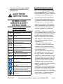
HIGH-VOLUME 12VDC
AIR COMPRESSOR
66399
Set up and Operating Instructions
Visit our website at: http://www.harborfreight.com
Read this material before using this product.
Failure to do so can result in serious injury.
Save this manual.
Copyright© 2008 by Harbor Freight Tools®. All rights reserved. No portion of this manual or any artwork
contained herein may be reproduced in any shape or form without the express written consent of
Harbor Freight Tools. Diagrams within this manual may not be drawn proportionally. Due to continuing
improvements, actual product may differ slightly from the product described herein. Tools required for
assembly and service may not be included.
For technical questions or replacement parts, please call 1-800-444-3353.
Revised Manual 10d
Save This Manual
NOTICE is used to
address practices
not related to personal injury.
Keep this manual for the safety warnings and precautions, assembly, operating, inspection, maintenance and cleaning
procedures. Write the product’s serial
number in the back of the manual near the
assembly diagram (or month and year of
purchase if product has no number). Keep
this manual and the receipt in a safe and
dry place for future reference.
Safety Alert Symbol and Signal
Words
In this manual, on the labeling,
and all other information provided with this product:
This is the safety alert
symbol. It is used to alert
you to potential personal
injury hazards. Obey all
safety messages that
follow this symbol to avoid
possible injury or death.
DANGER indicates
a hazardous
situation which, if not
avoided, will result in death or
serious injury.
CAUTION, without
the safety alert
symbol, is used to address
practices not related to
personal injury.
IMPORTANT SAFETY
INSTRUCTIONS
Instructions Pertaining
to a Risk of Fire,
Electric Shock, or
Injury to Persons
WARNING! The metal parts of the
compressor and hoses will
become hot during use.
WARNING – When using tools, basic precautions should always be followed,
including the following:
General
WARNING
indicates a
hazardous situation which, if
not avoided, could result in
death or serious injury.
a.
CAUTION, used
with the safety
alert symbol, indicates a
hazardous situation which, if
not avoided, could result in
minor or moderate injury.
SKU 66399
To reduce the risks of electric
shock, fire, and injury to persons,
read all the instructions before using the tool.
Work area
a.
Keep the work area clean and well
lighted.
b.
Do not operate the tool in explosive atmospheres, such as in the
presence of flammable liquids,
gases, or dust. The tool is able to
create sparks resulting in the ignition
of the dust or fumes.
For technical questions, please call 1-800-444-3353.
Page 2
c.
Keep bystanders, children, and
visitors away while operating the
tool. Distractions are able to result in
the loss of control of the tool.
Personal safety
a.
b.
Stay alert. Watch what you are doing and use common sense when
operating the tool. Do not use the
tool while tired or under the influence of drugs, alcohol, or medication. A moment of inattention while
operating the tool increases the risk
of injury to persons.
Avoid unintentional starting. Be
sure the switch is off before connecting to the air supply. Do not
carry the tool with your finger on the
switch or connect the tool to the air
supply with the switch on.
c.
Do not overreach. Keep proper
footing and balance at all times.
Proper footing and balance enables
better control of the tool in unexpected situations.
d.
Always wear eye protection. Wear ANSI-approved safety goggles.
e.
Always wear hearing
protection when using
the tool. Prolonged exposure to high intensity noise
is able to cause hearing loss.
Tool use and care
a.
Do not force the tool. Use the
correct tool for the application. The
correct tool will do the job better and
safer at the rate for which the tool is
designed.
SKU 66399
b.
Do not use the tool if the switch
does not turn the tool on or off.
Any tool that cannot be controlled
with the switch is dangerous and
must be repaired.
c.
Disconnect the tool from the air
source before making any adjustments, changing accessories, or
storing the tool. Turn the switch to
its off position and disconnect from
the battery.
d.
Store the tool when it is idle out of
reach of children and other untrained persons. A tool is dangerous
in the hands of untrained users.
e.
Maintain the tool with care.
f.
Check for misalignment or binding of moving parts, breakage of
parts, air leaks, frayed wires, and
any other condition that affects the
tool’s operation. If damaged, have
the tool serviced before using. Many
accidents are caused by poorly maintained tools. There is a risk of bursting if the tool is damaged.
g.
Use only accessories that are
identified by the manufacturer for
the specific tool model. Use of an
accessory not intended for use with
the specific tool model, increases the
risk of injury to persons.
Service
a.
Tool service must be performed
only by qualified repair personnel.
b.
When servicing a tool, use only
identical replacement parts. Use
only authorized parts.
For technical questions, please call 1-800-444-3353.
Page 3
c.
Use only the lubricants supplied
with the tool or specified by the
manufacturer.
Save these
instructions.
Specific Safety Instructions
1.
Do not use cigarette lighter adaptor to power this unit. If powered
with the battery of a vehicle, start and
run engine during inflation period.
2.
The warnings and precautions discussed in this manual cannot cover
all possible conditions and situations
that may occur. It must be understood by the operator that common
sense and caution are factors which
cannot be built into this product, but
must be supplied by the operator.
3.
WARNING: Some dust created by
power sanding, sawing, grinding, drilling, and other construction activities,
contains chemicals known [to the
State of California] to cause cancer,
birth defects or other reproductive
harm. Some examples of these
chemicals are:
• Lead from lead-based paints
• Crystalline silica from bricks and
cement or other masonry products
• Arsenic and chromium from chemically treated lumber
Your risk from these exposures varies, depending on how often you do
this type of work. To reduce your
exposure to these chemicals: work in
a well ventilated area, and work with
approved safety equipment, such as
those dust masks that are specially
designed to filter out microscopic
particles. (California Health & Safety
Code § 25249.5, et seq.)
WARNING: The brass components
of this product contain lead, a chemical known to the State of California
to cause birth defects (or other reproductive harm). (California Health &
Safety code § 25249.5, et seq.)
Symbols and
Specific Safety
Instructions
Symbol Definitions
Symbol
no
.../min
Property or statement
No-load speed
Revolutions or reciprocation per
minute
PSI
Pounds per square inch of pressure
ft-lb
Foot-pounds of torque
BPM
Blows per minute
CFM
Cubic Feet per Minute flow
SCFM
Cubic Feet per Minute flow at
standard conditions
NPT
National pipe thread, tapered
NPS
National pipe thread, straight
WARNING marking concerning Risk
of Eye Injury. Wear ANSI-approved
eye protection.
WARNING marking concerning Risk
of Hearing Loss. Wear hearing
protection.
WARNING marking concerning Risk
of Respiratory Injury. Wear NIOSHapproved dust mask/respirator.
WARNING marking concerning Risk
of Explosion.
SKU 66399
For technical questions, please call 1-800-444-3353.
Page 4
4.
5.
Only use with accessories rated to
handle the forces exerted by this tool
during operation. Other accessories
not designed for the forces generated may break and forcefully launch
pieces.
Attach all accessories properly to the
tool before connecting the air supply. A loose accessory may detach or
break during operation.
Vibration Precautions
This tool vibrates during use. Repeated or long-term exposure to vibration may cause temporary or permanent
physical injury, particularly to the hands,
arms and shoulders. To reduce the risk of
vibration-related injury:
Anyone using vibrating tools regularly or for an extended period should
first be examined by a doctor and
then have regular medical checkups to ensure medical problems are
not being caused or worsened from
use. Pregnant women or people
who have impaired blood circulation
to the hand, past hand injuries, nervous system disorders, diabetes, or
Raynaud’s Disease should not use
this tool. If you feel any symptoms
related to vibration (such as tingling,
numbness, and white or blue fingers),
seek medical advice as soon as possible.
WARNING! The metal parts of
the compressor and hoses
will become hot during use.
Save these
instructions.
SKU 66399
Functional Description
Specifications
Maximum Air Pressure
115 PSI
Fills Car Tire in Approx.
3 Minutes
1.3 SCFM @ 40 PSI
0.9 SCFM @ 90 PSI
Speed
Air Flow
Rated Air Pressure
0-115
Maximum Power
12VDC, 30 AMPS
Permanently Lubricated
Do not add oil or any
other lubricant
Initial Tool Set Up/
Assembly
Read the entire Important
Safety Information
section at the beginning of this
manual including all text under
subheadings therein before set
up or use of this product.
Note: For additional information regarding
the parts listed in the following pages,
refer to the Assembly Diagram near
the end of this manual.
Unpacking
When unpacking, make sure that
the item is intact and undamaged. If any
parts are missing or broken, please call
Harbor Freight Tools at the number shown
throughout the manual as soon as possible.
• This air tool may be shipped with a
protective plug covering the air inlet.
Remove this plug before set up.
Note: Air flow, and therefore tool performance, can be hindered by undersized air supply components.
For technical questions, please call 1-800-444-3353.
Page 5
1.
The air hose must be long enough
to reach the work area with enough
extra length to allow free movement
while working.
2.
Turn the tool’s On/Off switch to the
“OFF” position; refer to Operation
section for description of controls.
3.
Inspect the air connections for leaks.
Repair any leaks found.
2.
Route the air hose along a safe route
to reach the work area without creating a tripping hazard or exposing the
air hose to possible damage. The air
hose must be long enough to reach
the work area with enough extra
length to allow free movement while
working.
General Assembly and Operating
Instructions
Operating Instructions
1.
Set tool on a dry, flat, level surface.
Read the entire Important
Safety Information
section at the beginning of this
manual including all text under
subheadings therein before set
up or use of this product.
2.
To prevent accidents, turn the On/Off
Switch (25) to the “OFF” position.
3.
Attach the quick coupler of coiled Air
Hose (59) to male connector at the
end of Rubber Hose (53).
Inspect tool before use, looking
for damaged, loose, and
missing parts. If any problems
are found, do not use tool until
repaired.
4.
NOTE: Be sure to pull back on collar
of Air Hose’s coupler. Then firmly
insert connector into coupler. (See
Figure 1.) Release collar, which will
snap connector in place. Pull lightly
on both hoses to ensure proper
locking in the coupler.
Tool Set Up
To prevent
serious injury:
Do not adjust or tamper with
any control or component in a
way not specifically explained
within this manual. Improper
adjustment can result in tool
failure or other serious
hazards.
Air House (59)
Coupler Collar
Male
Connector
Fig. 1
Work Piece and Work Area Set Up 5. Attach the clamps on the Power Cord
1.
Designate a work area that is clean
and well-lit. The work area must not
allow access by children or pets to
prevent distraction and injury.
(27) onto the 12V automotive battery
(not included) power source.
a.Connect RED clamp of the Compressor to the positive (+) terminal of
the battery.
REV 10a
SKU 66399
For technical questions, please call 1-800-444-3353.
Page 6
b.Connect BLACK terminal of the
Compressor to a good ground
source on the engine block.
WARNING! Do NOT connect it to
the other battery terminal.
c. Note: The power source must not
exceed 12V.
6.
WARNING! Failure to follow the following steps can lead to a blown
fuse.
7.
Be sure the valve stem is clean and
free of dirt.
8.
Flip the On/Off Switch (25) to the
“ON” position. (See Fig. 2.)
On/Off Switch (25)
Fig. 3
12. Continue inflating until the recommended pressure is reached.
13. Stop the compressor by clicking the
On/Off Switch to its “OFF” position.
14. Remove the Air Nozzle by
unthreading it from the valve stem.
NOTE: In the case of a football or
soccer ball, pull the Needle Nozzle
(63), out of the ball valve orifice.
Fuse (26)
Fig. 2
9.
Holding the Air Nozzle Grip (56),
thread the Air Nozzle (55) onto the
valve stem of the item to be inflated,
or attach an alternate Inflator Nozzle
(61,62,63).
10. NOTE: When inflating, finger-tighten
Air Nozzle only. Do not over-tighten.
11. Monitor the Pressure Gauge carefully
to avoid over-inflating the item. (See
Fig. 3, above.)
NOTE: After disconnecting the Compressor, it is advisable to verify tire
pressure with a tire pressure gauge
(not included).
NOTE: Remember to replace the
valve cap, where applicable.
15. If the tire pressure is low, repeat the
steps beginning with Step 7.
16. Remove the clamps from the power
source.
WARNING! The metal parts of the
compressor and hoses will
become hot during use.
REV 09f, 09h; 10a; 10d
SKU 66399
For technical questions, please call 1-800-444-3353.
Page 7
To prevent serious
injury from tool
failure: Do not use
damaged equipment. If
abnormal noise, vibration,
or leaking air occurs, have
the problem corrected before
further use.
Cleaning, Maintenance and
Lubrication
Fig. 3
17. Allow this compressor to cool, then
wipe down and replace into the storage bag supplied with this unit. (See
Fig. 3.) Note: There is also a small
storage bag for inflator nozzles that is
attached to the Rubber Hose.
18. Store in a dry location.
User-Maintenance
Instructions
Procedures not specifically
explained in this manual
must be performed only by a
qualified technician.
To prevent
serious injury
from accidental
operation: Turn off the tool,
detach the Power supply
clamps, safely discharge any
residual air pressure in the
tool, and release the throttle
and/or turn the switch to its
off position before performing
any inspection, maintenance,
or cleaning procedures.
Note: These procedures are in addition to
the regular checks and maintenance
explained as part of the regular operation of the Air Compressor.
1.
Wipe down the compressor with a
clean dry cloth.
2.
Check the hoses to be sure there are
no cracks or worn areas.
3.
Rotate Filter counterclockwise and
remove from the compressor. Gently
pry the cover from the threaded end.
Remove the filter, wash in warm water and liquid soap (no harsh powder
soap), rinse thoroughly, and let dry
4.
Insert back into the filter holder. Align
the three indexing ribs on filter housing with the three recessed grooves
in the filter cover and push the cover,
snapping it onto the housing. Thread
the assembly back into the front cover, being careful not to cross thread it.
5.
Lubricate the Shaft (30) and Piston
Ring (31) after using 20 times.
a.Remove four Screws (4) holding the
Front Cover (5) in place and slide
the Front Cover off. (See Assembly
Diagram.)
b.Put a drop or two of machine oil on
the Shaft (30) and Piston Ring (31).
REV 10a
SKU 66399
For technical questions, please call 1-800-444-3353.
Page 8
Note: Turn the Compressor upside
down to allow the oil to penetrate
onto the piston rings.
c. Slide the Front Cover back on and
secure in place with the four screws.
6.
If the Fuse (26) needs to be replaced,
snap off Fuse cover and then remove
and replace Fuse.
7.
Slide out Fuse holder, replace old
Fuse with new Fuse included in the
inflator nozzle bag, and slide Fuse
holder back into slot. Fasten back
into place with screws.
8.
When the tool needs servicing, it
should only be serviced by a qualified
technician.
Troubleshooting
Problem
Possible Causes
Decreased output. 1. Not enough air pressure and/
or air flow.
2. Blocked air inlet Filter (3).
3. Air leaking from loose housing
or connections.
4. Mechanism contaminated.
Severe air
1. Cross-threaded housing
leakage.
components.
(Slight air leakage
is normal,
2. Loose housing.
especially on older
tools.)
3. Damaged valve or housing.
4. Dirty, worn or damaged valve.
1. Poor clamp connection.
2. Power Switch in Off (O)
position.
3. Run-down battery.
4. Blown Fuse.
No output
Likely Solutions
1. Check for loose connections.
2. Clean air inlet screen of buildup.
3. Make sure housing and connections are
properly assembled and tight.
4. Have qualified technician clean and where
possible, lubricate mechanism.
1. Check for incorrect alignment and uneven
gaps. If cross-threaded, disassemble and
replace damaged parts before use.
2. Tighten housing assembly. If housing cannot
be tightened properly, internal parts may be
misaligned.
3. Replace damaged components.
4. Clean or replace valve assembly.
1. Clean clamps and reconnect properly.
2. Turn Power Switch to On (I) position.
3. Recharge battery.
4. Replace Fuse.
Follow all safety precautions whenever diagnosing or servicing the
tool. Disconnect from inflated item before service.
REV 10d
SKU 66399
For technical questions, please call 1-800-444-3353.
Page 9
Parts List
Part
1
2
3
4
5
6
7
8
9
10
11
12
13
14
15
16
17
18
19
20
21
22
23
24
25
26
27
28
29
30
31
32
33
34
35
36
Description
Base Board
Pad
Filter
Screw 4x8
Front Cover
Screw 5x14
Ring
Offset Wheel
Front End Cover
Decorative Ring
Nut
Bearing 6201z
Armature
Bearing 608z
Motor Cover
Brush Bracket
Motor Cover Board
Temperature Controler
Spring Washer
Screw 5x150
Nut
Decorative Ring
Rear Cover
Screw 5x14
Switch
Fuse Holder
Power Cord
Clamp
Bearing 6201z
Shaft
Piston Ring
Pressing Ring
Air Inlet Valve Slice
Rivet
Cylinder Liner
Seal Ring
Parts List
Qty.
1
4
1
4
1
4
1
1
1
1
4
1
1
1
1
1
1
1
2
2
4
1
1
4
1
1
1
2
1
1
1
1
1
1
1
1
Part
37
38
39
40
41
42
43
44
45
46
47
48
49
50
51
52
53
54
55
56
57
58
59
60
61
62
63
Description
Air Storage Cap
Seal Ring
Air Exhaust
Rivet
Seal Ring
Radiation Cover
Cylinder Cover 1
Spring Washer
Screw 5x50
Cylinder Cover 2
Screw 4x12
Triangle Bracket 1
Air Hose
Handle
Triangle Bracket 2
Air Hose Connector
Rubber Hose
Air Hose Connector
Air Nozzle
Air Nozzle Gripe
Rubber Hose
Pressure Gauge
Air Hose
Quick Connector
Inflator Nozzle 1
Inflator Nozzle 2
Needle Nozzle
Qty.
1
2
2
2
1
1
1
4
4
1
1
1
1
1
1
1
1
1
1
1
1
1
1
1
1
1
1
Accessory LIST
Part
Description
Function
61
Inflator Nozzle 1
Medium size fill orifice
62
Inflator Nozzle 2
Small size fill orifice
63
Needle Nozzle
Inflate balls
Fuse, Blade Type
Overload Protection
26A
REV 10a
SKU 66399
For technical questions, please call 1-800-444-3353.
Page 10
ASSEMBLY DIAGRAM
SKU 66399
For technical questions, please call 1-800-444-3353.
Page 11
Limited 1 Year warranty
Harbor Freight Tools Co. makes every effort to assure that its products meet high
quality and durability standards, and warrants to the original purchaser that this product
is free from defects in materials and workmanship for the period of one year from the
date of purchase (90 days if used by a professional contractor or if used as rental equipment). This warranty does not apply to damage due directly or indirectly, to misuse,
abuse, negligence or accidents, repairs or alterations outside our facilities, normal wear
and tear, or to lack of maintenance. We shall in no event be liable for death, injuries
to persons or property, or for incidental, contingent, special or consequential damages
arising from the use of our product. Some states do not allow the exclusion or limitation
of incidental or consequential damages, so the above limitation of exclusion may not apply to you. This warranty is expressly in lieu of all other warranties,
express or implied, including the warranties of merchantability
and fitness.
To take advantage of this warranty, the product or part must be returned to us with
transportation charges prepaid. Proof of purchase date and an explanation of the complaint must accompany the merchandise. If our inspection verifies the defect, we will either repair or replace the product at our election or we may elect to refund the purchase
price if we cannot readily and quickly provide you with a replacement. We will return repaired products at our expense, but if we determine there is no defect, or that the defect
resulted from causes not within the scope of our warranty, then you must bear the cost
of returning the product.
This warranty gives you specific legal rights and you may also have other rights
which vary from state to state.
3491 Mission Oaks Blvd. • PO Box 6009 • Camarillo, CA 93011 • (800) 444-3353
Record Product’s Serial Number Here:
Note: If product has no serial number, record month and year of purchase instead.
Note: Some parts are listed and shown for illustration purposes only, and are not available individually as replacement parts.
PLEASE READ THE FOLLOWING CAREFULLY
The manufacturer and/or distributor has provided the parts list and assembly diagram in
this manual as a reference tool only. Neither the manufacturer or distributor makes any
representation or warranty of any kind to the buyer that he or she is qualified to make any repairs
to the product, or that he or she is qualified to replace any parts of the product. In fact, the
manufacturer and/or distributor expressly states that all repairs and parts replacements should
be undertaken by certified and licensed technicians, and not by the buyer. The buyer assumes all
risk and liability arising out of his or her repairs to the original product or replacement parts
thereto, or arising out of his or her installation of replacement parts thereto.
SKU 66399
For technical questions, please call 1-800-444-3353.
Page 12