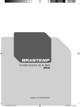
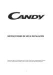
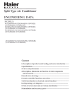
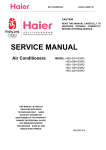
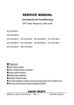
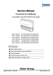
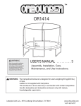
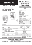
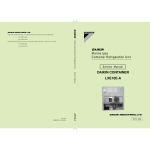
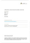
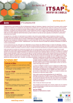
1
Domestic Air Conditioner SERVICE MANUAL Models HSU-22H03/R2(DB) l Features l l l l Comfortable:wide -angle airflow health air purifying quiet operation energy efficient Serial Number: Version:00.00 1 Edition: 2005-11-16 Domestic Air Conditioner Model: HSU-22H03/R2(DB) Content 1. 2. 3. 4. Description of product model coding and series introduction--3 Specifications -------------------------------------------------------------6 Curves of performance of compressor-------------------------------8 Description, net dimensions and functions of main component s and accessories------------------------------------------------------------10 5. Knock-down drawings and part lists ---------------------------------13 6. Brief introduction to electrical control functions ------------------18 7. Wiring diagram ----------------------------------------------------------30 8. Circuit diagram ------------------------------------------------------------33 9. Abnormity diagnosis ------------------------------------------------------- 36 10. Trouble shooting ------------------------------------------------------------38 11. Refrigerating cycle diagram ------------------------------------------40 12. Noise level test chart and air velocity distribution -------------------------- 42 13. Installation manual -----------------------------------------------------45 2 Domestic Air Conditioner Model: HSU-22H03/R2(DB) DESCRIPTION OF PRODUCT MODEL CODING & SERIES INTRODUCTION 3 Domestic Air Conditioner Model: HSU-22H03/R2(DB) Introductory Remarks Description of coding rules of unit model Coding rules and descriptions are as follows: 1 2 3 4 5 6 7 8 9 10 11 Inverter type:(DB),(B) Refrigerant type:R1(R407C),R2(R410A) Applicable voltage:3(220~230V),4(240V) Applicable frequency:0(50HZ),1(60HZ) Developing sequence :A,B,C,D... L/C-cooling only Function code R/H-heat pump E-electric aided heating Nominal cooling capacity (BTU/h)with the first two numbers based on thousand unit The structure code of indoor & outdoor unit: S(wall-mounted),W(window type),P (cabinet type) H-Abbreviation of Haier Examples: HSU-22H03/R2(DB) represents wall-mounted split type heat pump DC inverter air conditioner . and "R2" means The cooling capacity is 22000BTU/h and the power supply is 230V/50Hz the refrigerant is R410A. 4 Domestic Air Conditioner Model:HSU-22H03/R2(DB) Description of product model coding and series introduction Standard Situation/Conditions No. Operating condition indoor air status DB C WBOC outdoor air status DB C WBOC 1 Norminal cooling 27OC 19OC 35OC 24OC 2 Norminal heating 20OC Not control 7OC 6OC 3 Norminal electrical heating --- --- O --- --- O C.Series brief introduction 1.comfortable:wide-angle airflow The vertical dual-flap and horizontal wide-angle louvers ensure the cool (warm) air reaches every corner of the room. 2.Health air purifying An air purifying filter with deodorizing and disinfecting functions keeps the air clean and users healthy. 3.Quiet operation Fan With Random-pitched Blades. Random-pitched blades help reduce operating noise while maintaining a high airflow rate. 4.Energy efficient The design of inner-grooved copper tube greatly increases the refrigerant contact area and the efficiency of cooling/heating functions. 5.Convenience Auto restart and washable panel: The grille can be removed and washed easily when necessary. With Auto restart function the unit will automatically return to the operating settings in use before the power failure when power is restored. 6.Wide variety of functions 24-Hour Timer: 24-hour timer allows users to select the exact time they would like the air conditioner to turn on and to turn off. Timers on previous models operation are based on the number of hours of desired operation. 7.Night-set models When the air conditioner is operating on the timer-off circuit.The preset room temperature gradually rises (going down in heating) before the unit stops as shown below. Users can sleep comfortably without sudden change in temperature. 8.Program”dry” This function automatically reduces the level of humidity while maintaining the preset indoor temperature. 5 Domestic Air Conditioner Specifications 6 Model:HSU-22H03/R2(DB) Domestic Air Conditioner Model: Domestic Air Conditione HSU-22H03/R2(DB) Model: HSU-22H03/R2(DB) Specifications Model: HSU-22H03/R2(DB) Cooling capacity(W) 6000(720-6300)W Cooling coefficient (W/W) Cooling power input (W) Moiture removal (m/h) 3.03 Heating coefficient(W/W) 1980(310-2450)W 3 Heating capacity(W) -3 2.3 X10 Heating power input(W) Frequency range(Hz) Operating voltage range V( ) 230 Refrigerant type Operating temp.range OC( ) -7-43 Variation of temp.adjust OC( ) +1 Climate type: T1 Class of electric shock 44/39/37 44/39/37 Net dimensions mm (indoor unit) Packaging dimensions mm (indoor unit) Net/gross weight (kg) (indoor unit) Max. mounting height Refrigerant charge(g) (R410A) Compressor model Compressor oil charge (cc) Maxi. length of connecting pipe (m) Cap. tube type muffle model: cool heat (outdoor unit) two-way Cut-off vavle(inch) three-way Max. operating pressure at 2060W(430-2600)W 50 outdoor unit Outdoor unit noise (cooling) 60O Cross flow fan Axial flow fan I 56 Outdoor unit noise (heating) Net dimensions mm (outdoor unit) Packaging dimensions mm (outdoor unit) Net/gross weight (kg) (outdoor unit) 56 810×288×680 915×325×699 45/53 indoor unit 8 outdoor unit Current entering side (indoor/outdoor) 4 Piling layers indoor Once/2 weeks Max. refrigerant charge (g) 15 C-6RVN93H0N Compressor manufacturer HUARUN 350(poe) Compressor protector type drain hose length(mm) diametre(mm) Internal 2000 16 15 1/4 Type of tube of evaporator and condenser Size of tube of evaporator and condenser(mm) Appearance features of indoor unit Appearance features of outdoor 1/2 unit TP2Y Fan speed(r/min) warm side(Mpa) 11/14 1900 Frequency of filter cleaning (indoor unit) 990×260×315 5 difference(m) Fan speed(H/M/L)(r/min) 938×182×265 3.01 R410A Air sending angle indoor unit Fan type Indoor unit noise (cooling) Indoor unit noise (heating) 6200W(1080-7750)W 1350/1250/1150 1350/1250/1150 760 Max. operating pressure at 4.15 cool side(Mpa) 7 Internal thread Ø 6.35 / Ø 12.7 plastic metal 4.15 Domestic Air Conditioner Model: HSU-22H03/R2(DB) Curves of performance of compressor 8 Domestic Air Conditioner Model:HSU-22H03/R2(DB) Curves of cooling capacity and heating capacity as a function of outdoor temperature(-7OC~43OC) 150 140 130 120 15 110 20 100 25 90 15 20 25 9 Domestic Air Conditioner Model: HSU-22H03/R2(DB) Description,dimensions and functions of main components and accessories 10 Domestic Air Conditioner Model: HSU-22HV03/R2(DB) Test running switch(manual) Used only for test running in cooling when room temp. is below 16oC. Don't use it in normal operation. Inlet grille Emergency switch(manual) Used when remote controller is lost or defective. Unit will run temporarily. Remote signal receiver Air filter A beeping sound is generated when a signal from remote controller is received. Vertical flap Power indicator Timer mode indicator Operation mode indicator Use remote controller to adjust up and down air flow. (Don't adjust it manually.) Lights up when unit starts. Lights up when Timer operation is selected. Lights up during compressor running. For model: HSU-22H03/R2(DB) 11 Domestic Air Conditioner Model: HSU -22H03/R2(DB) NET DIMENSIONS: Indoor unit for HSU-22H03/R2(DB) 938 265 182 690 NET DIMENSIONS: outdoor unit for HSU-22H03/R2(DB) 113.5 583 810 12 Domestic Air Conditioner Model:HSU-22H03/R2(DB) Knock-down drawings and part lists 13 Domestic Air Conditioner 14 Model: HSU-22H03/R2(DB) Domestic Air Conditioner No. in Spare parts explode number d view Spare parts description in english HSU-22H03/R2(DB) Failure rate Model Qty. 1 1 1 1 1 1 1 1 1 1 1 1 1 1 1 1 1 1 1 1 1 0.0 1 1 1 1 1 1 0.1 1 0010807073 Indoor elecrtic box HSU-22H03/R2(DB) 2 0010403617 PCB HSU-22H03/R2(DB) 3 001A0600287 Riever HSU-22H03/R2(DB) 4 001A1431717 Motor cover HSU-22H03/R2(DB) 5 001A3900059 Coil cover HSU-22H03/R2(DB) 6 0010400633 transformer HSU-22H03/R2(DB) 7 001A4000161 Terminal block HSU-22H03/R2(DB) 8 ---- Wires HSU-22H03/R2(DB) 9 001A1231134 Front panel HSU-22H03/R2(DB) 10 001A1231135 Front grille HSU-22H03/R2(DB) 11 001A0100276 Frame assy. HSU-22H03/R2(DB) 12 001A1431494 Service cover HSU-22H03/R2(DB) 13 001A3000088 Motor cover HSU-22H03/R2(DB) 14 0010202227 Fan HSU-22H03/R2(DB) 15 001A0300005 Bearing HSU-22H03/R2(DB) 16 001A0900104 Drain horse HSU-22H03/R2(DB) 17 001A3000008 Motor cover HSU-22H03/R2(DB) 18 001A1231139 Flap HSU-22H03/R2(DB) 19 001A0900011 Dain horse HSU-22H03/R2(DB) 20 0010707193 Heat exchanger HSU-22H03/R2(DB) 21 001A2400080 Air filter HSU-22H03/R2(DB) 22 0010101275 Mounting plate HSU-22H03/R2(DB) 23 001A1431368 Piping support HSU-22H03/R2(DB) 24 001A1431038 Piping clamp HSU-22H03/R2(DB) 25 0010403894 Remote controller HSU-22H03/R2(DB) 26 001A1434039 Drain horse HSU-22H03/R2(DB) The proportion of the spare remark part stock X 0.1 0.2 * 0.2 * 0.0 X 0.1 0.2 * 0.1 0.2 * 0.1 0.1 0.1 0.1 0.2 * 0.2 * 0.2 * 0.1 0.1 0.1 0.1 0.1 0.1 0.2 * 0.2 * 0.1 27 001A1231140 Flap HSU-22H03/R2(DB) 0.1 1,The failer rate and the proportion of the spare-part stock are regarded as the reference of the stock for spareparts;The first time should be stocked accroded with the proportion of the spare-parts,and it should be adjusted with the actual quantity 3 months later. 2,easy-damaged;The spare-part which is often damaged and the customer must stock in the spare-parts warehouse,and should be marked with"*" 3,possible damaged:The spare-part which is not often damaged like the easy damaged one and the customer may stock in the spare-part warehouse accord with the actual case,should be marked with " ". 4,not need provided :The spare-part which is seldom damaged or the maintenance man could not maitmains.The spare parts may be air freighted by the factory if they were damaged.The customer nees not stock in the spare-part warehouse,should be marked with " x ". 5,Above should be improved accord with the reply of the market half a year per time. 6.The spare parts price on net is FOB Qingdao term. 15 Domestic Air Conditioner Model: HSU-22H03/R2(DB) 17 22 21 19 20 24 1 2 3 4 26 5 25 6 8 7 9 12 23 13 14 11 18 10 15 16 KNOCK-DOWM DRAWINGS FOR OUTDOOR UNIT 16 Domestic Air Conditioner Model: HSU-22H03/R2(DB) Edition:2005/11/16 No. in exploded view Spare parts number Spare parts description in english Model Qty Failure rate(%) The proportion of the spare part stock Remark 1 001A1303126A Front grille HSU-22H03/R2(DB) 1 outdoor 2 001A1101038 Front panel HSU-22H03/R2(DB) 1 outdoor 3 001A2331024 Axial fan HSU-22H03/R2(DB) 1 outdoor 4 0010403895 Motor HSU-22H03/R2(DB) 1 outdoor 5 001A1301133 Bracket for fan motor HSU-22H03/R2(DB) 1 outdoor 6 0010705512 Condenser HSU-22H03/R2(DB) 1 outdoor 7 001A0100356 Side panel(left) HSU-22H03/R2(DB) 1 outdoor 8 001A1436182 Handle HSU-22H03/R2(DB) 1 outdoor 9 001A0100124 Panel(top) HSU-22H03/R2(DB) 1 outdoor 10 001A0100125 Service cover HSU-22H03/R2(DB) 1 outdoor 11 001A0100997 Side panel(fight) HSU-22H03/R2(DB) 1 outdoor 12 0010806797 Electric box assy. HSU-22H03/R2(DB) 1 outdoor 13 0010703520 4-wan valve coil HSU-22H03/R2(DB) 1 outdoor 14 --- Tube assy HSU-22H03/R2(DB) 1 outdoor 14-1 0010706999 Discharging tube assy. HSU-22H03/R2(DB) 1 outdoor 14-2 0010707000 Suction tube HSU-22H03/R2(DB) 1 outdoor 14-3 0010707001 Suction tube assy. HSU-22H03/R2(DB) 1 outdoor 14-4 0010707002 Discharging tube assy. HSU-22H03/R2(DB) 1 outdoor 15 0010706999 Capillary assy. HSU-22H03/R2(DB) 1 outdoor 16 0010705987 Service valve HSU-22H03/R2(DB) 1 outdoor 17 0010705989 Service valve HSU-22H03/R2(DB) 1 outdoor 18 --- Nut HSU-22H03/R2(DB) 1 outdoor 19 --- Service cover HSU-22H03/R2(DB) 1 outdoor 20 --- Nut HSU-22H03/R2(DB) 1 outdoor 21 0010707200 Compressor HSU-22H03/R2(DB) 1 outdoor 22 --- Rubber cushion HSU-22H03/R2(DB) 1 outdoor 23 --- Wire group HSU-22H03/R2(DB) 1 outdoor 24 001A17621543 Pad HSU-22H03/R2(DB) 1 outdoor 25 0010806754 Bottom plate assy. HSU-22H03/R2(DB) 1 outdoor 26 0010800009 Separating plate HSU-22H03/R2(DB) 1 outdoor 1,The failer rate and the proportion of the spare-part stock are regarded as the reference of the stock for spare-parts;The first time should be stocked accroded with the proportion of the spare-parts,and it should be adjusted with the actual quantity 3 m 2,easy-damaged;The spare-part which is often damaged and the customer must stock in the spare-parts warehouse,and should be marked with"*" 3,possible damaged:The spare-part which is not often damaged like the easy damaged one and the customer may stock in the spare-part warehouse accord with the actual case,should be marked with " ". 4,not need provided :The spare-part which is seldom damaged or the maintenance man could not maitmains.The spare parts may be air freighted by the factory if they were damaged.The customer nees not stock in the spare-part warehouse,should be marked wit 5,Above should be improved accord with the reply of the market half a year per time. 6.The spare parts price on net is FOB Qingdao term. 17 Domestic Air Conditioner Model: HSU-22H03/R2(DB) Brief introduction to electrical control functions 18 Domestic Air Conditioner Model: HSU-22H03/R2(DB) One. Basic Control 1. Function Display Lights up when unit starts.Lights up when Timer operation is selectedn; 2. Temperature Adjustment Function In temperature adjustment function, operation frequency of outdoor unit is determined based on indoor temperature and set temperature. During wind speed adjustment, indoor fan PI(D)is controlled as per the needs of temperature adjustment. 3. Compressor Off Compressor is off when indoor temperature is 1o above set temperature (heating mode) / 1o below set temperature (cooling mode). 4. Compressor On Compressor is on when indoor temperature is -0.67o below set temperature (heating mode)/ 0.67o above set temperature (cooling mode). 5. Remote Control Operation In remote control, if temperature changes, PI operation will start in 2s. If change of set temperature is towards compressor off, compressor will shut down when it falls into compressor-off temperature range. 6. Indoor Fan Rotate Speed Mode Heating Cooling Wind Speed Weak 650 Low 950 Middle 1050 High 1150 Super High -- Weak 650 Low 950 Middle 1050 High 1150 Super High Ventilation Rated Rotate Speed(rpm) -- Low 950 Middle 1050 High 1150 Cooling Heating 1350 1350 19 Domestic Air Conditioner Model: HSU-22H03/R2(DB) Two. Operation Mode: 1. Half-automatic Operation Mode Half-automatic function is based on original automatic function. a. Cooling & Heating Model Unit When system is on and operation mode switches to automatic, the system will determine operation mode based on the difference of current set temperature and room temperature and will start operation as per mode determined. In the following selective conditions, Tr represents room temperature and Ts represents set temperature. Upon initial entry into automatic mode, operation mode is selected as per the following conditions: Tr≥Ts-3℃ Cooling mode is selected Tr<Ts-3℃ Heating mode is selected When entering automatic mode, the system can switch between cooling and heating mode corresponding to change of room temperature: If the unit is currently in cooling mode, compressor will shut down when temperature falls into compressor off temperature range. 15 minutes after compressor is off, compressor will perform temperature check, at which time if Tr<Ts-3℃ the system will enter heating mode otherwise it will remain in cooling mode. If the unit is currently in heating mode, compressor will shut down when temperature rises into compressor off temperature range. 15 minutes after compressor is off, compressor will perform temperature check, at which time if Tr>Ts+3℃ the system will enter cooling mode otherwise it will remain in heating mode. 2.Cooling Mode: *Temperature Control Range:16℃---30℃ *Temperature Difference: ±1℃ *In the first 2 minutes after compressor starts, it is not under the control of temperature sensor. *Control Feature: When Tr(air intake)>Ts(set)℃,compressor external air fan is on, indoor fan operates at set speed. When Tr(air intake)<Ts(set),compressor external air fan is off, indoor fan operates at set speed. When Tr= Ts, the system will remain its original state. *Wind Speed Control:(temperature difference 1℃) Automatic: When Tr>=Ts+3℃, high wind; When Ts+1℃≤Tr Ts+3℃, middle wind; When Tr<Ts+1℃, low wind Temperature sensor is off and air fan is in low wind speed Manual: High, middle, low and automatic wind may be set as needed when unit is on. (The unit will act 5s after receiving remote control signal.) *Compressor Control: Compressor is not under the control of temperature sensor in the first 2 minutes after it starts and compressor can only restart at least 3 minutes after it shuts down. There is no 3-minute protection at initial energization. (There are power cutoff compensation and 3-minute protection features). 20 Domestic Air Conditioner Model: HSU-22H03/R2(DB) * In case change of set temperature by remote control meets the condition of unit shut down or unit is powered off manually, the operation is not restricted by the 2-minute non-response feature and the unit will shut down immediately. 3.Dehumidification Mode: *Temperature Control Range:16---30℃ *Temperature Difference :±1℃ *Control Feature: When Tr >Ts +2℃, compressor operates at normal state and indoor fan operates at set speed. z When Tr is between Ts+2℃ and Ts, compressor operates at low frequency and fan is in weak wind mode. zF Tr <Ts, compressor and external fan will shut down, and indoor fan will stop for 3 minutes and then enters weak wind mode. zF There is ±1℃ set temperature difference in each mode. *Wind Speed Control: Automatic When Tr >=Ts +5℃, high wind; When Ts +3℃≤Tr <Ts+5℃, middle wind; When Ts+2℃≤Tr <Ts+3℃, low wind; When Ts≤Tr<Ts+2℃, intermittent operation at weak wind; Tr <Ts, fan will standby for 3 minutes and indoor fan is off (except oxygen or fresh air feature is set) Tr<Ts, fan will standby for 3 minutes and enter weak wind mode. *Compressor Control: Compressor is not under the control of temperature sensor in the first 2 minutes after compressor starts and compressor can only restart at least 3 minutes after it shuts down. There is no 3-minute protection at initial energization. (There is 3-minute protection if the unit has power outage compensation feature. * In case change of set temperature by remote control meets the condition of unit shut down or unit is powered off manually, the operation is not restricted by the 2-minute non-response feature and will shut down immediately. 4.Heating Mode: *Temperature Control Range:16---30℃ *Temperature Difference :±1℃ *Control Feature: When for the first time Tr≤Ts, compressor, four-way valve and external fan are turned on and indoor fan operates at anti cold wind mode. +4o temperature compensation will automatically be added on entering heating mode. When Tr >Ts+5, external fan of compressor is off and indoor fan will operate in residual heat blow mode. When Tr<Ts+5, compressor, four-way valve and external fan are turned on and indoor fan operates at anti cold wind mode. *Indoor Fan Control: Manual Control: High, middle, low and automatic wind may be set as needed Automatic Control: when Tr >Ts, high wind, when Ts>=Tr> Ts+2℃, middle wind, when Tr> Ts+2℃, low wind. There is no delay when wind speed rise from low to high speed while there is a 3-minute delay when wind speed fall from high to low speed (Fan will operates in high wind for 3 minutes). The unit can restart at least 3 minutes after shut down. There is no 3-minute protection at initial energization. (There is 3-minute protection if the unit has power outage compensation feature. *Compressor Control: Compressor Control: Compressor is not under the control of temperature sensor in the first 2 minutes after compressor starts and compressor can only restart at least 3 minutes after it shuts down. There is no 3-minute protection at initial energization. (There is 3-minute protection if the unit has power outage compensation 21 Domestic Air Conditioner Model: HSU-22H03/R2(DB) feature. *In case change of set temperature by remote control meets the condition of unit shut down or unit is powered off manually, the operation is not restricted by the 2-minute non-response feature and will shut down immediately. *Anti Current Surge: External fan starts 2s after compressor is on. *Timed Power On & Off Feature *Sleep Control Feature *Four-way Valve Control: Four-way valve is on 10s prior to compressor startup and off 2 minutes and 30 seconds after compressor shutdown. *Anti Cold Wind Operation: (1)Compressor operation or compressor operation after defrosting. When indoor heat exchanger temperature is below 23℃, indoor fan is off; when indoor heat exchanger temperature is above 23℃, fan operates in weak wind mode. (2)If, after 4 minutes, coil temperature can not exceed 38℃, fan will operate at set speed. (3)If coil temperature exceed 38℃, fan will operate at set speed. (4)If coil temperature falls below 38℃ when compressor is running, fan will still operate at set speed. *Residual Heat Blow: Temperature sensor is off: If coil temperature is above 23℃, fan will enter weak wind mode, if coil temperature below 23℃, indoor fan will stop. Remote Control Shut Down: Deflector will close after set wind blows for 1 minute. *Automatic Temperature Compensation in Heating Mode 1 Condition: Compressor shutdown time is less than 5 minutes 2. Operation Rule: 1)Ts =Trc+5℃+(Trc -Tt [The instant when compressor starts up] ) 2)Trc-Tt[The instant when compressor starts up] ≤2℃ Note: The above two conditions are not applicable to initial start-up. 3 ) Press “–”temperature key on remote control, and resume Ts =Trc+5℃ operation; Press “+”temperature key on remote control, it will operate based on automatic compensation set value. 4)If Trc -Tt[before compressor is on] ≤0℃, it will operate as per Ts=Trc+5. 3. If ventilation door is in healthy up-flow position, set temperature in heating mode will be increased by 2℃on its original basis. 5.Defrosting Mode Air fan will engage in anti cold wind operation based on the data sent by heat exchanger temperature sensor. Sensor fault will not be checked within the first 2 minutes after exiting defrosting mode. 6. Negative Ion Health Feature Control When receiving remote control signal, if fan is operating, negative ion generator will start working to discharge negative ion. If air fan is off, negative ion generator will be off. When negative ion generator is off, if health feature is set, then negative ion generator will turn on when fan start operation again. 7. Timed Operation 22 Domestic Air Conditioner Model: HSU-22H03/R2(DB) Time count starts based on time difference between timing clock and current clock. Time off may be set and operation will stop when unit receives time off signal. Timed on may be set and operation will start when unit receives time on signal. Timed on/off may be set, which will be performed as per set sequence. 8. Sleep Operation 8-1.In cooling/dehumidification mode, set temperature will rise by 1℃ after one hour of operation and it will rise another 1℃ after another hour. The unit will shut down after operation for another 6 hours. 8-2.In heating mode, set temperature will fall 2℃ after one hour and it will fall another 2℃ for another hour and it will rise 1℃ after another 3 hours and the unit will shut down operation after another 3 hours. 8-3 If wind speed of indoor fan is high before setting sleep mode, then it will switch to middle wind after sleep mode is set. If wind speed of indoor fan is middle before setting, it will switch to low level after setting. If wind speed of indoor fan is low before setting, then it will remain unchanged after setting. 9.Trial Operation Wind speed is high and trial operation will end in 30 mins, and unit will shut down. In trial operation, the unit will exit trial operation mode when receives remote control signal and low load protection will not be activated. 10.EEPROM Control When outdoor unit is supplied with power, if EEPORM parameter is inconsistent with checksum, EEPROM faults. When indoor unit receives EEPROM fault signal from outdoor unit, it will display outdoor unit EEPROM fault. At this time, control and emergency operation are not accepted and the fault can only be relieved by power off. Three. Special Function 1.Power-off Compensation a Entry Condition: Press sleep key 10 times in 7s and buzzer sounds 4 times and the current status is saved into indoor unit EEPROM upon the entry. b. On entering power-off compensation operation, indoor unit operates as per the following procedures: The unit operates as per condition set by remote control and emergency setting and current status is saved into indoor unit EEPROM. c. Exit Condition: Press sleep key 10 times in 7s and buzzer sounds 2 times 2. Rated Operation ① Rated Cooling a. Entry Condition: The unit will enter rated cooling upon receipt of remote control signal. b. Indoor unit will operate as per the following procedures when entering remote control cooling mode: Air fan will enter manual high wind (or rated wind) operation, panel will display cooling and rated data signal is in communication. c. Exit Conditions: The unit will exit rated operation when receiving remote control or press-key signal and it will enter the mode set by remote control and press key. 23 Domestic Air Conditioner Model: HSU-22H03/R2(DB) ② Rated Heating a Entry Condition: The unit will enter rated heating upon receipt of remote control signal. b Indoor unit will operate as per the following procedures when entering rated heating mode: Air fan will enter manual high wind (or rated wind) operation, panel will display heating and rated data signal is in communication. c Exit Conditions: The unit will exit rated operation when receiving remote control or press-key signal and it will enter the mode set by remote control and press key. 3. Emergency Switch: When unit is in shutdown condition, press emergency switch down for less than 5s, the unit will start emergency operation. When unit is in shutdown condition, press emergency switch down for more than 5s but less than 10s, the unit will start trial operation. When shutdown, press emergency switch down for more than 10s but less than 15s, it will display the previous fault. When unit is in shutdown condition, press emergency switch down, the panel will display automatic operation. When fault occurs, press emergency switch and the unit will shut down and fault is cleared. During fault display, press emergency switch will end fault display mode. 24 Domestic Air Conditioner Model: HSU-22H03/R2(DB) One. System Major Function Sensor Code Definition: Tai= Indoor Ambient Temperature, Tao=Outdoor Ambient Temperature, Tc1=Indoor Coil, Td= Air Discharge, Te= Outdoor Coil, Ts=Air Intake 1.1: Outdoor Unit Operation Frequency and Control 1.1.1: Compressor Operation Frequency Control z Compressor Operation Frequency Range: Outdoor Temperature ~0℃ 0℃~ Heating 17RPM 110RPM 17RPM 120RPM Cooling 20RPM 110RPM 20RPM 120RPM Defrosting 88rpm 1.1.2: Compressor Startup Regardless of target frequency of indoor unit, each time when compressor is from off to on, it must maintain 60Hz and 90Hz for one minute respectively (Frequency will be immediately decreased under the condition that outdoor unit air discharge temperature overheating protection is activated or overcurrent of compressor) then the compressor will operate towards target frequency. This process does not exist in normal operation of unit. 1.1.3:Heating: z When completing compressor startup operation, it will operate as per frequency of indoor unit. z After 2 minutes, compressor operation frequency will be compensated as per relevant conditions. 1.1.4 Cooling & Dehumidification: z When completing compressor startup operation, it will operate as per frequency of indoor unit. z After 2 minutes, compressor operation frequency will be compensated as per relevant conditions. 1.1.5: Compressor Frequency Increase/Decrease Speed Rapid Frequency Increase/Decrease Speed 1 ----------1HZ/s Slow Frequency Increase/Decrease Speed 2 -----------1HZ/10s 1.2: Outdoor Fan Control 1.2.1: Wind speed control when AC fan is adopted for outdoor unit. z Whether to use AC fan or DC fan is determined by EEPROM z Residual Heat Blow: After compressor shuts down in cooling mode, fan will run for 30s at low speed before stop. z Wind Speed Adjustment Table (when compressor starts up for 3 minutes) Ambient Temperature ~10 10~25 25~ Cooling & Dehumidification Low Wind Low Wind High Wind Heating High Wind Low Wind Low Wind z Wind Speed Adjustment Table (based on ambient temperature and compressor frequency after compressor runs for 3 minutes) Cooling Compressor Frequency F<25Hz 25Hz<=F<45Hz 45Hz<=F Above 28℃ Low Wind High Wind High Wind Tao Below 28℃ Low Wind Low Wind High Wind Heating Compressor Frequency F<25Hz 25 25Hz≤F<45Hz 45Hz≤f Domestic Air Conditioner Tao Above 15℃ Below 15℃ Low Wind Low Wind Model: HSU-22H03/R2(DB) Low Wind High Wind High Wind High Wind 1.3: Four-way Valve Control z Defrosting Four-way Valve Control,(please see defrosting process for details) Time sequence of the defrosting operation is as follows: Compressor Outdoors fan motor Four-way valve 60×9Max Four-way Valve Work Status in Other Modes: In heating mode, four-way valve is on. If compressor is off or is switched to non-heating mode, four-way valve ensures that it is off at least 2 minutes after compressor shuts down. 1.5 Outdoor Defrosting Control A. Defrosting Mode Entry Conditions The unit will enter defrosting mode when compressor starts up and operates for 10 minutes continuously in heating mode and accumulated running time exceeds 45 minutes (Upon completion of defrosting or when switched to cooling mode, compressor accumulated operation time will be cleared) and when 2 minutes’ continuous checking by defrosting sensor TE (check frosting condition of outdoor unit heat exchanger) and outdoor ambient temperature sensor TA meets the following conditions: TE≤C×TA-α Among which :C:TA<0℃,C=0.8 TA≥0℃,C=0.6 For area prone to frost, the value is set at 6 when unit leaves the factory. Defrosting entry temperature control -15℃≤C×TA-α≤-5℃ B. Defrosting Time Interval z When data calculated by C×TA-αfalls into the range of -15℃≤C×TA-α, time interval between two defrosting cycles is 45 minutes. z When data calculated by C×TA-αfalls into the range of C×TA-α<-15℃, time interval between two defrosting cycles is 65 minutes. z C. Defrosting Operation z When defrosting begins, compressor will stop for one minute, external fan is running and 50s later, four-way valve will be off. z When compressor starts, external fan will be off, compressor will run at 60HZ for 60s then move on to target frequency of 88HZ. z During defrosting, compressor current and air discharge overheat protection features are effective. During defrosting, if compressor shuts down due to activation of protection feature or due to malfunction, it will resume after 3 minutes. In the unit is still within defrosting cycle, it will resume defrosting and startup of compressor will be based on the rule for defrosting startup. (The unit will exit defrosting mode and handle fault in the event of 3 consecutive restart failures.) z On entering defrosting, it must guarantee that compressor will operate for a minimum of 2 minutes in defrosting mode before exit. D. Defrosting Exit Condition z 26 Domestic Air Conditioner Model: HSU-22H03/R2(DB) When one of the following conditions is met, defrosting operation will be switched to heating operation. (1):Temperature of outdoor heat exchanger exceeds 7℃ for 80s continuously (2):Temperature of outdoor heat exchanger exceeds 12℃ for 5s continuously (3):Defrosting operation continues for 9 minutes. E. When defrosting exit conditions are met, the unit will operate as follows Compressor stops and external fan starts, 50s later, four-way valve will be on, 60s later, compressor will operate as per startup process. 1.6:PTC Output Control z When outdoor unit is energized, PTC output value is 0, 10s later, output value is 1. z When compressor stops for 10 minutes continuously, PTC output value is 0. z On receiving compressor startup instruction, initial PTC output is 1, and compressor startup will be performed 5s later. Two. System Protection Function 2.1:Time interval between compressor shutdown and restart is set at 3 minutes to ensure that compressor will only restart after 3-minute shutdown and initial energization valves are turned on to adequate opening position after being fully turned off. 2.2:TD High Temperature Protection As long as unit is on, the TD air discharge overheat protection feature will be activated, yet air discharge sensor fault must be alarmed 4 minutes after compressor starts. TD(℃) Abnormal Shutdown 117 rapid frequency drop(1HZ/s) 109 slow frequency drop (1HZ/10s) 98 invariable frequency 93 frequency rise (1HZ/10s) 90 frequency rise(1HZ/1s) When TD>117℃ for 20s continuously,air discharge overheat protection will be activated and fault will be reported to indoor unit. In other protection features, there is no continuous allowance. 2.3: Indoor unit TC high temperature prevention and control in heating mode: Indoor heat exchanger sensor will check temperature of indoor heat exchanger, if the temperature is higher than 55℃,compressor rotate speed will be reduced to activate indoor heat exchanger high temperature protection. When temperature of indoor heat exchanger falls below 48℃, normal control will be resumed. TC P 65 Slow Drop Q Maintain R Slow Rise 55 52 48 P: Drop at the speed of 1Hz/10s 27 Domestic Air Conditioner Model: HSU-22H03/R2(DB) Q: Maintain the previous instruction cycle. R: Rise at the speed of 1Hz/10s If TC>=65℃,and continues for 5s,the unit will shutdown, outdoor fault indicator lamp will blink and fault will not be reported to indoor unit.。 When compressor shutdown exceeds 3 minutes, and TC<48℃,compressor will restart. 2.4.Overcurrent Prevention and Control z During startup of compressor, if current is larger than 13A (The value is represented by A.) for 3s, compressor will shutdown and alarm, After 3 minutes, compressor will restart. In the event restart occurs 3 times in 10 minutes, compressor will stop and alarm to determine the fault. Compressor can only continue operation when power is cut off. z Overcurrent Frequency Drop Protection When current is larger than 12 A,compressor frequency will drop at a speed of1HZ/s. When current is lower than 12A and higher than11A, frequency drop will stop and frequency will be increased at a speed of 1HZ/10s. When current is lower than 9A,target operation frequency will be resumed. 2.5. Indoor Heat Exchanger Anti-freeze Protection z Anti-freeze during cooling 11℃ 9℃ 7℃ 6℃ 5℃ When TC〈 5℃,compressor frequency will drop at a speed of 1HZ/10s When TC starts to rise,and 6〈=TC 〈=7℃,compressor frequency will remain unchanged. When 7〈TC〈11℃, frequency will rise at a speed of 1HZ/10s. If TC<=0℃,for 2 consecutive minutes, compressor will shutdown and outdoor fault lamp blinks. Fault will not be reported to indoor unit. When compressor shuts down for more than 3 minutes , and when TC>7℃ , compressor will restart. 2.6.Outdoor Temperature Limit Cooling: When outdoor temperature is lower than 15℃, cooling operation will start, compressor frequency is limited to less than 50 HZ, outdoor wind speed is forced at level 1. Heating: When outdoor temperature is higher than 20℃, heating operation will start, compressor frequency is limited to less than 50 HZ, outdoor wind speed is forced at level 1. 2.7 Rated Operation Rated Cooling: When receiving the instruction of indoor unit rated operation, the unit will start rated cooling operation. Rated Heating: When receiving the instruction of indoor unit rated operation, the unit will start rated heating operation. 2.8: Special Features 1,Power Operation: When receiving indoor power signal, the unit will operate as per frequency set by EEPROM, fan rotate speed is determined by ambient temperature and frequency. Power operation will stop when indoor power signal is cancelled. 2,Silence Operation: When receiving indoor silence signal, the unit will operate as per frequency set by EEPROM, fan rotate speed is determined by ambient temperature and frequency. Power operation will stop when indoor silence signal is cancelled. 28 Domestic Air Conditioner Model: HSU-22H03/R2(DB) 3. Forced Cooling: When receiving indoor forced cooling signal, cooling operation will start in a frequency signaled by indoor unit. Only air discharge temperature and overcurrent protection features are effective and other protection features are invalid. 4. Rated, Middle and Minimum Capacity Operation: When receiving indoor, rated, middle and minimum capacity operation signal, outdoor unit will operate as per wind speed and frequency set by EEPROM and all the protection features are effective. Three. Fault Display and Treatment z In case outdoor unit faults, the alarm indicator lamp will blink and blink frequency is 1HZ, Time interval between blink cycles is 3s. z Alarm indicator lamp is off when there is no fault. z Three are three ways of fault alarm. It is ensured that fault alarm indicator lamp will blink for more than 2 minutes and 30s each time. (1): Resumable Alarm, fault code is sent to indoor unit. (2): Resumable Alarm,if there are 3 consecutive non-resumable fault codes in 10 minutes, it need to restart by cut off the power. 29 Domestic Air Conditioner Model: Wiring diagram 30 HSU-22H03/R2(DB) Domestic Air Conditioner 31 Model: HSU-22H03/R2(DB) Domestic Air Conditioner Model: HSU-22H03/R2(DB) Wiring diagram of outdoor unit OUTDOOR UNIT WIRING DIAGRAM 0010556830 WARNING CAUTION REACTOR DON'T TOUCH CAPACITOR, EVEN AFTER PLUG-OFF ( DANGER OF ELECTRIC SHOCK) SPDU M (IPDU) B W R AMBIENT TEMP.SENSOR CN11 DEFROST TEMP.SENSOR CN10 COMP.TEMP.SENSOR The capacitor retains high voltage even after the plug-off. For your safety, be sure to wait at least 5 minutes. after plug off and use a tester to confirm the voltage between connector CN3 and CN4 is less than DC 10V before start servicing. N(-) P(+) RI RO (CN6) (CN5) (CN4) (CN3) ACN ACL (CN1) (CN2) W CN9 FUSE CAP BOARD R(Y) COMPRESSOR OUTDOOR PCB 4-WAY VALVE T25A/250VAC BL FUSE T3.15A/250VAC TERMINAL BLOCK TO INDOOR FILTER POWER SUPPLY R(Y) OR DC MOTOR FAN MOTOR NOTES: THE PART OF DOTTED IS OPTIONAL 32 Y:YELLOW B: BLACK R: RED OR:ORANGE BL:BLUE W: WHITE Y/G:YELLOW /GREEN Domestic Air Conditioner Model: HSU-22H03/R2(DB) CIRCUIT DIAGRAM 33 COM RL1 1 CN11 FWHITE FLZ +12V 2W6.8K R29 FLZ CN12 220-N FRED FLZ 2 1 CN5 AC-N C19 1.2uF/450VAC AC-L C PGO IN4007 D6 IN4007 D7 LED1 103/275V AC-N IC5 3 4 1 2 3 IC8 TLP371 IC7 +5V 102 C16 C20 2 1 2 3 9013 3 2 1 CN1-2 10K Q2 PG驱动 R25 CN1-1 R26 2.2K S14K350 ZE1 330 R30 680 R21 +5V +12V 1uF/275VAC T3.15A 250VAC FUSE1 6 5 4 2 1 TLP521 TLP3526 CN14 AC-L 330K C17 R27 104 2.2K R28 R24 120/1W C18 4 1K R31 室外通讯输出 室外通讯输入 D3 D2 2 3 104 C14 1 R7 10K E3 +12V +5V C5 103 TXI 1000uF/35V 3 2 1 CN8 IN4007 D5 D4 IN4007 D1 3 +5V Vin IC4 7805 Vout C9 103 2.2K R6 SW1 3 102 C6 C2 103 +5V 8M 4 E4 10K VSS X1 X0 /RST P61 C15 104 102 C7 E8 C R17 10K C21 104 P33/EC R19 10K 4.7U 16 A 15 遥控接收14 P34/T0/INT10 PG反馈 13 P35/INT11 过零检测12 P36/INT12 蜂鸣器11 P37/BZ/PPG 10 9 8 7 应急开关6 104 OSC1 C4 R5 P07/INT27 5 缩时/自检 P60 换新风4 P06/INT26 Q3 9013 1K R18 10K R20 +5V P32/UI/SI P31/UO/SO P30/UCK/SCK P50/PWM P70 P71 P72 P40/AN0 P41/AN1 P42/AN2 P43/AN3 P00/-INT20/AN4 P01/-INT21/AN5 P02/-INT22/AN6 P03/-INT23/AN7 面板选择 3 VCC 2 室外通讯输入 P05/INT25 IC1 1 室外通讯输出 P04/INT24 470uF/16V +5V R4 10K +5V R12 C1 102 CN10 10K TEST R32 1K 2.2K R11 TXO 4 +5V C22 5 Date: File: B Size Title 17 B 自动运行 18 C 机型选择 19 D 导板选择 20 21 22 23 24 25 26 27 28 29 30 风机输出 104 31 负离子 32 5 +5V 10K R39 2.2K R10 2.2K D C B A IC3 1 2 3 SW3 1 2 3 SW2 5 4 3 2 1 CN6 1 2 3 4 C11 104 8 7 6 5 +5V +12V 100 R36 1 2 3 4 CN4 102 C23 R38 6 +5V 1K R2 +5 R1 220 +12V TIMER RUN REC GND 电源 G 电源 R BUZ1 4.7U 1 2 3 4 5 6 7 CN2-1 Revision E7 8-Dec-2004 Sheet of C:\Documents and Settings\YINDEYANG\桌面 Drawn \原理图 By:.DDB 2.2K 104 R9 R34 R37 R35 R15 10K 470 470 1K 16 FLZ 15 PGO 14 IC2 13 12 11 10 9 Number C10 1 2 3 4 5 6 7 8 R13 3.3K C12 C13 102 R14 20K 102 PIPE ROOM +5V 6 A B C D Model: A B C D 1 2 3 4 5 CN9 2 GND 1 3 1 34 2 Domestic Air Conditioner HSU-22H03/R2(DB) D C C D B A +12V PMV CN2 6 5 4 3 2 1 XC25-06WS +5V 1 C17 30P C18 30P R13 15V X1 C19 16.000MHz 10K 3 18 19 24 21 6 7 9 10 11 12 13 14 15 16 IC1 CD1 2 25V/220U COM GND IC2 ULN2003 XIN XOUT RESET VDD VAREF AVDD P20 P21 P22 P10 P11 P12 P13 P14 P15 P00/INT0 P01 P02 P03 P04 P05 P06 P07 COM 1 104 TEST P30 P31 P32 P33 P34 P35 P36 P37 8 7 6 5 4 3 2 1 RP2 25 22 23 39 38 37 36 35 34 26 27 28 29 30 31 32 33 »·¾³ ³ý˪ ÎüÆø ÍÂÆø ±¸ÓÃÎÂ¶È Ñ¹»ú¿ÇÌåÎÂ¶È ÉÏÉý/Ͻµ ·§· / ç»ú R14 ±¸Óà R15 ±¸Óà TOÊÒÄÚ»ú R36 ·ç»úµ÷ËÙ ·çËÙ·´À¡ Ç¿ÖÆÖÆÀä Ç¿ÖÆÖÆÈÈ SERIAL SS/TEST FROMÊÒÄÚ»ú ±¸Óà FROMÄ£¿é TOÄ£¿é ÅòÕÍ·§D ÅòÕÍ·§C ÅòÕÍ·§B ÅòÕÍ·§A +5V 40 41 42 1 2 3 4 5 10K*4 R1 560 R2 22K +5V +12V Q1 R16 10K +5V S9013 +5V 10K 10K 390 +15VB CD8 25V-470UF +15VA CD17 25V-220UF RS1J D7 D5 RS1J 1000PF*8 ËÄͨ ¸ß µ /Í·ç ·ç»ú¿ª¹Ø Ñõ°É PTC ±¸Óü̵çÆ÷ SCL SDA/ERR_LED 6 9 7 10 CP1 Q2 2SC2712 E22012 T1 9 10 11 12 13 14 15 16 1 2 3 4 5 R62 27 3 R3 1K RP2 10K R11 CN3 B4B-XH-A SPDU 模块通讯 C1 1000P +5V C2 1000P 10K*5 R8 R7 R5 R6 1K 1K 1K 1K 1K 330 R9 R47 +5V R12 10K IC5 IC6 TLP371 4 D1 1 2 3 4 R25 330 C4 R29 15K 15K 8 7 6 5 15K R28 R30 10K 104 1000P R4 1K C21 R22 IC12 A0 VCC A1 WP A2 SCL GND SDA 1N4007 D3 22K/2W R31 5 H=5 UP 2K R40 2K R39 +5V SW1 DOWN SW2 R41 H=5 C23 2K CD13 D4 R34 FA R35 1 1 6 CN5 KET6.3 CN9 零线出 KET6.3 CD19 16V-100UF 15V PTC PTC1 C7 275V-103 +5V 火线出 ( 灰 ) R43 2K R42 +5V SW3 FAN 2K R44 SW4 C24 H=5 H=5 R33 220K 220K 220K RL1 R38 100K 2K 16 15 14 13 12 11 10 9 7805 IC11 7805 15V 103 CD2 +12V 25V/220U CD18 25V-220UF +5V ULN2003 GND COM IC3 G4A-1A 1N4007 CD3 22uF/250V 50V/4.7U 10K R24 R70 10K D2 1N4007 +5V R23 10K CN13 B2B-XH-A R37 100K 103 CD12 1 2 3 4 5 6 7 8 50V/4.7U R52 20K CD11 R51 20K 50V/4.7U R50 20K CN12 B2B-XH-A 壳体保护 压力开关 AT24C02 10K R21 +5V C22 CD10 *J23 10MM 50V/4.7U 103 CD9 R49 47K 50V/4.7U R48 20K 1K R10 TLP521 SERIAL SS 1000P C3 CJ1 TJC8-02A CN11 B2B-XH-A CJ2 TJC8-02A COOL HEAT +5V CJ3 TJC8-02A ALARM SL-342VR *R18 10K 备用 CN23 B3B-XH-A( 红 ) C26 103 R65 330 环温 CN22 B3B-XH-A( 黄 ) Ta R69 1K 除霜 CN21 B2B-XH-A( 绿 ) Te 吐气 IC7 CN20 B3B-XH-A( 白 ) Td 吸气 R64 330 TLP521 ZD2 5.1V/0.5W IC8 TLP521 9V/0.5W ZD3 CD14 50V/4.7U +5V CN19 B3B-XH-A( 蓝 ) Ts +15VA R63 330 R66 1K R67 1K R68 2K 6 275-474 C12 L1 T10022 L3 059 J16 10MM J7 10MM ZE1 S14K350 7 275-474 SA1 RL2 C13 C14 C15 C16 OJE-SS-112DM RL3 OJE-SS-112DM RL4 RL6 OJE-SS-112DM C29 F U 1 275V-25A 275-472 CD3 C11 275V-103 R55 100/1W 275V-103 C9 100/1W R53 CBB61-1.5UF-500V T10022 275-472 L2 CD2 PCH-112D2H/G5S-1 ZE2 S14K350 275-474 RA-362M +15VB +12V µçÈݰ岿·Ö +310V 0V CD1 7 1 CN6 KET6.3 1 CN7 KET6.3 1 CN10 KET6.3 1 CN10' 8 220VAC-L ( 黑 ) 220VAC-N ( 白 ) 大地 两速风机 单速风机 ( 备用 ) 内机通讯 ( 红) CN15 CN18 备用 四通 B3P5-VH B2P3-VH CN17 B2P3-VH CN14 L H COM B2P3-VH KET6.3 1 2 3 J42 10MM 5 4 3 2 1 3 2 1 3 2 1 1 CN3 KET6.3 1 CN4 KET6.3 8 D C B A 35 20 VSS 1 3 4 5 R60 104 C20 5.1K 1.5K R61 1 2 3 AVSS 1 1 BUS+ CN24 B6P6-VH 5 400V/680U 2 1 1 2 3 COM 2 1 1 2 17 8 160K P40 P41 P42 P43 P44 P45 P46 P47 R45 R58 D8 160K R59 FBIsenseGND 2 3 8 CD16 ZD1 R46 TMP86PM46N C8 D6 RS1J 103 C25 7 4 5 IC10 ICE2A265 VCC DRAIN 1 Softst NC 6 275V-103 IC9 PST600D BUS+ C30 CD15 1M 1N4007 1 2 3 GND1 R2 12V/0.5W 4148 1 2 3 4 R1 220K 1M R57 50V-1UF GND1 直流外风机 400V/680U R56 1 +12V 2 TX 3 RX 4 GND 3 400V/680U LED1 SL-342VR R17 110K-2W GND1 2 220K 275-104 2 1 6 5 4 3 2 1 0V 电源 调速 速度反馈 25V-10UF 1 2 3 4 5 6 +310V B A 1 2 HSU-22H03/R2(DB) Model: Domestic Air Conditioner Domestic Air Conditioner Model: HSU-22H03/R2(DB) ABNORMITY DIAGNOSIS 36 Domestic Air Conditioner Model: HSU-22H03/R2(DB) HSU-18H03/R2(DB) Fault display code Fault codes Faulty Points Power Timing Running Indoor Outdoor Faulty indoor thermistor Blinking Off Off * * Sensor in short or broken current Faulty indoor thermistor Blinking On On * * Sensor in short or broken current Faulty EEPROM Blinking On Blinking * Defrosting temperature sensor in short or broken current On On Blinking Poor contact of components or poor control board Compressor discharge temperature sensor in short or broken current Blinking On Off Poor contact of components or poor control board Thermistor on wiring wiringboard boardin in short current On Blinking On Poor contact of components or poor control board Poor communication Off Off Blinking * Resumable Wrong data or no EEPROM 1, Strong interruption 2, Poor wiring or control board Off Blinking Off 1,Short or excessive gas 2, High (above 242v)or low (below 187v) voltage 3,Jammed capillary tube (compressor running fast with low current input) 4,Faulty thermistor or control board 5, High ambient temperature High AC current Blinking Blinking Off 1, Excessive gas 2, Low voltage 3,Poor CT or control board 4, Faulty compressor, high running current High DC current Blinking Blinking On 1, Jammed compressor 2, Damaged power module 3, High voltage (above 242v) or low voltage (below 187v) Broken CT wire Blinking Off Blinking Off Blinking On 1, Low voltage input 2, Damaged control board Blinking 1, Jammed compressor 2, Damaged power module 3, Irregular heat emitting gum 4, High voltage (above 242v) or low voltage (below 187v) Overheating discharge pipe Low voltage Overload or high restrictions Blinking Blinking 1, Damaged control board 2, Short gas 3, Poor 4-way valve switch The indoor motor finds no motor signal in a 10-sencond period after increasing the voltage. Running for 30 senconds Indoor motor warning (BP AC, after cutting off the output voltage for the indoor motor, AC gives no motor signal but warning under new voltage for the DP OF K SERIES) motor. Both he power light and running light blink twice at 1 Hz/s and then the power light, timing light and running light blink once. The sames cycle goes on. 37 Domestic Air Conditioner Model: HSU-22H03/R2(DB) TROUBLE SHOOTING 38 Domestic Air Conditioner 39 Model: HSU-22H03/R2(DB) Domestic Air Conditioner Model: HSU-22H03/R2(DB) REFRIGERATING CYCLE DIAGRAM 40 Domestic Air Conditioner Refrigerating cycle diagram 41 Model: HSU-22H03/R2(DB) Domestic Air Conditioner Model: HSU-22H03/R2(DB) Noise level test chart and air velocity distribution 42 Domestic Air Conditioner Model: HSU-22H03/R2(DB) Noise level test chart and air velocity distribution 60 50 50 40 40 30 30 20 20 10 10 0 dB(A) 60 dB(A) Noise level test chart 0 63Hz 125Hz 250Hz 500Hz 1000Hz 2000Hz 4000Hz 8000Hz indoor outdoor 43 Domestic Air Conditioner Model: HSU-22H03/R2(DB) Noise level test chart and air velocity distribution Air velocity distribution Air velocity distribution unit m/s m2 Fig 1 top view flow control panel horizal lourer:center 1 0 1.0 2.0 0.5 0.25 1 2 1 3 2 5 4 6 7 8 unit m/s m3 2 Fig 2 top view flow control panel horizal lourer:right and left m 10 9 1 0.5 0.25 1.0 2.0 0 1.0 1 0.5 2 3 0 1 2 0.25 3 4 5 6 7 8 9 10 m unit m/s Fig 3 top view flow control panel horizal lourer:center 3 1.8 2.0 0.5 0.25 1.0 1 0 1 3 2 4 5 7 3.0 9 10 m Condition Fan speed:high Operation mode:fan Voltage:230V,50Hz 2.0 1.8 1.0 0.5 0 8 unit m /s m Fig 4 top view flow control panel vertical lourer:center 6 1 2 3 4 0.25 44 5 6 m Domestic Air Conditioner Model: Installation manual 45 HSU-22H03/R2(DB) Domestic Air Conditioner Model: HSU-22H03/R2(DB) Installation Manual of Room Air Conditioner Read this manual before installation Explain sufficiently the operating means to the user according to this manual. Necessary Tools for Installation 1.Driver 2.Hacksaw 3.Hole core drill 4.Spanner(17,19 and 26mm) 5.Torque wrench(17mm,22mm,26mm) 6.Pipe cutter 7.Flaring tool 8.Knife 9.Nipper 10.Gas leakage detector or soap-and-water solution 11.Measuring tape 12.Reamer Drawing for the installation of indoor and outdoor units Accessory parts 1 2 Accessory parts Remote controller R-03 dry battery The models adopt HFC free refrigerant R410A Number of articles 1 Optional parts for piping 2 Mark Mounting plate 1 4 Drain hose 5 6 4X50 Steel nail, cement 4X25 Screw Plastic cap Parts name A 1 3 more than 5cm No. mo re th an Non-adhesive tape B Adhesive tape C Saddle(L.S) with screws D E Connecting electric cable for indoor and outdoor Drain hose F Heating insulating material 10c m mo 6 an 10c m Piping hole cover G 4 re th Attention must be paid to the rising up of drain hose 7 Drain-elbow 1 8 Cover 1 9 Cushion 4 Arrangement of piping directions 1 Left Rear left 10 Pipe supporting plate Rear right Right 11 Connecting cable Below 1 m an re th 10c mo mo re tha n1 0c m more more The marks from A G to in the figure are the parts numbers. The distance between the indoor unit and the floor should be more than 2m. No. 46 than 60cm than 15c m Domestic Air Conditioner Model: HSU-22H03/R2(DB) Floor fixing dimensions of the outdoor unit (Unit:mm) HSU-22H03/R2(DB) Fixing of outdoor unit Fix the unit to concrete or block with bolts( 10mm) and nuts firmly and horizontally. When fitting the unit to wall surface, roof or rooftop, fix a supporter surely with nails or wires in consideration of earthquake and strong wind. If vibration may affect the house, fix the unit by attaching a vibration-proof mat. Indoor Unit Selection of Installation Place Place, robust not causing vibration, where the body can be supported sufficiently. Place, not affected by heat or steam generated in the vicinity, where inlet and outlet of the unit are not disturbed. Place, possible to drain easily, where piping can be connected with the outdoor unit. Place, where cold air can be spread in a room entirely. Place, nearby a power receptacle, with enough space around. (Refer to drawings). Place where the distance of more than lm from televisions, radios, wireless apparatuses and fluorescent lamps can be left. In the case of fixing the remote controller on a wall, place where the indoor unit can receive signals when the fluorescent lamps in the room are lightened. Outdoor Unit Place, which is less affected by rain or direct sunlight and is sufficiently ventilated. Place, possible to bear the unit, where vibration and noise are not increased. Place, where discharged wind and noise do not cause a nuisance to the neighbors. Place, where a distance marked is available as illustrated in the above figure. Power Source Before inserting power plug into receptacle, check the voltage without fail. The power source is the same as the corresponding name plate. Install an exclusive branch circuit of the power. A receptacle shall be set up in a distance where the power cable can be reached. Do not extend the cable by cutting it. Selection of pipe To this unit, both liquid and gas pipes shall be insulated as they become low temperature in operation. Use optional parts for piping set or pipes covered with equivalent insulation material. The thickness of the pipe must be 0.8mm at least. 47 For 18 For 22 Liquid pipe 6.35mm(1/4") 6.35mm(1/4") Gas pipe 12.7mm(1/2") 12.7mm(1/2") Indoor unit 1.Fitting of the Mounting Plate and Positioning of the wall Hole When the mounting plate is first fixed 1.Carry out, based on the neighboring pillars or lintels, a proper leveling for the plate to be fixed against the wall, then temporarily fasten the plate with one steel nail. 2. Make sure once more the proper level of the plate, by hanging a thread with a weight from the central top of the plate, then fasten securely the plate with the attachment steel nail. 3. Find the wall hole location A using a measuring tape A=145mm 30mm B= 60mm When the mounting plate is fixed side bar and lintel Fix to side bar and lintel a mounting bar, Which is separately sold, and then fasten the plate to the fixed mounting bar. Refer to the previous article, " position of wall hole. When the mounting plate is first fixed ", for the 2.Making a Hole on the Wall and Fitting the Piping Hole Cover Make a hole of 60 mm in diameter, slightly descending to outside the wall. Install piping hole cover and seal it off with putty after installation Indoor side Wall hole 60mm (Section of wall hole) 48 Outdoor side Thickness of wall Piping hole pipe Indoor unit 3.Installation of the Indoor Unit Drawing of pipe Rear piping Draw pipes and the drain hose, then fasten them with the adhesive tape Left Left-rear piping In case of left side piping, cut away, with a nipper, the lid for left piping. In case of left-rear piping, bend the pipes according to the piping direction to the mark of hole for left-rear piping which is marked on heat insulation materials. 1. Insert the drain hose into the dent of heat insulation materials of indoor unit. 2. Insert the indoor/outdoor electric cable from backside of indoor unit, and pull it out on the front side, then connect them. 3. Coat the flaring seal face with refrigerant oil and connect pipes. Cover the connection part with heat insulation materials closely, and make sure fixing with adhesive tape Heat insulation material Piping Pipe supporting plate Lid for left piping Drain hose Lid for right piping Lid for under piping pipe Indoor/outdoor electric cable Fix with adhesive tape Indoor/outdoor electric cable and drain hose must be bound with refrigerant piping by protecting tape. Other direction piping Cut away, with a nipper, the lid for piping according to the piping direction and then bend the pipe according to the position of wall hole. When bending, be careful not to crash pipes. Connect beforehand the indoor/outdoor electric cable, and then pull out the connected to the heat insulation of connecting part specially. Fixing the indoor unit body Hang surely the unit body onto the upper notches of the mounting plate. Move the body from side to side to verify its secure fixing. In order to fix the body onto the mounting plate,hold up the body aslant from the underside and then put it down perpendicularly. 49 Indoor unit 4.Connecting the indoor/outdoor Electric Cable Removing the wiring cover Remove terminal cover at right bottom corner of indoor unit, then take off wiring cover by removing its screws. When connecting the cable after installing the indoor unit 1. Insert from outside the room cable into left side of the wall hole, in which the pipe has already existed. 2. Pull out the cable on the front side, and connect the cable making a loop. When connecting the cable before installing the indoor unit Insert the cable from the back side of the unit, then pull it out on the front side. Loosen the screws and insert the cable ends fully into terminal block, then tighten the screws. Pull the cable slightly to make sure the cables have been properly inserted and tightened. After the cable connection, never fail to fasten the connected cable with the wiring cover. Note: When connecting the cable, confirm the terminal number of indoor and outdoor units carefully. If wiring is not correct, proper operation can not be carried out and will cause defect. 1. If the supply cord is damaged, it must be replaced by the manufacturer or its service agent or a similar qualified person. The type of connecting wire is H05RN-F or H07RN-F. 2. If the fuse on PC board is broken please change it with the type of T. 3.15A/250V. 3. The wiring method should be in line with the local wiring standard. 4. After installation, the power plug should be easily reached. YEL/GRN WHT RED BLK BLK RED WHT YEL/GRN Indoor unit HSU-22H03/R2(DB) 50 Outdoor unit Outdoor unit 1.Installation of Outdoor Unit Install according to Drawing for the installation of indoor and outdoor units 2.Connection of pipes To bend a pipe, give the roundness as large as possible not to crush the pipe ,and the bending radius should be 30 to 40 mm or longer. Connecting the pipe of gas side first makes working easier. The connection pipe is specialized for R410A. The max vertical distance between the indoor unit and the outdoor unit is 5 m. Half union Flare nut Forced fastening without careful centering may damage the threads and cause a leakage of gas. Pipe Diameter Spanner Torque wrench Fastening torque Liquid side 6.35mm(1/4") 18N.m Gas side 9.52mm(3/8") 42N.m Gas side 12.7mm(1/2") 55N.m Be careful that matters, such as wastes of sands, etc. shall not enter the pipe. The standard pipe length is 5m. If it is over 5m, the function of the unit will be affected. If the pipe has to be lengthened, the refrigerant should be charged, according to 20 g/m. But the charge of refrigerant must be conducted by professional air conditioner engineer. Before adding additional refrigerant, perform air purging from the refrigerant pipes and indoor unit using a vacuum pump,then charge additional refrigerant. 3.Connection Use the same method on indoor unit. Loosen the screws on terminal block and insert the plugs fully into terminal block, then tighten the screws. Insert the cable according to terminal number in the same manner as the indoor unit. If wiring is not correct, proper operation can not be carried out and controller may be damaged. Fix the cable with a clamp. 4.Attaching Drain-Elbow If the drain-elbow is used, please attach it as figure. Drain hose Note: Only for heat pump unit. Drain elbow 51 Outdoor unit 5.Purging Method:To use vacuum pump Liquid Side 2-way valve 6.35mm(1/4") 2-way valve Gas Side 12.7mm(3/8") 3-way valve Detach the service port's cap of 3-way valve, the valve rod's cap for 2-way valve and 3-way's, connect Gaugemanifold(for R410A) the service port into the projection of charge hose Anti countercurrent joint (low) for gaugemanifold. Then connect the projection of charge hose (center) for gaugemanifold into vacuum pump. Tube(for R410A) Vacuum pump(for R410A) Open the handle at low in gaugemanifold, operate Open vacuum pump. If the scale-moves of gause (low) reach vacuum condition in a moment, check again. Vacuumize for over 15min. And check the level gauge which should read -0.1 MPa (-76 cm Hg) at low pressure side. After the completion of vacuumizing, close the handle 'Lo' in gaugemanifold and stop the Close operation of the vacuum pump. Check the condition of the scale and hold it for 1-2min. If the scale-moves back in spite of tightening, make flaring work again, the return to the beginning of . Liquid Side Open the valve rod for the 2-way valve to an angle of anticlockwise 90 degrees. 6.35mm(1/4") 2-way valve 2-way valve After 6 seconds, close the 2-way valve and make Gas Side the inspection of gas leakage. 12.7mm(3/8") 3-way valve Open 90o In case of gas leakage, tighten No gas leakage? Service port 90ofor 6 sec. If it does not stop gas leakage, discharge whole refrigerants from the service port. After flaring work again and vacuumize, fill up prescribed refrigerant from the gas cylinder parts of pipe connection. If leakage stops, then proceed steps. Detach the charge hose from the service port, open 2-way valve and 3-way. Turn the valve rod anticlockwise until hitting lightly. Liquid Side 6.35mm(1/4") 2-way valve To prevent the gas leakage, turn the service port's Gas Side 12.7mm(3/8") 3-way valve cap, the valve rod's cap for 2-way valve and 3-way's a little more than the point where the torque increases HSU-22H03/R2(DB) suddenly. After attaching the each caps, check the gas leakage around the caps. CAUTION: 1.If the refrigerant of the air conditioner leaks, it is necessary to 2.Please do not let other cooling medium, except specified one (R410A), discharge all the refrigerant. Vacuumize first, then charge the liquid or air enter into the cooling circulation system. Otherwise, there will be refrigerant into air conditioner according to the amount marked on abnormal high pressure in the system to make it crack and lead to the name plate. personal injuries. 52 1.Power Source Installation The power source must be exclusively used for air conditioner. (Over I0A) In the case of installing an air conditioner in a moist place, please install an earth leakage breaker. For installation in other places, use a circuit breaker as far as possible. 2.Cutting and Flaring Work of Piping Pipe cutting is carried out with a pipe cutter and burs must be removed. After inserting the flare nut, flaring work is carried out. A Flare tool for R410A Flare tooling die 1.Cut pipe Clutch-type 2.Remove burs Conventional flare tool clutch-type(Rigid-type) Wing-nut type (Imperial-type) 0~0.5mm 1.0~1.5mm 1.5~2.0mm 3.Insert the flare nut Incorrect Correct 4.Flare pipe Lean Damage of flare Crack Partial Too outside 3.On Drainage Please install the drain hose so as to be downward slope without fail. Please don't do the drainage as shown below. Less than 5cm It becomes high midway. The end is immersed in water. It waves. The gap with the ground is too small There is the bad smell from a ditch Please pour water in the drain pan of the indoor unit, and confirm that drainage is carried out surely to outdoor. In case that the attached drain hose is in a room, please apply heat insulation to it without fail. Check for Installation and Test Run Please kindly explain to our customers how to operate through the instruction manual. Check Items for Test Run Gas leak from pipe connecting? Heat insulation of pipe connecting? Are the connecting wirings of indoor and outdoor firmly inserted to the terminal block? Is the connecting wiring of indoor and outdoor firmly fixed? Put check mark in boxes Is drainage securely carried out? Is the earth line securely connected? Is the indoor unit securely fixed? Is power source voltage abided by the code? Is there any noise? 53 Is the lamp normally lighting? Are cooling and heating (when in heat pump) performed normally? Is the operation of room temperature regulator normal? Sincere Forever Haier Group Haier Industrial Park, No.1, Haier Road 266101, Qingdao, China http://www.haier.com