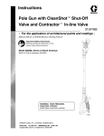
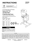
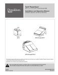
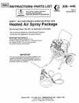
1
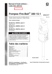
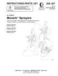
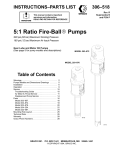
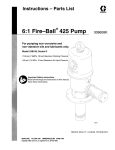
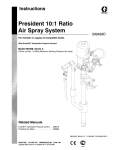
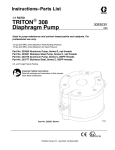
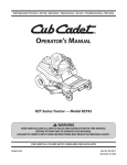
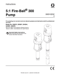
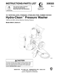
Instructions–Parts List
15:1 Fire-BallR 300 Pumps
306531Z1
For pumping petroleum–based undercoating material.
2700 psi (18.6 MPa, 186 bar) Maximum Working Pressure
180 psi (1.2 Ma, 12 bar) Maximum Air Input Pressure
Model No. 206405, Series K
35 lb. pail size
Model No. 206699, Series J
120 lb. drum size
Model No. 206700, Series J
400 lb. drum size
Important Safety Instructions
Read all warnings and instructions in this manual.
Save these instructions.
WARNING
This product is designed to be used for pumping
non-corrosive and non-abrasive fluids only. Any
other use can cause unsafe operating conditions
and result in component rupture, fire, or explosion,
which can cause serious injury, including skin
injection.
Table of Contents
Warnings . . . . . . . . . . . . . . . . . . . . . . . . . . . . . . . . 2
Installation . . . . . . . . . . . . . . . . . . . . . . . . . . . . . . . 6
Operation . . . . . . . . . . . . . . . . . . . . . . . . . . . . . . . 8
Maintenance . . . . . . . . . . . . . . . . . . . . . . . . . . . . 10
Troubleshooting Guide . . . . . . . . . . . . . . . . . . . 12
Air Motor Service . . . . . . . . . . . . . . . . . . . . . . . . 13
Displacement Pump Service . . . . . . . . . . . . . . 16
Parts . . . . . . . . . . . . . . . . . . . . . . . . . . . . . . . . . . 18
Mounting Hole Layout . . . . . . . . . . . . . . . . . . . . 23
Dimensional Drawings . . . . . . . . . . . . . . . . . . . 23
Technical Data . . . . . . . . . . . . . . . . . . . . . . . . . . 23
Graco Warranty . . . . . . . . . . . . . . . . . . . . . . . . . 24
Graco Phone Numbers . . . . . . . . . . . . . . . . . . . 24
Model 206405 Shown
04208B
Symbols
Caution Symbol
Warning Symbol
WARNING
CAUTION
This symbol alerts you to the possibility of damage to
or destruction of equipment if you do not follow the
instructions.
This symbol alerts you to the possibility of serious
injury or death if you do not follow the instructions.
WARNING
EQUIPMENT MISUSE HAZARD
Equipment misuse can cause the equipment to rupture or malfunction and result in serious injury.
INSTRUCTIONS
D This equipment is for professional use only.
D Read all instruction manuals, tags, and labels before operating the equipment.
D Use the equipment only for its intended purpose. If you are not sure, call your Graco distributor.
D Do not alter or modify this equipment. Use only genuine Graco parts and accessories.
D Check equipment daily. Repair or replace worn or damaged parts immediately.
D Do not exceed the maximum working pressure stated on the equipment or in the Technical Data
for your equipment. Do not exceed the maximum working pressure of the lowest rated component
in your system.
D Use fluids and solvents which are compatible with the equipment wetted parts. Refer to the Technical Data section of all equipment manuals. Read the fluid and solvent manufacturer’s warnings.
D Handle hoses carefully. Do not use hoses to pull equipment.
D Route hoses away from traffic areas, sharp edges, moving parts, and hot surfaces. Do not expose
Graco hoses to temperatures above 66_C (150_F) or below –40_C (–40_F).
D Wear hearing protection when operating this equipment.
D Do not lift pressurized equipment.
D Comply with all applicable local, state, and national fire, electrical, and safety regulations.
2
306531Z1
WARNING
SKIN INJECTION HAZARD
Spray from the gun, leaks or ruptured components can inject fluid into your body and cause extremely
serious injury, including the need for amputation. Fluid splashed in the eyes or on the skin can also
cause serious injury.
D Fluid injected into the skin might look like just a cut, but it is a serious injury. Get immediate
surgical treatment..
D Do not point the gun at anyone or at any part of the body.
D Do not put your hand or fingers over the spray tip.
D Do not stop or deflect leaks with your hand, body, glove or rag.
D Do not “blow back” fluid; this is not an air spray system.
D Always have the tip guard and the trigger guard on the gun when spraying.
D Check the gun diffuser operation weekly. Refer to the gun manual.
D Be sure the gun trigger safety operates before spraying.
D Close the gun ball valves when you stop spraying.
D Lock the gun trigger safety when you stop spraying.
D Follow the Pressure Relief Procedure on page 8 if the spray tip clogs and before cleaning,
checking or servicing the equipment.
D Tighten all fluid connections before operating the equipment.
D Check the hoses, tubes, and couplings daily. Replace worn or damaged parts immediately.
Do not repair high pressure couplings; you must replace the entire hose.
D Fluid hoses must have spring guards on both ends, to help protect them from rupture caused by
kinks or bends near the couplings.
MOVING PARTS HAZARD
Moving parts can pinch or amputate your fingers.
D Keep clear of all moving parts when starting or operating the pump.
D Before checking or servicing the equipment, follow the Pressure Relief Procedure on page 8 to
prevent the equipment from starting unexpectedly.
306531Z1
3
WARNING
FIRE AND EXPLOSION HAZARD
Improper grounding, poor ventilation, open flames or sparks can cause a hazardous condition and
result in a fire or explosion and serious injury.
D Ground the equipment and the object being sprayed. Refer to Grounding on page 7.
D If there is any static sparking or you feel an electric shock while using this equipment, stop spraying immediately. Do not use the equipment until you identify and correct the problem.
D Provide fresh air ventilation to avoid the buildup of flammable fumes from solvents or the fluid
being sprayed.
D Keep the spray area free of debris, including solvent, rags, and gasoline.
D Before operating this equipment, electrically disconnect all equipment in the spray area.
D Before operating this equipment, extinguish all open flames or pilot lights in the spray area.
D Do not smoke in the spray area.
D Do not turn on or off any light switch in the spray area while operating or if fumes are present.
D Do not operate a gasoline engine in the spray area.
TOXIC FLUID HAZARD
Hazardous fluid or toxic fumes can cause serious injury or death if splashed in the eyes or on the skin,
inhaled, or swallowed.
D Know the specific hazards of the fluid you are using.
D Store hazardous fluid in an approved container. Dispose of hazardous fluid according to all local,
state and national guidelines.
D Always wear protective eyewear, gloves, clothing and respirator as recommended by the fluid and
solvent manufacturer.
4
306531Z1
Notes
306531Z1
5
Installation
E
F G
H
J
K
A
B
M
C
D
L
KEY
A
B
C
D
E
F
G
H
J
K
L
M
N
Electrically Conductive Air Hose
Female Quick Disconnect Coupler
Male Quick Disconnect Fitting
Air Line Filter
Air Regulator and Gauge
Bleed-Type Master Air Valve
Air Line Lubricator
Pump Runaway Valve
Pump Air Inlet
Ground Wire
Pressure Drain Valve
Electrically Conductive Fluid Hose
Spray Gun
N
1/2 in.
(13 mm)
04209
Fig. 1
NOTE: Reference numbers and letters in parentheses
in the text refer to the callouts in the figures and the
parts drawings.
Figure 1 is only a guide to selecting and installing
optional and required accessories. For help in designing a system to suit your needs, contact your Graco
distributor.
Mount the pump to suit the type of installation planned.
See page 23 for dimensions and mounting hole layout.
System Accessories
WARNING
To reduce the risk of serious injury including skin
injection, splashing in the eyes or on the skin, and
injury from moving parts, if you are adjusting or
repairing the pump, two accessories are required
in your system: a bleed-type master air valve (F)
and a pressure drain valve (L).
The bleed-type master air valve (F) relieves air
trapped between it and the air motor after the air
supply is shut off. Trapped air can cause the air
motor to cycle unexpectedly if you are adjusting or
repairing the pump. Install the valve near the pump
air inlet, within easy reach of the pump.
The pressure drain valve (L) assists in relieving
fluid pressure in the displacement pump, hoses
and gun. Triggering the spray gun to relieve pressure may not be sufficient.
6
306531Z1
Installation
CAUTION
Provide a bracket for mounting the air accessories.
The fittings are not strong enough to support the
accessories and may cause one or more to break.
D Pump: use a ground wire and clamp as shown
below.
D Truck bed or platform: according to your local code.
D Fluid hoses: use only electrically conductive hoses.
NOTE: Install the accessories in the order shown in
Figure 1.
D Air compressor: follow manufacturer’s recommendations.
D A pump runaway valve (H) shuts off the air to the
pump if the pump accelerates beyond the pre-adjusted setting. A pump which runs too fast can be
seriously damaged.
D Spray gun: grounding is obtained through connection to a properly grounded fluid hose and pump.
D An air line lubricator (G) provides automatic air
motor lubrication.
D Fluid supply container: according to local code.
D A bleed-type master air valve (F) relieves air
trapped between it and the motor when the valve is
closed. Order Part No. 107142.
D The air regulator (E) controls pump speed and
pressure.
D An air line filter (D) removes harmful dirt and
contaminants from your compressed air supply.
D A drain valve (L) is required near the pump fluid
outlet to relieve fluid pressure in the pump, hose
and gun. Order Part No. 210657.
D Object being sprayed: according to local code.
D All solvent pails used when flushing or relieving
pressure, always hold a metal part of the gun firmly
to the side of a grounded metal pail, then trigger the
gun.
To ground the pump:
To ground the pump, use a ground wire and clamp as
shown below. Remove the ground screw (Z) and insert
through the eye of ring terminal at end of ground wire
(Y). Fasten the ground screw back onto the pump and
tighten securely. Connect the other end of the ground
wire to a true earth ground. See Fig. 2. To order a
ground wire and clamp, order Part No. 222011.
D Install an electrically conductive fluid hose (M) and
spray gun (N).
Grounding
Z
Y
Proper grounding is an essential part of maintaining a
safe system.
To reduce the risk of static sparking, ground the pump.
Check your local electrical code for detailed grounding
instructions for your area and type of equipment. Be
sure to ground all of this equipment:
Fig. 2
TI1052
306531Z1
7
Operation
Pressure Relief Procedure
WARNING
SKIN INJECTION HAZARD
The system pressure must be manually
relieved to prevent the system from
starting or spraying accidentally. Fluid
under high pressure can be injected through the
skin and cause serious injury. To reduce the risk of
an injury from injection, splashing fluid, or moving
parts, follow the Pressure Relief Procedure
whenever you:
D
D
D
D
are instructed to relieve the pressure,
stop spraying,
check or service any of the system equipment,
or install or clean the spray tips.
1. Lock the spray gun trigger safety.
2. Close the pump air regulator. Close the bleed-type
master air valve (required in your system).
3. Unlock the gun trigger safety.
4. Hold a metal part of the spray gun firmly to a
grounded metal waste container and trigger the
gun to relieve the fluid pressure.
5. Lock the gun trigger safety.
6. Open the pump drain valve (required with your
system) and leave it open until you are ready to
spray again.
If you suspect that the spray tip or hose is clogged or
that fluid pressure is not fully relieved after following
the steps above, very slowly loosen the tip guard
retaining nut or hose end coupling and relieve pressure
gradually. Clear the tip or hose obstruction.
WARNING
COMPONENT RUPTURE HAZARD
Overpressurizing any component can
result in rupture, fire, explosion, property
damage, and serious injury. To reduce
the risk of overpressurizing, know the Maximum
Working Pressure of the lowest rated component in
your system, and limit the air to the pump so that
you never exceed that pressure.
To determine the fluid output pressure using the air
regulator reading, multiply the pump ratio by the air
pressure you set on the regulator gauge. Example:
15 (:1) ratio x 100 psi air = 1500 psi fluid output
[15 (:1) ratio x 7 bar air = 105 bar fluid output]
8
306531Z1
WARNING
Never operate the pump with the warning plate
(20) or the identification plate (40) removed. These
plates protect your fingers from pinching or amputation by moving parts in the air motor.
Starting and Adjusting the Pump
1. With the air regulator (E) closed, open the bleedtype master air valve (F).
2. Connect the air hose.
3. Trigger the spray gun (N) into a grounded metal
pail, making firm metal-to-metal contact.
4. Open the pump air regulator (E) slowly, just until
the pump is running. When the pump is primed
and all air has been pushed out of the lines, release the spray gun trigger. With sufficient air
supplied, the pump starts when the spray gun is
triggered and shuts off when the trigger is released.
5. Adjust the air regulator just until you get adequate
flow from the spray gun. Always run the pump at
the lowest speed necessary.
CAUTION
Never allow the pump to run dry of the fluid being
pumped. A dry pump will quickly accelerate to a high
speed, possibly damaging itself. If your pump accelerates quickly, or is running too fast, stop it immediately
and check the fluid supply. If the supply container is
empty and air has been pumped into the lines, prime
the pump and lines with fluid, or flush it and leave it filled
with a compatible solvent. Be sure to eliminate all air
from the fluid lines. Use a pump runaway valve (K) to
automatically shut off the pump if it starts to run too fast.
6. Read and follow the instructions supplied with
each component in your system.
7. If the pump will be unattended for any period of
time, or to shut off the system at the end of the
work shift, always follow the Pressure Relief
Procedure, at the left.
Notes
306531Z1
9
Maintenance
Shutdown and General Care
Flushing
WARNING
WARNING
To reduce the risk of serious injury whenever you
are instructed to relieve pressure, always follow the
Pressure Relief Procedure on page 8.
D Always relieve the pressure when you shut down
the pump.
D If you are pumping fluid that dries or sets up, flush
with a compatible solvent as often as necessary to
prevent buildup in the pump and hoses.
D After every 40 hours of operation, adjust the packing nut (42) as described on page 11.
To reduce the risk of serious injury whenever you
are instructed to relieve pressure, always follow the
Pressure Relief Procedure on page 8.
1. To reduce the risk of skin injection, static sparking
or splashing, Relieve the Pressure before flushing.
2. Remove the spray tip.
3. Hold a metal part of the gun firmly to the side of a
grounded metal pail. Use the lowest possible fluid
pressure when flushing.
Lubrication
The accessory air line lubricator (G) provides automatic air motor lubrication. For daily, manual lubrication
follow this procedure:
1. Disconnect the regulator.
2. Place about 15 drops of light machine oil in the
pump air inlet.
3. Reconnect the regulator.
4. Turn on the air supply to blow oil into the motor.
10 306531Z1
Maintenance
Packing Nut Adjustment
WARNING
To reduce the risk of serious injury whenever you
are instructed to relieve pressure, always follow the
Pressure Relief Procedure on page 8.
PISTON
WARNING
Keep your hand and fingers away from the piston
when it is moving. As the piston moves into the
pump base it can amputate fingers or break tools
caught between the moving parts. Note the pinch
point shown in Fig. 3. Be sure all air and fluid
pressure is fully relieved before adjusting the piston
or packing nut to reduce the risk of amputation.
NOTE: Perform this adjustment if: (a) material drips
steadily from the air motor weep hole, which indicates
the packings are too loose, (b) the pump requires more
than 50 psi (.345 MPa, 3.4 bar) air pressure to cycle
when the gun is triggered, which indicates the packings are too tight, or (c) the pump has been in operation for 40 hours.
PINCH POINT
BASE
FLUID
OUTLET
WEEP HOLE LOCATED
OPPOSITE FLUID OUTLET
AND IN BOTTOM OF BASE
Fig. 3
1. Relieve the pressure. Follow the Pressure Relief
Procedure on page 8.
BASE
2. Using a 1/4” nut driver, remove the six screws (24)
from one of the muffler plates (20 or 40) and
remove the muffler plate. See Fig. 4.
3. Check to see that the air motor piston is at the top
of the stroke. If it is not, first read the warning
above. Then, while keeping your fingers away
from moving parts, apply very low pressure air to
the air inlet to move the piston up. Close the air
regulator and disconnect the air supply hose.
Refer to Fig. 3.
20
Fig. 4
24
PACKING NUT
4. Use a 1/4” diameter rod, spanner wrench, or
torque wrench to tighten the packing nut. First
loosen the nut, then tighten snugly, and finally
tighten an additional 1/2 turn (20–25 ft–lbs). See
Fig. 5.
1/4” DIA. ROD
5. Replace the muffler cover, and the six screws.
See Fig. 4.
6. Reconnect the air line. After the pump is started, it
should run at 40 psi (.276 MPa, 2.8 bar) with no
load. Startup may require additional air pressure.
Fig. 5
306531Z1
11
Troubleshooting
WARNING
WARNING
To reduce the risk of serious injury whenever you
are instructed to relieve pressure, always follow the
Pressure Relief Procedure on page 8.
Relieve the Pressure before you check or service any
system equipment.
Never operate the pump with the warning plate
(20) or the identification plate (40) removed. These
plates protect your fingers from pinching or amputation by moving parts in the air motor.
NOTE: Check all other possible problems and solutions before disassembling the pump.
Problem
Cause
Solution
Pump fails to operate
Low air supply pressure or restricted air
lines
Increase air supply; clear*
Closed valves
Open
Clogged fluid lines, hoses, valves, etc.
Clear*
Damaged air motor
Service air motor
Empty fluid supply container
Refill and reprime, or flush
Continuous air exhaust
Worn or damaged air motor gasket,
packing, seal, etc.
Service air motor
Erratic pump operation
Empty fluid supply container
Refill and reprime, or flush
Held open or worn intake valve or
piston packings
Clear; service
Pump operates, but output is low
on the up stroke
Held open or worn piston
or packings
Clear; service
Pump operates, but output is low
on the down stroke
Held open or worn intake valve
Clear; service
Pump operates, but output is low
on both strokes
Low air supply pressure or
restricted air lines
Increase air supply; clear*
Closed valves
Open
Empty fluid supply container
Refill and reprime, or flush
Clogged fluid lines, hoses, valves, etc.
Clear*
Packing nut too tight
Loosen
Loose packing nut or worn packings
Tighten; replace
*Follow the Pressure Relief Procedure on page 8. Disconnect the fluid hose. If the pump starts when the air is
turned on again, the hose or gun is clogged.
12 306531Z1
Air Motor Service
Before you start:
D Have all necessary parts on hand. Always replace
the glands and bearing when replacing the packings. Use all the parts in the repair kits for the best
results. See page 18 to order the kits.
CAUTION
To avoid damaging the cylinder wall, lift the
cylinder (51) straight up off the piston (59). Never tilt the
cylinder as it is being removed.
D Air Motor Repair Kit 206728. Parts included in
this kit are marked with a dagger, (for example,
36†), in the text and drawings.
8. Remove the six screws (25). See Fig. 6. Pull the
cylinder (51) straight up off the piston (59).
D Displacement Pump Repair Kit 206925. Parts
included in this kit are marked with one asterisk,
(i.e., 6*), in the text and drawings.
9. Use a screwdriver to push down on the trip rod
yoke (28), and snap the toggles down. See Fig. 7.
D Two accessory tools should be ordered. Use
Padded Pliers, 207579, to grip the trip rod without
damaging its surface. Use Gauge, 171818, to
ensure the proper clearance between the poppets
and seat of the transfer valve.
Air Motor & Throat Disassembly
47
27
51
54
WARNING
To reduce the risk of serious injury whenever you
are instructed to relieve pressure, always follow the
Pressure Relief Procedure on page 8.
1. Flush the pump.
38
39†
2. Relieve the pressure before proceeding.
42
3. Disconnect the hoses, remove the pump from its
mounting, and clamp the air motor base (55) in a
vise.
4. Use a strap wrench on the riser tube (12) to screw
it out of the air motor base (55).
25
59
44*
1
55
43
5. Pull the connecting rod (10) down as far as it will
go.
6. Use a hammer and punch to remove the roll pin
(4). Unscrew the connecting rod (10). See Fig. 6.
41
10
CAUTION
Do not damage the plated surface of the trip rod (54).
Damaging the surface of the trip rod can result in erratic
air motor operation. Use the special Padded Pliers,
Part Number 207579, to grasp the rod.
7. Manually push up on the piston rod (41) to move
the piston assembly (59) up as far as it will go.
Unscrew the cap nut (47). Pull the nut up. Grip the
trip rod (54) with padded pliers, and screw the nut
off the rod. See Fig. 6.
4*
1
See detail below.
12
50*
48*
2
49*
2
Lips of v-packings must face down.
04210B
Fig. 6
306531Z1
13
Air Motor Service
M
2
30 31 37
54
54
1
28
34†
3
53†
58
45†
35
L
33†
33†
45†
32†
32†
33†
1
36†
0.145”
(3.7 mm)
59
55
58
53†
45†
59
33† 45†
Cutaway View
1
To remove toggles: push in, swing up, ease out.
2
Push toggles (M) in and then up (shown in down position).
3
Turn wires up.
04118
Fig. 7
10. Remove the lockwires (34†) from the adjusting
nuts (33†) of the transfer valves. Screw the top
nuts off. Screw the poppet valve stems (45†) out of
the grommets (32†) and the bottom nuts (30). Take
the valve poppets off the stems and squeeze them
firmly to check for cracks. See Fig. 7.
WARNING
To reduce the risk of pinching or amputating your
fingers, always keep fingers clear of the toggle
assemblies (M).
11. Grip the pivot pins (30) with pliers. Compress the
springs (31), and swing the toggle assembly (M)
up and away from the piston lugs (L). Remove the
parts. Check to see that the valve actuator (35) is
supported by the spring clips (58) but slides easily
into them. See Fig. 7.
12. Remove the trip rod yoke (28), actuator (35) and
trip rod (54). See Fig. 7. Check the exhaust valve
poppets (53†) for cracks. To remove the exhaust
valve poppets (53†), stretch them out and cut them
with a sharp knife.
13. Remove one muffler plate (20 or 40). Pull the
piston (59) up out of the base. Remove the throat
packing nut (42) and packings. See Fig. 6.
14 306531Z1
1
Cut off tops of poppets as indicated by dotted lines.
04119
Fig. 8
Reassembly
1. Clean all the parts in a compatible solvent and
inspect for wear or damage. Check the polished
surfaces of the piston (59), piston rod (41), and
cylinder wall (51) for scratches or wear. A scored
rod will cause premature packing wear and leaking. Use all the repair kit parts and replace other
parts as necessary.
2. Lubricate all parts with a light, waterproof grease.
3. One at a time, install these parts in the base (55):
the gland (49*), five v-packings (48*) with lips
facing down, bearing (50*), backup washer (43),
flat packing (44*), and loosely screw in the packing
nut (42). Be sure the o-rings (38 & 39†) are in
place. See Fig. 6.
4. Pull the exhaust valve poppets (53†) into the valve
actuator (35) and clip off the top part shown with
dotted lines. See Fig. 8.
5. Install the grommets (32†) in the valve actuator
(35). Install the trip rod (54) in the piston (59).
Place the trip rod yoke (28) and valve actuator (35)
on the trip rod. Be sure the o-ring (36*) is in place
and that the valve actuator is supported by the
spring clips (58), and reassemble the valve
mechanism. See Fig. 7.
Air Motor Service
6. Install the bottom adjusting nuts (33) on the poppet
valve stems (45†) and screw the stems into the
grommets (32†). Screw the top nuts (33†) on the
stems. Before installing the lockwires (34†) in the
adjusting nuts, use the gauge 171818 to adjust
the transfer valve so there is 0.145 in. (3.7 mm)
clearance between the poppets and the seat when
it is open. See Fig. 8.
WARNING
To reduce the risk of pinching or amputating your
fingers, always keep fingers clear of the toggle
assemblies (M).
7. Install the springs (31) and pivot pins (30) on the
toggle arms (37). Snap the toggles to the up
position. Refer to Fig. 7.
8. Carefully lower the cylinder (51) over the piston
(59) and onto the base (55). Secure with the six
screws (25).
9. Manually push on the piston rod (41) to move the
piston (59) up as far as it will go. Grip the trip rod
(54) with padded pliers and screw the cylinder cap
nut (47) onto the trip rod. Pull the piston rod (41) to
move the piston down. Be sure the o-ring (27) is in
place at the top of the cylinder (51), and screw the
cap nut into the cylinder.
10. Screw the connecting rod (10) into the piston rod
(41) and secure with the pin (4*). Manually push
on the piston rod (41) to move the piston (59) up
as far as it will go. Screw the riser tube (12) into
the base (55).
11. Use a 1/4” diameter rod, spanner wrench, or
torque wrench to tighten the packing nut (42).
Tighten snugly and then tighten an additional 1/2
turn (20–25 ft–lbs).
12. Install the muffler plate (20 or 40) using the six
screws (24).
13. Connect an air hose and run the pump slowly
[about 30 psi (2.1 bar)] to see that it operates
smoothly.
14. Remount the pump and reconnect the ground wire.
306531Z1
15
Displacement Pump Service
Before you start:
1. Have all necessary parts on hand. Whenever you
replace the packings, also replace the glands and
bearing. If you are using a repair kit, use all the
parts for the best results. See the parts pages to
order the kits.
2. Displacement Pump Repair Kit 206925 includes
repair parts for the pump throat and piston. Parts
included in the kit are marked with one asterisk, for
example (6*), in the text and drawings.
3. To replace the throat packings, which are included
in Repair Kit 206728, refer to the Air
Motor and Throat Disassembly on page 13.
46
Displacement Pump Disassembly
WARNING
To reduce the risk of serious injury whenever you
are instructed to relieve pressure, always follow the
Pressure Relief Procedure on page 8.
†7
1. Flush the pump.
2. Relieve the Pressure
3. Disconnect the hoses, remove the pump from its
mounting, and clamp the air motor base in a vise.
55
*4
4. Unscrew the intake valve body (22) from the riser
tube (12). See Fig. 9. Disassemble the intake
valve.
5. Clean and inspect the parts for wear or damage,
and replace parts as needed. Unless further
service is needed, reassemble and reinstall the
intake valve, using liquid sealant on the male
threads. See Fig. 9.
16 306531Z1
10
*4
14
2*
*19
*6
*17
6. Use a strap wrench on the riser tube (12) to screw
it out of the air motor base (55). Carefully inspect
the smooth inner surface of the cylinder for scoring
or irregular surfaces. Such damage causes premature packing wear and leaking, so replace the part
if damaged.
7. Unscrew the piston body (13) from the piston
coupling (14). Remove the ball (2*), seat (19*),
gasket (6*), bearing (18*), packing (17*), and seal
(16). Do not remove the press-fit brass bearing
(15*). See Fig. 9.
12
18*
*15
13
16*
22
21
7
Fig. 9
3*
04212B
Displacement Pump Service
NOTE: If the pressure-fit brass bearing (15*) needs to
be replaced, clamp it in a vise and drive the piston
body (13) out with a plastic hammer. The new bearing
must be started onto the piston body squarely.
8. Clean and inspect the parts and replace any that
are worn or damaged. Be sure to check the copper
gasket (46) in the motor base (55). Lubricate the
parts with a light waterproof grease.
10. Install the gasket (7*[). Screw the riser tube (12)
into the air motor base (55).
11. Reinstall the ball (3*), gasket (7), ball stop (21) and
other gasket (7) in the intake valve housing (22).
Screw the housing onto the riser tube (12).
12. Be sure the ground wire is connected before
regular operation of the pump.
9. Install the seal (16*), packing (17*), bearing (18*),
gasket (6*), seat (19*) and ball (2*) on the piston
body (13). The check ball seat (19*) may be reversed to provide a new seat. Screw the piston
body (13) into the piston coupling (14).
306531Z1
17
Parts
Model 206405, Series K
35 lb. pail size
39†
38
47
40
55
27
25
51
60
63
28
34†
35
29
10
33†
37
53†
31
30
20
24
14
32†
33†
57
54
58
59
*4
2*
19*
6*
18*
†36
17*
16*
46
45†
15*
13
41
7*†
*4
42
12
44*
43
50*
7
21
7
48*
49*
3*
22
04213B
18 306531Z1
Parts
Model 206405, Series K
35 lb. pail size
Ref
No.
Part No.
2*
3*
4*
100114
100400
101579
6*
7*†
150451
150694
10
165970
12
165971
13
14
15*
16*
17*
18*
19*
20**
21
22
24**
160939
160940
160941
160942
160943
160944
160945
234578
183326
191080
100078
25
101578
27
28
29
30
31
32†
33†
34†
35
36†
156698
158360
158362
158364
167585
158367
160261
160618
172867
160621
Description
Qty.
BALL, steel, 0.44” (11.2 mm) dia. 1
BALL, steel, 0.75” (19 mm) dia.
1
PIN, roll, 0.12” (3.2 mm) dia.,
0.75” (19 mm) long
3
GASKET, copper
1
GASKET, copper
(qty 1 in kits 206925 and 206728) 3
ROD, connecting,
5 1/4” (133 mm) long
1
TUBE, riser,
11–11/16” (297 mm) long
1
BODY, piston
1
COUPLING, piston
1
BEARING, press fit, brass
1
SEAL, piston; PTFE
1
PACKING, block, nitrile rubber
1
BEARING, piston, brass
1
SEAT, piston, reversible
1
PLATE, warning (with muffler)
1
STOP, ball
1
HOUSING, intake valve
1
. SCREW, hex washer hd, mach,
8–32 x 3/8”
12
. CAPSCREW, hex hd Nylockr,
5/16–18 x 7/8”
6
. O-RING, nitrile rubber
1
. YOKE, rod, trip
1
. PIN, toggle
2
. PIN, pivot
2
. SPRING, helical compression
2
. GROMMET; rubber
2
. NUT, adjusting
4
. WIRE, lock
2
. ACTUATOR, valve
1
. O-RING, nitrile rubber
1
Ref
No.
Part No.
37
38
39†
40**
160623
160624
160625
234577
41
42
43
44*
45†
46
47
48*
49*
50*
51
53†
54
55
57
160639
160640
160641
160644
236079
160932
164704
162391
168851
168852
160613
170709
203965
204896
102975
58
59
60
63
172866
15K534
116343
162718
Description
Qty.
. ARM, toggle
. O-RING, nitrile rubber
. O-RING, nitrile rubber
. PLATE, identification,
with muffler
. ROD, piston
. NUT, packing
. WASHER, backup
. PACKING, flat leather
. VALVE, poppet
. GASKET, copper
. NUT, cylinder cap
. V-PACKING, leather
. GLAND, male
. BEARING, throat
. CYLINDER, air motor
. POPPET, valve, urethane
. ROD, trip
. BASE, air motor
. SCREW, rd hd mach,
6–32 x 1/4”
. CLIP, spring
. PISTON, air motor
. SCREW, ground
. ADAPTER, 3/8 npt (m) x
1/4 npt(f)
2
1
1
1
1
1
1
1
2
1
1
5
1
1
1
2
1
1
2
2
1
1
1
* These parts are included in Pump Repair Kit 206925,
which may be purchased separately.
** These parts are included in Muffler Repair Kit 222559,
which may be purchased separately.
† These parts are included in Air Motor Repair Kit 206728,
which may be purchased separately.
306531Z1
19
Parts
Model 206699, Series J
120 lb. drum size
39†
40
Model 206700, Series J
400 lb. drum size
47
38
27
55
25
51
60
35
63
28
29
34†
37
33†
10
31
53†
30
20
24
14
*4
2*
32†
33†
57
58
54
19*
6*
59
18*
17*
†36
16*
45†
46
15*
13
41
7*†
*4
42
44*
12
43
50*
48*
49*
7
21
7
3*
22
04214B
20 306531Z1
Parts
Model 206699, Series J
120 lb. drum size
Ref.
No.
Part No.
2*
3*
4*
100114
100400
101579
6*
7*†
150451
150694
10
160688
161050
12
160938
161051
13
14
15*
16*
17*
18*
19*
20**
21
22
24**
160939
160940
160941
160942
160943
160944
160945
234578
183326
191080
100078
25
101578
27
28
29
30
31
32†
156698
158360
158362
158364
167585
158367
Description
Model 206700, Series J
400 lb. drum size
Qty.
BALL, steel, 0.44” (11.2 mm) dia. 1
BALL, steel, 0.75” (19 mm) dia.
1
PIN, roll, 0.12” (3.2 mm) dia.,
0.75” (19 mm) long
3
GASKET, copper
1
GASKET, copper
(qty 1 in kits 206925 and 206728) 3
ROD, connecting,
18–15/16” (481 mm) long
1
(For Model 206699)
ROD, connecting,
25 7/8” (657 mm) long
1
(For Model 206700)
TUBE, riser,
25–3/8” (645 mm) long
1
(For Model 206699)
TUBE, riser,
32 5/16” (821 mm) long
1
(For Model 206700)
BODY, piston
1
COUPLING, piston
1
BEARING, press fit, brass
1
SEAL, piston; PTFE
1
PACKING, block, nitrile rubber
1
BEARING, piston, brass
1
SEAT, piston, reversible
1
PLATE, warning (with muffler)
1
STOP, ball
1
HOUSING, intake valve
1
. SCREW, hex washer hd, mach,
8–32 x 3/8”
12
. CAPSCREW, hex hd Nylock,
5/16–18 x 7/8”
6
. O-RING, nitrile rubber
1
. YOKE, rod, trip
1
. PIN, toggle
2
. PIN, pivot
2
. SPRING, helical compression
2
. GROMMET; rubber
2
Ref.
No.
Part No.
33†
34†
35
36†
37
38
39†
40**
160261
160618
172867
160621
160623
160624
160625
234577
41
42
43
44*
45†
46
47
48*
49*
50*
51
53†
54
55
57
160639
160640
160641
160644
236079
160932
161435
162391
168851
168852
160613
170709
203965
204896
102975
58
59
60
63
172866
15K534
116343
162718
Description
Qty.
. NUT, adjusting
. WIRE, lock
. ACTUATOR, valve
. O-RING, nitrile rubber
. ARM, toggle
. O-RING, nitrile rubber
. O-RING, nitrile rubber
. PLATE, identification,
with muffler
. ROD, piston
. NUT, packing
. WASHER, backup
. PACKING, flat leather
. VALVE, poppet
. GASKET, copper
. NUT, cylinder cap
. V-PACKING, leather
. GLAND, male
. BEARING, throat
. CYLINDER, air motor
. POPPET, valve, urethane
. ROD, trip
. BASE, air motor
. SCREW, rd hd mach,
6–32 x 1/4”
. CLIP, spring
. PISTON, air motor
. SCREW, ground
. ADAPTER, 3/8 npt (m) x
1/4 npt(f)
4
2
1
1
2
1
1
1
1
1
1
1
2
1
1
5
1
1
1
2
1
1
2
2
1
1
1
* These parts are included in Pump Repair Kit 206925,
which may be purchased separately.
** These parts are included in Muffler Repair Kit 222559,
which may be purchased separately.
† These parts are included in Air Motor Repair Kit 206728,
which may be purchased separately.
306531Z1
21
Notes
22 306531Z1
Dimensions
Technical Data
3/8 npt(f)
Air Inlet
1/4 npt(f)
Fluid Outlet
Model
206405
13 inches
(330 mm)
Model
206699
26.69 inches
(677.7 mm)
Maximum Working Pressure . . . . . . 2700 psi (186 bar)
Fluid pressure ratio . . . . . . . . . . . . . . . . . . . . . . . . . . 15:1
Air operating range . . . . . . . 40 to 180 psi (3 to 12 bar)
Air motor effective diameter . . . . . . . . . . . 3 in. (76 mm)
Stroke . . . . . . . . . . . . . . . . . . . . . . . . . . . . . 3 in. (76 mm)
Air consumption . . . . 17 cfm/gallon pumped at 100 psi
(0.476 m3/liter at 7 bar);
up to 30 cfm with pump operated
at 180 psi and 66 cycles/min.
(up to 0.84 m3/min with pump operated
at 12 bar and 66 cycles/min.)
Pump cycles per gallon (liter) . . . . . . . . . . . . . . . 90 (24)
Delivery . . . . . . . . 0.66 gallons/minute (3 liters/minute)
Maximum recommended
pump speed . . . . . . . . . . . . . . . . . . . . . . . 66 cycles/min;
0.7 gpm (32 liter/min)
Recommended speed
for optimum pump life . . . . . . . 15 to 25 cycles per min
Wetted parts . . . . . . . . . . . . . . . . . . Carbon Steel, Brass,
Copper, Aluminum,
PTFE, Nitrile Rubber, Leather
Approximate weight . . . . . . . . . . . . . . . . . . . 22 lb (10 kg)
Model
206700
33.62 inches
(854 mm)
04217B
Mounting Hole Layout
2 Hole Mounting
Pattern
4 Hole Mounting
Pattern
161023 Gasket
Two or Four
0.265” (7 mm)
Dia. Holes on 5”
(127 mm) Bolt Circle
3” (76.2 mm) Dia.
04127
306531Z1
23
Graco Standard Warranty
Graco warrants all equipment manufactured by Graco and bearing its name to be free from defects in material and workmanship on the
date of sale to the original purchaser for use. With the exception of any special, extended, or limited warranty published by Graco,
Graco will, for a period of twelve months from the date of sale, repair or replace any part of the equipment determined by Graco to be
defective. This warranty applies only when the equipment is installed, operated and maintained in accordance with Graco’s written
recommendations.
This warranty does not cover, and Graco shall not be liable for general wear and tear, or any malfunction, damage or wear caused by
faulty installation, misapplication, abrasion, corrosion, inadequate or improper maintenance, negligence, accident, tampering, or substitution of non–Graco component parts. Nor shall Graco be liable for malfunction, damage or wear caused by the incompatibility of
Graco equipment with structures, accessories, equipment or materials not supplied by Graco, or the improper design, manufacture,
installation, operation or maintenance of structures, accessories, equipment or materials not supplied by Graco.
This warranty is conditioned upon the prepaid return of the equipment claimed to be defective to an authorized Graco distributor for
verification of the claimed defect. If the claimed defect is verified, Graco will repair or replace free of charge any defective parts. The
equipment will be returned to the original purchaser transportation prepaid. If inspection of the equipment does not disclose any defect
in material or workmanship, repairs will be made at a reasonable charge, which charges may include the costs of parts, labor, and
transportation.
THIS WARRANTY IS EXCLUSIVE, AND IS IN LIEU OF ANY OTHER WARRANTIES, EXPRESS OR IMPLIED, INCLUDING BUT
NOT LIMITED TO WARRANTY OF MERCHANTABILITY OR WARRANTY OF FITNESS FOR A PARTICULAR PURPOSE.
Graco’s sole obligation and buyer’s sole remedy for any breach of warranty shall be as set forth above. The buyer agrees that no other
remedy (including, but not limited to, incidental or consequential damages for lost profits, lost sales, injury to person or property, or any
other incidental or consequential loss) shall be available. Any action for breach of warranty must be brought within two (2) years of the
date of sale.
Graco makes no warranty, and disclaims all implied warranties of merchantability and fitness for a particular purpose in connection
with accessories, equipment, materials or components sold but not manufactured by Graco. These items sold, but not manufactured
by Graco (such as electric motors, switches, hose, etc.), are subject to the warranty, if any, of their manufacturer. Graco will provide
purchaser with reasonable assistance in making any claim for breach of these warranties.
In no event will Graco be liable for indirect, incidental, special or consequential damages resulting from Graco supplying equipment
hereunder, or the furnishing, performance, or use of any products or other goods sold hereto, whether due to a breach of contract,
breach of warranty, the negligence of Graco, or otherwise.
FOR GRACO CANADA CUSTOMERS
The parties acknowledge that they have required that the present document, as well as all documents, notices and legal proceedings
entered into, given or instituted pursuant hereto or relating directly or indirectly hereto, be drawn up in English. Les parties reconnaissent avoir convenu que la rédaction du présente document sera en Anglais, ainsi que tous documents, avis et procédures judiciaires
exécutés, donnés ou intentés à la suite de ou en rapport, directement ou indirectement, avec les procedures concernées.
Graco Phone Numbers
For the latest information about Graco products, visit www.graco.com.
TO PLACE AN ORDER, contact your Graco distributor, or call one of the following numbers
to identify the distributor closest to you:
1–800–533–9655 Toll Free
612–623–6928
612–378–3590 Fax
All written and visual data contained in this document reflects the latest product information available at the time of publication.
Graco reserves the right to make changes at any time without notice.
This manual contains English. MM 306531
Graco Headquarters: Minneapolis
International Offices: Belgium, China, Japan, Korea
GRACO INC. P.O. BOX 1441 MINNEAPOLIS, MN 55440–1441
Copyright 1996, Graco Inc. is registered to ISO 9001
www.graco.com
Revised 05/2009
24 306531Z1