1
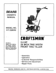
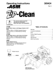
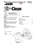
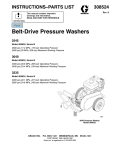
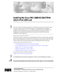
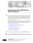
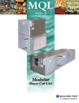
Instructions
Important Safety Instructions.
Read all warnings and instructions in this
manual. Save these instructions.
Direct Drive Pressure Washer
309286K
- For high pressure water cleaning Models:
Maximum Working
Pressure
Operating Pressure
Model
Horse Power and
Motor Brand
6.5 hp Briggs &
Stratton
2700
18.6
186
3000
20.6
206
2730B
2730H
6.5 hp Honda
2700
18.6
186
3000
20.6
206
3030
9 hp Honda
3000
20.6
206
3300
22.75
227.5
3340
11 hp Honda
3300
22.75
227.5
3600
24.0
248
3540
13 hp Honda
3500
24.1
241
3800
26.2
262
PSI
MPa
bar
PSI
ti5418a
Graco Inc. P.O. Box 1441 Minneapolis, MN 55440-1441
Copyright 2004, Graco Inc. is registered to I.S. EN ISO 9001
MPa
bar
Warnings
Warnings
WARNING
FIRE AND EXPLOSION HAZARD
Flammable fumes, such as solvent and paint fumes, in work area can ignite or explode. To help prevent
fire and explosion:
• Use equipment only in well ventilated area.
• Do not fill fuel tank while engine is running or hot; shut off engine and let it cool. Fuel is flammable
and can ignite or explode if spilled on hot surface.
• Eliminate all ignition sources; such as pilot lights, cigarettes, portable electric lamps, and plastic drop
cloths (potential static arc).
• Keep work area free of debris, including solvent, rags and gasoline.
• Do not plug or unplug power cords, or turn power or light switches on or off when flammable fumes
are present.
• Ground equipment and conductive objects in work area. See Grounding instructions.
• Use only grounded hoses.
• Hold gun firmly to side of grounded pail when triggering into pail.
• If there is static sparking or you feel a shock, stop operation immediately. Do not use equipment
until you identify and correct the problem.
• Keep a fire extinguisher in the work area.
INJECTION HAZARD
High-pressure fluid from gun, hose leaks, or ruptured components will pierce skin. This may look like just
a cut, but it is a serious injury that can result in amputation. Get immediate surgical treatment.
• Do not point gun at anyone or at any part of the body.
• Do not put your hand over the end of the spray tip.
• Do not stop or deflect leaks with your hand, body, glove, or rag.
• Follow Pressure Relief Procedure in this manual, when you stop spraying and before cleaning,
checking, or servicing equipment.
EQUIPMENT MISUSE HAZARD
Misuse can cause death or serious injury.
• Do not exceed the maximum working pressure or temperature rating of the lowest rated system
component. See Technical Data in all equipment manuals.
• Use fluids and solvents that are compatible with equipment wetted parts. See Technical Data in all
equipment manuals. Read fluid and solvent manufacturer’s warnings.
• Check equipment daily. Repair or replace worn or damaged parts immediately.
• Do not alter or modify equipment.
• Use equipment only for its intended purpose. Call your Graco distributor for information.
• Route hoses and cables away from traffic areas, sharp edges, moving parts, and hot surfaces.
• Do not use hoses to pull equipment.
• Keep children and animals away from work area.
• Comply with all applicable safety regulations.
CARBON MONOXIDE HAZARD
Exhaust contains poisonous carbon monoxide, which is colorless and odorless. Breathing carbon monoxide can cause death. Do not operate in an enclosed area.
2
309286K
Warnings
WARNING
TOXIC FLUID OR FUMES HAZARD
Toxic fluids or fumes can cause serious injury or death if splashed in the eyes or on skin, inhaled, or
swallowed.
• Read MSDS’s to know the specific hazards of the fluids you are using.
• Store hazardous fluid in approved containers, and dispose of it according to applicable guidelines.
PERSONAL PROTECTIVE EQUIPMENT
You must wear appropriate protective equipment when operating, servicing, or when in the operating
area of the equipment to help protect you from serious injury, including eye injury, inhalation of toxic
fumes, burns, and hearing loss. This equipment includes but is not limited to:
• Protective eyewear
• Clothing and respirator as recommended by the fluid and solvent manufacturer
• Gloves
• Hearing protection
309286K
3
Component Identification
Component Identification
A
D
C
B
M
E
L
K
F
A
J
H
G
Key:
A
B
C
D
E
F
G
4
Hose
Hose Rack
Gun Holder
Gun and Wand
Tip Storage
Engine Oil Fill
Water Pump Oil Fill
H
J
K
L
M
Oil Level Site Gage
Pressure Unloader Adjustment Knob
Garden Hose Connection
High Pressure Hose Connection
Engine ON/OFF Switch
309286K
Setup
Setup
Shipping Damage
Connect to Water Supply
Check pressure washer for shipping damage. Notify the
carrier immediately if there is any damage.
Connect hose from water supply to the garden hose
inlet on the pressure washer.
Connecting High-Pressure Hose and Gun
•
Connect high-pressure hose between pump outlet and
gun inlet. Both of these connections are made with quick
couplers.
•
The supply hose should not be longer than 50
ft (15 m) in length.
Inside diameter of hose should measure at
least a 3/4 in. (19 mm).
ti5422a
ti5420a
•
Up to 100 ft (30 m) of 3/8 in. high-pressure hose
may be used. Longer hoses could affect pressure
washer and chemical injector performance
balance.
Installing Spray Tip
•
•
Install spray tip on wand. (Installing and Changing Spray
Tips, page.) If you are using a Sandblasting Kit, see its
separate manual for installation instructions.
CAUTION
Before you connect garden hose to pressure
washer, check your local plumbing code regarding
cross-connection to the water supply. If required,
install a backflow preventer.
If the inlet water pressure is over 60 psi (4.1 bar, 41
MPa), a regulating water valve must be installed at
the garden hose connection.
Do not exceed 160° F (70° C) inlet water temperature.
The water source must have a minimum flow rate
equal to that of the pressure washer.
ti5421a
309286K
5
Operation
Operation
Pressure Relief Procedure
4. Turn off water supply and disconnect pressure
washer from water.
Follow this procedure when you stop spraying and
before cleaning, checking, servicing or transporting
equipment.
ti5425a
1. Engage trigger lock.
5. Unlock trigger lock. Trigger gun to relieve pressure.
Engage trigger lock.
TIA
2. Turn pressure washer OFF.
ti5427a
ON
OFF
ti5424a
If you suspect the spray tip or hose is clogged or
that pressure has not been fully relieved after following the pressure relief procedure, VERY
SLOWLY loosen tip guard retaining nut or hose end
coupling to relieve pressure gradually, then loosen
completely. Clear hose or tip obstruction.
3. Remove ignition cap from spark plug.
6
309286K
Operation
Startup
•
Always engage the gun trigger safety latch when
you stop spraying. This reduces the risk of fluid
injection or splashing in eyes or on skin if the gun is
bumped or triggered accidentally. Be sure latch is
pushed fully down or it will not prevent the gun from
being triggered.
3. Check oil level in pump. It should be half way up the
sight glass, located on the front of the pump. Add
pump oil as necessary. The system is equipped with
a thermal overload to help prevent severe damage.
Oil level
ti5430a
ti5437a
After the first 50 hours of operation, drain and refill
pump oil.
engaged
•
disengaged
4. Turn on water supply.
When using a sandblasting kit, refer the sandblaster
kit instruction manual for detailed operating and
cleaning information.
1. Check oil level of engine and pump.
ti5431a
ti5428a
•
•
•
All Honda engine-powered pressure washers
are equipped with an engine low-oil sensor that
shuts the engine off when the oil level falls
below a certain level.
If the engine stops unexpectedly, check the oil
and fuel levels.
Check the oil level each time you add fuel.
.
CAUTION
Always be sure the water supply is completely turned
on before you run the pressure washer. Never run
pressure washer without water. Costly pump damage
will result.
5. Trigger gun until a constant stream of water sprays
from the tip, indicating air is purged from the system.
6. Open fuel shutoff valve. Be sure spark plug ignition
cable is pushed firmly on the spark plug.
2. Check fuel level.
Fuel level
ON
ti5433a
ti5429a
309286K
7
Operation
7. Move switch to ON position and set throttle to HALF
throttle position.
•
•
OFF
ON
•
ti5434a
•
•
•
•
CAUTION
Do not allow pressure washer to idle for more than
10 minutes. This causes the recirculating water to
overheat and can seriously damage the pump.
Turn off pressure washer if it will not be spraying at
least every 10 minutes. If heated inlet water is used,
reduce this time more.
Do not operate pressure washer with inlet water
screen removed. This screen help keep abrasive
sediment out of pump. This sediment could clog
pump or damage cylinders. Keep screen clean.
Do not pump caustic materials which could corrode
pump components.
8. Trigger gun to produce a constant stream of water
and, at the same time, pull starter rope quickly to
start the engine. Pull and return rope until the
engine starts. HINT: Placing one foot on the pressure washer as a brace provides better leverage.
For easier starting, have one person start pressure washer while another triggers gun.
If engine is cold, before starting engine, close
choke completely. In cool weather you might
have to run engine for the first 10-30 seconds
with the choke closed. In warm weather, open
choke completely as soon as engine starts.
If engine is warm, start engine with choke
completely open or only partially closed. When
engine starts, open choke completely.
HALF
CLOSED
OPEN
ti5436a
Chemical Injector Operation
1. Follow Pressure Relief Procedure (page 6).
2. Insert chemical filter (attached with clear tubing to
chemical injector) into the chemical container. Insert
brass coupler into chemical injector.
ti5438a
ti5435a
8
309286K
Operation
3. Install black (large orifice) chemical tip (Installing
and Changing Spray Tips, page 9).
The large orifice of the chemical tip causes a drop
in pressure that actuates the chemical injector.
Changing back to a small orifice spray tip, deactivates the chemical injector and produces high pressure for rinsing. The chemical filter can be left in the
chemical container during high pressure spraying.
To regulate the flow rate of the chemical, turn the
chemical adjustment knob on the injector.
ti5439a
Installing and Changing Spray
Tips
Spray tips have 4- or 5-digit numbers on them. The first
two digits are the spray angle.
Spray Tip No.
00XXX
15XXX
25XXX
40XXX
Chemical*
Spray Pattern Fan Angle
0° blaster (red)
15° (yellow)
25° (green)
40° (white)
XX° (black)
*The chemical injector tip is brass and has a larger
opening and a black plastic cap.
1. Follow Pressure Relief Procedure, page 6.
2. Lock trigger safety.
3. Without holding your hand over the spray tip (A), pull
back the quick coupler ring (B). Remove the current
tip. Install a different tip. Push quick coupler ring
back into place.
B
A
ti5440a
CAUTION
To avoid the high pressure blowing the o-ring out of
the quick coupler, never operate the pressure washer
without a tip securely mounted in the quick coupler.
309286K
9
Shutdown, Flushing and Storage
Shutdown, Flushing and Storage
Short-term Storage (less than 30
days)
Long-term (more than 30
days)/Winter Storage
•
•
Do not store unit outside where it can be exposed to
rain, dirt or adverse weather conditions.
•
Do not expose pressure washer to freezing temperatures or allow water to freeze in pressure washer
components which could cause the pump to
lock-up. If this happens, allow the pump to thaw naturally in a WARM ENVIRONMENT. Do not attempt
to speed up this process by pouring warm water on
the pump. This could cause additional damage to
the pump.
Before you store the pressure washer overnight or
transport it, disconnect the water supply and
CLOSE the fuel supply valve.
ti5441a
•
After each use, wipe all pressure washer surfaces
with a clean, damp cloth.
ENGINE:
1. Run engine until gas is gone or stabilize fuel and run
it through fuel system and carburetor.
2. Drain water out of pressure washer hose.
3. Turn fuel system of OFF position.
PUMP:
1. Place an antifreeze solution approximately 1 foot off
the ground. Attach one end of a 4- or 5-foot section
of hose to pump inlet and other end in the antifreeze
solution.
ti5442a
2. Pull starter rope on engine until antifreeze comes
out of pump outlet.
STORAGE LOCATION
Store pressure washer in garage, basement, or in an
area where it is protected from freezing temperatures.
10
309286K
Maintenance Chart
Maintenance Chart
Follow Pressure Relief Procedure, page 6.
Interval
Daily
What to do
• Clean water inlet screen and filter.
• Check engine and pump oil levels. Fill as necessary.
• Check gasoline level. Fill as necessary.
After first 5 hours of Change engine break-in oil. Drain oil when warm. Use SAE 30 or10W-30 detergent oil.
operation
After every 25 hours Clean and remove air cleaner foam. Wash with water and detergent. Dry thoroughly. Rub with
of operation
oil and squeeze to distribute oil.
After first 50 hours Change pump break-in oil. Use approved SAE 20/30 pump oil.
of operation
After every 100
• Clean or replace paper air cleaner cartridge. Tap gently to remove dirt.
hours of operation or • Change engine oil. Use SAE 30 or 10W-30 detergent oil.
every 3 months
Change pump oil. Use approved SAE 20/30 pump oil.
After every 500
hours of operation or
every 6 months
309286K
11
Troubleshooting
Troubleshooting
T
Problem
Engine will not start or it is hard to
start
Cause
Solution
No gasoline in fuel tank or carburetor Fill tank with gasoline, open fuel shutoff valve. Check fuel line and carburetor.
Low oil
Add oil to proper level.
Engine ON/OFF switch in OFF position
Turn switch to ON position.
Water in fuel or old fuel
Drain fuel tank and carburetor. Use
new fuel and make sure spark plug is
dry.
Engine flooded or improperly choked Open choke. Pull engine starter rope
several times to clear out fuel. Make
sure spark plug is dry.
Dirty air cleaner filter
Remove and clean filter.
Spark plug dirty, wrong gap or wrong Clean, adjust gap or replace spark
type
plug.
Engine misses or lacks power
Gun not triggered
Trigger gun while starting engine.
6.5 hp Briggs and Stratton model
may experience “vapor lock” due to
gas type and temperature
Allow unit to cool approximately 15
minutes and restart.
Partially plugged air cleaner filter
Remove and clean.
Valve adjustment (lash) worn
Adjust valve (lash) to manufacturer’s
specifications.
Spark plug dirty, wrong gap or wrong Clean, adjust gap or replace spark
type
plug.
Pressure is too low and/or pump runs Worn or wrong size tip
roughly
Inlet filter clogged
Replace with tip of proper size.
Clean. Check more frequently.
Worn packings, abrasives in water or Check filter. Replace packing.
natural wear
Inadequate water supply
Check water flow rate to pump.
Fouled or dirty inlet or discharge
valves
Clean inlet and discharge valve
assemblies. Check filter.
Restricted inlet
Garden hose might be collapsed or
kinked. Check hose and straighten to
remove kinks.
Worn inlet or discharge valves
Replace worn valves.
Leaking high-pressure hose
Replace high-pressure hose.
Water leaks from under pump manifold
Worn packings
Install new packings.
Water on oil side of pump
Humid air condensing inside crankcase
Change oil as specified in Maintenance Chart, page 11.
Worn packings
Install new packings.
Oil seals leaking
Install new oil seals.
12
309286K
Troubleshooting
Problem
Cause
Packings are failing frequently or pre- Scored, damaged, or worn plungers
maturely
Abrasive material in fluid being
pumped
Inlet water temperature too high
Solution
Install new plungers.
Install proper filtration on pump inlet
plumbing.
Check water temperatures. It should
not exceed 160°F (70°C).
Pump running too long without spray- Never run pump more than 10 mining
utes without spraying.
Running pump dry
Strong surging at inlet and low pressure on discharge side
309286K
Do not run pump without water.
Foreign particles in inlet or discharge Clean or replace valves.
valve or worn inlet and/or discharge
valves
13
Pump Service: 2730B/2730H Model Pressure Washers
Pump Service: 2730B/2730H Model Pressure Washers
Repair kits are available. See the Parts List, page 18 (2730B) or page 20 (2830H). For the best results, use all parts
in kits.
Servicing Plungers
•
•
The following metric wrenches are needed:
5mm, 13mm, and 22mm.
Drain and refill pump after 50 hours of operation.
Follow Pressure Relief Procedure, page 6.
Valves
For a set of six valves, order Valve Assembly Kit
804402.
1. Remove hex plug from the manifold using a 22mm
wrench.
2. Examine o-ring located under hex plug. Replace if
cut or distorted.
3. Remove valve assembly from cavity. The assembly
may come apart!
4. Install new valve, o-ring and hex plug. Torque to 33
ft-lb (45 N◆m).
Retorque the plug after 5 hours operation.
Pumping Section
1. Remove capscrews and lock washers from manifold
using a 5mm wrench.
2. Carefully separate manifold from the crankcase. You
may have to lightly tap the manifold with a soft mallet to loosen it.
CAUTION
To avoid damage to plunger or seals, keep manifold
properly aligned with the ceramic plungers when you
remove it.
3. Carefully examine each plunger for any scoring or
cracking. Replace as necessary.
1. Loosen plunger retaining nut five or six turns using a
13mm wrench. Push plunger toward the crankcase
to separate plunger and retaining screw.
2. Remove nut from plunger and examine and clean
o-ring, backup ring, and copper bearing/gasket
washer.
3. Remove plunger and flinger from plunger shaft.
Clean parts as necessary.
4. Inspect plunger shaft for oil leaks from crankcase. If
leaking is obvious, replace oil seals. Otherwise, DO
NOT remove these seals because they cannot be
reused. Oil Seal Kits are available for replacing
seals.
5. Lightly grease the flinger (and oil seal if it is being
replaced) on plunger shaft. Then install plunger.
6. Lightly grease the retaining screw and outer end of
the plunger. Place washer, o-ring and backup ring
around screw and install nut through plunger.
Torque to 11 ft-lb (15 N◆m).
If replacing packings, see Servicing V-Packings,
page 15.
7. Lubricate outside of each plunger. Slide the manifold on the crankcase, being careful not to damage
seals.
8. Install capscrews and washers finger tight. Torque
screws to 8.8 ft-lb (12 N◆m) following the tightening
pattern in the following figure.
5
1
4
7
8
3
2
6
ti5443a
14
309286K
Pump Service: 2730B/2730H Model Pressure Washers
Uneven tightening could cause the manifold to bind
or jam.
Servicing V-Packings
1. Remove manifold as described in Pumping Section,
page 14.
2. Carefully pull packing retainer from manifold. Examine o-ring. Replace o-ring if cut or damaged.
3. Remove V-packing and head ring. Pull out retainer
ring. Remove second V-packing and second head
ring.
4. Inspect all parts and replace as necessary.
5. Thoroughly clean packing cavities and inspect for
damage.
309286K
6. Lightly grease packing cavities. Replace packings in
the following order:
•
•
•
•
•
•
•
head ring
v-packing
intermediate ring
head ring
v-packing
packing retainer
o-ring in retainer groove
Packings must be installed in the proper order and
facing the correct direction. Improperly installed
parts will cause the pump to malfunction.
7. Reassemble manifold following procedure
described in Servicing Plungers, page 14.
15
Pump Service: 3030, 3340, and 3540 Model Pressure Washers
Pump Service: 3030, 3340, and 3540 Model Pressure
Washers
Repair kits are available. See the Parts List, page 22. For the best results, use all parts in kits.
3. Carefully examine each plunger for any scoring or
cracking. Replace as necessary.
Servicing Plungers
Follow Pressure Relief Procedure, page 6.
•
•
The following metric wrenches are needed:
6mm, 13mm, and 27mm.
Drain and refill pump after 50 hours of operation.
Valves
For a set of six valves, order Valve Assembly Kit
804402.
1. Remove hex plug from the manifold using a 27mm
wrench.
2. Examine o-ring located under hex plug. Replace if
cut or distorted.
3. Remove valve assembly from cavity. The assembly
may come apart!
4. Install new valve, o-ring and hex plug. Torque to 73
ft-lb (99 N◆m).
Plunger Repair Kit 243430 is available to replace retainers, o-rings, washers, and backup rings for three cylinders.
1. Loosen plunger retaining nut five or six turns using a
13mm wrench. Push plunger toward the crankcase
to separate plunger and retaining screw.
2. Remove nut from plunger and examine and clean
o-ring, backup ring, and copper bearing/gasket
washer. Replace these parts if necessary using
Plunger Repair Kit 243430.
3. Remove plunger and flinger from plunger shaft.
Clean parts as necessary.
4. Inspect plunger shaft for oil leaks from crankcase. If
leaking is obvious, replace oil seals. Otherwise, DO
NOT remove these seals because they cannot be
reused. Oil Seal Kits are available for replacing
seals.
5. Lightly grease the flinger (and oil seal if it is being
replaced) on plunger shaft. Then install plunger.
Retorque the plug after 5 hours operation.
Pumping Section
1. Remove capscrews and lock washers from manifold
using a 6mm wrench.
2. Carefully separate manifold from the crankcase. You
may have to lightly tap the manifold with a soft mallet to loosen it.
CAUTION
To avoid damage to plunger or seals, keep manifold
properly aligned with the ceramic plungers when you
remove it.
16
6. Lightly grease the retaining screw and outer end of
the plunger. Place washer, o-ring and backup ring
around screw and install nut through plunger.
Torque to 14.4 ft-lb (19.5 N◆m).
If replacing packings, see Servicing V-Packings,
page 17.
7. Lubricate outside of each plunger. Slide the manifold on the crankcase, being careful not to damage
seals.
309286K
Pump Service: 3030, 3340, and 3540 Model Pressure Washers
8. Install capscrews and washers finger tight. Torque
screws to 8.8 ft-lb (12 N◆m) following the tightening
pattern in the following figure.
3. Remove V-packing and head ring. Pull out retainer
ring. Remove second V-packing and second head
ring.
4. Inspect all parts and replace as necessary.
5
1
4
7
5. Thoroughly clean packing cavities and inspect for
damage.
8
3
2
6
6. Lightly grease packing cavities. Replace packings in
the following order:
ti5443a
Uneven tightening could cause the manifold to bind
or jam.
•
•
•
•
•
•
•
head ring
v-packing
intermediate ring
head ring
v-packing
packing retainer
o-ring in retainer groove
Servicing V-Packings
Two packing kits are available: one kit contains packings
only. The other includes packings, rings and retainers.
1. Remove manifold as described in Pumping Section,
page 16.
2. Carefully pull packing retainer from manifold. Examine o-ring. Replace o-ring if cut or damaged.
309286K
Packings must be installed in the proper order and
facing the correct direction. Improperly installed
parts will cause the pump to malfunction.
7. Reassemble manifold following procedure
described in Servicing Plungers, page 16.
17
Parts
Parts
244389, Series A - 2730B with Briggs and Stratton 6.5 HP Motor
TIC
18
309286K
Parts
244389, Series A - 2730B with Briggs and Stratton 6.5 HP Motor
Ref.
No.
1
2
3
4
5
7
8
9
10
11
12
13
15
16
17
18
19
Part No. Description
Qty.
116299 ENGINE, gasoline, 6.5 HP Briggs
1
and Stratton
244749 PUMP, water, 2700, complete
1
244767 KIT, frame, includes wheels, feet
1
and tip grommets
244784 GUN
1
244783 HOSE, 4000
1
804511 WHEEL, pneumatic
2
805535 TIP, spray, red, 0°
1
805536 TIP, spray, yellow, 15°
1
805537 TIP, spray, green, 25°
1
805538 TIP, spray, white, 40°
1
244768 KIT, tip, 4-pack
1
805634 TIP, spray, chemical
1
804275 TUBING, chemical, 5/16 in. ID x 8 ft 1
101242 RING, retaining
2
110837 SCREW
4
111040 NUT
4
197428 COUPLING, quick release
1
116411 SPRING, compression
2
309286K
Ref.
No.
20
21
22
23
25
26
27
28
29
30
31
32
33
34
Part No.
801546
100132
101566
801504
197792
116477
244803
116460
244741
116557
116558
804037
804402
804011
35
37
38
39
40
804033
244746
116563
244821
801012
Description
Qty.
SCREW, cap
2
WASHER, flat
2
NUT, lock
2
FOOT, rubber
2
KEY, square
1
WASHER, nylon
2
KIT, repair, unloader, preset, 2700
1
VALVE, thermal
1
KIT, repair, chemical injector
1
MANIFOLD, pump, replacement
1
COUPLING, chemical injector
1
KIT, pump, packing (3 cylinders)
1
KIT, pump, valve (3 cylinders)
1
KIT, pump, plunger (order 3 to ser1
vice complete pump)
KIT, pump, oil seal
1
FITTING, pump, inlet
1
NUT, push on (not shown)
2
INJECTOR, chemical, complete
1
GROMMETS
5
19
Parts
Parts
244390, Series A - 2730H with Honda 6.5 HP Motor
WLF
20
309286K
Parts
244390, Series A - 2730H with Honda 6.5 HP Motor
Ref.
No.
1
2
3
4
5
7
8
9
10
11
12
13
15
16
17
18
19
20
Part No.
116298
244749
244767
244784
244783
804511
805535
805536
805537
805538
244768
805634
804275
101242
110837
111040
197428
116411
801546
309286K
Description
Qty.
ENGINE, gasoline, 6.5 HP Honda
1
PUMP, water, 2700, complete
1
KIT, frame, includes wheels, feet
1
and tip grommets
GUN
1
HOSE, 4000
1
WHEEL, pneumatic
2
TIP, spray, red, 0°
1
TIP, spray, yellow, 15°
1
TIP, spray, green, 25°
1
TIP, spray, white, 40°
1
KIT, tip, 4-pack
1
TIP, spray, chemical
1
TUBING, chemical, 5/16 in. ID x 8 ft 1
RING, retaining
2
SCREW
4
NUT
4
COUPLING, quick release
1
SPRING, compression
2
SCREW, cap
2
Ref.
No.
21
22
23
25
26
27
28
29
30
31
32
33
34
Part No.
100132
101566
801504
197792
116477
244803
116460
244741
116557
116558
804037
804402
804011
35
37
38
39
40
41
804033
244746
116563
244821
801012
804002
Description
Qty.
WASHER, flat
2
NUT, lock
2
FOOT, rubber
2
KEY, square
1
WASHER, nylon
2
KIT, repair, unloader, preset, 2700
1
VALVE, thermal
1
KIT, repair, chemical injector
1
MANIFOLD, pump, replacement
1
COUPLING, chemical injector
1
KIT, pump, packing (3 cylinders)
1
KIT, pump, valve (3 cylinders)
1
KIT, pump, plunger (order 3 to ser1
vice complete pump)
KIT, pump, oil seal
1
FITTING, pump, inlet
1
NUT, push on (not shown)
2
INJECTOR, chemical, complete
1
GROMMETS
5
KNOB
1
21
Parts
Parts
244391, Series A - 3030 with Honda 9 HP Motor
244392, Series A - 3340 with Honda 11 HP Motor
244393, Series A - 3340 with Honda 13 HP Motor
#
TIC
,QWHUQDOUHSODFHPHQWSDUWV
# Fastening bolts supplied with pump. Not sold separately.
22
309286K
Sound Data
244391, Series A - 3030 Honda 9 HP Motor†
244392, Series A - 3340 Honda 11 HP Motor★
244393, Series A - 3540 Honda 13 HP Motor✓
Ref.
No. Part No.
1
803900†
803158★
2
3
4
5
7
114703✓
244750†
244751★
244752✓
244767
12
13
244784
244783
804511†
116478★✓
805539†★
805543✓
805540★
805544✓
805541†★
805545✓
805542†★
805546✓
244768†★
800708✓
805634
804275
15
16
17
18
101242
110837
111040
197428
8
9
10
11
Description
Qty.
ENGINE, gasoline, GX270, 9 HP 1
ENGINE, gasoline, GX340, 11
1
HP
ENGINE, gasoline, 13 HP
1
PUMP, water, 3000, complete
1
PUMP, water, 3300, complete
1
PUMP, water, 3500, complete
1
KIT, frame, includes wheels, feet
1
and tip grommets
GUN
1
HOSE, 4000
1
WHEEL, pneumatic
2
WHEEL, pneumatic
2
TIP, spray, red, 0°
1
TIP, spray, red, 0°
1
TIP, spray, yellow, 15°
1
TIP, spray, yellow, 15°
1
TIP, spray, green, 25°
1
TIP, spray, green, 25°
1
TIP, spray, white, 40°
1
TIP, spray, white, 40°
1
KIT, tip, 4-pack
1
KIT, tip, 4-pack
1
TIP, spray, chemical
1
TUBING, chemical, 5/16 in. ID x
1
8 ft
RING, retaining
2
SCREW
4
NUT
4
COUPLING, quick release
1
Ref.
No.
19
20
21
22
23
25
26
27
Part No.
116411
801546
100132
101566
801504
801137
116477
244804†
244805★
244806✓
28
29
30
31
32
116461
244741
116559
116558
804404
33
34
804402
804415
35
37
38
39
40
41
42
804033
244746
198055✓
116563
244821
801012
804002
Description
Qty.
SPRING, compression
2
SCREW, cap
2
WASHER, flat
2
NUT, lock
2
FOOT, rubber
2
KEY, square
1
WASHER, nylon
2
KIT, repair, unloader, preset,
1
3000
KIT, repair, unloader, preset,
1
3300
KIT, repair, unloader, preset,
1
3500
VALVE, thermal
1
KIT, repair, chemical injector
1
MANIFOLD, pump, replacement
1
COUPLING, chemical injector
1
KIT, pump, packing (order 3 to
1
service complete pump)
KIT, pump, valve (3 cylinders)
1
KIT, pump, plunger (order 3 to
1
service complete pump)
KIT, pump, oil seal
1
FITTING, pump, inlet
1
BRACKET, model 3540 only
1
NUT, push on (not shown)
2
INJECTOR, chemical, complete
1
GROMMETS
5
KNOB
1
Sound Data
Sound Data
Sound Pressure
Sound Level
309286K
2730B
92.5 dB(A)
106.8 dB(A)
Direct Drive Pressure Washer Models
2730H
3030
3340
89.0 dB(A)
93.3 dB(A)
90.4 dB(A)
103.3 dB(A)
107.6 dB(A)
104.7 dB(A)
3540
90.7 dB(A)
105.0 dB(A)
23
Graco Standard Warranty
Graco Standard Warranty
Graco warrants all equipment referenced in this document which is manufactured by Graco and bearing its name to be free from defects in
material and workmanship on the date of sale to the original purchaser for use. With the exception of any special, extended, or limited warranty
published by Graco, Graco will, for a period of twelve months from the date of sale, repair or replace any part of the equipment determined by
Graco to be defective. This warranty applies only when the equipment is installed, operated and maintained in accordance with Graco’s written
recommendations.
This warranty does not cover, and Graco shall not be liable for general wear and tear, or any malfunction, damage or wear caused by faulty
installation, misapplication, abrasion, corrosion, inadequate or improper maintenance, negligence, accident, tampering, or substitution of
non-Graco component parts. Nor shall Graco be liable for malfunction, damage or wear caused by the incompatibility of Graco equipment with
structures, accessories, equipment or materials not supplied by Graco, or the improper design, manufacture, installation, operation or
maintenance of structures, accessories, equipment or materials not supplied by Graco.
This warranty is conditioned upon the prepaid return of the equipment claimed to be defective to an authorized Graco distributor for verification of
the claimed defect. If the claimed defect is verified, Graco will repair or replace free of charge any defective parts. The equipment will be returned
to the original purchaser transportation prepaid. If inspection of the equipment does not disclose any defect in material or workmanship, repairs will
be made at a reasonable charge, which charges may include the costs of parts, labor, and transportation.
THIS WARRANTY IS EXCLUSIVE, AND IS IN LIEU OF ANY OTHER WARRANTIES, EXPRESS OR IMPLIED, INCLUDING BUT NOT LIMITED
TO WARRANTY OF MERCHANTABILITY OR WARRANTY OF FITNESS FOR A PARTICULAR PURPOSE.
Graco’s sole obligation and buyer’s sole remedy for any breach of warranty shall be as set forth above. The buyer agrees that no other remedy
(including, but not limited to, incidental or consequential damages for lost profits, lost sales, injury to person or property, or any other incidental or
consequential loss) shall be available. Any action for breach of warranty must be brought within two (2) years of the date of sale.
GRACO MAKES NO WARRANTY, AND DISCLAIMS ALL IMPLIED WARRANTIES OF MERCHANTABILITY AND FITNESS FOR A
PARTICULAR PURPOSE, IN CONNECTION WITH ACCESSORIES, EQUIPMENT, MATERIALS OR COMPONENTS SOLD BUT NOT
MANUFACTURED BY GRACO. These items sold, but not manufactured by Graco (such as electric motors, switches, hose, etc.), are subject to
the warranty, if any, of their manufacturer. Graco will provide purchaser with reasonable assistance in making any claim for breach of these
warranties.
In no event will Graco be liable for indirect, incidental, special or consequential damages resulting from Graco supplying equipment hereunder, or
the furnishing, performance, or use of any products or other goods sold hereto, whether due to a breach of contract, breach of warranty, the
negligence of Graco, or otherwise.
FOR GRACO CANADA CUSTOMERS
The Parties acknowledge that they have required that the present document, as well as all documents, notices and legal proceedings entered into,
given or instituted pursuant hereto or relating directly or indirectly hereto, be drawn up in English. Les parties reconnaissent avoir convenu que la
rédaction du présente document sera en Anglais, ainsi que tous documents, avis et procédures judiciaires exécutés, donnés ou intentés, à la suite
de ou en rapport, directement ou indirectement, avec les procédures concernées.
Graco Information
TO PLACE AN ORDER, contact your Graco distributor or call 1-800-690-2894 to identify the nearest distributor.
All written and visual data contained in this document reflects the latest product information available at the time of publication.
Graco reserves the right to make changes at any time without notice.
MM 309286
Graco Headquarters: Minneapolis
International Offices: Belgium, China, Japan, Korea
GRACO INC. P.O. BOX 1441 MINNEAPOLIS, MN 55440-1441
www.graco.com
Written in USA
2/2001 Rev 10/2006
24
309286K