1
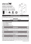
Owner's Manual
".
|
=*=
Generator
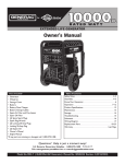
Wheel kit
Safety Rules......................................
Know Your Generator ...............................
2-4
5
Storage Cover
Assembly ........................................
6-7
Battery
Operation ......................................
Product Specifications ..............................
Maintenance ......................................
Battery Float Charger
Battery Charge Cables
Spare Spark Plug,Air Filter, and Oil Filter
Spark PlugWrench
(2) Locking 30 Amp Plugs
EngineOil
Owner's Manual
Engine Manual
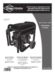
If any parts are missing or damaged,call 1-800-270-1408.
Questions?
Call:Generac
8-13
14
14
Storage ..........................................
15
Troubleshooting ...................................
Schematic ........................................
15
16
Wiring Diagram ...................................
Replacement Parts ..............................
Notes ...........................................
17
18-22
23
Warranty ...................................
Help is just a moment
Generator Helpline - 1-800-270-1408
Web: www.generac-por tables.corn
away!
M-F 8-5 CT
Last Page
SAFETY
EQUIPMENT
DESCRIPTION
_IL
_Read familiarthlswith
manual
become
your carefully
generator. andKnow
its
applications, its limitations and any hazards
involved,
The generators are an engine_riven,
revolvTng field,
al:ernatTng current (AC) generator, It wzs designed _o
supply electrical power for operating compatible electrical
lighting, appliances, _ools and motor loads.The generator's
revolvTng field is drTven at about 3,600 rpm by a singlecylTnder engTne.
CAUTION!
DO NOT exceed the generator's
wa_age/amperage c_pacfty. See ==Don't Overload
Genera_or" on page 13.
hls is
thetosafety
alert personal
symbol. injury
It is used
to
alert
you
potential
hazards.
Obey all safety messages that follow this
symbol to avoid possible injury or death.
The safety alert symbol (_)
The Emission Control System for this generator is
warranted for standards set by the Environmental
Pro_ecUon Agency. For warranty information refer to the
engine owner's manual.
!_ _h_ Sta_e of Californ! a a spzr_ zr_ster is _qu!_ d bylaw
(Sec:io_ 4_t2 of;he C_lifomi_ Public Resou_es Code).
Other S_es m_ _ave Sim!lar I_S. Fecle_l lawsZpply on
fede_l IzndSi IfYO_ e_ip 1;hem_ffler _i_h Z spare arres_ r,
is used with a signal word
(DANGER, CAUTION,WARNING),
a pictorial and/or a
safety message _o aler_ you _o hzzards. DANGER
indicates
a hzzard which, if not avoided, vAf!result in death or serious
injury.WARNING
indicates a hazard which, if n_t avoided,
could result in death or serious iniury. CAUTION
indicates a hzzard which, if not avoided, might result in
minor or moderate injury. CAUTION,
when used
without the aler_ symbol, indicates a situation that could
result in equipment damage. Follow sat'e_ messzges to
avoid or reduce the risk of iniury or de_th.
Every effor_ has been made _o ensure that fnforma_ion in
_his manual fs accurate and current, However, we reserve
the right to change, al_er or otherwfse improve the product
and thfs document at any tfme wfthout prfor no_ice.
RULES
WARNING
The engine exhaust from (;his produc_ contains
chemicals known to the State of Callfornla to cause
cancer, birth defects, or o_her reproductive
harm,
Hazard
Symbols
Electrocu_Jon
Toxic Fumes
Explosive Pressure
and
Meanings
Electrical Shock
E_plesfen
Chemical Burn
Electrical Shocl(
Fire
Hot Surface
DANGER
WHEN
,Turn
ADDING
g¢:n¢:rat.or OFF and let ic cool _t least _-min_os
n_rn0vIng
,DO
DANGER
,Keep
FUEL
gas taPi Lo_en
caP slowfi co mJieve PreSSUre in _n Ic
NOT overfitl
_n_AI!ow apacefor
furl away fr°m
aparksi open
fl_mes,pi!oc
I!ghtsi hear. and
,when using
_enerator
for
backup
powen
,_i_0t(!i_
,This
, use a ground Circuit fault interrup_
(G FCI) in any damp or
highly
conductive area_ such _s rnc'ta! d0tl_ng or s_¢l wet I_
generator is not for usein mobile equipment
WHEN
TRANSPORTING
,
Transpo_repair
,
Disconnec_
OR
with rue! tank
REPAIRI
EH_
0r m_.rin_
NG EQUIPMENT
or wi_h rue! shut_
No- useg_n_r_r_th _let_ieal_o_swhich
a_ worn
WHEN
apark plug wire:
STORING
FUEL
OR EQUIPMENT
WITH
FUEL
NOT h_.ndle generac0r or _!ettriea! COrds Whi!_ standing
in water, While bar_o0t_ 0n while hands Or"fec-_
"DO
N_
a!!0w unqualified Persons or chi!dren _O OPerate or
DANGER
dryers
or Other appliantes that h_ve pilot ligh_or Other
ignition
souse _¢_uso thc_ican i_nitefuelvapo_
_WARNING
,This
generator does not
33CFR=!83
,
F_.ilur'__
genera_t,
,Wc_r
protettiye goF_!esirubberapron_ and rubber g!oves.
meet U.S.C_st
Gua_
Regu]ad0n
_nd should not b_ used on marine _pplit_tions
USe=he, _.ppropri,_te OiSi GO_t
could _osult in bodily
inju_
Guard
_nd/or prope_
CAUTION
'Se_!'D0n!t
Over!oad G_n_rac0 r'' on page 13.
, $_.rt generator and le_._ngine scabflfzebefor_ ¢0nne_ing
_l_ric_l I_dSi
! c0nn_=_I_C_I JOadS
!nOFFpOS.sO,_
_he,_
_umONfo_
Opera'don.
, "-urn d_ccr!_l loads OFI: and d!sc0nn_¢cfrom generacor
CAUTION
' USe gen_racOronly for incend_cluses.
' li_U h_-ve
qUe_'c(ons
_-bOUC
incendedU_ei
askd_io_ 0 r C_-i
I
,Al!ow
eClurpm_ntto ¢ool befo_ _ouching
CAUTION
,DO
NOT expose g_ner_tor tO exCeS$(WmoiscU_i dust.dirt:_
' DO NOT inser__.n_Obj_ct_through €oolingsio_i
, i_¢0nnc_t.oddcv(cesoverhc_ti_um _h_m Off_nd disc0nnec_
, Shut c_ _n_ra_ot" if:
_l_ri_!
0utpu_ is lost;
-un(€vibrat_s _Cossivoly.
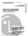
KNOW
YOUR
Read this owner's
manual
G EN ERATOR
and safeb/rules
before
operating
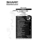
Compare the illustratTons wi_h your genera_or, to familiarize
adjustments. S_¢e this manual for future reference.
your genera_or,
yourself wT_ the Io_ions
of various controls and
CTrcuit Breakers (AC)
FuelTank
12Volt DC
Receptacle
Choke Lever
120/240Volt AC,
30 Amp Locldng
Receptacle
rl_Arres_er M_ffler
120Volt AC, 30 Amp
Locl_TngReceptacle
120/240Volt AC,
50 Amp Receptacle
120Volt AC, 20 Amp
Duplex Recep_cle
GroundingF_stener
12Volt DC ReceptaCle
LJse :his _ceP_€!e W!_h
bat_e_ Charge cables _ Charge a l2Vo!t b_ery,
Am
Ou exRete
t=ucle_M
be
i20V°lt
AC' 20
P
P
P
i
_Y
..........
i 20 volt ACi Single ph_e, 60 HZ eiectri_l lighti_gi Epplia_¢e,
Ch0_
Leve r _ Used whe_ staring a c01d e_gi_e i
CirCUit Breake_
(AC)Each
receptacle is provided
wth_
ush_orese_
clrcul_bre_k_r_oprotectd_
......... P: .... _
...... ": 0ver d_d ........
........... :
gener_r" zga!_S: e!e_r!_
....
:.............
FUel Tank _ CapaCity Of Seven (7)UiSi gaii0_S.
20VoitAC
........... n_ Fastener
i
, 30Am [p Lockin
Ground
usedtosuppyelectrica
ower for the epera_Jon of .........
,...... : "
,.
20VotAC
30Amp, sngle phase bu.z
elec_rica_ I=g_ti g,....... _avi_ :UrSd ct0_
_
......................
:...........
:
If reci_fred
p!ease consul_
a
I....
_ ..... :
........... : ......................
:..............
............
! 20!240 Volt ACi 30 Amp I-ocldng Receptac!e
be used _ suppl_ e!ec_ic_l Power fop _he
20 _ndt0r 240Vo_AC
30Amp S _gle:ph_e 60Hz
eiec_H_i lighting;appliance, t001Z_d m_;0ri0adsi
_ ay
S0 Amp, s nge phase,_O Hz e ec_r cal loads
Am Cleaner
pre c e_er to
into d_e enginei
Uses a dry O/pe fTiter:element and lea m
at _brm_l (_igh)Speeds When the_ is _ i0_d p_Se_ _nd
the engine at idle _I0W)Speeds whe_a 10ad i_ not
Lrese_
.......................
:...........
F
Run/S_op Switch -- _st
be in "Run" posiUon to sta_
engTne, Sette Stop tostoparunnmge_g
! e
EXhauSt muffler 10wets engine
_oise _d is _Uipped Wi_h Z spzrP.Zrrester
ASSEMBLY
Install Wheel
Your generator requires some assembly and is ready for
use at_er it has been properly serviced with the
recommended oil and fuel.
Kit
The wheel Idt is designed to greatly improve the por_bili_
of your generator.
NOTE:Wheel
kit is not intended for over-the-road use.
You will need a socket wrench with I/2" or 13ram socl(ets
If you have any problems with the assembly of your
generator, please call the generator
helpllne at
1-800-270-1408.
and a needle-nose plier to instil
IMPORTANT:Any
a_empt to run the unit before it hzs
been serviced with the recommended oil will result in an
I.
Place the bo_om of the generator cradle on a flat,
even surface.Temporarily
place unit on bloc_ to e_se
assembly.
2.
Slide zxle through both axle mounting
cradle frame, as shown in Figure I.
Slide a wheel over the axle.
Refer to Figure
engine failure.
Remove
Generator
From
Carton
3.
I,
Set _rton on a rigid flat surface with "This Side Up"
arrows pointing upward.
2.
Carefully open top flaps of shipping car_on. Review
"Cold Weather
Operation"
on pzge 10.
3.
Cut down corners at one end of _rton from top to
bo_om and lay that side of _rton down tla=
4.
Remove all pacl(Tngmaterial, car_on fillers, etc.
S.
Remove the generator
NOTE:
vv
I and install the wheel
kit as follows:
brackets on
Be sure to install both wheels with the air
pressure valve on the outboard side.
4.
Place the e-ring onto the groove in the axle.You may
add the flat washer if desired.
NOTE: Use retaining pins instead of e-clip, if appli_ble.
5. Place one end of the needle nose pliers on the bot_m
of the axle and the other end of the pliers on top of
the e-ring. Seat the e-ring by pressing the pliers closed.
from the shipping carton.
6.
II
this kit,
Repeat step 3 through 5 to secure second wheel.
30ram capscrews, washers and lock nuts,
BEFORE STARTING
ENGINE
With the wheels on, you can now Hft up the handle
end and a_ch tie suppor_ leg wTth 20ram cap screws
and lock nuts.
Add Engine Oil and Fuel
7. Remove
tie
8.
9,
_emporary
blocks.
At_ch the vibration mourns to the support leg with
IO, Check tiatallfasteners
areright
znd thetires
are Tnfla_d
_o tile value marked on tile tTre or wTthin IS and 40 psT.
Check
Battery
/Attach
Negative
Battery Wire
THE
• Place generator on a level surface.
• Refer to engfne owner's manual and follow ofl and fuel
recommendations
and instructions,
CAUTION
The sealed battery on the generator is fully charged and
pre-Tns_lled except for the negative (blacl_) battery cable,
To install;
I.
Cut off _ie wrap securing loose end of negative (black)
c_ble.
2,
Remove nut and washer on negative bakery terminal,
3,
Slide negative battery cable over screw on negative
_erminal (Figure 2),
NOTE: Checl_ oil often during engine break-in, Refer to
engine owner's manual for recommendations,
NOTE: The generator zssembly rotates on a prelubricated
and sealed ball bearing that recIuires no additional
lubrication for the life of tie bearing,
Negative
battery
c_ble
\_
Screw
Positive battery cable
_t.
Re_ch
wzsher and nut and tighten,
5.
Verify tiat connections to bakery and generator are
_Jght and secure,
USING
System
THE
GENERATOR
How to Use the Battery
Ground
The generator has a system ground :hat connects the
generator frame components _o the ground terminals on
the AC output recep_cles.The system ground is connected
_o the AC neutral wire (see "EquTpment DescrTpdon",
earlier in thTs manual).
Special
Charger
Use bakery float charger iack to I_s_ep:he sr_r_ing battery
charged and ready for use. B_t_ery charging should be done
in a dry Ioc_ion, such as inside a g_rage.
• Plug the charger into the unit's "Battery Float Charger"
jack, which is located on the s_rter switch (Figure 3).
Plug ba:tery charger into a 120VoltAC wall recep_cle.
Requirements
There may be Federal or $_te OccupatTonal Safety and
Health AdmTnTstratTon(OSHA) regulations, local codes, or
ordinances that apply _o the in_ended use of the generator.
Please consult a qualifTedelectrician, electrical inspector, or
the local zgency having jurisdiction.
\\
• Unplug :he charger from :he unit and the wall ouder when
generator is being s_r_ed and while it is in operation.
• In some areas, generators are required to be registered
with local utili_/companies.
• It'the generator is used at a construction site, there may
be additional regulations which must be observed.
• Keep this charger plugged in when generator is not in
use to prolong battery life.The charger has a built in float
ecIualizer and will not overcharge the b_tery, even when
plugged in for an ex_ended period of time.
Connecting
System
IN PORTANT:
See "B_ery
additional information.
to a Building's
Electrical
Connections for s_ndby power to a building's electrical
system must be made by a qualified electrician.The
connection must isolate the generator power from u_ility
power, and must comply with all applicable laws and
electrical codes.
DANGER
Maintenance"
on pzge 14 for
OPERATING
THE
G EN ERATO R
IN PORTANT:
Always unplug the battery float charger
before star_ing :he generator.
CAUTION
,wh_, usi,g_o,o_tor_orbackup
p0*o_,
,_i_
S_
[DOnt _erlo_.d
GCner_t:or_on pa_¢ 3;
"S_
_ne_t:or _.nd!et__ngin_ s_bi!!ze_before €onn_ct:ing
electrical Ic_dSi
, Use a ground _UI_Circuit interrUp_ (G FCI) in anydamp or'
highly ¢0nducciye arca_suchRsmG_a!d_€l_ngor' s_¢l wor`I_
, C0nn_c__l_¢tr!cal !0ads !n OFF p0sitJon,rhen turn ON for`
, Turn oJf:ccr(_.lloads OFF and d(sconn_¢cfrom generator
N_ h_ndl_gcn_r_cOr`
Or'_!ec_rica!
cordsWhi!_s_nding
W_rer,
Whi]_b_oo_ Orwhileh_.nd_.
Or _ec_
N_
a!!owunqualified
_mons
or chi]d_nro op_
or
Starting
the
Engine
Stopping
the Engine
Disconnect all electrical loads from the generator, Use the
following s_r_ instruction steps by numerical order:
I,
Make sure unit is on a level sur_ce,
I.
Unplug all electrical loads from generator panel
recep_cles. NEVER star_ or stop engine with electrical
devices plugged in and turned on.
IMPORTANT=
Failure to star_ and operate unit on a level
sur_ce will c_use the unit not _o start or shut down during
operation.
2.
Put idle control switch in "OFF' position.
3.
Let engine run at no-load for 30 seconds _o stabilize
in_ernal _empera_uras of engine and generator.
2.
4.
Turn engine off"according to instructions
engine owner's manual.
S.
Move fuel valve to "OFF' position.
Turn the fuel valve to the "On" position (Figure 4).The
fuel valve handle should be vertical (pointing toward
_he ground) for fuel to flow.
Operating
Automatic
given in
Idle Control
This switch is designed to greedy improve fuel economy.
When this _wltch is turned
ON, the engine will only
run at i_s normal high governed engine speed when an
electrical load is connected,When an electrical load is
3.
Mal__esure the Idle Control
(Figure 5).
_m
switch is in "Off"
position
removed, the engine will run at a reduced speed. With
the
switch off, the engine will run at _he normal high engine
speed. Always have the switch off when starting
and
stopping the engine.
Charging a Battery
BI
Your generator has _he capability of recharging a discharged
12Volt automotive or utiliL-ystyle storage battery. DO
NOT use the unit _o charge am/6Volt batteries. DO NOT
use the unit _o crank an engine having a discharged battery.
IDLE
DANGER
4.
Start the engine according to instructions
engine owner's manual.
given in 1:he
NOTE: If engine starts after 3 pulls but f_ils to run, or if
unit shu_s down during opera_ion, mal_ sure unit is on a
level su_ace and check for proper oil level in crankcase.
This unit mm/be equipped wi_h a low oil protection device.
See engine manual.
Connecting
Electrical
Loads
• Let engine s_bilize and warm up for a few minu_es after
starting,
• Plug in and turn on the desired 120 and/or 240VoltAC,
single phase, 60 Hz electrical loads.
• DO NOT connect 240Volt
recep_cles.
• DO NOT
loads to the 120Volt
To recharge
connect 3-phase loads to the generator.
• DO NOT connect 50 Hz loads _o _he generator.
• DO NOT OVERLOADTHE
GENERATOR,
"Don't
Overload
Generator"
on page 13.
See
I.
12Volt
bat_rles,
proceed
as follows:
Check fluid level in all bat%ery cells. If necessary, add
ONLY distilled water to cover separators in battery
cells. DO NOT use tap wa_r.
2.
It"bakery TsequTppedwTth yen= caps, make sure =hey
are Jnsr_lled and are tTght.
Build a structure that will enclose three sides and the top
of the genera_0r.
3.
It"necessary, clean battery termTnals.
I.
4.
Connec= battery charge cable connec=or plug to panel
recep_cle identified by the words "I2-VO/TS D.C."
Make sure entire muffler-side of generator is exposed.
Note that your generator may appear different from
that shown fn Figure 7.
S.
Connect bat_ry charge cable clamp with red handle
_o the positive (+) battery terminal (Figure 6),
2.
Ensure a minimum of _wo feet clearance between open
side of box and nearest obiec=
Connect battery charge cable clamp with black handle
_o the negative (-) b_ery termTnal (Figure 6).
3.
Face exposed end away from wind and elements.
7.
Start engine, let engine run while bz_tery recharges.
4.
8.
When
Enclosure should hold enough heat created by
generator to prevent problems.
6.
battery has charged, shut down engine
NOTE: Use an amomod_
hydrometer _o _st battery s_a_e
of charge and condition. Follow the hydrometer
m_nofaztzrer's instrucUons care4ully.Gener_l_ a b_'_ery is
considered _o be at 100% state of charge when specific gr_Ly
of_ fluid (_ measured by hydrometer) is 1_260or higher.
COLD WEATH
OPERATION
DANGER
ER
Under cer!_in weather conditions(t_mperatures below
40OF[4=C] and a high dew point),your generator may
experience icing of the c_rburetor and/or the crankcase
breather system.
.Keep at:!eas t 2 "_ec_of clearance on al!sides Ofg_n_rator for
_d_qUateventilati0n.
, DO NOT Oper_e gen_r_or insidoaw buildingOrendc_i
!ncluding_ gene_r comparm_ c_z _rr._or_J v_icl_ _RV).
, P,_m0vegener_t0r
_romShelter
when _emperatureiSabove
_0 [ c] ..................................................................
RECEPTACLES
CAUTION
Use each recep_cle to operate 120%1=AC, single-phase,
60 Hz electrTcalloads requiring up to 2,400 wa_ (2.4 kVV)
a: 20Amps of curren:. Use cord se=sthat are ra:ed for
125Volt AC loads at 20 Amps (or grea=er).
120 Volt AC, 30 Amp Locking
Receptacle
Use a NEMA I-5-30 plug with this recep_cle, Connec: a
3-wira cord se: rated for 125VoltAC loads at 30 Amps to
the plug (Figure 10).
m
12 Volt DC,
I 0 Amp
Receptacle
ThTs receptacle _llows you to recharge _ 12%1=
automo:fve or utfliv/style storage battery wfth :he bakery
charge cables provided (Figure 8),
_BI
_e]mE_,_i_D]E_lm._mgm
3-Wire
Cord Se:
NEMA
L5-30
A Neu:ral
120V
Hot
Ground (Green)
ThTs receptacle can no= recharge 6Volt bakeries and can
no: be used to crank an e_gine h_ving a discharged bakery,
See the section "Charging a Batter)/' (page 9) before
a_empting to recharge a bakery,
120 Volt AC, 20 Amp,
Receptacle
Duplex
Eachreceptacle (Figure9) is protected agains: overload by
a 20 Amp push-to-reset cTrcui:breaker.
Use :hfs receptacle to opera:e 120 Volt AC, 60 Hz, single
phase loads requiring up to 3,600 wa_s (3,6 kW) of pov_er
a: 30 Amps,The outle: is protected by a 30 Amp
push-:o-reset
circui: breaker,
4.Wire
Cord Set
r
¥(Hot)
_
Y(Hot)
.............x (Ho_)
(Greem)
"['h!s recep_c!e powers 120/240 Vol_ AC; 60 Hz, singh
phase loads _uir!ng
up :o 3,600 w_'_s of pov_r at
30 Amps for! 20 Vo!ts; 7,200 watts of power (7;2 _
_1
30 Amps for 240 Vo!ts_The outle: !s protected by a 30 Amp
push-:o-reset
circuit: brewer.
120Volts
120Vol:s
W (Neutra!)
N EMAI
4-50
Use :his recepr_c!e _o opera:e !20_40Vo!:AC,
60 Hz,
single phase !o_ds requ!r!ng up to 7,500 watts (73 kW)of
power,The oudet !s prot.ec_;ed
by _ 35 Amp pusl_to-rese:
DON'T OVERLOAD
G EN ERATO R
You must mak_ sure your generator r._n supply enough
ra_ed (running) and surge (starring) watts for the items you
will power at the same time, Follow these simple steps:
I.
Select the items you will power at the same _ime,
2.
To_I the rated (running) watts of these items,This is
"the amount of power your generator must produce to
keep your i_ems running, See Figure 13.
Estimate how many surge (s_rting) wa_s you will
need, Surge wattage is the shor'; burst of power
needed to star_ electric motor-driven tools or
appliances such as a circular saw or refrigerator.
Because not all motors s_rt at die same time, total
surge watts can be estimated by adding only the
item(s) with die highest additional surge watts to die
_or_l rated w_tts from s_ep 2,
Example:
Rated {Running)
Tool orAppl(ance
_¢¢indow
har
Addi_onal
i800
800
500
500
500
75
3075 Total
RunningWatts
1800 Highest
Deep Freezer
T_lev(S{0n
I.i_ht (75 Watt)
To_l Rated (Running)Wa_s
= 3075
HighestAdditional SurgeWat_
= 1800
To_l Generator Output
= 4875
Required
Power Management
To prolong the life of your generator and at_ched devices,
it is important to take care when adding electrical loads to
your generator, There should be nothing connected to the
generator outlets before starting it's engine,The correct
and safe w_/to manage generator power is to sequentially
add loads as follows:
I.
With nothing connected to the generator, start the
engine zs described in this manual,
2.
Plug in and turn on the first load, preferably die largest
load you have,
,
Plug in and turn on the next load,
S.
Again, permit the generator
6.
Repe_t steps 4 and 5 for each additional
to stabilize.
load.
NEVER add more loads than die generator c_paciw.Tak_
special care to consider surge loads in generator capaci_/,
as described above,
Capacity
3.
4.
Permit the generator output to s_bilize (engine runs
smoothly and at_ched device operates properly,
LilmE[] _
E=]mri
Tool or Appliance
I_ted*
(Running)
Watts
AddiUonal
Surge
($r,_rUng)
Watts
Essentials
UghtBulb-75 wa_
Deep Freezer
Sump Pump
Refrigerator/Freezer
- I8 Cu. Ft.
Water Well Pump- I/3HP
He.ring/Cooling
Window AC - I0,000 BTU
Window Fan
Furnace F_nBlower - I/2 HP
Kitchen
I_icrowave Oven - 1000Watt
Coffee r'4aker
ElectricStove - StogieElement
HoC Plate
Famil_ Room
DVD/CD Player
Stereo Receiver
Color Television - 27"
Personal Computer w/IT' monitor
Other
SecuritySystem
AM/F_ Clock R_dio
75
500
800
800
1000
500
1200
1600
2000
1200
300
800
1800
600
1300
I000
IS00
IS00
2500
I00
I00
450
500
800
180
300
Gar_e Door Opener - I/2 HP
ElectricWater Heater - 40 Gallon
480
4000
DIYIJob Site
Quart:z Halogen Work Light
Airless Sprayer-I/3 HP
Reciprocating Saw
Electric Drill - I/2 HP
Circular S_w - 7 I/4"
I000
600
960
1000
1500
1200
960
1000
1500
l_it_r
1800
1800
1800
2000
2500
1800
2000
2500
Saw - 10"
Planer/Jo(nter- 6"
Table Saw/RadialArm S_w - I0"
Air Compressor - I-I/2 HP
*'vVat_ges listed are approximate
appliance for actual wattage.
520
only_ Check tool or
SPECIFICATIONS
MaxTmum Surge Watts
Generator
.................
13,500 watts
Continuous Wr_L-l:ageCap_ci_/ ............
Power F_c_or ................................
R_ted Maximum Con_TnuousAC
7,500 watts
1,0
Lo_d Current:
At 120Vol_s .........................
62,5 Amps
At 240 Vol_s .........................
31,2 Amps
Phase ..................................
R_ted Frequency .........................
Fuel Tank C_padty ....................
ShTppTngWeighc ..........................
I_hase
60 Hertz
7 U,S, gallons
240 Ibs,
GENERAL HAINTENANCE
RECOMMENDATIONS
is kept cle_n and properly stored, NEVER
damaged or defective genera(;or,
Engine
operate
Generator maintenance consis_ of keeping the unit clean
_nd dry, Operate _nd score _he unic in _ cle_n dry
environment where it will noc be exposed to excessive
dust, dirt, moisture or any corrosive vapors. Cooling air
slo_s in_he generator muse noC become clogged with snow,
leaves or _ny other foreign m_teri_l.
NOTE: DO NOT use • garden hose to cle_n generator.
Water can enter engine fuel system and c_use problems. In
_ddi_ion, if w_ter enters generator _hrough cooling _ir slots,
some of _he w_ter will be re_ined in voids _nd crec_ of
_he rotor and sta_or winding insul_ion,W_er
_nd dir_
buildup on the generecor internal windings will eventually
decrease the insulation resistance of these windings,
Battery
The Owner/Operecor
is responsTble for makTng sure _h_t
_11perTodTcmaTncenance tasks are completed on _ cTmely
b_Ts; chic all dTscrep_ncies are corrected; _nd that the uniC
a
Maintenance
See engine owner's manual for instructions,
Maintenance
Maintenance
O_her _h_n float charging, described elsewhere, no
maintenance is recIuired for the b_t_ery, Keep the battery
_nd terminals cle_n _nd dry,
IMPORTANT:
B_ery charging should be performed in a
dry Ioc_cion, such as inside _ garzge.
To Clean
the Generator
• Use • damp clod_ to wipe exterior
surfaces clean.
CAUTION
CAUTION
• Use • soft brisde brush to loosen c_ked on dir_ or oil.
• Use • vacuum cleaner to pick up loose dirt.
POLLUTE. CONSERVE RESOURCES,RETURN
USED OIL TO COLLECTION CENTERS.
KEEPOUT OF REACH OF CHILDREN, DON'T
• Use low pressure _ir (not co exceed 25 psi) to blow
• w_y dir_, Inspect cooling _ir slots _nd opening on
generecor.These openings muse be kept cle_n and
unobstructed,
STO RAG E
Engine
The generator should be sr_r'ced at leas=once every seven
days and allowed =o run at leas=30 mTnu_es. If thTs c_nno=
be done and you must store the uni= for more than
30 days, use =he following guTdelinesto prepare i= for
Other
Storage
Tips
• To prevent gum from forming in fuel system or on
essential carbure=or parts, add fuel s_bilizer into fuel
_nk and fill wil:h fresh fuel. Run the uni= for several
storage.
Generator
Storage
See engine owner's manual forins=rucUons.
Storage
minu_es to circulate the addi=ive dlrough :he carburetor.
The unit and fuel can then be stored for up to
24 mondls. Fuel s_bilizer can be purchzsed locally.
• Clean the generator as outlined in "To Clean =he
Generator:'
• DO NOT s:ore fuel from one sezson =o ano=her unless
i= has been treated as described above.
• Check the= cooling aTr slots and openings on generator
are open and unobs=ructed.
• Replace fuel confiner
if it s_ri:s :o rust. Rus= and/or dir_
in fuel can cause problems
if i='s used wi=h :his uni=.
• Store unit in a clean and dry area.
, DO NOTp!aXe a St;orage
€owr 0¥_ Shot gener_cOr_
'
LeC_quipment c001 for a sufficienccim_ bc4ore placing
TROUBLESHOOTING
Problem
Cause
CorrectiOn
I,
but
engine
is
4.
C0_e_ed
device is badi
I
Shor_ circuit
load but 'bogs'i
when loads are connected,
2_
Generetor 'S
Enginewil!nots_=r_;or,
I
FuelValve is .....
nthe
I_n_ln_
_uns
ReS_ Cir_Ui_br_l_r.
_ooa
;el;
no
Engine shuts down during
operat On,
Eng!ne !acks power,
_,
in a conne_ed
load
See i'D0_;t Oyedoad Gene_z:or'i!
"Burn f ue
Off" pos=on.,
I
....
I,i,
r II TUe[ _ki
see 'iDonlt Qvert0_d Gene_r'i.
SCHEMATIC
1
2
PDWER
]2
1 i
22
PDWER
44
G
A
T
E
S
I
G
N
A
L
155
156
18
LOP
S_ITCH
IDLE
lib
WIRING
DIAGRAM
IOA
C_B_
AUTa RESET
IDLE
CDNTRDL
SWITCH
I
156
155
DC
FLOAT
EXPLODED
VIEW
- ALTERNATOR
900_
105
102.
21
\
52
57
\
54
39
64
46
29
25
45
_46
60
24
58
45 _4
6
1#
24
EXPLODED
VIEW
- FRAME
8
DETAIL OF
BAWERY TRAY
88
88
\
86
85
DETAIL OF ELECTRIC
START SWITCH
14
\
56
74
18
_97
86
/
85
_TO
STARTER
_TO
RBC
\,
TO + TERMINAL
ON BAKERY
DETAILOF JACK
ASSEMBLYCOAXIALDC
8O
9
PARTS LISTItem
I
2
3
4
5
6
7
8
9
10
II
12
14
IS
17
18
19
20
21
22
23
24
25
26
27
28
29
30
31
32
33
35
35
37
39
40
41
43
44
45
46
48
49
51
52
53
54
55
Part #
B 187024GS
194389GS
92982GS
92665GS
193823GS
84363GS
85000GS
93826GS
78831BGS
83465GS
77395GS
192980GS
B21S3GS
43116GS
73054GS
22127GS
77816GS
83083GS
86307GS
92247GS
M92531GS
189160GS
22129GS
82857GS
22531GS
92609GS
22142GS
A7433GS
B92731GS
90239GS
B 1342GS
96796GS
47481GS
B 1897AGS
40976GS
92532GS
66476GS
84355GS
194390GS
14353521GS
193646GS
81917GS
84986GS
56893GS
84132GS
67022GS
SRV56825DGS
23762GS
ALTERNATOR
Description
CRADLE
SHIELD, He_t.Tank
DECAL, Danger
INSULATION
ASSY,TanI_Fuel
CAP, with Gauge,Fuel
CLIP,Insulation
DECAL, Start Instructions
SCREW
GROMMET,Tank
NU-I, Lock
KIT,ValveTank
SCREW
SCREW
DECAL, FuelShut-Off
NUT
DECAL, Hot Muffler
SCREEN,SparkArrestor
SCREW
HOUSING, EngineAdapt_r
SUPPORT,Engine
NUT
WASH EI_ Lock
MOUNT, Vibration
SCREW
MOUNT, Vibration
SCREW
MUFFLER
SUPPORT,Engine&Muffler
GASKET, Muffler
ASSY,Rotor
WASHER
SCREW
ASSY,Starer
SCREW
BRACKET, Muffler
SCREW
ASSy,Centrol Panel (see page 21)
SHIELD, Heat
WIRE, Ground
KIT, Grounding Hardware
PIN, Roll
DECAL, Ground
SCREW
ASSY,Power Regulator
GROMMET, Rubber
CARRIER, Rear Bearing
WASHER
& FRAME
Item
57
58
59
60
62
63
54
66
74
77
78
79
80
81
82
83
84
85
86
87
88
90
97
98
99
100
101
102
103
900
Part #
66386GS
65849GS
B4871GS
74908GS
66849CGS
65795GS
66449LGS
22097GS
194034GS
189302BGS
77282GS
188987GS
188989GS
22287GS
22097GS
96113GS
192985GS
B4489GS
189302CGS
185939HGS
193347GS
58359GS
B193200GS
189718GS
B4135GS
22259GS
22129GS
49813GS
22125GS
NSP
Pars Not Illustrated
BB3O61GS
B4767GS
72347GS
189713GS
7311 IGS
84882GS
43438GS
70185GS
A8927GS
B4177GS
65787GS
37806GS
194033GS
Description
ASSY,Brush Holder
SCREW
COVER, BearingCarrier
SCREW
SCREW
RECTIFIER,Ba_ery Charge
BOLT, Starer
WASHER, Lock
KIT, Fold Down Handle Hardware
ASSy,Wire
SWITCH, Star_er
BRACKET, Swit=h
ASSY,JacI_DC
SCREW
WASHER, Lock
ASSY,Wire
TRAY,B_ery
BA'1-FERY
ASSY,Wire
ASSY,Wire
KIT, B_ery Hardware
LUG
ASS'(,Handle with Grip
GRIP
PIN, widl Lanyard
NUT
WASHER, Lock
NUT
WASHER, Lock
ENGINE
BO'J-FLE,Oil
COVER, Storage
PLUG, Spark
MANUAL, Owner's
FILTER,Air
WRENCH, Spark Plug
PLUG, 120/240V,30/_ 4p
FILTER_Oil
MANUAL, Engine
CHARGER, B_ery Float
CABLE, Battery Charge
PLUG, 120V,3OA
KIT, Decals
OptlonalAccessorlesNotlncluded:
8A883GS
Cord Wrap
EXPLODED
VIEW
AND
PARTS LIST - CONTROL
PANEL
19
20
21
19
27
28
\
26
10
6
lO
14
11
12
17 18
7
8
Item
I
2
3
4
5
6
7
8
9
I0
II
12
13
14
Part #
BB4461GS
23897GS
49226GS
91526GS
82538GS
82881GS
B4262GS
90418GS
75207NGS
75207AGS
75207GS
23365GS
68868GS
43437GS
16
Description
PANEL, Control
WASHER
WASH ER, Lock:
SCREW
SWITCH, Idle Control
WASH ER, Loci<
OUTLET, 50A, 240"/
OUTLET, I 0A, 12VDC
BREAKER, Circuit
BREAKER, Circuit
BREAKER, Circuit
WASHER
OUTLET, 30A, 120"/Locking
OUTLET, 30A, 120V/240V Locking
Item
15
16
17
18
19
20
21
22
23
24
25
26
27
28
Parl; #
68759GS
43180GS
22264GS
51715GS
64526GS
83970GS
64525GS
87962GS
84335GS
84134GS
B92069GS
84028GS
43181GS
43182GS
Description
OUTLET, 20A, 120"/
WASHER
WASHER, Lock
NUT
SCREW
BOARD, System Cor,::rol
STANDOFF, Hex
BREAKER, Circuit, I0A (au_:o),
12"/
ASSY,Wfre H_rness
GROMMET, Rubber Connector
BOX, Comtrol P_nel
TRANSFORMER, Idle Control
SCREW
WASHER, Lock
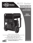
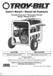
EXPLODED
VI EW AN D PARTS LIST - WH EEL KIT
16
5
14
3
i0
ii
4
9
8
Item
I
2
3
4
5
6
7
8
9
I0
II
12
13
14
15
16
17
Part #
BI93200GS
B4966GS
191267GGS
191265GS
39287GS
BI86927GS
191413GS
22413GS
52858GS
22247GS
39253GS
22145GS
49820GS
187104GS
189718GS
B4135GS
192432GS
Description
HANDLE (IncludesItem 15)
WHEEL
AXLE
E-RING
SCREW
LEG,Support
VIBE MOUNT, wTthW_sher
SCREW
NU-I, Lock
WASH ER
SCREW
WASHER
NUT, Nylok
WASHER, Nylon
GRIP
PIN, wTth Lanyard
NUT,Lock
NOTES
G
EN ERAC
PORTABLE
PRODUCTS
OWNERWARRANTy
LIMITED
POtable
POLICy
Effect;re
.lanUary
I i 2003
WARRANTY
TS I!Censed
t dema k OfBrT
PoWer
Br! S a
ower rodUc
_Pair 0r _placei tree 0f chargei any par_ or pa_ of:he e_Uipmen_ _hat am defective !n materia! or w0rkm_nship or b_hi
Transpo_tiOn
charges on parts submi_ed for repa!r Or replacement under this warranty mus_ be borne by purchaser.This
_rran_/is
effe_i_e for the time periods and subiect to the conditions provided for in _is poli_y. For _rra_ty
semite, find your
nea_S=A_th0rized
Se_!¢e dea!er by ca!!ing ! .800_270.1408iwar_n_
P_er
Products A_t_orized Service dealer.
THERE IS NO
OTHER EXPRESS WARRAN_
service may on!y be performed bya
IMPLIED WARRANTIES;
INCEUDING
Bri_s
&
THOSE OF MERCHANTABILI_
AND
FITNESS FORA PARTICULAR PURPOSE;ARE LIMITED TO THE TIME PERIOD SPECIFIED, OR TOTHE EXTENT PERHI_ED
By LAW, ANy AND A_ !HpL!EDWARRANT!ESARE
EXCLUDED, LIABILITY FOR CONSE_ENTIAL
DAMAGES UNDER
ANYAND
ALLWAR_NTIES
ARE EXCLUDED TO THE EXTENT EXCLUSION IS PERMI_ED
BY LAW. Some €0un=ries or
S_teS do not allow limitations o_ hOW long an imp!ied _rranv/!as_,
and some _o_nI:ries or states do not allow the exclusion
or limit=ion of inddent_[ or c0nsec_e_tial damagesi s0 the above limitation a_d excl_si0_ m_y r_0_apply to y0_This _rran_
gives YO_ specitlc !egaI rights and you m_/also have O=her righ=s t_at vary fr°m €_nt_
=o CO_nt_ 0r sr_
WARP_,N_
Equipment
P0r_ble
.................................................
I................
Gene_:0r
J
Consumer
Use ...............
!Year
2Years (2nd
I................
Commercial
I
J
Use ...............
90
I Year
The warrant,/period
begins On _:_e dal:e 0f pu_h_e by the first retail €onsumer or commercial e_d user, and Continues for the
period of =ime sta_ed i_ the table above. !'C0_sumer use!' means personal r_side_ial ho_seh01d Use by ,_ re=a. €0ns_mer,
i_0mme_ia!
_se'i means all 0t_er _sesi !nc!uding _se for c0mme_ia!i income P_d_cing 0r r_n_l purp0sesi once equipment has
bee_ _Sed c0mm_!a!!y,
i_ Shall _fter
be ConSidered _0 be in ¢0mme_ia! _se for purposes of;hiS _rr_n_.
_T_e
e_gi_e _nd Starting bakeries are warranted S01e]yby_e
WARRANTY
REGISTRATION
IS NOT
NECESSARY'TO
manufacturers
OBTAIN
o_ _h0se
WARRANTY
ON
BRIGGS
8= STRATTON
POWER
PRODUCTS
EQUIPMENT.
SAVEYOUR
PROOF: OF PURCHASE
RECEIPT. !F:YOU DO NOT PROVIDE
PROOF: OF THE INITIAL
PURCHASE
DATE ATTHE
TIH E WARRANTY
SERVICE !S REQUESTED,
THE
MANUFACTURING
DATE OFTHE
EQUIPMENT
W!LL BE USED TO DETERMINE
TN E WARRANTY
PERIOD.
About; you_ eq uiprnent; war_anL-_: .....................................................................................................................................
We welc0me warranv/repair and apo!ogize to you for being !nconvenienced.A_ Author!zed service dealer may perform warranty
repairsi Most warra_
repairs
hand!ed _inely,
but sometimes reques_ for _rran_
se_ice may _o_ be app_pria_ei For
examplei warra_
service w_uJd _
apply if equipment damage occurred because of misuse, lacl< of _ine
main_ancei
Shippi_&
handlingi_h0us!ng
0r imP_Per ins_!lat!0n, similarly, t_e _rran_
!s void !fthe man_cturing
d_e or _e Seria! _umbe _On _he
equipment h_s bee_ removed or _he eq_!pmen_ has been _lte_d or mod!fledi D_r!_g the _rr_n_y
period, the Authorize d Service
dealer, at i_s 0p_i0_;will repair 0r replace any p_rt =_a_,Up0_ ex_min_ti0_, iS fo_d _0 be defective Under normal use _nd Service.
Th!s warranv/wi!! _o; cover fo!]Ow!_g
,Normal
perform
•
Wea_:
wel!iThis
0_td00r
power e_!pmen_
like a!l mechan!cal deviceS; needs periodic
par_; se_!¢e and _placement
to
warranty does _ot cover repair when _ormal _se h_ exhausted the life of a part or the equipme_ti
Installation and Ha!n_enance:
Th!s warra_
dees no_ apply _ e(tu!pment or parts tha; have bee_ s_bje_ed _ improper or
unauthorized i_Sta!lati0n or a!;erati0n a_d modifi_tio_,
misuse, _eg!igence, accident, overloading, ove_peeding, imp_per
maintenance, repair or storage so asii_ o_r judgme_r_ to adversely affec_ its pe_rma_ce
and reliability, This w_rrar_ty ale0 does
no_ COver _0rm_l m_in_e_nce S_€_ _S ,_djus_me_tsif_el System €lea_i_g a_d 0bs=ruc=i0n (d_e =0 Chemical; dir_, c_rbOn or limei
Other Exdus!0ns: AIs0 excluded from th!s warranty are wea r Ttemss_€h _s q_ck C0uplers_ o!! @_gesi bel_si o-r!_gsi filters,
pump pack!_g;er=ii p_mps _hich have been run with0u_ _ter
Supplied 0r damage 0r ma!fun_i0ns _su_ng f_m _ccidents,
ab_Se, m0dif!_ti0nS; a!_rations; 0r imp_er
Se_i_ing 0r freea!ng or Chem!cal de_r!0_uoniAccess0ry
par_ Such aS gun_,
hoses_wands and nozzles are excluded from the product _rranty.A]so
_c]uded !s used, reconditio_ed, and demons=ra=io_
equipme_; equipme_ used for prime power i_ place of _ility power a_d e_ipmen_ _sed in life SUppOrt
STRATTON
POWER
PRODUCTS
JEFF ERSON ,WISCONSIN,
U.S.A.
GROUP,
LLC