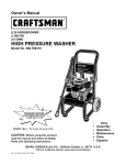
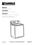
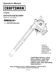
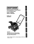
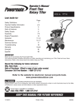
1
Owner's Manual / Manual del Propietario
Portable Generator 1 Generador Portatil
Model 1 Modelo 0 19 19- 1
CAUTION
%
Before using this product, read this manual and follow all
Safety Rules and Operating Instructions.
PRECAUCION
Antes de utilizar el producto, lea este manual y siga todas las
Reglas de Seguridad e lnstrucciones de Uso.
Questions? Preguntas?
Helpline
1-888-6 1 1-6708 M-F 8-5 CT
-
Troy-Bil*
is a registered trademark ofTroy-Bilt, LLC and is used under license t o Briggs & Stratton Power Products.
Troy-BiltB es una marca registrada de Troy-Bilt, LLC y se usa abajo licencia a Briggs & Stratton Power Products.
0
)I11111~1111111(
24847 12145
2
BRIGGS & STRATTON P O W E R PRODUCTS GROUP, LLC
JEFFERSON,WISCONSIN, U.S.A.
Printed in USA
Manual No. 197 126GS Revision 1 (06/20/2005)
Safety Rules
U
SAVE THESE I N S T R U C T I O N S
TABLE OF C O N T E N T S
Safety Rules. . . . . . . . . . . . . . . . . . . . . . . . . . . . . . . . . . ..2-4
Know Your Generator. ........................... .5
Assembly. .....................................6-7
Operation. . . . . . . . . . . . . . . . . . . . . . . . . . . . . . . . . . .. 8 - 1 I
Maintenance.................................... 12
Storage ........................................ 13
Troubleshooting.. ............................... 14
Warranty ...................................... 15
EQUIPMENT
DESCRIPTION
Read this manual carefully and become
familiar with your generator. Know its
its limitationsand any hazards
involved.
This manual describes an engine-driven, revolving field,
alternating current (AC) generator designed t o supply
electrical power for operating compatible electrical lighting,
appliances, tools and motor loads.The generator's revolving
field is driven at about 3,600 rpm by a single-cylinder
engine.
CAUTION! D O NOT exceed the generator's
wattagelamperage capacity. See "Don't Overload
Generator".
Every effort has been made t o ensure that information in
this manual is accurate and current. However, we reserve
the right t o change, alter o r otherwise improve the product
and this document at any time without prior notice.
The Emission Control System for this generator is
warranted for standards set by the Environmental
Protection Agency. For warranty information refer t o the
engine owner's manual.
SAFETY RULES
This is the safety alert symbol. It is used to
alert you to potential personal injury hazards.
Obey all safety messages that follow this
symbol to avoid possible injury or death.
(a)
The safety alert symbol
is used with,a signal word
(DANGER, CAUTION,WARNING), a pictorial and/or a
safety message t o alert you t o hazards. DANGER indicates
a hazard which, if not avoided, will result in death or serious
injury. WARNING indicates a hazard which, if not avoided,
could result in death or serious injury. C A U T I O N ,
indicates a hazard which, if not avoided, might result in
minor o r moderate injury. CAUTION, when used
without the alert symbol, indicates a situation that could
result in equipment damage. Follow safety messages t o
avoid or reduce the risk of'injury or death.
chemicals known to the State of California to cause
Hazard Symbols and Meanings
M%
I
4
Electrocution
Electrical Shocl<
&
Explosion
,
b+
Toxic Fumes
Copyright O 2005 Briggs & Stratton Power Products
Group, LLC. All rights reserved. N o part of this material
may be reproduced or transmitted in any form by any
means without the express written permission of Briggs &
Stratton Power Products Group, LLC.
Kickback
Fire
94
\$,)
>0\(<4( >>\>
Hot Surface
Section 1 : Safety Rules
Turn generator OFF and let it cool at least 2 minutes before
removing fuel cap. Loosen cap slowly t o relieve pressure in
Fill o r drain fuel tank outdoors.
D O N O T overfill tanl<.Allow space for fuel expansion.
Keep fuel away from sparks, open flames, pilot lights, heat, and
other ignition sources.
D O N O T light a cigarette o r smol<e.
W H E N STARTING EQUIPMENT
Ensure spark plug, muffler, fuel cap and air cleaner are in place.
D O N O T crank engine with spark plug removed.
If fuel spills, wait until it evaporates before starting engine.
Use a ground circuit fault interrupter (GFCI) in any damp o r
highly conductive area, such as metal decking o r steel work.
D O N O T touch bare wires o r receptacles.
D O N O T use generator with electrical cords which are worn,
frayed, bare or otherwise damaged.
D O N O T operate generator in the rain.
D O N O T handle generator o r electrical cords while standing
W H E N OPERATING EQUIPMENT
D o not tip engine o r equipment at angle which causes fuel t o
spill.
This generator is not for use in mobile equipment o r marine
applications.
W H E N TRANSPORTING OR REPAIRING
EQUIPMENT
Transportlrepair with fuel tank EMPTY o r with fuel shutoff
valve OFF.
Disconnect spark plug wire.
W H E N STORING FUEL O R EQUIPMENT W I T H FUEL
I N TANK
Store away from furnaces, stoves, water heaters, clothes
dryers o r other appliances that have pilot light o r other
ignition source because they can ignite fuel vapors.
A WARNING
When starting engine, pull cord slowly until resistance is felt
and then pull rapidly t o avoid kickback.
NEVER start o r stop engine with electrical devices plugged in
This generator does n o t meet U. S. Coast Guard Regulation
33CFR- 183 and should n o t be used o n marine applications.
Failure t o use the appropriate U. S. Coast Guard approved
generator could result in bodily injury andlor property
damage.
Section 1 : Safety Rules
A WARNING
I
A CAUTION
I
D O NOT tamper with governed speed. Generator supplies
correct rated frequency and voltage when running at governed
speed.
W H E N ADJUSTING OR MAKING REPAIRSTOYOUR
GENERATOR
Disconnect the spark plug wire from the spark plug and place
the wire where it cannot contact spark plug.
CAUTION
W H E N TESTING FOR ENGINE SPARK
Use approved spark plug tester.
D O NOT check for spark with spark plug removed.
I
A WARNING
I
See "Don't Overload Generator".
Start generator and let engine stabilize before connecting
electrical loads.
Connect electrical loads in OFF position, then turn O N for
operation.
Turn electrical loads OFF and disconnect from generator
- before stopping generator.
D O NOT touch hot surfaces.
Allow eauioment t o cool before touching.
1
'
Keep at least 3 feet of clearance on all sides of generator for,
adequate cooling, maintenance and servicing.
In the State of California a spark arrester is required by law
(Section 4442 of the California Public Resources Code). Other
states may have similar laws. Federal laws apply on federal
lands. If you equip the muffler with a spark arrester, it must be
maintained in effective working order.
I
I
I
CAUTION
Use generator only for intended uses.
If you have questions about intended use, ask dealer o r call
1-888-6 1 1-6708.
Operate generator only on level surfaces.
D O NOT expose generator t o excessive moisture, dust, dirt,
or corrosive vapors.
D O N O T insert any objects through cooling slots.
If connected devices overheat, turn them off and disconnect
them from generator.
Shut off generator if:
.-electrical output is lost;
-equipment sparks, smol<es, or emits flames;
-unit vibrates excessively.
1
\
I
I
I
K N O W Y O U R GENERATOR
Read this owner's manual and safety rules before operating y o u r generator.
Compare this illustration with your generator t o familiarize yourself with the locations of various controls and
adjustments. Save this manual for future reference.
/
I
I
1201240Volt AC,
Recoil Starter
(on engine shroud)
120 Volt AC, 20 Amp, Duplex Receptacles - May be
used t o supply electrical power for the operation of
12QVolt AC, 20 Amp, single phase, 60 Hz electrical, lighting,
appliance, tool and motor loads.
120/240VoltAC, 30 Amp Locking Receptacle - May
be used t o supply electrical power for the operation of
120 andlor 240Volt AC, 30 Amp, single phase, 60 Hz
electrical, lighting, appliance, tool and motor loads.
Air Cleaner - Protects engine by filtering dust and debris
out of intake air.
Choke Lever - Used when starting a cold engine.
Circuit Breakers (AC) - Push to reset circuit breakers are
provided t o protect the generator against electrical overload.
DataTag - Provides model, revision and serial number of
generator. Please have these readily available when calling
for assistance.
Fuel T a n k - Capacity of five (5) U.S. gallons.
Grounding Fastener - If required, please consult a
qualified electrician, electrical inspector, or local agency
having jurisdiction.
Oil Fill -Add
engine oil here.
Recoil s t a r t e r - Used to start the engine.
Rocker Switch - Set this switch t o "On" before using
recoil starter. Set switch t o "Off' t o switch off engine.
Spark Arrester Muffler - Exhaust muffler lowers
en@nenoise and is equipped with a spark arrester screen.
Assembly
ASSEMBLY
Install Wheel Kit
Your generator requires some assembly and is ready for
use after it has been properly serviced with the
recommended oil and fuel.
NOTE: Wheel kit is.not intended for over-the-road use.
You will need the following tools t o install these
components:
112" o r 13mm wrench
If you have any problems with the assembly of your
generator, please call the generator helpline at
1-888-6 1 1-6708.
Socket wrench with a 112" o r 13mm socket
Pliers
Remove Generator From Carton
Refer to Figure I and install the wheel kit as follows:
I. Tip generator so that engine end is up.
I.
Set the carton on a rigid flat surface.
2. Slide axle through both mounting brackets.
2.
Remove everything from carton except generator.
3.
Open carton completely by cutting each corner from
top t o bottom.
4.
Leave generator o n carton t o install wheel kit.
3.
Place a wheel on each side with air valve facing out.
4.
Place a washer on axle and then place an e-ring in axle
groove.
5. Install e-ring with pliers, squeezing from top of e-ring
t o bottom of axle.
6.
Hex N u t
-
.
Repeat step 3 through 5 t o secure second wheel.
Section 3: Assemblv
7.
Tip generator so that engine side is down.
Add Fuel
8.
Line up holes in support leg with holes in generator
frame.
9.
A t p c h support leg using t w o short (M8 x 16mm) cap
screws and t w o locking hex nuts.Tighten with a 112"
o'r 13mm socket and wrench.
NOTE: -rhis gasoline engine
is certified to operate on
gasoline. Exhaust Emission Control System: EM (Engine
Modifications).
10. O h support leg end of generator, slide handle onto
center of top of frame.
I I. Attach handle using t w o long (M8 x 45mm) cap screws
and t w o locking hex nuts.Tighten with a 112" o r 13mm
socket and wrench.
Turn generator OFF and let it cool at least 2 minutes before
removing fuel cap. Loosen cap slowly to relieve pressure in
12. Return generator t o normal operating position (resting
on wheels and support leg).
13. Check that tires are inflated t o value marked on tire
o r within 15 and 40 psi.
Fill fuel tank outdoors.
D O NOT overfill tank.Allow space for fuel expansion.
Keep fuel away from sparks, open flames, pilot lights, heat, and
other ignition sources.
D O NOT light a cigarette or smoke.
BEFORE STARTING T H E
, ENGINE
I. Use clean, fresh, regular UNLEADED fuel with a
minimum of 85 octane. D O N O T use fuel which
contains Methanol. D O N O T mix oil with fuel.
Add Engine Oil
Move generator t o a flat, level surface.
Refer t o engine owner's manual and follow oil
recommendations and instructions.
2.
Clean area around fuel fill cap, remove cap.
3.
Slowly add regular unleaded fuel t o fuel tank Be careful
not t o overfill.Allow about 1.5" o f tank space for fuel
I
I
CAUTION
*
I
expansion (Figure 2).
Refer to engine manual for 011fill information.
Damage to equipment resulting from failure to follow this
instruction will void warranty.
MOTE: Check oil often during engine break-in. Refer t o
engine owner's manual for recommendations.
NOTE: The generator assembly rotates on a prelubricated
and sealed ball bearing that requires n o additional
lubrication for the life of the bearing.
4.
Install fuel cap and wipe up any spilled fuel.
U S I N G T H E GENERATOR
Generator Location'
Generator Clearance
System Ground
The generator has a system ground that connects the
generator frame components t o the ground terminals on
the AC output receptacles.The system ground is connected
t o the A C neutral wire (see "Equipment Description",
earlier in this manual).
Special Requirements
There may be Federal o r State Occupational Safety and
Health Administration (OSHA) regulations, local codes, o r
ordinances that apply t o the intended use of the generator.
Please consult a qualified electrician, electrical inspector, o r
the local agency having jurisdiction.
In some areas, generators are required t o be registered
with local utility companies.
If the generator is used at a construction site, there may
be additional regulations which must be observed.
Connecting to a B~~~ilding's
Electrical
System
Connections for standby power t o a building's electrical
system must be made by a qualified electrician.The
connection must isolate the generator power from utility
power, and must comply with all applicable laws and
electrical codes.
highly conductive area, such as metal decking or steel work. .
DO NOT touch bare wires or receptacles.
DO NOT use generator with electrical cords which are worn,
frayed, bare or otherwise damaged.
DO NOT operate generator in the rain.
DO NOT handle generator or electrical cords while standing
in water, while barefoot, or while hands or feet are wet.
nqualified persons or children to operate or
The generator must be at least 5 ft. ( 1 52 cm) from
structures having combustible walls and/or other
combustible materials. Leave at least 3 ft. (92 cm) all around
generator including overhead, for adequate cooling,
maintenance and servicing.
Place generator in a well ventilated area, which will allow
for removal of deadly exhaust gas. D O N O T place
..kenerator where exhaust gas could accumulate and enter
inside o r be drawn into a potentially occupied building.
Ensure exhaust gas is kept away from any windows, doors,
ventilation intakes o r other openings that can allow exhaust
gas t o collect in a confined area (Figure 3). Prevailing winds
and air currents should be taken into consideration when
positioning generator.
Typical Generator Shown
Section 4: Operation
I
1
j
OPERATING T H E
GENERATOR
NOTE: If engine starts but fails t o run, o r if unit shuts
down during operation, make sure unit is on a level surface
and check for proper oil level in crankcase.This unit may be
equipped with a l o w oil protection device. See engine
manual.
electrical loads.
Connect electrical loads in OFF position, then t u r n O N f o r
Turn electrical loads OFF and disconnect from generator
Allow equipment t o cool before touching.
The generator must be at least 5 feet from structures having
combustible walls andlor other combustible materials.
Keep at least 3 feet o f clearance on all sides of generator f o r
adequate cooling, maintenance and servicing.
In the State o f California a spark arrester is required by law
(Section 4442 o f the California Public Resources Code). O t h e r
states may have similar laws. Federal laws apply o n federal
Starting the Engine
Disconnect all electrical loads from the generator. Use the
following start instructions:
I.
Make sure unit is on a level surface.
IMPORTANT: Failure t o start and operate unit on a level
surface will cause the unit n o t t o start o r shut down during
o~eration.
2. Turn red fuel valve t o "On" position (Figure 4).
Connectinn Electrical Loads
Let engine stabilize and warm up for a few minutes after
starting.
"
Plug in and turn on the desired 120 and/or 240 Volt AC,
single phase, 60 H z electrical loads.
D O N O T connect 240 Volt loads t o the 120 Volt duplex
receptacles.
D O N O T connect 3-phase loads t o the generator.
DO N O T connect 50 H z loads t o the generator.
3.
Start engine according t o instructions given in engine
owner's manual.
' Do
OVERLOAD
Overload Generator".
See
Stopping the Engine
I.
Unplug all electrical loads from generator panel
receptacles. NEVER start o r stop engine with electrical
devices plugged in and turned ON.
2. Let engine run at no-load for several minutes t o
stabilize internal temperatures o f engine and generator.
and then pull rapidly t o avoid I<icl<back.
NEVER start o r stop engine with electrical devices plugged in
3.
Turn engine off according t o engine owner's manual.
4.
Turn red fuel valve t o "Off' position.
Section 4: Operation
L
RECEPTACLES
overload the generator. See "Don't Overload
1201240Volt AC, 30 Amp, Locking
Receptacle
Use a NEMA L14-30 plug with this receptacle. Connect a
4-wire cord set rated for 250VoltAC loads at 30 Amps (or
greater) (Figure 5).You can use the same 4-wire cord if you
plan t o run a I2OVolt load.
Cord Set
Use each receptacle t o operate 120Volt AC, single-phase,
60 H z electrical loads requiring up t o 2,400 watts (2.4 kW)
at 20 Amps of current. Use cord sets that are rated for
125 Volt AC loads at 20. Amps (or greater).
GENERATOR ADAPTER
C O R D SET
The getierator is equipped with a 25' generator adapter cord
set designed for a 240Volt, 30Amp grounded neutral circuit
(Figure 7).The generator adapter.cord set provides a
convenient supply of emergency power into your dwelling
- so
that your generator can be operated safely outside.
I NEMA L 14-30
(Hot)
1
X (Hot)
T f / Ground (Green)
This receptacle powers I201240Volt AC, 60 Hz,single
phase loads requiring up t o 5,550 watts of power
(5.55 kW) at 23.1 Amps for I2OVolts o r 240Volts.The
outlet is protected by a push-to-reset circuit breaker.
120Volt AC, 20 Amp, Duplex
Receptacles
Each duplex receptacle (Figure 6) is protected against
overload by a push-to-reset circuit breaker.
The maximum load on each outlet is 2OAmps.The
maximum total load o n both yellow wire outlets or black
wire outlets is 30 Amps.
NOTE: Follow all safety precautions when connecting any
extension cord o r device t o the generator.
Section 4: Operation
DON'T OVERLOAD
GENERATOR
4.
5.
6. Repeat steps 4 and 5 for each additional load.
supply
--
Plug in and turn on the next load.
Again, permit the generator t o stabilize.
NEVER add more loads than the generator capacity.Take
special care t o consider surge loads in generator capacity,
as described above.
You must make sure yourgenerator can
enoughp
rated (running) and surge (starting) watts for the items you
will power at the same time. Follow these simple steps:
I. Select the items you will power at the same time.
2. Total the rated (running) watts of these items.This is
Tool or Appliance
the amount of power your generator must produce t o
keep your items running. See Figure 8.
3.
Estimate how many surge (starting) watts you will
need. Surge wattage is the short burst of power
needed t o start electric motor-driven tools o r
appliances such as a circular saw o r refrigerator.
Because not all motors start at the same time, total
surge watts can be estimated by adding only the
item(s) with the highest additional surge watts t o the
total rated watts from step 2.
Example:
Tool or Appliance
1
Window Air
Conditioner
1
Television
Light (75 Watts)
~~
~~
I
I
Rated (Running)
Watts
1200
500
75
3075 Total
Running Watts
I
1
Additional Surge
(Startind
w, W a t t s
1800
I
1
(
1800 Highest
Surge Watts
= 3075
= 1800
Total Generator Output Required = 4875
Total Rated (Running) Watts
Highest Additional Surge Watts
Power Management
To prolong the life of your generator andanached devices,
it is important t o take care when adding electrical loads t o
your generator.There should be nothing connected t o the
generator outlets before starting it's engine.The correct
and safe way t o manage generator power is t o sequentially
add loads as follows:
I. W i t h nothing connected t o the generator, start the
engine,as described in this manual.
2.
3.
Plug in and turn on the first load, preferably the largest
load you have.
Permit the, generator output t o stabilize (engine runs
smoothly and attached device operates properly.
Table SawIRadial Arm Saw - 10"
Air Compressor - 1-112 HP
1
2000
2500
1
1
2000
2500
"Wattages listed are approximate only. Check tool o r
appliance for actual wattage.
Maintenance
NOTE: D O N O T use a garden hose t o clean generator.
Water can enter engine fuel system and cause problems. In
addition, if water enters generator through cooling air slots,
some of the water will be retained in voids and cracks of
the rotor and stator winding insulation-Water and dirt
buildup on the generator internal windings will eventually
'decrease the insulation resistance of these windings.
SPECIFICATIONS
Starting Watts ........................ .8,550 watts
Wattage ............................ .5,550 watts
AC Load Current:
A t I20 Volts . . . . . . . . . . . . . . . . . . . . . . . . .46.2 Amps
A t 240 Volts . . . . . . . . . . . . . . . . . . . . . . . . .23.1 Amps
Phase .................................. I-phase
Rated Frequency. ....................... .60 Hertz
Fuel Tank Capacity. .................. . 5 U.S. gallons
Shipping Weight . . . . . . . . . . . . . . . . . . . . . . . . . . 169 Ibs.
Generator Cleaning "
Use a dam^ cloth t o w i ~ eexterior surfaces clean.
GENERAL MAINTENANCE
RECOMMENDATIONS
CAUTION
The Owner/Operator is responsible for making sure that
all periodic maintenance tasks are completed o n a timely
basis; that all discrepancies are corrected; and that the unit
is kept clean and properly stored. NEVER operate a
damaged or defective generator.
DO NOT expose generator to excessive moisture, dust, dirt,
or corrosive vapors.
DO NOT insert any, objects through cooling slots.
Use a soft bristle brush t o loosen caked on dirt o r oil.
Use a vacuum cleaner t o pick up loose dirt and debris.
Should you have questions about replacing components on
your Troy-Bil@ generator, please call 1-888-6 1 1-6708 for
assistance.
'
Ennine Maintenance
Data Tag
See engine owner's manual for instructions.
Data tag information is very important if you need help from
our Customer Service Department o r an authorized service
dealer.
A CAUTION
I*
Used motor oil has been shown to cause skin cancer in
certain laboratory animals.
Thoroughly
- . wash exposed areas with soap and water.
KEEP O U T OF REACH OF CHILDREN. D O N ' T
POLLUTE. CONSERVE RESOURCES. RETURN
USED O l L T O COLLECTION CENTERS.
;Use low pressure air (not t o exceed 25 psi) t o blow away
dirt. Inspect cooling air slots and opening on generator.
These openings must be kept clean and unobstructed.
II
I
The data tag (Figure 9) is located either on the heat shield
o r engine support on the muffler side of the generator.
For future reference, please copy the model, revision, and
serial number of the generator in the space below.
I I/
Copy Model
Number Here
Y
Generator Maintenance
Generator maintenance consists of keeping the unit clean
and dry. Operate and store the unit in a clean dry
environment where it will not be exposed t o excessive
dust, dirt, moisture o r any corrosive vapors. Cooling air
slots in the generator must not become clogged with snow,
leaves o r any other foreign material.
REV NO
Copy Revision
Here
Copy Serial
Number Here
Storage
STORAGE
+
Engine Storage
The generator should be started at least once every seven
days and allowed t o run at least 30 minutes. If this cannot
be done and you must store the unit for more than
30 days, use the following guidelines t o prepare it for
storage.
Generator Storage
Clean the generator as outlined in "Generator Cleaning".
Check that cooling air slots and openings on generator
are open and unobstructed.
See engine owner's manual for instructions.
Other Storage Tips
To prevent gum from forming in fuel system o r on
essential carburetor parts, add fuel stabilizer into fuel
tank and fill with fresh fuel. Run the unit for several
minutes t o circulate the additive through the carburetor.
The unit and fuel can then be stored for up t o
24 months. Fuel stabilizer can be purchased locally.
D O N O T store fuel from one season t o another unless
it has been treated as described above.
Replace fuel container if i t starts t o rust. Rust and/or dirt
in fuel can cause problems if it's used with this unit.
Store unit in a clean and dry area.
sufficient time before placing the
Troubleshooting
TROUBLESHOOTING
Problem
N o AC output is available,
but engine is running.
When loads are
connected, engine runs
good but bogs down.
Cause
Solution
I.
Circuit breaker is open.
I.
Reset circuit breaker.
2.
Poor connection o r defective cord set.
2.
Check and repair.
3.
Connected device is bad.
3.
Connect another device that is in
good condition.
4.
Fault in generator.
4.
Contact Authorized Service Facility.
I.
Short circuit in a connected load.
I.
Disconnect shorted electrical load.
2.
Generator is overloaded.
2.
See "Don't Overload Generator".
3.
Engine speed is t o o slow.
3.
Contact Authorized Service Facility.
4.
Shorted generator circuit.
4.
Contact Authorized Service Facility.
Engine shuts down during
operation.
O u t of gasoline.
Fill fuel tank.
Engine lacks power.
Load is t o o high.
See "Don't Overload Generator".
TROY-BILTB O W N E R WARRANTY POLICY Effective November 1,2004
LIMITED WARRANTY
"Troy-BiltB is a registered trademark of Troy-Bilt, LLC and is used under license t o B r i g s & Stratton Power Products. Brigs &
Stratton Power Products will repair o r replace, free of charge, any part, o r parts of the equipment*" that are defective in material
o r workmanship o r both.Transportation charges on parts submitted for repair o r replacement under this warranty must be
borne by purchaser.This warranty is effective for the time periods and subject t o the conditions provided for in this policy. For
warranty service, find your nearest Authorized service dealer by calling 1-888-6 1 1-6708. Warranty service may only be performed
by a Brigs & Stratton Power Products Authorized service dealer.
THERE IS N O OTHER EXPRESS WARRANTY. IMPLIED WARRANTIES, INCLUDING THOSE OF MERCHANTABILITYAND
FITNESS FORA PARTICULAR PURPOSE,ARE LIMITED T O THE TIME PERIOD SPECIFIED, O R T O THE EXTENT PERMITTED
BY LAW.ANY A N D ALL IMPLIED WARRANTIESARE EXCLUDED. LIABILITY FOR CONSEQUENTIAL DAMAGES UNDER
A N Y A N D ALL WARRANTIES ARE EXCLUDED T O THE EXTENT EXCLUSION IS PERMllTED BY LAW. Some countries o r
states do not allow limitations on how long an implied warranty lasts, and some countries o r states do not allow the exclusion or
limitation o f incidental o r consequential damages, so the above limitation and exclusion may not apply t o you.This warranty gives
you specific legal rights and you may also have other rights that vary from country t o country o r state t o state."
1
I
Equipment **
I
WARRANTY PERIOD*
Consumer Use
PressureWasher
1
l Year
Portable Generator
i
~ o m m e k c i aUse
l
1
2Years (2nd year parts only)
90 Days
l Year
*The warranty period begins on the date of purchase by the first retail consumer o r commercial end user, and continues f o r the
period of time stated in the table above. "Consumer use" means personal residential household use by a retail consumer.
"Commercial use" means all other uses, including use for commercial, income producing o r rental purposes. Once equipment has
been used commercially, it shall thereafter be considered t o be in commercial use for purposes of this warranty.
**The engine and starting batteries are warranted solely by the manufacturers o f those products.
I
I
i
i
WARRANTY REGISTRATION IS N W NECESSARYTOOBTAINWARRANTY ON BRIGGS & STRArrON POWER
PRODUCTS EQUIPMENTSAVEYOUR PROOF OF PURCHASE RECEIPT. IFYOU D O N O T PROVIDE PROOF OFTHE
INFTIAL PURCHASE DATEATTHETIMEWARRANTY SERVlCE IS REQUESTED,THE MANUFACTURING DATE OFTHE
EQUIPMENTWILL BE USEDTO DETERMINETHE WARRANTY PERIOD.
About your equipment warranty:
W e welcome warranty repair and apologize t o you for being inconvenienced.Any Authorized service dealer may perform warranty
repairs. Most warranty repairs are handled routinely, but sometimes requests for warranty service may not be appropriate. For
example, warranty service would not apply if equipment damage occurred because of misuse, lack of routine maintenance, shipping,
handling, warehousing o r improper installation. Similarly, the warranty is void if the manufacturing date o r the serial number on the
equipment has been removed o r the equipment has been altered o r modified. During the warranty period, the Authorized service
dealer, at its option, will repair o r replace any part that, upon examination, is found t o be defective under normal use and service.This
warranty will not cover following repairs and equipment:
ii:
Normal Wear: Outdoor power equipment, like all mechanical devices, needs periodic parts, service and replacement t o perform
well.This warranty does not cover repair when normal use has exhausted the life of a part o r the equipment.
I
Installation and Maintenance: This warranty does n o t apply t o equipment o r parts that have been subjected t o improper o r
unauthorized installation o r alteration and modification, misuse, negligence, accident, overloading, overspeeding, improper
maintenance, repair o r storage so as, in our judgment, t o adversely affect its performance and reliability.This warranty also does
not cover normal maintenance such as adjustments, fuel system cleaning and obstruction (due t o chemical, dirt, carbon o r lime,
etc.).
Other Exclusions: Also excluded from this warranty are wear items such as quick couplers, oil gauges, belts, o-rings, filters,
pump packing, etc., pumps which have been run without water supplied o r damage o r malfunctions;resulting from accidents,
abuse, modifications, alterations, o r improper servicing o r freezing o r chemical deterioration.Accessory parts such as guns,
hoses, wands and nozzles are excluded from .the product warranty.This warranty excludes failures due t o acts o f ' ~ o and
d other
force majeure events beyond the manufacturers control.Also excluded is used, reconditioned, and demonstration equipment;
equipment used for prime power in place of utility power and equipment used in life support applications.
I
/[
j ::
I
I;
BRIGGS & STRATTON POWER PRODUCTS GROUP, LLC
JEFFERSON,WISCONSIN, U.S.A.
I
@ Operating & Maintenance lnstructions
General Model Series noted on front cover are inclusive of the specific model number found on your engine.
alnstrucciones de Mantenimiento & Operacib
alnstructions d'utilisation et de maintenance
,
Los Modelos Serie Generales que aparecen registrados en la portada estan incluidos en el nlimero de modelo especifico encontrado en su motor.
La serie de Modeles notee sur la page de garde comprend le numero de Modele spbcifique qui se trouve sur votre moteur.
Engine - ~ o d e[Type
l
/Code
MOTOR- MODELOI TIPO I C~DIGO
M o d e l e /Type 1 C o d e - du m o t e u r
TABLE OF CONTENTS
Safety . . . . . . . . . . . . . . . . . . . . . . . . . . . 2-5
Engine Information . . . . . . . . . . . . . . . . . . . 6
Oil . . . . . . . . . . . . . . . . . . . . . . . . . . . . . .7-8
Fuel & Starting . . . . . . . . . . . . . . . . . . . . . . 8
Stopping.. . . . . . . . . . . . . . . . . . . . . . . . . .9
Maintenance.. . . . . . . . . . . . . . . . . . . . . 9-12
Adjustments . . . . . . . . . . . . . . . . . . . . . . . .13
Storage . . . . . . . . . . . . . . . . . . . . . . . . . ..I3
Emission Statement . . . . . . . . . . . . . . . 14-16
Warranty Information . . . . . . . . . . . . . . . 17-19
Parts & Service Information . . . . . . . . . . . ..20
Briggs & S t r a t t o n C o r p o r a t i o n
Milwaukee, W i s c o n s i n 53201
TABLA DE CONTENIDO
Seguridad . . . . . . . . . . . . . . . . . . . . . . . . . 2-5
Inforrnacion del Motor . . . . . . . . . . . . . . . . . 6
Aceite . . . . . . . . . . . . . . . . . . . . . . . . . . . 7-8
Combustible & Arranque . . . . . . . . . . . . . . . 8
Parada . . . . . . . . . . . . . . . . . . . . . . . . . . . . 9
Mantenimiento . . . . . . . . . . . . . . . . . . . . 9-12
Ajustes . . . . . . . . . . . . . . . . . . . . . . . . . . . . I 3
Bodegaje . . . . . . . . . . . . . . . . . . . . . . . . ..13
Declaracidn de Emisiones . . . . . . . . . . . 14-16
Informacidn de Garantia . . . . . . . . . . . . 17-19
Informaci6n de Partes & Servicio . . . . . . . . . 20
TABLE DES MATIERES
Securite . . . . . . : . . . . . . . . . . . . . . . . . . .2-5
Informations relatives au moteur . . . . . . . . . . 6
Sonde de niveau d'huile . . . . . . . . . . . . . . . 7-8
Carburant et demarrage . . . . . . . . . . . . . . . . 8
Arret . . . . . . . . . . . . . . . . . . . . . . . . . . . . . 9
Entretien . . . . . . . . . . . . . . . . . . . . . . . .9-12
Reglages . . . . . . . . . . . . . . . . . . . . . . . . . .13
Stockage . . . . . . . . . . . . . . . . . . . . . . . . . .13
Declaration relative aux Bmissions . . . . . 14-16
Informations relatives a la garantie . . . . . 17-19
Informations relatives aux pieces et au service
apres-vente . . . . . . . . . . . . . . . . . . . . . . . .20
O Copyright 2005 by Briggs & Stratton Corporation
o
24847 10059
4
I/
I
Safety Precautionc
a
@ Precauciones de Seguridad
1
BEFORE
OPERATING ENGINE
Read entire Operating & Maintenance Instruc-
;FEE,,,
* Briggs & Stratton does not necessarily know what
equipment this engine will power. For that reason, you
should carefully read and understand the operating
instructionsfor the equipment on which your engine is
placed.
THE OPERATING & MAINTENANCE
INSTRUCTIONS CONTAIN SAFETY
INFORMATION TO:
Make you aware of hazards associated with
engines
Inform you of the risk of injury associated with
those hazards, and
Tell you how to avoid or reduce the risk of injury.
A
The safety alert symbol is used to identify safety
information about hazards that can result in
personal injury.
A signal word (DANGER, WARNING, or CAUTION) is
used with the alert symbol to indicate the likelihood and
the potential severity of injury. In addition, a hazard
symbol may be used to represent the type of hazard.
A
A
A
DANGER indicates a hazard which, if not
avoided, will result in death or serious
injury.
WARNING indicates a hazard which, if not
avoided, could result in death or serious
injury.
CAUTION indicates a hazard which, if not
avoided, might result in minor or moderate
injury.
quevaa acoplar este motor. Por esta razbn, usted debe
leer cuidadosamente y comprender las instrucciones
de operacion para el equipo en el cual es colocado su
motor.
LAS INSTRUCCIONES DE
MANTENIMIENTO & OPERACION
CONTIENEN INFORMACION DE
SEGURIDAD PARA
Hacer que usted tome conciencia de 10s
peligros asociados con 10s motores
Informarlo a usted del riesgo de las heridas
asociado con aquellos peligros, y
Contarle como evitar o reducir el riesgo de una
herida.
I
Que vous preniez bien connaissance des
risques lies a I'utilisation de moteurs
Vous informer sur les blessures pouvant 6tre
causees par ces risques, et
Vous dire comment eviter ou reduire au
maximum les risques de blessures.
Le symbole d'alerte securite est utilisb pour
marquer les informations de securite sur les
risques pouvant entrainer des blessures sur
les personnes.
Un mot indicatif (DANGER, AVERTISSEMENT, ou ATTENTION) est utilise avec le symbole d'alerte pour
signaler la possibilite et la gravite potentielle d'une
blessure. De plus, un symbole de danger peut Qre utilise
pour indiquer le type de risque encouru.
El simbolo de aviso de seguridad es usado
para identificar informacibn de seguridad concerniente a 10s peligros que pueden producir
heridas personales.
Una palabra sefializada (PELIGRO, ADVERTENCIA o
PRECAUCION) es usada con el simbolo de aviso para
indicar la probabilidad de una herida y su gravedad
potencial. Ademas, un simbolo de peligro puede ser
utilizado para representar el tipo de peligro..
a
a
a
Lire entierement les instructions d'utilisation et
d'entretien ET les instructions de I'equipement
entraine par ce moteur."
U n manque de respect de ces instructions
peut entrainer des blessures graves ou m6me
mortelles.
Briggs & Stratton nlest pas necessairementau courant
de I'application pour laquelle ce moteur est utilise. Des
lors, nous vous recommandonsde lire altentivement le
mode d'emploi de IVquipement entraine par ce moteur.
LES INSTRUCTIONS D'UTILISATlON ET D'ENTRETIEN
CONTIENNENT DES INFORMATIONS DE SECURITE POUR
A
a
a
PELIGRO indica un peligro que si no es
evitado, ocasionarh la muerte o heridas
graves.
ADVERTENCIA indica un peligro que si no es
evitado, ocasionada la muerte o heridas
graves.
A
PRECAUCION indica un peligro que si no es
evitado, podria ocasionar heridas rnenores
o moderadas.
PRECAUCION, cuandoesusadosin el sirnbolo de aviso, indica una situacibn quepodria
ocasionar datios en el motor.
,,IIIIIIIIIIIIIII,
Toxic Fumes
Gases Toxicos
F u m C s toxiques
DANGER indique un risque qui, s'il n'est pas
elimine, entrainera la mort ou des blessures
tres graves.
AVERTISSEMENT indique un risque qui, s'il
n'est pas elimine, pourrait entrainer la mort
ou des blessures trbs graves.
ATTENTION indique un risque qui, s'il n'est pas
elimine, pourrait entrainer des blessures
mineures ou 16geres.
ATTENTION, lorsqu'il est utilise sans le symboled'aletie, indique une situation qui pourrait
causer un dommage au moteur.
danger et Ileur signification
jim bolos (de Peligro y Signific
Explosion
Explosi6n
Explosion
Partes en Movimiento
Pieces e n mouvement
*
* Briggs & Stratton no sabe IEcesariamenteque equipo
CAUTION, when used without the alert
symbol, indicates asituationthat could result
in damage to the engine.
Hazard Symbols iand Meani
DEMARRER LE MoTEuR
EL MOW,
Lea completamente las lnstrucciones de
Mantenimiento & Operacibn Y las instrucciones para el equipo acoplado a este motor.*
Dejar de seguir las instrucciones podria
ocasionar heridas graves o la muerte.
tions AND the instructions for the equipment
this engine powers.*
Failure to follow instructions could result in
serious injury or death.
Consignes de skurite
H o t Surface
Superficie Caliente
S u r f a c e tres c h a u d e
/&
(dd
Shock
Descarga El6ctr1ca
Choc
Kickback
Retour brutal
Safety Precautionn
The engine exhaust from this product contains
chemicals known to the State of California to cause
Drnmas
xiones de Seguridad
El gas de escape del motor que produce este
product0 contiene quimicos conocidos para el
Estado de California que ocasionan cancer,
defectos de nacimiento, u otros d a i o s
reproductivos.
A
CUANDO ANADA COMBUSTIBLE
APAGUE el motor y deje que se enfrie al menos
2 minutos antes de remover la tapa de gasolina.
Fill fuel tank outdoors or in well-ventilated area.
Do not overfill fuel tank. Filltank to approximately
1-112 inches below top of neck to allow for fuel
Uene el tanque de combustibleenexteriores o en
un Area bien ventilada.
No Ilene demas~adoel tanque de combustible.
Uene el tanque aproximadamente 1-112
pulgadas por debajo de la parte superior del
cuello para permitir la expansion del combustible.
Mantenga la gasolina a distancia de chispas,
llamas abiertas, lucespiloto, calor y otras fuentes
de encendido.
Compruebe con frecuencia si existen grietas o
fugas en 10s conductos de combustible, el
tanque, la tapa y en 10s accesorios. CAmbielossi
es necesario.
CUANDO DE ARRANQUE AL MOTOR
Make sure spark plug, muffler, fuel cap and air
cleaner are in place.
Do not crank engine with spark plug removed.
If fuel spills, wait until it evaporatesbefore starting
engine.
If engine floods, set choke to OPENIRUN
position, place throttle in FAST and crank until
engine stalls.
WHEN OPERATING EQUIPMENT
Do not tip engine or equipment at angle which
causes gasoline to spill.
Do not choke carburetor to stop engine.
WHEN TRANSPORTING EQUIPMENT
Transport with fuel tank EMPTY or with fuel
shut-off valve OFF.
WHEN STORING GASOLINE OR EQUIPMENT
WITH FUEL IN TANK
Store away from furnaces, stoves, water heaters
or other appliances that have pilot light or other
ignition source because they can ignite gasoline
vapors.
Les gaz dUchappement de ce moteur contiennent
des substances chimiques pouvant causer des
cancers, des malformations fetales ou d'autres
problemes de fkondation.
ADVERTENCIA
Turn engine OFF and let engine cool at least 2
minutes before removing gas cap.
Keep gasoline away from sparks, open flames,
pilot lights, heat, and other ignition sources.
Check fuel lines, tank, cap, andfittingsfrequently
for cracks or leaks. Replace if necessary.
WHEN STARTING ENGINE
'
Aseglirese que la bujia, el mofle, la tapa de
combustible y el filtro de aire esten en su lugar.
NO de arranque al motor si removib la bujia.
Si se derram6 combustible, espere hasta que se
haya evaporado antes de dar arranque al motor.
Si el motor se inunda, ajuste el estrangulador a la
posici6nOPENIRUN, coloque el acelerador en la
posici6n FASTy de arranque hastaque prendael
motor.
CUANDO OPERE EL EQUIP0
No incline el motor ni el equipo a un Bngulo el cual
pueda ocasionar derrames de gasolina.
No ahogue el carburador para detener el motor.
CUANDO TRANSPORTE EL EQUIP0
Transp6rtelo con el tanque de combustible
VAClO o con la valvula de cierre de combustible
en la posici6n OFF.
CUANDO ALMACENE GASOLINA 0 EL EQUIP0
CON COMBUSTIBLE EN ELTANQUE
Alrnacene a distancia de hornos, estufas,
calentadores de agua u otros aparatos que
utilicen luz piloto u otras fuentes de encendido ya
que estos pueden encender 10s vapores de
qasolina.
POUR FAIRE LE PLElN '
Couper le moteur et le laisser refroidir au moins
2 minutes avant d'ouvrir le bouchon du reservoir.
Remplir le rCervoir de carburant a I'exterieur ou
dans un local extrkmement bien ventile.
Ne pas trop remplir le reservoir. Laisser environ
4 cm sous le haut du col pour perrnettre la
dilatation du carburant.
Tenir I'essence A 1'8cart des Btincelles, des
flammes directes, des veilleuses, de la chaleur et
des autres sources d'btincelles.
'a Contrblerque les Durits, le reservoir,le cowercle
et les raccords de carburant ne presentent ni
fissures ni fuites. Remplacer si nkcessaire.
POUR DEMARRER LE MOTEUR
S'assurer que la bougie, le silencieux, le bouchon
du reservoir et le filtre a air sont bien en place.
Ne pas lancer le moteur quand la bougie est
retiree. .
Si du carburant a 616 renverse, attendre son
evaporation complete avant de demarrer le
moteur.
Si le moteur est noy6, placer le starter sur OPENI
RUN, amener I'acce16rateursur FASTet lancer le
moteur jusqu'a ce qu'il demarre.
LORS DE L'UTlLlSATlON DE L'EQUIPEMENT
Ne pas faire basculer le moteur ou I'bquipement
au-dela d'un angle qui provoquerait le renversement de I'essence.
Ne pas obstruer le carburateur pour arrkter le
moteur.
POUR TRANSPORTER L'EQUIPEMENT
Transporter avec le reservoir de carburant VIDE
ou avec le robinet de coupure du carburant en
position FERMEE.
POUR STOCKER DE L'ESSENCE OU L'EQUIPEMENT AVEC UN RESERVOIR PLElN
Les ranger loin des chaudieres, cuisinibres,
chauffe-eau, ou tout autre appareil comportant
une veilleuse ou susceptible de produire une
Btincelle,car ils pourraientenflammerlesvapeurs
d'essence.
-
.
-,
7
-
T*.--TmT,-,
Precauciones de Segl
Safety Precautio~
I
(
I
If there is natural or LP gas leakage in area, do not
start engine.
Do not use pressurized starting fluids because
vapors are flammable.
Start and run engine outdoors.
Do not start or run engine in enclosed area, even if
doors or windows are open.
(
I
I1
S'il y a une fuite de gaz nature1ou de GPLa proximite,
I
puertas o las ventanas
When starting engine, pull cord slowly until
resistance is felt, then pull rapidly.
Remove all external equipmentlengine loads
before starting engine.
Direct coupledequipment componentssuch as, but
not limited to, blades, impellors, pulleys, sprockets,
etc., must be securely attached.
A
I II
I
WARNING
I
Operate equipment with guards in place.
Keep hands and feet away from rotating parts.
Tie up long hair and remove jewelry.
Do not wear loose-fitting clothing, dangling
drawstrings or items that could become caught.
WARNING
these engines on All Terrain Vehicles (ATVs), funlrecreationalgo-karts, motor bikes,aircraftproductsor vehicles intendedfor use in competitiveevents. Useoftheseenginesin
such applications could result in property damage, serious
I I
II
a
Attacher les cheveux longs et retirer les bijoux.
Ne pas porter de vdtements amples, de ceintures
larges pendantes ou tout vdtement pouvant btre
ADVERTENCIA
Briggs&Strattonnoapruebaniautorizaelusodeestosmotoresen
VehiculosTodoTerreno(ATVs), carritos a motor con fines de
diversionlrecreaci6n, bicicletas motorizadas, productos para
la aviacibno en vehiculos que tengan comofin ser usados en
eventos competitivos. El uso de estos motores en tales aplicaciones podria ocasionar dafios a la propiedad, lesiones
graves (incluyendo paralisis), o incluso la muerte.
A
AllENTION
Briggs&Strattonn'approuvepasetn'autorisepasl'utilisationde
ces moteurssurlesvehiculestout-terrain, les kartsde loisirs,
les motoc clettes, les aeroplanesoulesvehiculesdestines a
itre utilisls en competition. Cutilisation de ces moteurs pour
ces applications peut entrainer des dommages materiels,
des lesions graves (y compris la paralysie) ou la mort.
--
W
Safety Precautions
Precauciones de Seguridad
*
l
. - -- --,-- - - - - -- -- --"onsignes de sd~-~-:"'
-?
Laisser le silencieux, le cylindre du moteur et les
ailettes refroidir avant de les toucher.
Retirerlesdebriscombustibles accumulesautourdu
silencieux et du cylindre.
Remove accumulated combustibles from muffler
area and cylinder area.
Install and maintain in working order a spark
arrester before using equipment on forest-covered, grass-covered, brush-covered unimproved
land. The state of Callornia requires this (Section
ga en orden de funcionamientoun
ntes de utllizar el equipo en una
Estado de California lo exige
Codigo de Recursos Pljblicos de
estados pueden tener leyes
DESREGLAGESOUDES
Disconnect spark plug wire and keep it away from
Desconecte el cable de la bujia y mantengalo a
Disconnect battery at negative terminal (only
engines with electric stalt).
Desconecte la bateria en la terminal negativa
(dnlcamentemotores con arranque el6ctrico).
WHEN TESTING FOR SPARK
CUANDO COMPRUEBE CHISPA
~
q
n
r
r
"
?
.
T
-
-S-
- v - T "
,-".me -m c*.
~formacionTecnica
Power Ratings
The power ratings for an individual engine model are
initially developed by starting with SAE (Society of
Automotive Engineers) code J1940 (Small Engine
Power & Torque Rating Procedure) (Revision2002-05).
Given both the wide array of products on which our
engines are placed, and the variety of environmental
issues applicable to operating the equipment, it may be
that the engine you have purchasedwill not develop the
rated horsepower when used in a piece of power
equipment (actual "on-site" power). This difference is
duetoavariety offactors including, but not limitedto, the
following: differences in altitude, temperature, barometric pressure, humidity, fuel, engine lubrication, maximum aoverned enaine weed, individual enaine to
engine"variability,design of'the particular piece dpower
equipment, the manner in which the engine isoperated,
engine run-in to reduce friction and clean out of
combustion chambers, adjustments to the valves and
carburetor, and other factors. The power ratings may
also be adjusted based on comparisons to other similar
engines utilized in similar applications, and will therefore
not necessarily match the values derived using the
foregoing codes.
Clasificacion de Potencia
La clasficacibn de potencia para un moddo de motor en
parbcular se desarrolla inicialmente comenzando con el d i g 0
J1940 de SAE (Sociedad de lngenieros Automotrices)
(Procedimiento de Clasiiicacibn de Potencia & Torque del
Motor Pequetio) (Revision 2002-05). Dado ambos un amplio
conjunto de productos en 10s cuales son puestos nuestros
motores, y la variedad de asuntos ambientales aplicables al
operar el equipo, puedequeel motor que usted haya comprado
no desarrolle la potencia nominal cuando sea usado en una
parte del equipo acoplado (potenda real "enel sitio"j. Esta
dierencia es debido a una variedad de, factores incluyendo,
oero no limitandose a, lo siauiente: diierencias en alMud.
iemperatura, presibn baromhrica, humedad, combustible;
lubricacibndel motor, mixima velocidad regulada del motor, el
motor particular a lavariabilidad del motor, disetio de la parle en
palticular del equipo acoplado, la rnaneraen la cual es operado
el motor, el despegue del motor para reducir la friccion y la
limpieza de las &maras de combusti6n, 10s ajustes a las
valvulas y al carburador, y otra variedad de factores. Esta
clasicaci6n de potencia puede tambien ser ajustada
basandose en comparaciones a aim motores semejantes
utilizados en aplicaciones similares, y por lo tanto no se
igualaran necesariamente 10s valores derivados usando 10s
codigos anteriores.
5
formations techniques
Puissance theorique
Cetalonnagede puissance d'un moteur est calcule au depatt
selon le code J1940 (Procaure de calcul de la puissance et
du couple des petits moteurs) (Revision 2002-05) de la SAE
(Society of Automotive Engineers). Compte tenu de la grande
varlete des machines ou nos moteurs sont utilisbs et du
nombre de problemes environnementaux applicables au
fonctionnement des huipements, il se peut que le moteur
que vous avez achete ne developpe pas la puissance
theorique une fois qu'il est monte dans tine machine
particuliere (puissance reelle sur site D). Cette difference
s'explique par un grand nombre de facteurs tels que les
suivants (liste non limitathe) : diffbrences d'altitude, de
temperature, de pression atmospherique, d'humidite, de
carburant, de lubrification du moteur, de regime maximum
autorise par le regulateur, variation d'un moteur a I'autre,
conception de la machine sur laquelle il est monte, rodage
pour reduire les frottements et proprete des chambres de
combustion, reglages des soupapes et du carburateur et de
t
nombreux autres facteurs. La ~uissancethbriaue ~ e uaussi
ktre ajustee par comparakon avec d'auires' moteurs
similairesutilis& dans des applications semblables ce qui faii
qu'elle ne correspond pas forcement a la valeur calculee
precisement a I'aide du code precite.
((
Armature air gap . . . . . . . . . . . 0.25 - 0.36 m
. . . . . . . . . . . . . . . . . . . . . . . (0.010-0.014in.)
Valve clearance: Valve springs installed and piston
114 in. (6 mm) past top dead center. Check when
engine is cold.
Intake . . . . . .0.1 0 - 0.1 5 mm (0.004 0.006 in.)
Exhaust . . . . . 0.23 0.28 mm (0.009 0.011 in.)
Bore . . . . . . . . . . . . . . . .68.26 mm (2.6875 in.)
Stroke . . . . . . . . . . . . . . . 51.99 mm (2.0469 in.)
-
. . . . . 0.25 - 0.36 mm
Entrefer Volant-Bobine . . . . . . 0,25 - 0,36 mm
. . . . . . . . . . . . . . . . . . . . (0,010-0,014pouces)
Tolerancia de la Valvula: Los resortes de valvulas
Jeu des soupapes : Ressorts des soupapes installes
et piston 6 mm (114 pouce) apres le point mort haut.
instalados y el pistbn 114 de pulgada. (6 mm) pasando
Verifier lorsque le moteur est froid.
el punto muerto superior. Compruebe la tolerancia
Admission0,lO - 0,15 mm (0,004 - 0,006 pouces)
cuando este frio el motor.
Admisi6n . . 0.10 0.15 mm (0.004 - 0.006 pulg.)
Echappement . . . . . . . . . . . . . 0,23 - 0,28 mm
Escape ... 0.23 - 0.28 mm (0.009 - 0.011 pulg.)
. . . . . . . . . . . . . . . . . . . . (0,009 - 0,011 pouces)
Diametro lnterno ..... 68.26 mm (2.6875 pulg.)
Alesage . . . . . . . . . . 68,26 mm (2,6875 ~ O U C ~ S )
Carrera ............ 51.99 mm (2.0469 pulg.)
Course . . . . . . . . . . 51,99 mm (2,0469 pouces)
.-."
-.
- -- -..~.,.- ,.
""""
0-000
1210000
. . 0.20 - 0.30 mm
Entrefer Volant-Bobine . . . . . . 0,20 - 0,30 mm
. . . . . . . . . . . . . . . . . . . . . . (0.008 - 0.012 pulg.)
. . . . . . . . . . . . . . . . . . . . . (0,008 - 0,012 pouces)
Tolerancia de la Valwla: Los resortes de v6lvulas
Jeu des soupapes :Ressorts des soupapes installes
instalados y el pisttin 114 de pulgada. (6 mm) pasando
et piston 6 mm (114 pouce) apres le point mort haut.
VCifier lorsque le moteur est froid.
el punto muerto superior. Compruebe la tolerancia
Admission0,lO - 0,15 mm (0,004 - 0,006 pouces)
cuando este frio el motor.
Admision .. 0.10 - 0.15 mm (0.004 - 0.006 pulg.)
Echappement . . . . . . . . . . . . . 0,10 - 0,15 mm
Escape . . . 0.10 - 0.15 mm (0.004 - 0.006 pulg.)
. . . . . . . . . . . . . . . . . . . . (0,004 - 0,006 ~ O U C ~ S )
Diametro lnterno . . . . . 68.26 mm (2.6875 pulg.)
Alesage . . . . . . . . . . 68,26 mm (2,6875 pouces)
Carrera . . . . . . . . . . . . 51.99 mm (2.0469 pulg.)
Course .......... 51,99 mm (2,0469 pouces)
Entrehierro del inducido
. . . . . . . . . . . . . . . . . . . . . (0.010-0.014pulg.)
.
-
-
oxb"i"ioo$'-
. . . . . . . . . . . . . . . . . . . . . . . (0.008 - 0.012 in.)
Valve clearance: Valve springs installed and piston
114 in. (6 mm) past top dead center. Check when
engine is cold.
Intake ...... 0.10 - 0.15 mm (0.004 0.006 in.)
Exhaust ..... 0.10 0.15 mm (0.004 - 0.006 in.)
Bore . . . . . . . . . . . . . . . .68.26 mm (2.6875 in.)
Stroke . a * . . . . . . . . . . . .51.99 mm (2.0469 in.)
-
-
.
DEL
;m7*.mm-
Model Series 110000 . . . . 190 cc (11.58 cu. in.)
Model Series 120000 . . . . 206 cc (12.48 cu. in.)
Model Series 200000 . . . . 305 cc (18.64 cu. in.)
Model Series 210000 .... 342 cc (20.85 cu, in.)
Note: F~~ practicaloperation, the horsepower loading
shouldnotexceed85% ofratedhorsepower,Enginepower
Modelos Serie 110000
.
willdecrease3-1/2%foreach1,000feet(300meters)above
sea level and 1% for each 100 F (5.6" C) above 770 F
(25" C). It will operate satisfactorilyat an angle up to 15".
Inthestateof California,the 120000series enginescovered .
in this manual are certified by the California Air Resources
Boardto meet emissions standardsfor 125 hours. Such certification does not grant the purchaser, owner or operator of
this engine any additional warrantieswith respectto the performance or operationallifeof this engine. hi^ engine is
warranted solely according to the product and emissions
warranties stated elsewhere in this manual.
v
.
.,
. . . . . . . . . . . . . . 190 cc
. . . . . . . . . . . . . . . . . . .(11.58 pulgadas cdbicas.)
.
,
.
-n(--
Modelos Serie 120000 . . . . . . . . . . . . . . 206 cc
. . . . . . . . . . . . . . . . . . .(12.48 pulgadas cbbicas.)
Modelos Serie 200000 . . . . . . . . . . . . . . 305 CC
. . . . . . . . . . . . . . . . . .(18.64 pulgadas clibicas.)
Modelos Serie 210000 .............. 342 CC
. . . . . . . . . . . . . . . . . . (20.85 pulgadas cbbicas.)
Nota: Parauna operacihn ~ractica,lacargade potencia no
debe exceder del85% de la potencia nominal. La potencia
del motor disminuira 3-112% Por cads 1,000 pies
(300 metros) sobre el niveldel marY un 1% Par cads 105 F
(5.65 C) Par encima de 775 F (255 C). Este operarh
satisfactoriamente hash un angulo de 15 (grades).
Emel estado de California, 10s motores serie 120000
cubiertos en este manual estan certificadospor la Junta de
Recursos Ambientales de Californiapor cumplir las normas
de emisiones durante 125 horas. Tal certificacihn no
reconoce al comprador, propietario u operador de este
motor ninguna garantia adicional con respecto al
desempefio o vida operational de este motor. Este motor
esta garantizado ~lnicamenteconforme alas garantias del
product0 y de emisiones declaradas en otra parte en este
manual.
6
-.
-Q$"
h5EKR
--.~-
-
Modele 110000 . . 190 cm3 (11,58 pouces cub6
Modele 120000 . 206 cm3 (12,48 pouces cub6
Modele 200000 . 305 cm3 (18,64 pouces cubes)
Modele 210000 . 342 cm3 (20,85 pouces cubes)
Note : Enfonctionnement normal, lachargeappliqueeace
moteur ne doit pas depasser 85 % de sa puissance
maximale.
La puissance d"
decroit de
% par
000pieds(300m'tres)d'altitudeau-dessusduniveaude
la mer et de 1 % par 10,5'F (5,65%) au-dela de 77,5?F
(25,S'C). 11 fonctionne normalement jusqu3h15 degres
d'inclinaison.
Dans 1'6tat de Californie, les moteurs de la serie 120000
couverts par ce manuelont requ du CaliforniaAir Resources
Board lacertificationdeconformiteauxnormesantipollution
pour 125 heures de fonctionnement. Celte certification
n'accorde aucune garantie supplernentaire de
fonctionnement ou de duree de vie pour ce moteur a son
acheteur, propribtaire ou utilisateur. La garantie de ce
moteur ne couvre que les garanties du produit et de ses
emissions indiquees par ailleurs dans ce manuel.
395
IIOI
O n Off
ONOFF
Marche Arr& stop
STOP
Arrgt
@
my
1x1
+
1 1
@
R e a d Owner's Manual
Choke O n
Fuel Shutoff
LEI EL MANUALDEL PROPIETARIO
ESTRANGULADOR
ON
CIERREDE COMBUSTIBLE
Lire le manuel de I'utilisateur
Starter Marche
Fuel
Robinet d'essence
Choke Off
ESTRANGULADOR
Off
COMBUSTIBLE
Starter Arret
Carburant
e
4
oil
ACEITE
Huile
v
-dm
Engine shipped from Briggs & Stratton without oil.
Before startina enaine, fill with oil. Do not over-fill.
nelo de aceite. No lo Ilene demasiado:
Note: If this engine is equipped with gear reduction,
the gear reduction case MUST be filled with oil prior
to operating engine.
Nota: Si este motor viene equipado con reductor, la
caja del reductor DEBE llenarse con aceite antes de
operar el motor.
Note: Si ce rnoteur est equip6 d'un reducteur, celui-ci
DOlTGtre rempli d'huile dvant de mettre le moteur en
marche.
Model 110000 1120000
Oil capacity is about 20 oz. or 0.6 liters.
Model 200000 1210000
Oil capacity is about 28 oz. or 0.8 liters.
Use recommended SAE viscosity grade oil per starting
temperature according to chart.
Modelo 110000 1120000
La capacidad de aceite es aproximadamente de
20 onzas o 0.6 litros.
Modelo 200000 1210000
La capacidad de aceite es aproximadamente de
28 onzas o 0.8 litros.
Use el aceite del grado de viscosidad SAE
recomendado teniendo en cuenta la temperatura de
arranque de acuerdo al cuadro.
Modile 110000 1 120000
La capacite d'huile est d'environ 0,6 litre.
Modele 200000 / 210000
La capacite d'huile est d'environ 0,8 litre.
Utiliser I'huile de viscositeapproprieeconformement a
la temperature de demarrage stipuleedans le tableau.
i oF -20
I "C -;0
*
The use of non-synthetic multi-viscosity oils (5W30,
10W-30, etc.)in temperatures above 40" F (4" C) will
result in higher than normal oil consumption.
SAE 30 oil, if used below 40" F (4" C), will result in
hard starting and possible engine bore damage due
to inadequate lubrication.
**
0
20
.20
*
**
-.
--'
n-
-
~ d d i 1nchecking
~
dil It
Remove oil fill cap or dipstick to add oil.
After removing dipstick, wipe with clean cloth, insert
and tighten down again.
Remove dipstick and check oil level. Oil should be at
FULL mark.
If oil is required, add slowly.
ACElTE ALTO
0
60
10
80
20
100
40
30
*
El uso de aceites multigrados no sinteticos (5W-30,
10W-30, etc.) a temperaturas superiores a 405 F (45
C) producirh mas alto consumo de aceite del normal.
El uso de aceite de viscosidad SAE 30, si es usado a
una temperatura inferior a 405 F (45 C), producira
dificultadde arranquey un posible datio en el bloque
del motor debido a una lubricacion inadecuada.
.
nrl
certification mark and API service syimbol
(shownat Ieft) with"SJ1CFENERGY C:ONSERVING''or higher, is an acceptable oil at
all temper: itures. Use of synthetic oil I
not alter re!quiredoil chzlnge intervals
32 40
-10
-
r
l
l
M
-
?
~
~
"
.,i
*
**
~
,.,.,
~
El aceite sintbticoque cumple con ILSACGF-2, marc'a ae
certificacionAPI y simbol~
o de servicio I$PI(mostradc~ a l a
izquierda) con "CONSERVACION DE IENERGIA SJICF"
o mayor, es un aceite acel)tablea todas las temperatiIras.
El us0 de aceites sintetjcos no aftera 10s inte~alosde
:ion I comprobacicjn del nivel de ace: te.
Quite la varilla de nivbl para agregar el aceite.
Despuesde quitar lavarillade nivbl, limpie con el patio
limpio, relleno y apriete abajo otra vez.
Remueva la varilla indicadorade nivel y compruebe el
nivel de aceite. El aceite debe alcanzar la marca FULL
en la varilla.
Si se requiere aceite, atiadalo lentamente.
~utilisatio"d'une huile non de synthhse mul-viscositb
(W-30, 10W-30, etc.) a des temperatures superieures
a 45 C entrainera une consommation d'huile superieure a la normale.
Cemploi d'huile SAE 30 au-dessousde 45 C rend le
demarrage difficile et risque d'endommager le blocmoteur suite a la mauvaise lubrification.
-ye-
.
-
.
L
normes ILSAC GF-2, comportant la marque de certifiCation API et le symbole d'entretien API (montre agauche) avec "SJICF ENERGY CONSERVING" ou super~eure,est une huile acceptable a toutes les tempbratures. L'utilisationd'une huile de synthese ne modifie en
rien les periodes de changement d'huile necessaires.
S'ajjouter I verification du niveau d'huile.
Enlevez le jaugeur pour ajouter I'huile.
Apres enlevement du jaugeur, essuyez avec le tissu
propre, insertion et serrez vers le bas encore.
Retirer la jauged'huile et contrgler le niveaud'huile. Le
niveau d'huile doit atteindre la marque "FULL".
S'il faut completer le niveau, verser I'huile lentement.
P
.
n
r
a
r
*
r
*
a
p
:
Adding 1 Checking oil level.
ON LOW OIL FILL: Oil level should be at point of
overflowing.
ON LOW OIL FILL WITH DIPSTICK: Insert dipstick
but DO NOT TIGHTEN. Remove and check oil level.
PARA LLENADO DE ACEITE BAJO: El nivel de
aceite debe qugdar en el punto de reboce.
PARA LLENADO DE ACEITE BAJO CON VARILLA
INDICADORA DE NlVEL DE ACEITE: lnserte la
varilla de nivel de aceite per0 NO LA APRIETE.
Remueva la varilla de nivel de aceite y compruebe el
nivel de aceite.
L o w oil fill
LLENADO
DE
REMPLISSAGE BAS : Le niveau d'huile doit ktre au
point de debordement.
REMPLISSAGEBAS AVEC JAUGE: lnserer la jauge
SANS LA SERRER. La retirer et verifier le niveau
d'huile.
L o w o i l fill w i t h d i p s t i c k
LLENADO
DE ACEITE BAJO CON VARlLLA
ACEITE BAJO
INDICADORA DE NNEL DE ACEITE
Rernplissage bas
Rempllissage bas avec jauge
uel
rburants
Use clean, fresh, lead-free, regular gasoline with a
minimum of 85 octane. Leaded gasoline may b e
used if it is commercially available and if unleaded is
unavailable.
This engine is certified tooperate on gasoline. Exhaust
EmissionControl System: EM (Engine Modifications).
Use gasolina normal limpia, fresca y sin plomo, con
un minim0 de 85 octanos. Puede usarse gasolina
con plomo si esta es comercialmente disponible y si
no se dispone de gasolina sin plomo.
Este motor esta certificado para operar con gasolina.
Sistema de Control de Emisiones de Escape: EM
(Modificaciones del Motor).
A
Utiliser de I'essence recente, propre, sans plomb
ayant un indice d'octane de 85 au moins. L'essence
au plomb convient egalement si I'essence sans
plomb n'est pas disponible.
Ce moteur est certifie pour fonctionner a I'essence
selon le Systeme de Contrdle des Emissions de Gaz
dVchappement : EM (Modifications du moteur).
A
ADVERTENCIA
AVERTISSEMENT
j,&&
D O not use
whichcontains Methanol. Do not1
mix oil with gasoline.
Fill tank to approximately 1-112 inches below top of
neck to allow for fuel expansion. Do not overfill.
-. Replace fuel cap before starting.-_- -,---
Before Starting
No use gasolina que contenga Metanol. No mezcle
aceite con gasolina.
Llene el tanque aproximadamente 1-112 pulgadas por
debajo de la parte superior del cuello para permitir la
expansk del combust~ble.
"
r
r
m
?
--
A- - -
Antes de Arrancar
Check oil level.
Open fuel shut-off valve, if equipped.
Move throttle control to FAST position.
Move choke lever to close.
Push stop switch to ON, if equipped.
Ne pas employer d'essence contenant du methanol.
Ne pas melanger d'huile a I'essence.
Laisser environ 4 cm sous le haut du col pour
permettre la dilatation du carburant.
Compruebe el nivel de aceite.
Abra la valvula de cierre de combustible, si esta
equipado.
Mueva el control del acelerador hacia la ~osicion
FAST.
Mueva la palanca del estrangulador hacia la posici6n
cerrado.
Presione el suiche de parada hacia la posicibn ON, si
esta equipado.
Verifier le niveau d'huile.
Ouvrir le robinet d'alimentation, si prevu.
Amener la commande d'acceleration a la pc
n FAST n.
Deplacer le levier de starter vers la position fermee.
Placer le contacteur d'arrgt en position marche, si
prevu.
..
I
-nrra-*--
-
*
,
a .
-
pw.w-
Arranque
r
I
I
-
-r-r-TmnrM*P--
Starting
I
I
A
I
I
I
I
I 1
Ah ADVERTENCIA
I
-TiGGiKje
I
A
r'--
A AVERTISSEMENT
I
I
Pull rope handleslowlyuntil resistanceis felt. Then pull
cord rapidly to overcome compression, prevent
kickback and start engine.
OR, Turn key to start.
As engine warms up, move choke lever to open.
Hale la manija de la cuerda lentamente hasta que se
sienta resistencia. Despues hale la cuerda rapidamente para vencer la compresion, prevenir un
contragolpe y arrancar el motor.
0, Gire la traba de seguridad para arrancar.
A medida que el motor se calienta, mueva la palanca
del estrangulador hacia la posici6n abierta.
Tirer lentement la poignee de lanceur jusqu'a
percevoir une resistance. Tirer alors vivement sur la
corde pour vaincre la compression, prevenir les
retours et demarrer le moteur.
OU, tourner la cle pour demarrer.
A mesure que le moteur chauffe, deplacer le levier de
starter vers la position ouverte.
CAUTION:Some engines may be equipped with OIL
GARDB. The OIL GARDB is intended to warn the
PREAUCION:Algunos motores pueden venir
equipados con OIL GARDB. El OIL GARDB tiene
como funcidn adverlir al operador del bajo nivel d e
aceite en el motor. Aiiada aceite si el motor no
arranca, si ha detenido su funcionamientolo si el
piloto en el suiche de parada comienza a titilar.
ATTENTION : Certains moteurs peuvent 6tre
equipes du systbme OIL GARDB. Le systeme OIL
GARDB previent I'operateur si le niveau d'huile
moteur est bas. Si le moteur nedemarre pas, s'arrkte
operator that the engine is low on oil. If the engine will
not start, has stopped running andlora light flickers in
the stop switch, add oil.
,.
en cours de fonctionnement et 1 ou si le temoin
lumineux du contacteur d'arr6t clignote, ajouter de
I'huile.