1
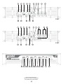
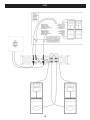
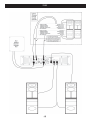
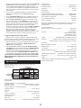
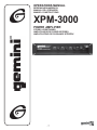
OPERATIONS MANUAL
BEDIENUNGSHANDBUCH
MANUAL DEL OPERADOR
MANUEL D’INSTRUCTIONS
XPM-3000
POWER AMPLIFIER
STEREO VERSTÄRKER
AMPLIFICADOR DE PODER ESTEREO
AMPLIFICATEUR DE PUISSANCE STÉRÉOV
(1)
1
2
11
12
1
2
11
12
16
3
3
17
4
5
13
14
4
5
13
14
18 19
16
6
7
8
10
9
230V
15
6
8
7
10
9
120V
15
17
18 20
16
Gemini Sound Products Corp.
120 Clover Place, Edison, NJ 08818• USA
Tel (732) 738-9003 • Fax (732) 738-9006
(2)
17
18 21
22
23
120V
(3)
230V
(4)
Introduction
Connections, Controls and Indicators
Congratulations on purchasing a Gemini XPM-3000 Power Amplifier.
This state of the art power amplifier includes the latest features and is
backed by a five year limited warranty. Prior to use, we suggest that you
carefully read all the instructions.
Rear Panel
Note: 120V and 230V units have different types of output
connectors on the rear panel.
Input Section:
Features
•
•
•
•
•
•
•
•
•
•
•
•
•
•
•
•
•
•
•
•
There are two parallel input connectors (one female XLR and one
1/4” jack) per channel. Either can be used as an input or as a link to
chain amplifiers.
MOSFET output stage technology for the finest sound quality and
reliability
3 Channel Operation: 2 Satellite Channels (Channels A and B) and 1
Subwoofer Channel
Full range operation mode for set up without subwoofer(s)
2-way Linkwitz-Riley crossover with switchable crossover frequency
for flexible set up of subwoofer and satellite channels
Switchable low frequency boost on the subwoofer channel optimizes
subwoofer performance
Stable operation of subwoofer channel down to a 2 Ohm load
Post crossover line level outputs for chaining additional subwoofers
and satellite speakers
High output power to drive professional loudspeakers without clipping
Oversized toroidal transformer, filter and heatsinks for better low end,
transparency and stability
Comprehensive protection circuitry (short, overheat, DC, subsonic
and RF filters, turn-on delay) with high current speaker protection
relays
True clip LEDs for better control
Signal ground lift switch eliminates hum from connection loops
Flexible input configuration with active balanced inputs; additional
input connectors to chain amps
Outputs: 5-way binding posts in 120V; Neutrik Speakon connectors in
230V
2 parallel 5-way binding posts on the subwoofer output (in 120V only)
allows for easy set up with dual subwoofers
Efficient dual aluminum extrusion heatsink design for thermal stability
and reliability
Front-to-Rear airflow with 2 speed dual fan control
Turn-on In-rush current limiting circuitry
Compact 2U well balanced enclosure
Steel reinforced chassis construction for durability and longevity
XLR Input Jacks (11, 14): electronically balanced inputs accept a
standard XLR male connector. Pin 1 = shield/ground, pin 2 = hot or
positive (+) and pin 3 = cold or negative (-).
1/4" Input Jacks (12, 13): accept a balanced as well as an unbalanced
line level signal. The unbalanced line uses a standard tip-sleeve
connection. The tip is positive and the sleeve is negative/ground. The
balanced line uses a tip-ring-sleeve connection. Tip = hot or positive
(+), ring = cold or negative (-), and sleeve = shield/ground.
Signal Ground Lift Switch (15) is used to lift the balanced input
connectors’ ground/shield from the amplifier’s ground. When the
signal ground is lifted, the sound source disconnects from the
amplifier’s ground preventing ground loops which can generate hum
and noise. See the Signal Ground Lift Switch Instructions for more
detail.
AC Power Section:
Fuse (7): replace fuse with those of proper type and rating.
AC Cord Outlet (6) is used to attach the power cord to the unit.
Signal Processing Section:
Disconnect the unit from the AC power source before making any
connections.
Crossover Switch (3): Use the crossover
switch to set the crossover frequency
between the subwoofer and the satellite
channels (Channels A and B) at 120 Hz or
180 Hz. Or you can set the crossover
switch to FULL RANGE if you do not wish
to use a subwoofer (the full range signal
will then go to the satellite channels).
Low Frequency Boost Switch (4): The LF Boost Switch can be used to
optimize the performance of the subwoofer. The LF boost effect uses
specialized filter circuitry, including a subsonic filter, to cut off
subsonic frequencies which keeps the subwoofer from wasting
available energy. The filter also provides an
optional +3 dB or +6 dB boost at 40 Hz which
is suitable for most subwoofers. The circuitry
optimizes the performance of the
subwoofer by focusing the signal’s energy
to match the subwoofer’s characteristics.
Set the switch to be FLAT, +3 dB or +6
dB based on your subwoofer and your
experience.
Cautions
Read all operating instructions before using this equipment.
To reduce the risk of electrical shock, do not open the unit. There
are NO USER REPLACEABLE PARTS INSIDE. Please contact the
Gemini Service Department or your authorized dealer to speak to a
qualified service technician.
Be sure to allow adequate front and rear ventilation to avoid possible
heat damage to your equipment.
Be sure that AC power is OFF and all level controls are set to MINIMUM
before making connections. This will eliminate any chance of
unexpected, loud audio transients that could damage your speaker
systems.
NOTE: The LF Boost settings only effect the subwoofer
channel and will not effect the satellite channels.
Be sure that AC power is OFF when changing modes of operation and
when changing the position of the ground lift switch.
Line Outputs (1, 2, 5): the amplifier has quasi balanced post crossover
line outputs. The line outputs connectors are 1/4” TRS and can be
used to connect to additional amplifiers (optional).
DO NOT EXPOSE THIS UNIT TO RAIN OR MOISTURE. Operators of
electronic equipment should in no way be in contact with water.
Output Section:
Speaker Outputs:
When connecting to AC power line be sure you haven’t lost the ground
connection by using an adapter or extension cord without a 3 prong plug.
Pay close attention to polarity (shown on the back of the unit) when
connecting your speakers. Connecting your speaker systems using the
wrong polarity will not damage your speakers, but it will impact the
quality of the sound (lack of bass and incorrect stereo image).
DO NOT USE ANY SPRAY CLEANER OR LUBRICANT ON ANY
CONTROLS OR SWITCHES.
Speaker Outputs for 120V Unit (8, 9, 10): the speaker output
connectors are 5-way binding posts that will accept standard banana
plugs, spade lugs or bare wire. Make sure that all the connections are
clean when using bare wire connections. If any strands of wire from
(5)
Operating Instructions
one connector touch the adjacent connector, the sound will be
distorted, and your amplifier will overheat and go into protection
mode.
THE AMPLIFIER’S POWER MUST BE TURNED OFF
WHEN CHANGING SETTINGS.
NOTE (120V only): Two subwoofer output connectors are
provided to connect two subwoofers with separate cables.
These outputs are wired in parallel and are connected to a
mono subwoofer channel (subwoofer output is not
directional and does not require a stereo signal). The
combined load for the subwoofer channel must not be less
than 2 Ohms (a single 2 Ohm speaker OR two 4 Ohm
speakers OR four 8 Ohm speakers).
Using the Amplifier With Subwoofer(s) and Satellite
Speakers
The XPM-3000 has two channels for stereo operation and a common
subwoofer channel. The amplifier has a built in crossover to separate the
input signal between the stereo satellite channels and the mono
subwoofer channel (the low frequency signal feeding the subwoofer is
not directional and does not require stereo operation). The amplifier also
provides an optional low frequency boost for the subwoofer channel to
optimize the performance of your subwoofer.
Speaker Outputs for 230V Unit (8, 9, 10): Neutrik Speakon connectors
are provided to connect speakers to the amplifier quickly and easily.
They are high current rated and provide very stable and durable
contacts. Every Speakon connector has pin 1- as negative and pin
1+ as positive.
WARNING: The XPM-3000 amplifier is designed to handle
low impedance loads and will operate normally with most
2 Ohm subwoofers or subwoofer combinations. The
amplifier will operate normally with most 4 Ohm speakers
on the satellite channels. However, for optimal
performance and reliability we recommend using
subwoofers and speakers with higher impedance (4 Ohms
for the subwoofer and 8 Ohms for the satellite channels).
1. With the power off, connect your input cables to the channel A and B
inputs using either the XLR INPUT JACKS (11, 14) or 1/4" INPUT
JACKS (12, 13) for each channel. The other channel A and channel
B inputs can be used to link to an additional amplifier.
2. Connect the subwoofer(s) to the subwoofer SPEAKER OUTPUT(S)
(10). Connect the full range loudspeakers to the channel A and
channel B SPEAKER OUTPUTS (8, 9). THE TOTAL SPEAKER
LOAD MUST BE AT LEAST 4 OHMS PER CHANNEL FOR THE
SATELLITE CHANNELS AND 2 OHMS FOR THE SUBWOOFER. If
you try to operate at a lower impedance, the amplifier will overheat
and then go into protection mode and stop operation until you correct
the load conditions.
NOTE: There are no bridge connections in this amplifier.
Please refer to the terminals’ color coding for proper
connection polarity.
Power (23): the power switch turns the unit on and off.
3. If you choose to use additional amplifiers, connect the additional
amplifiers to the XPM-3000 using the LINE OUTPUT (1, 2, 5)
connectors.
Power LED (22): the power LED lights when the power is on. If the
power LED does not light, refer to the trouble shooting guide.
NOTE: The line outputs tap the signal after the crossover
and the low frequency boost but before the level controls.
Signal LED (16): the signal LEDs for each channel show when a signal
is present.
4. Use the CROSSOVER SWITCH (3) to set the crossover frequency
between the subwoofer and the satellite channels (Channels A and B)
at 120 Hz or 180 Hz.
Front Panel
Clip LED (17): the amplifier has true clip LEDs to help you properly
control the amplifier’s output and achieve undistorted sound. The clip
LEDs for each channel light when your signal level is so strong that
the distortion reaches 1% THD. The clip LED should not remain
constantly on or flash repeatedly during operation. For clean sound
reproduction, the clip should only light occasionally for an instant. If
the LED remains on or flashes repeatedly, you will hear distorted
sound that can be damaging to your speaker system. If this occurs,
reduce the signal level by lowering the input level control for the
channel that is clipping or reduce the level at the source. If the clip
LED lights when no signal is present, it may indicate a RF signal on
the output which may cause damage to speakers (the RF signal will
not be audible).
5. Use the LOW FREQUENCY BOOST SWITCH (4) to optimize the
performance of the subwoofer. The LF boost effect uses specialized
filter circuitry, including a subsonic filter, to cut off subsonic
frequencies which keeps the subwoofer from wasting available
energy. The filter also provides an optional +3 dB or +6 dB boost at
40 Hz which is suitable for most subwoofers. Set the switch to be
FLAT, +3 dB or +6 dB based on your subwoofer and your experience.
NOTE: The LF Boost settings only effect the subwoofer
channel and will not effect the satellite channels.
6. With the LEVEL CONTROLS (19, 20, 21) of the channels set to zero
(fully counterclockwise), turn the POWER (23) on. Apply a signal to
the input of the amplifier. The level of the input signal should be as
high as you will ever need it to be. This way, it will be as high above
the amplifier’s noise floor as possible, ensuring an excellent
performance and signal to noise ratio. Adjust the LEVEL CONTROLS
for each channel to achieve the desired maximum listening level.
Note, when the clip LEDs light, there is distortion present in the
amplifier’s output section. If a clip LED remains on or flashes
repeatedly, reduce the signal level by lowering the input level control
for the channel that is clipping or reduce the level at the source.
Protect LED (18): when you first turn on the amplifier, the protect LEDs
light briefly during a turn-on delay which indicates that the outputs are
disconnected internally. There will be an audible click when the
outputs reconnect and the protect LEDs will turn off. Otherwise, the
protect LED indicates that there is a problem either in the amplifier’s
external connections, load or temperature conditions or its internal
functions. If one of these situations occur, the amplifier senses the
problem and automatically switches into protection mode. The LED
will light to warn you of the trouble and the amplifier will stop working.
If this occurs, switch off the amplifier and refer to the Trouble
Shooting Guide. If the protect LED remains lit when resuming
amplifier operation, do not use the amplifier and contact an
authorized service technician.
Using the Amplifier Without Subwoofer(s)
The XPM-3000 gives you the option of operating the amplifier as you
would a conventional amplifier, without using subwoofer(s). This flexibility
is especially useful if you don’t want to transport your subwoofers at
times.
Level Controls (19, 20, 21): establish the input levels required for each
channel.
1. With the power off, connect your input cables to the channel A and B
inputs using either the XLR INPUT JACKS (11, 14) or 1/4" INPUT
JACKS (12, 13) for each channel. The other channel A and channel
B inputs can be used to link to an additional amplifier.
(6)
2. Connect the loudspeakers to the channel A and channel B SPEAKER
OUTPUTS (8, 9). THE TOTAL SPEAKER LOAD MUST BE AT
LEAST 4 OHMS PER CHANNEL FOR CHANNELS A AND B. If you
try to operate at a lower impedance, the amplifier will overheat and
then go into protection mode and stop operation until you correct the
load conditions.
Damping Factor:
Channels A and B................................................................>300 @ 8 Ohms
Subwoofer Channel.............................................................>600 @ 8 Ohms
3. If you choose to use additional amplifiers, connect the additional
amplifiers to the XPM-3000 using the LINE OUTPUT (1, 2)
connectors.
Input Sensitivity:
Channels A and B (for rated power at 8 Ohms)....................>300 @ 8 Ohms
Subwoofer Channel (for rated power at 4 Ohms)...................>600 @ 8 Ohms
4. Set the CROSSOVER SWITCH (3) to FULL RANGE so that the full
range signal will go to the satellite channels (Channels A and B).
Input Impedance Unbalanced....................................................10 kOhms
Slew Rate.................................................................................25 V/µS
Voltage Gain.........................................................................................33 dB
Input Impedance Balanced.......................................................20 kOhms
5. With the LEVEL CONTROLS (20, 21) of the channels set to zero
(fully counterclockwise), turn the POWER (23) on. Apply a signal to
the input of the amplifier. The level of the input signal should be as
high as you will ever need it to be. This way, it will be as high above
the amplifier’s noise floor as possible, ensuring an excellent
performance and signal to noise ratio. Adjust the LEVEL CONTROLS
for each channel to achieve the desired maximum listening level.
Note, when the clip LEDs light, there is distortion present in the
amplifier’s output section. If a clip LED remains on or flashes
repeatedly, reduce the signal level by lowering the input level control
for the channel that is clipping or reduce the level at the source.
Power consumption.....................................................................1200 VA
Note: power consumption is given at rated power at 8 Ohms per channel
(Channels A and B), 4 Ohms on the subwoofer channel, all three
channels driven.
AC Power Requirement:
(power connection is factory configured)............................120V/ 60 Hz
230V/ 50 Hz
Indicators.......................................................................1 Power Indicator
1 Signal LED per channel
1 Clip LED per channel
1 Protect LED per channel
Using the Signal Ground Lift Switch
Depending on your system configuration, sometimes applying the
ground will create a quieter signal path. Sometimes lifting the ground can
eliminate ground loops and hum to create a quieter signal path.
Cooling....................................2 Speed Dual Fan; Front-to-Rear Forced Air
1. With the power amp on, listen to the system in idle mode (no signal
present) with the ground applied (the SIGNAL GROUND LIFT
SWITCH (15) in the left position).
Connectors:
2. Then turn the power off before moving the SIGNAL GROUND
LIFT SWITCH (15). Lift the ground by moving the SIGNAL GROUND
LIFT SWITCH to the right, turn the power back on and listen to
determine which position will provide a signal devoid of background
noise and hum. Keep the SIGNAL GROUND LIFT SWITCH in the
ground position if the noise level remains the same in either position.
Balanced Inputs..............................................................XLR Female Jack
CAUTION: DO NOT TERMINATE THE AC GROUND ON THE POWER
AMPLIFIER IN ANY WAY. TERMINATION OF THE AC GROUND CAN
BE HAZARDOUS.
Dimensions...................................19" x 13.75" x 3.5" (483 x 350 x 89 mm)
Protection........................Short Circuit, DC, Thermal Cut-off, Sub/ultrasonic
Frequency Filters, In-rush Current Limiter, Turn-on Delay
Balanced/Unbalanced Inputs.......................................................1/4" Jack
Line Outputs...............................................................................1/4" Jack
Speaker Outputs (120V unit).......................................5-way binding posts
2 Parallel 5-way binding posts for subwoofers
Speaker Outputs (230V unit)...........Speakons (ch.A, ch.B and subwoofer)
Weight....................................................................................31 lbs (14 kg)
* Specifications and design are subject to change without notice for
purpose of improvement.
Specifications
Output Power EIA: 1kHz @ 1% THD (100 Hz @ 1% THD for the
subwoofer channel)
Subwoofers
Ouput Power Chart:
Impedance
Not
Used
8 Ohms
4 Ohms
2 Ohms
260
425
600
Not Used
A and B
Speakers
8 Ohms
220
4 Ohms
300
200
220
190
270
380
350
165
250
540
530
Note: the power for channels A and B is given as per channel, both
channels driven
Frequency Response - 3 Channel Operation:
Channels A and B.......................................Crossover Frequency - 60 kHz
Subwoofer Channel.....................................20 Hz - Crossover Frequency
Frequency Response - Full Range Operation:
Channels A and B.................................................................20 Hz - 60 kHz
Crossover:
Type.................................................................2nd order Linkwitz-Riley
Crossover Frequency....................................................120 Hz/180 Hz
Low Frequency Boost:
Boost Frequency..............................................................................40 Hz
Boost Level..............................................................................+3 dB/+6 dB
Signal to Noise Ratio..........................100 dB below rated power, 8 Ohms
(7)
SYMPTOM
UNIT DOES NOT PRODUCE SOUND. POWER
LED DOES NOT LIGHT.
CAUSE
• POWER SWITCH NOT IN ON POSITION.
• MOVE POWER SWITCH TO ON POSITION.
• POWER CABLE NOT CONNECTED TO AMPLIFIER
OR TO OUTLET.
• CONNECT POWER CABLE TO AC SUPPLY.
• AC OUTLET NOT ACTIVE.
• REPLACE AMPLIFIER MAIN POWER FUSE ON REAR
PANEL WITH CORRECT TYPE AND RATING.
• MAIN AMPLIFIER FUSE DEFECTIVE.
POWER LED LIGHTS, BUT NO SOUND IS
PRODUCED BY AMPLIFIER.
SOLUTION
• NO INPUT SOURCE SIGNAL.
• INPUT SOURCE NOT CONNECTED.
• INPUT CONNECTING CABLE DEFECTIVE.
• SPEAKER(S) NOT CONNECTED.
• SPEAKER CABLE DEFECTIVE.
• SPEAKER SYSTEM(S) INOPERATIVE.
• CHECK CONDITION OF OUTLET.
• CHECK FOR PROPER FUNCTION OF INPUT
SOURCE DEVICE.
• CHECK INPUT CABLES AND CONNECTIONS.
REPLACE QUESTIONABLE CABLES WITH KNOWN
GOOD CABLES.
• CHECK SPEAKER CABLES AND CONNECTIONS.
REPLACE QUESTIONABLE CABLES WITH KNOWN
GOOD CABLES.
• AMPLIFIER’S LEVEL CONTROLS ARE SET TO
ZERO.
• CHECK OPERATING CONDITION AND STATUS OF
SPEAKER SYSTEM(S). BE SURE THE LEVEL
CONTROLS ARE PROPERLY SET.
SOUND IS PRESENT BUT VOLUME IS TOO
LOW EVEN THOUGH SOURCE DEVICE IS
SET TO A HIGH LEVEL.
• AMPLIFIER INPUT LEVEL CONTROLS ARE SET
TOO LOW.
• ADJUST LEVEL CONTROLS AS PER INSTRUCTIONS.
• WRONG PIN CONNECTIONS IN CABLES.
• USE CORRECT CABLES (AS SHOWN ON BACK OF
UNIT).
VERY LITTLE OR NO OUTPUT FROM
SUBWOOFER OR
NO BASS FROM FULL RANGE SPEAKERS
WHEN
OPERATING
WITHOUT
SUBWOOFERS.
• FREQUENCY SWITCH IS IN THE FULL RANGE
MODE POSITION.
• MOVE THE FREQUENCY SWITCH TO THE 120 HZ
OR THE 180 HZ POSITION.
LOUD 50/60 HZ OR 100/120 HZ HUM IS
HEARD AT ALL TIMES THROUGH THE
SPEAKER SYSTEMS.
• IMPROPER OR DEFECTIVE GROUND
CONNECTION AT INPUTS. IMPROPER OR
DEFECTIVE GROUND AT INPUT SOURCE
DEVICE(S).
• CHECK FOR PROPER AC LINE GROUND ON POWER
AMP AND ALL INPUT DEVICES.
• IMPROPER OR DEFECTIVE GROUND
CONNECTION ON AC OUTLET.
SOUND IS DISTORTED.
• CHECK INPUT CABLES FOR ALL SOURCE DEVICES
AND SIGNAL PROCESSING AS WELL AS INPUT
CABLES TO POWER AMPLIFIER. CHECK POSITION
OF GROUND LIFT SWITCH AS PER INSTRUCTIONS
FOR LIFTING THE GROUND.
• GROUND LOOP THROUGH AC LINE
CONNECTION/RACK MOUNTING.
• NEVER LIFT THE AC LINE GROUND ON THE POWER
AMPLIFIER. IF YOU ARE NOT TOTALLY FAMILIAR WITH
GROUND LIFTING OR UNIFICATION PROCEDURES,
DO NOT ATTEMPT THEM WITHOUT FIRST
CONSULTING YOUR DEALER OR A QUALIFIED
SOUND TECHNICIAN FOR MORE INFORMATION ON
GROUNDING. IMPROPERLY DONE, SUCH
PROCEDURES CAN POSE A SAFETY AND/OR FIRE
HAZARD.
• DISTORTION OCCURRING IN SOURCE DEVICE.
• CHECK CLIP INDICATORS ON INPUT SOURCE
DEVICES AND RESET LEVELS IF NECESSARY TO
ELIMINATE DISTORTION.
• INPUT LEVEL IS SET TOO HIGH.
• ADJUST LEVEL CONTROLS AS PER INSTRUCTIONS.
PROTECT LED REMAINS LIT OR GOES ON
AND OFF INTERMITTENTLY AFTER USING
AMPLIFIER FOR A SHORT TIME.
• UNIT IS OPERATING AT EXCESSIVELY HIGH
TEMPERATURE.
• EXTREMELY LOW SPEAKER IMPEDANCE.
• SHORT IN SPEAKER CONNECTORS,
SPEAKER CABLE OR SPEAKER SYSTEM.
• CHECK THAT AMPLIFIER IS ADEQUATELY
VENTILATED ON THE FRONT AND REAR PANELS
WHERE THE AIR VENTS AND FANS ARE LOCATED.
IF OVERHEATED, LET THE AMPLIFIER COOL DOWN
BEFORE APPLYING AN INPUT SIGNAL.
• VERIFY SPEAKER SYSTEM IMPEDANCES. BE SURE
THE TOTAL SPEAKER SYSTEM IMPEDANCE IS AT
LEAST 4 OHM PER CHANNEL FOR CHANNELS A AND
B, AND AT LEAST 2 OHM FOR THE SUBWOOFER
CHANNEL. IF YOU ARE NOT SURE OF YOUR TOTAL
SPEAKER IMPEDANCE LOAD, CONTACT YOUR
DEALER FOR MORE INFORMATION.
• CHECK CONDITION OF SPEAKER CABLES.
• IF USING BARE WIRE CONNECTIONS ON THE
OUTPUTS OF THE AMPLIFIER, BE SURE THAT NO
STRANDS FROM ONE CONNECTOR ARE TOUCHING
ANY OTHER CONNECTOR.
FUSE BLOWS INTERMITTENTLY.
• SPEAKER LOAD IMPEDANCE IS TOO LOW.
• CHECK FOR SHORTS ON THE OUTPUTS.
• TYPE OR RATING OF THE FUSE IS NOT
CORRECT.
• CHECK YOUR SPEAKER IMPEDANCE (INFO FROM
DEALER).
• CHECK THAT THE FUSE TYPE AND RATING IS
CORRECT.
PROTECT LED(S) STAY ON WITH NO
SPEAKERS CONNECTED AND WITH THE
AMPLIFIER COOLED DOWN.
• FAILED AMPLIFIER.
• CONTACT THE GEMINI SERVICE DEPARTMENT OR
YOUR AUTHORIZED DEALER TO SPEAK TO A
QUALIFIED SERVICE TECHNICIAN. IN THE U.S.A. CALL
1-732-969-9000
(8)
In the USA: If you experience problems with this unit,
call 1-732-738-9003 for Gemini Customer Service.
Do not attempt to return this equipment to your dealer.
Parts of the design of this product may be protected by worldwide
patents.
Information in this manual is subject to change without notice and does
not represent a commitment on the part of the vendor. Gemini Sound
Products Corp. shall not be liable for any loss or damage whatsoever
arising from the use of information or any error contained in this
manual.
No part of this manual may be reproduced, stored in a retrieval system or
transmitted, in any form or by any means, electronic, electrical,
mechanical, optical, chemical, including photocopying and recording, for
any purpose without the express written permission of Gemini Sound
Products Corp.
It is recommended that all maintenance and service on this product is
performed by Gemini Sound Products Corp. or its authorized agents.
Gemini Sound Products Corp. will not accept liability for loss or damage
caused by maintenance or repair performed by unauthorized personnel.
Worldwide Headquarters • 120 Clover Place, Edison, NJ 08837 • USA
Tel: (732) 738-9003 • Fax: (732) 738-9006
France • G.S.L. France • 11, Avenue Leon Harmel, Z.I. Antony, 92160 Antony, France
Tel: + 33 (0) 1 55 59 04 70 • Fax: + 33 (0) 1 55 59 04 80
Germany • Gemini Sound Products GmbH • Ottostrasse 6, 85757 Karlsfeld, Germany
Tel: 08131 - 39171-0 • Fax: 08131 - 39171-9
UK • Gemini Sound Products • Unit C4 Hazleton Industrial Estate, Waterlooville, UK P08 9JU
Tel: 087 087 00880 • Fax: 087 087 00990
Spain • Gemini Sound Products S.A. • Rosello, 516, Barcelona, Spain, 08026
Tel: 349-3435-0814 • Fax: 3493-347-6961
© Gemini Sound Products Corp. 2002
(28)
All Rights Reserved