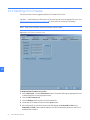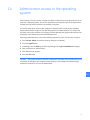
1
GE
Entellisys™ Low Voltage Switchgear
System Administrator Manual
DEH-230
Warnings, Cautions, and Notes as used in this publication
Warnings
WARNING! Warning notices are used in this publication to emphasize that hazardous voltages,
currents, or other conditions that could cause personal injury exist in this equipment or may be
associated with its use.
Warning notices are also used for situations in which inattention or lack of equipment knowledge
could cause either personal injury or damage to equipment.
Cautions
CAUTION: Caution notices are used for situations in which equipment might be damaged if care is
not taken.
Notes
NOTE: Notes call attention to information that is especially significant to understanding and
operating the equipment.
This document is based on information available at the time of its publication. While efforts have been
made to ensure accuracy, the information contained herein does not cover all details or variations in
hardware and software, nor does it provide for every possible contingency in connection with
installation, operation, and maintenance. Features may be described in here that are not present in all
hardware and software systems. GE Consumer & Industrial assumes no obligation of notice to holders
of this document with respect to changes subsequently made.
GE Consumer & Industrial makes no representation or warranty, expressed, implied, or statutory, with
respect to, and assumes no responsibility for the accuracy, completeness, sufficiency, or usefulness of
the information contained herein. No warrantees of merchantability or fitness for purpose shall apply.
Entellisys™, EntelliGuard™, and FlexLogic™ are trademarks of the General Electric Company.
Modbus RTU is a registered trademark of AEG Schneider Automation.
©Copyright 2005 General Electric
All Rights Reserved
How to contact us
Please have your Entellisys System Summary # and Sub # ready when calling. This information can be
found on the Entellisys HMI on the System Health screen by clicking the Job Info button.
Post Sales Service
GE Switchgear
510 Agency Road
West Burlington, IA 52655
Phone (toll free): 1-888-437-3765
Additional information:
www.entellisys.com/support
For Option Upgrades and CPU Replacement needs only, e-mail us at [email protected].
Contents
1 System administrator roles and responsibilities
1.1 Security Champion . . . . . . . . . . . . . . . . . . . . . . . . . . . . . . . . . . . . . . . . . . . . . . . . . . . . . . . . . . . . . . . . . . . . . . . . . . . . . . . . . . . . 7
1.1.1 System Maintenance . . . . . . . . . . . . . . . . . . . . . . . . . . . . . . . . . . . . . . . . . . . . . . . . . . . . . . . . . . . . . . . . . . . . . . . . . . . . . 7
2 Pre-programming settings prior to switchgear arrival
3 Commissioning the switchgear
4 Passwords
4.1 HMI permissions and passwords . . . . . . . . . . . . . . . . . . . . . . . . . . . . . . . . . . . . . . . . . . . . . . . . . . . . . . . . . . . . . . . . . . . . . . 13
4.1.1 Setting HMI login permissions and passwords . . . . . . . . . . . . . . . . . . . . . . . . . . . . . . . . . . . . . . . . . . . . . . . . . . . . 13
4.1.2 Resetting forgotten HMI passwords . . . . . . . . . . . . . . . . . . . . . . . . . . . . . . . . . . . . . . . . . . . . . . . . . . . . . . . . . . . . . . 15
4.2 Modbus® security . . . . . . . . . . . . . . . . . . . . . . . . . . . . . . . . . . . . . . . . . . . . . . . . . . . . . . . . . . . . . . . . . . . . . . . . . . . . . . . . . . . . 16
4.2.1 Control and settings passwords . . . . . . . . . . . . . . . . . . . . . . . . . . . . . . . . . . . . . . . . . . . . . . . . . . . . . . . . . . . . . . . . . . 16
4.2.2 Local HMI . . . . . . . . . . . . . . . . . . . . . . . . . . . . . . . . . . . . . . . . . . . . . . . . . . . . . . . . . . . . . . . . . . . . . . . . . . . . . . . . . . . . . . . 17
5 Time synchronization
5.0.1 Setting time in the HMI. . . . . . . . . . . . . . . . . . . . . . . . . . . . . . . . . . . . . . . . . . . . . . . . . . . . . . . . . . . . . . . . . . . . . . . . . . . 19
6 Configuring the switchgear for remote communications
6.1 Setting IP addresses for remote communication . . . . . . . . . . . . . . . . . . . . . . . . . . . . . . . . . . . . . . . . . . . . . . . . . . . . . . . 22
6.1.1 HMI IP address . . . . . . . . . . . . . . . . . . . . . . . . . . . . . . . . . . . . . . . . . . . . . . . . . . . . . . . . . . . . . . . . . . . . . . . . . . . . . . . . . . 22
6.1.2 CPU IP address . . . . . . . . . . . . . . . . . . . . . . . . . . . . . . . . . . . . . . . . . . . . . . . . . . . . . . . . . . . . . . . . . . . . . . . . . . . . . . . . . . 22
6.2 Network security/VPN device . . . . . . . . . . . . . . . . . . . . . . . . . . . . . . . . . . . . . . . . . . . . . . . . . . . . . . . . . . . . . . . . . . . . . . . . . 24
7 Installing and configuring remote HMI software
8 Settings files and offline system configuration
8.1 Offline mode . . . . . . . . . . . . . . . . . . . . . . . . . . . . . . . . . . . . . . . . . . . . . . . . . . . . . . . . . . . . . . . . . . . . . . . . . . . . . . . . . . . . . . . . . 29
8.2 Viewing and comparing settings files . . . . . . . . . . . . . . . . . . . . . . . . . . . . . . . . . . . . . . . . . . . . . . . . . . . . . . . . . . . . . . . . . . 31
8.3 Writing settings to a live system. . . . . . . . . . . . . . . . . . . . . . . . . . . . . . . . . . . . . . . . . . . . . . . . . . . . . . . . . . . . . . . . . . . . . . . 33
8.4 Resetting the offline settings files to the current settings . . . . . . . . . . . . . . . . . . . . . . . . . . . . . . . . . . . . . . . . . . . . . . . 34
9 Sharing files across HMIs
9.1 Publishing shared files . . . . . . . . . . . . . . . . . . . . . . . . . . . . . . . . . . . . . . . . . . . . . . . . . . . . . . . . . . . . . . . . . . . . . . . . . . . . . . . . 35
9.2 Updating an HMI with shared files. . . . . . . . . . . . . . . . . . . . . . . . . . . . . . . . . . . . . . . . . . . . . . . . . . . . . . . . . . . . . . . . . . . . . 36
10 System archives
10.1 Restoring an archive . . . . . . . . . . . . . . . . . . . . . . . . . . . . . . . . . . . . . . . . . . . . . . . . . . . . . . . . . . . . . . . . . . . . . . . . . . . . . . . . 38
10.2 Creating an archive . . . . . . . . . . . . . . . . . . . . . . . . . . . . . . . . . . . . . . . . . . . . . . . . . . . . . . . . . . . . . . . . . . . . . . . . . . . . . . . . . 38
11 Feature options
11.1 Viewing installed options . . . . . . . . . . . . . . . . . . . . . . . . . . . . . . . . . . . . . . . . . . . . . . . . . . . . . . . . . . . . . . . . . . . . . . . . . . . . 41
11.2 Upgrading options . . . . . . . . . . . . . . . . . . . . . . . . . . . . . . . . . . . . . . . . . . . . . . . . . . . . . . . . . . . . . . . . . . . . . . . . . . . . . . . . . . 42
12 Preparing and configuring a replacement CPU
12.1 Part I – Preparation for replacement of a CPU . . . . . . . . . . . . . . . . . . . . . . . . . . . . . . . . . . . . . . . . . . . . . . . . . . . . . . . . 45
12.2 Part II – Replacing the CPU. . . . . . . . . . . . . . . . . . . . . . . . . . . . . . . . . . . . . . . . . . . . . . . . . . . . . . . . . . . . . . . . . . . . . . . . . . . 48
Contents
5
13 Other maintenance functions
13.1 Viewing and updating circuit breaker names . . . . . . . . . . . . . . . . . . . . . . . . . . . . . . . . . . . . . . . . . . . . . . . . . . . . . . . . . 55
13.2 Viewing and updating circuit breaker accessories . . . . . . . . . . . . . . . . . . . . . . . . . . . . . . . . . . . . . . . . . . . . . . . . . . . . 56
13.3 Installing CPU firmware. . . . . . . . . . . . . . . . . . . . . . . . . . . . . . . . . . . . . . . . . . . . . . . . . . . . . . . . . . . . . . . . . . . . . . . . . . . . . . 58
13.4 Viewing zone configuration . . . . . . . . . . . . . . . . . . . . . . . . . . . . . . . . . . . . . . . . . . . . . . . . . . . . . . . . . . . . . . . . . . . . . . . . . . 59
14 Administrator access to the operating system
6
Contents
1
System administrator roles and
responsibilities
1
The Entellisys™ Low Voltage Switchgear system requires a System Administrator for oversight
of critical functions. Those critical functions are described in this guide.
Chapter 1 provides an overview of the roles and responsibilities.
The following chapters describe how to perform the functions, in detail.
1.1 Security Champion
The most important role of the System Administrator is to control the access to the system.
There are several forms of access:
• HMI Login Access: Entellisys provides programmable permissions and passwords. The
System Administrator determines who needs what permissions and assigns login names
and passwords.
• Modbus® Settings and Control Access.
• Remote Access to the Switchgear over a company network.
Security Reminders
• Limit the access level handed out to only the required permissions.
• Stress the importance of keeping passwords secret.
• If you believe passwords have been compromised, change them immediately.
• Always log out before leaving the local HMI, or leave the system logged in as Guest.
Alternatively, the switchgear can be configured to automatically log out after a time period.
(For details, on the Main Menu, click User Settings, and then click HMI Preferences.)
1.1.1 System Maintenance
The System Administrator is also responsible for system maintenance as described in this
document.
Security Champion
7
1
8
System administrator roles and responsibilities
2
Pre-programming settings prior to
switchgear arrival
2
Entellisys provides a method for users to work on the system settings before the switchgear
arrives. Once the gear is installed and control power is applied, the saved settings can be written
to the system.
To pre-program Settings, the “Entellisys Remote HMI – User Interactive version” must be
purchased. GE will ship the Remote HMI software, System Administrator Manual (this manual),
and a System Archive when the switchgear ships from the factory.
The following steps should be performed to begin pre-programming:
• Step 1: Install the “Entellisys Remote HMI – User Interactive version” software.
See Installing and configuring remote HMI software on page 25 for instructions.
• Step 2: Install the System Archive provided by GE.
See Restoring an archive on page 38 for instructions.
• Step 3: Change to Offline Mode.
See Offline mode on page 29 for instructions and for offline mode capabilities.
• Step 4: Set User Settings.
See DEH-231 Entellisys Low Voltage Switchgear System User Manual.
• Step 5: Install and Commission the Switchgear.
See Commissioning the switchgear on page 11 for instructions.
• Step 6: Configure the System for Remote Communications.
See Configuring the switchgear for remote communications on page 21 for instructions.
• Step 7: Write saved Settings to System.
See Writing settings to a live system on page 33 for instructions.
9
2
10
Pre-programming settings prior to switchgear arrival
3
Commissioning the switchgear
Installing and starting up the switchgear is an important event for the System Administrator. The
following steps must be followed when commissioning the switchgear.
• Step 1: Reset Passwords.
See Passwords on page 13.
• Step 2: Set User Settings.
See DEH-231 Entellisys Low Voltage Switchgear System User Manual.
• Step 3: Set Local HMI flags.
See Local HMI on page 17.
• Step 4: Set System Time Synchronization.
See Time synchronization on page 19.
• Step 5: Configure System for Remote Communications.
See Configuring the switchgear for remote communications on page 21.
11
3
3
12
Commissioning the switchgear
4
Passwords
4.1 HMI permissions and passwords
The Entellisys HMI requires a login name and password. This login sets the permissible actions
for the session. Each user's permissions are programmable to provide flexibility. Only the
Administrator can set permissions, login names, and passwords.
4
CAUTION: Enabling Group Permissions for features that allow the changing of settings and/or
access to control functions must be restricted to accounts for qualified personnel only. As a
reminder, users with such privileges will be presented with the following screen upon initial login:
Figure 4-1 Initial login Caution screen
4.1.1 Setting HMI login permissions and passwords
A Group defines the permission categories for a type or group of users. By default,
Administrator, Operator, and Guest groups are defined with preset permissions as examples.
Additional groups may be created with programmable permissions.
Figure 4-2 Programmable permissions screen
HMI permissions and passwords
13
Once Groups are established, individual Users can be created. Users can have individual login
names and passwords.
Passwords consist of 3-20 alphanumeric characters. Both login names and passwords are
case-insensitive.
NOTE: There are three predefined Groups that cannot be modified. Beneath those Groups are
two Users that are fixed and cannot be modified. The passwords for all can be changed. The
predefined groups and users are:
4
Group: Administrator
Group: Operator
Group: Guest
User: Administrator
User: <not defined>
User: Guest
Figure 4-3 User Administration screen in the HMI
To set permissions for a user Group
1. On the Main Menu, click the User Administration button. Only Administrators can access
User Administration. For all others, the button will not appear on the Main Menu.
2. Click the desired user group to edit or click the Add Group button to define a new type of
user.
3. Change the permissions by selecting the appropriate check boxes in the permission list.
User will be granted this permission.
User will not have this permission.
4. Change the permissions by selecting the appropriate check boxes in the permission list.
14
Passwords
To change a password
1. On the Main Menu, click the User Administration button. Only Administrators can access
User Administration. For all others, the button will not appear on the Main Menu.
2. Select the desired user group on the left-side pane. Expand the group by clicking the +
symbol and click a user name.
3. Enter the new password in the New Password field.
4. Confirm your password by re-entering the new password in the Confirm Password field.
Click OK to save your new password (or click Cancel to exit).
4
5. In the right-side pane you can see “Permission”, “Contact Information”, and “Authentication”
details.
To verify the password change:
1. On the Main Menu, click the Change Users icon in upper right-hand corner.
Figure 4-4 Change Users icon
2. Enter the user name in the Login field.
3. Enter the new password in the password field.
4. Click Go. If successful, the Main Menu will display.
4.1.2 Resetting forgotten HMI passwords
Administrators have access permission to change passwords for all users in all groups.
NOTE: It is very important for the System Administrator to keep the Administrator password in
a safe location. Losing the Administrator password will require a GE Field Service visit to reset it.
GE offers an optional service to store the Administrator password at the request of customers.
In the event the password is lost, GE can provide the password to the customer over the phone,
without requiring a site visit.
Contact GE Post Sales Service for help (see How to contact us on page 2).
HMI permissions and passwords
15
4.2 Modbus® security
4.2.1 Control and settings passwords
The CPUs require extra passwords to change settings (i.e., Short Time pickup delay setting) and
to send commands (i.e., Open Breaker command). These passwords apply to all clients that
access the Entellisys system through Modbus communications including the Entellisys HMI,
SCADA, or Building Automation, etc.
4
NOTE: The system ships with default CPU Modbus Settings and Command passwords. The
System Administrator should change these passwords for added security.
The HMI can be configured to transparently send the passwords whenever needed or it can be
configured to require all users to re-enter the password when the action is attempted.
Figure 4-5 Modbus Security screen in the HMI
16
Passwords
To change the Settings and/or Command passwords
1. On the Main Menu, click the Maintenance button. The button will only be displayed if access
is allowed with the current login permissions.
2. Click the Modbus Security tab. The Modbus Security screen has options to change both
CPU A and CPU B Command and Settings passwords.
NOTE:
It is recommended that the passwords in CPU A and CPU B be set to the same value.
4
3. Enter the new commands password in the New Password field.
4. Re-enter the password in the Confirm Password field.
5. Click the Change button to download the password.
6. Select the desired Auto Send option.
Indicates the Auto Send option will transparently send the password each time a
command is sent to the CPU.
Disables the Auto Send option.The user will be prompted to enter the password (for the
CPU that is currently the default) each time a command is sent.
NOTE: For added security, it is recommended the Auto Send option be disabled. This will
require an additional password to be entered each time a command is performed.
4.2.2 Local HMI
An Entellisys system may have multiple HMI stations running. There are some functions that
should be performed by one HMI only. The “Local HMI” flag is provided to designate one HMI for
special functions.
The “Local HMI” flag affects the following functions:
• E-mail on Alarms is only sent from the HMI with the Local HMI flag set.
• Time Synchronization is only performed by the HMI with the Local HMI flag is set.
• “Block other HMIs” can be enabled/disabled only by the HMI with the Local HMI flag set. This
allows a user on the Local HMI to block all other HMIs from issuing control commands (i.e.,
Breaker Open), which may be desired during maintenance. For details on circuit breaker
control, see DEH-231 Entellisys Low Voltage Switchgear System User Manual, Chapter 3,
Basic Control.
Modbus® security
17
Figure 4-6 Breaker Control screen
4
• The CPU reserves a communication port for the HMI with the Local HMI flag set. The CPUs
can support up to 8 simultaneous communication ports for Modbus clients. Once the limit is
exceeded, clients will be blocked until a port is free. The Local HMI flag has special ports
reserved for its use to prevent other clients from locking it out.
NOTE:
All In-Gear and Near-Gear Touchscreen HMIs should have the “Local HMI” set.
To set an HMI as a local HMI
1. On the Main Menu, click the Maintenance button. The button will only be displayed if access
is allowed with the current login permissions.
2. Click the Modbus Security tab.
3. Select the Local HMI check box as shown in Figure 4-5.
4. Click the OK button to save changes (or click Cancel to cancel changes).
18
Passwords
5
Time synchronization
In the Entellisys System, time is recorded when events occur for diagnostic purposes. Events are
generated from both the HMI and the CPU components and the time stamps used are derived
from time set in the component.
One HMI in the system will be configured to synchronize time with the CPUs. Periodically, the
HMI will synchronize time to ensure the time in the two CPUs is consistent.
5
Time synchronization configuration is done by GE during the system start up.
NOTE: The System Administrator should periodically check the date and time set on all local
HMIs to ensure the event time stamps are accurate. It is especially important on the HMI
configured to time synch the CPUs.
5.0.1 Setting time in the HMI
To set time, log into the HMI Operating System with Administrator access (see Administrator
access to the operating system on page 61.) Double-click the Clock icon on the taskbar to set
date, time, and time zone. Restart the computer to revert to normal run mode with limited OS
access.
19
5
20
Time synchronization
6
Configuring the switchgear for remote
communications
The following is recommended to Configure the Entellisys Low Voltage Switchgear System for
remote communications:
Step 1: Acquire static IP addresses compatible on the company network.
NOTE:
Entellisys components are not DHCP-compatible.
6
The number of IP addresses required depends on the number of HMIs. The following number of
IP addresses is required:
• CPU A
• CPU B
• All In-Gear HMIs
• All Near-Gear HMIs
• All Remote HMIs
NOTE: Additional IP addresses might be required to configure a VPN/firewall appliance if one is
installed.
The subnet mask must be compatible with the network segment on which each device resides.
Gateway IP depends on the company network and needs to be acquired from the Network
Administrator.
Step 2: Reset the CPU IP Addresses.
See Setting IP addresses for remote communication on page 22.
Step 3: Reset the local HMI IP Addresses.
See Setting IP addresses for remote communication on page 22.
Step 4: Verify communication between the local HMIs and CPUs.
See Setting IP addresses for remote communication on page 22.
Step 5: Install and Configure a network security device such as a VPN/Firewall appliance. See
Network security/VPN device on page 24.
Step 6: Connect the Entellisys system to the company network via the VPN/Firewall appliance in
the switchgear.
Step 7: Verify communication between local HMI(s) and CPUs.
See Setting IP addresses for remote communication on page 22.
21
Step 8: Install Remote HMIs.
See Installing and configuring remote HMI software on page 25.
Step 9: Verify communication between Remote HMI and CPUs.
See Chapter 5.2. [dk: there is no section 5.2?]
6.1 Setting IP addresses for remote communication
6
6.1.1 HMI IP address
To change the HMI IP address
1. For the HMI touchscreen computer, login to the Operating System as Administrator. See
Administrator access to the operating system on page 61 for details.
2. Open the Control Panel, and then open the Network Connections dialog box.
3. Double-click the Local Area Connection 1.
4. In the TCP/IP Properties tab, set the new Local HMI IP address. Set the subnet mask to a
value compatible with the segment on which it resides.
By default the subnet mask is set to 255.255.255.0. The default touchscreen HMI IP address is
192.168.1.1 as delivered. The default IP address for each additional touchscreen HMI is
incremented by 1 in the right-most address.
6.1.2 CPU IP address
To change the CPU IP addresses
1. On the Main Menu, click User Settings.
2. Click HMI Preferences.
3. Click Communication.
4. Select either CPU A or CPU B by clicking the appropriate button.
5. Enter the new IP address. The IP address format is X.X.X.X where X is from 0 to 255.
22
Configuring the switchgear for remote communications
Figure 6-1 Set CPU IP Addresses screen
6
6. Click the Test Communication button to verify the communication status with the new
IP address. It will take a few seconds to establish communication with the CPU.
7. In unable to connect, a dialog box will display. Click the Retry button to test communication
again or click Cancel to exit.
8. The Communication status with the new IP address will display below the IP address edit
dialog box.
For example:
“CPU A: System Running OK” – Communication with new IP address is success.
“CPU B: System Unavailable” – Failed to communicate with new IP address.
Setting IP addresses for remote communication
23
6.2 Network security/VPN device
NOTE: GE recommends that your Entellisys Low Voltage Switchgear system be equipped with
a VPN/Firewall device if it is connected to a LAN that is also used for other purposes. Failure to
do so could result in unauthorized access to the control and settings functions of the circuit
breakers.
In addition to the standard username and password administrative functions for Entellisys,
accessibility to control functions and parameter settings must be considered from the network
point of view. The provisions for securing the network on which Entellisys communicates to HMI
Control Stations and other SCADA systems depends greatly on how the network over which
they communicate is configured.
6
• In-Gear HMI only – In this configuration, there is no network access external to the
switchgear and therefore no implications for network security.
• In-Gear and Near-Gear HMIs – The implications for network security depend on the
accessibility of the network the Near-Gear HMI uses to reach the main switchgear
instrumentation compartment.
• In-Gear, Near-Gear, Remote HMIs, and SCADA system access – The implications for network
security depend on the accessibility of the network the Near-Gear HMI uses to reach the
main switchgear assembly.
GE provides a mechanical mounting assembly compatible with Juniper Networks NetScreen5GT VPN/Firewall Appliance. Since configuration of the device is mostly dependent on the
specific network architecture of the facility in which it is installed, please consult the NetScreen
documentation for assistance in configuring this device, or contact your local IT department or
network service provider.
As a minimum, GE recommends that the VPN/Firewall appliance be configured to only permit
communications between the devices in the switchgear instrument compartment and the
external devices that are intended to communicate with them.
Contact GE Post Sales Service for the latest VPN/Firewall appliance application guide. See How
to contact us on page 2.
24
Configuring the switchgear for remote communications
7
Installing and configuring remote HMI
software
Entellisys Remote HMI software allows users to access the switchgear system from any
desktop computer.
There are two versions of Remote HMI software:
• User Interactive version: provides programmable permission levels for all users from full
“Administrator” access to view-only “Guest” privileges.
• Viewer version: limited to view-only “Guest” privileges. Login name and passwords are fixed.
The following steps are required to install and configure the Entellisys Low Voltage Switchgear –
Remote HMI software:
Step 1: Review computer requirements
Please verify the target computer meets the requirements before proceeding:
OS
Microsoft Windows 2000, Service Pack 3, required
Processor
Pentium III 1 GHz and 133 MHz processor bus, minimum
Memory
256 MB RAM, minimum
Storage device
Hard disk drive 20 GB, minimum
Screen resolution
1024x768 in 256 colors, preferred
USB port
One port required (USB 1.0 or 2.0)
Step 2: Install and launch the HMI program
Insert the “Entellisys Remote HMI” CD and run the install program. Follow the onscreen
installation wizard. Click Finish to complete the installation.
To start the Entellisys Remote HMI application, point to Start, select Programs, and then
double-click Entellisys LVS HMI.
Step 3: Activate the software with a code from GE
The first time the Remote HMI program is launched, a window will display requesting an
Activation code.
25
7
Figure 7-1 Remote HMI License Activation window
7
To obtain an Activation code, call GE at:
GE Switchgear – Post Sales Service
510 Agency Road, West Burlington, IA 52655
Phone (toll free): 1-888-437-3765
Please have the following information ready:
Entellisys System Identifier:
HMI Type:
SITE CODE:
MID CODE:
Summary#, Sub#
User Interactive or Viewer, on the blue title bar in Figure 7-1
from the activation window in Figure 7-1
from the activation window in Figure 7-1
GE will verify that unused licenses of the desired version are available and will provide an
Activation code for the software. Type in the Activation code and click Continue.
An example Activation code follows:
D11C8284-F54A0910-03D20031-B1ACADFA
26
Installing and configuring remote HMI software
Step 4: Login
Enter a valid login name and password (case insensitive).
NOTE: You must enter the default login names and passwords, since at this point in the
installation the programmable permissions and passwords have not been assigned.
Login
Password
Guest
Default password is “Guest”
Administrator
Default password is “gestart”
If successful, the Main Menu will display.
7
NOTE: The System Administrator must reassign these default passwords as soon as possible
to maintain controlled access.
Step 5: Set IP addresses, verify system communication
See HMI IP address on page 22.
NOTE: Once this step is performed, the Remote HMI is communicating with the live system.
You must complete the next step to get the proper screens and configuration.
Step 6: Update HMI with Shared Files
During the Remote HMI installation, generic files are loaded. The custom system files
corresponding to a particular system must be obtained for proper screens and configuration.
Otherwise blank oneline, elevation, and control panel screens will be shown, the advanced
protection configuration and zone settings will not be shown, and other maintenance
configuration will not be set.
Entellisys provides a way for the System Administrator to easily distribute these files from a
properly configured HMI to other HMIs.
See Viewing and comparing settings files on page 31 for details.
NOTE: When installing a Remote HMI prior to the switchgear arrival, this step cannot be
performed. In this situation, a System Archive must be installed. See Restoring an archive
on page 38 for instructions.
27
7
28
Installing and configuring remote HMI software
8
Settings files and offline system
configuration
All system settings are recorded locally in “Settings” files. These files are updated each time a
setting is modified and automatically updated every 30 minutes.
NOTE: Both CPUs must have the same configuration and settings at all times, otherwise
unpredictable system behavior could occur. Every 30 minutes the system compares the
settings between the CPUs. If a mismatch in settings between CPUs does occur, an event will be
generated. A mismatch should be correctly immediately.
8.1 Offline mode
8
The HMI has a special offline mode. Offline mode disconnects the HMI from a live system and
allows users to modify and save settings. Later, once reconnected to a live system, these saved
settings can be written to the system.
The following operations are permitted in offline mode:
• User Settings activities
• Maintenance activities
• User Administration
Another convenience offline mode provides is the ability to work on protection settings prior to
the arrival of the switchgear. See Commissioning the switchgear on page 11 for more details.
Offline mode
29
Figure 8-1 Settings File screen
8
To enable or disable offline mode
1. On the Main Menu, click the Maintenance button. The button will only display if
Maintenance access is allowed with the current login permissions.
2. On the Maintenance screen, click the Settings File tab.
3. Select the Work Offline check box to change to offline mode. This can be found in the lower
right-hand corner in Figure X (chapter 2.1). [dk: no section 2.1?]
HMI will go into offline mode and disconnect from the live system.
HMI will connect to the live system.
An icon on the bottom-right screen displays to indicate that the application is in offline mode.
Figure 8-2 Offline mode icon
The first time offline mode is enabled, a new set of settings files will be created as follows:
Offline(ELVS_A).fbs and Offline(ELVS_B).fbs.
30
Settings files and offline system configuration
4. Click Load to ensure the desired files are loaded for offline work. If the Load button is grayed
out, the highlighted file is already loaded.
NOTE: If the state of the offline settings files is unknown, it is recommended to reset the offline
settings files to the current settings. See Chapter 2.4. [dk: there is no section 2.4?]
Changes made during offline mode
• User Settings and Maintenance changes are automatically saved to the active settings file
loaded.
• User Administration changes can be viewed under User Administration only.
8.2 Viewing and comparing settings files
The HMI can display the settings associated with a particular settings file. To view any settings
file, click the filename in the right-side pane, click Load, and the settings will display.
As mentioned in Chapter 2, it is important to keep the settings in both CPUs consistent. The HMI
can compare two settings files and highlight differences.
To compare two settings files
1. On the Main Menu, click the Maintenance button. The button will only display if
Maintenance access is allowed with the current login permissions.
2. On the Maintenance screen, click the Settings File tab.
3. Select two files to compare (e.g., ELVS_A and ELVS_B). To select two files, hold down the Shift
key and click both file buttons. Once two files are selected the compare button will be
enabled.
4. Click the Compare button. The differences between the two files will be highlighted.
Viewing and comparing settings files
31
8
Figure 8-3 Settings file compare screen
8
32
Settings files and offline system configuration
8.3 Writing settings to a live system
To make the offline settings permanent in the live system
1. On the Main Menu, click the Maintenance button. The button will only display if access is
allowed with the current login permissions.
2. On the Maintenance screen, click the Settings File tab.
3. Verify the HMI is connected to the system (clear the Work Off Line check box).
4. Select the offline settings to download. Once selected, the settings values will display on the
screen.
5. Click Write To. The screen in Figure 8-4 will display.
Figure 8-4 Write Settings screen
8
Writing settings to a live system
33
6. Select the CPU name to download.
A Red CPU indicates that it is not currently communicating and cannot be written.
NOTE: It is recommended that users only perform Write To when both CPUs are
communicating to avoid a mismatch in settings when the second CPU starts communicating.
7. Click the Write button to send the settings to the selected CPU.
8. Repeat steps 5 to 7 for the second CPU.
8.4 Resetting the offline settings files to the current settings
It may be desired to reset the offline settings files to the current settings.
To copy current settings to the offline settings files
1. On the Maintenance screen, click the Settings File tab, and then select the settings to copy.
8
2. Click the Write To button.
3. Select the offline files as the device to write to.
4. Click the Write button.
34
Settings files and offline system configuration
9
Sharing files across HMIs
The HMI provides a tool for the System Administrator to distribute files across all HMIs.
Figure 9-1 HMI Shared Files screen
9
9.1 Publishing shared files
Publishing shared files should be done whenever the following changes and needs to be
distributed:
• Oneline, Elevation, or Control Panel screens
• Alarm configuration
• Circuit breakers are added to the system or circuit breaker maintenance is updated
• Advanced protection zones, tiers, or topologies change
To publish shared files for other HMIs to retrieve
1. On the Main Menu, click User Settings.
2. Click HMI Preferences.
3. In the HMI Preferences dialog box, click General.
4. In the HMI Shared File dialog box, click the Update CPUs button. Only the Administrator will
have access perform this task. The button will be grayed out if the current session does not
have Administrator permissions.
Publishing shared files
35
9.2 Updating an HMI with shared files
To obtain the custom files an Administrator has published
1. On the Main Menu, click User Settings.
2. Click HMI Preferences.
3. In the HMI Preferences dialog box, click General.
4. Click Update HMI.
5. Click Yes in the confirmation dialog box to proceed by loading the shared files. (Or click No to
cancel the operation.)
6. Once the file transfer is complete, a list of transferred file names is displayed. Click OK to
complete the process.
9
36
Sharing files across HMIs
10
System archives
A System Archive is a snapshot of the system's custom screens, configuration, and optionally
the event logs, fault reports, and waveforms. The archive is used to reconfigure a system,
putting it back to a known state. It is important to have a valid System Archive at all times.
An archive is created and shipped to the System Administrator when the switchgear ships from
the factory. The archive may be installed in a Remote HMI application allowing users to preprogram protection settings prior to the switchgear arrival.
Archives are recommended at the following events:
• At switchgear startup, once the system settings have been programmed and tested.
• Periodically throughout the life of the switchgear – for example prior to summer shutdown
each year.
Figure 10-1 Archive screen
10
37
10.1 Restoring an archive
To install or restore an archive from a USB flash memory device
1. On the Main Menu, click the Maintenance button. The button will only be displayed if access
is allowed with the current login permissions.
2. Click the Backup/Restore Archive tab.
3. Click Restore Archive From USB. The system will search for an active USB drive. If not found,
a dialog box stating “Can't find any USB drive” will display.
4. Select the directory where the Archive is located. An example of an Archive Directory is as
follows: ELVSArchive_12212004_180230. The directory name contains the date and time the
archive was taken.
5. Once a valid Archive directory is selected, the Restore button will be enabled. Click the
Restore button.
6. A confirmation dialog box will display. Click Yes to proceed.
7. The Archive is now restored. Click the Close button to exit. The system will automatically
eject the USB device.
8. Next, a dialog box will prompt you to restart the system. The system must be restarted for
the new settings to take effect.
The following files are restored in the process:
10
• Setting Files
• Multipoint Configuration and Breaker Settings
• One Line, Elevation Files, and Control Panel screen files
• Event Logs (optional)
• Fault Reports (optional)
• Waveforms (optional)
10.2 Creating an archive
To create an archive and save it to a USB flash memory device
1. On the Main Menu, click the Maintenance button. The button will only be displayed if access
is allowed with the current login permissions.
2. Click the Backup/Restore Archive tab.
3. Click the Backup Archive to USB button.
4. Select the files to backup in the Archive Files Selection dialog box as in Figure 10-2.
NOTE: The log files may be very large in size and are not required to recreate a system. It is
recommended to clear all three log files.
38
System archives
Figure 10-2 Archive File Selection screen
10
5. Once the desired files are selected, click OK to proceed (or click Cancel to exit).
6. Insert the USB flash memory device into the USB port.
7. Select the USB drive. Once a valid drive is selected, the Backup button is automatically
enabled.
8. Select the folder where you want the archive to be created.
9. Click the Backup button. A subfolder with the current date and time stamp is automatically
created. On successful completion of the backup, a message will display: “Backup has been
taken in the following directory <subfolder name>. Please Close the dialog”.
Creating an archive
39
10
40
System archives
11
Feature options
The Entellisys Low Voltage Switchgear system has many features available through software
upgrades.
11.1 Viewing installed options
1. On the Main Menu, click the Maintenance button. The button will only be displayed if access
is allowed with the current login permissions.
2. Click the Options tab to view current installed software options as shown in Figure 11-1.
Figure 11-1 Installed Options screen
11
Viewing installed options
41
11.2 Upgrading options
The process for upgrading features is as follows:
Step 1: Request an Upgrade through HMI
The Administrator must make a request at the HMI. The HMI saves required information (*.dat
file) to a USB flash memory device and must be sent to GE for creating a new encrypted “option
string” which contains all existing and newly purchased features.
To request an upgrade
1. Insert the USB device into the HMI USB port. For Touchscreen HMIs, this port is accessed
from the front of the switchgear, behind the small door in the bottom right corner of the HMI.
2. On the Main Menu, click the Maintenance button. The button will only be displayed if access
is allowed with the current login permissions.
3. Click the Upgrade Options tab, as shown in Figure 11-1.
Figure 11-1 Upgrade Options screen
11
4. In the “Request Option Upgrade” group, click the Save Request To USB button.
5. Select a valid USB drive. Once a valid drive is selected, the Save button is automatically
enabled.
6. Enter a File Name in the dialog box.
7. Click the Save button. A message will confirm the “Option String successfully saved into file
(directory path).” Acknowledge the message dialog box.
42
Feature options
Step 2: Send Request to GE with Data from USB
To place order, contact GE Post Sales Support (see How to contact us on page 2).
GE will request the following information:
• Entellisys System Identifier: Summary#, Sub#
• HMI Upgrade request information saved on the USB flash memory device (*.dat file)
• New options requested
Some features are simple to add, and can be upgraded by the System Administrator. Other
features require more programming and potentially onsite installation/testing to ensure system
performance. This will be explained when the order is placed.
Step 3: Get new Option String from GE
GE will either mail or e-mail the new option string (*.dat file). Copy the new option string to a USB
flash memory device.
Step 4: Install the Upgrade
Follow the procedure below to install the feature upgrade option string:
1. Insert the USB flash device into a USB port. For Touchscreen HMIs, this port is accessed from
the front of the switchgear, behind the small door in the bottom right corner of the HMI.
2. On the Main Menu, click the Maintenance button. The button will only be displayed if access
is allowed with the current login permissions.
3. Click the Open Options String File button in the Upgrade Option String group.
4. In the “Browse CPU Option File” dialog box, select the Option string file (file extension is .dat).
5. Click Open. A dialog box stating “Option String successfully read” will display. Acknowledge
the dialog box.
6. After successful reading of the option string, the Write to Both CPUs and Reboot button will
automatically be enabled. Click the Write to Both CPUs and Reboot button. A confirmation
message will display stating that “After Option string loading started, you can't abort it. Are
you sure you want to proceed it”.
7. Click Yes to proceed (or click No to cancel option upgrade). The “Loading Option String”
status will display.
8. Verify the feature upgrades are installed. On the Maintenance screen, click the Options tab.
Select the Line-up Options and Per Breaker Options items.
Upgrading options
43
11
11
44
Feature options
12
Preparing and configuring a replacement
CPU
NOTE: This procedure discusses the steps to be performed within the HMI when replacing a
CPU. The actual mechanical replacement procedure is located in the DEH-234 Entellisys Low
Voltage Switchgear Device Replacement Guide, Chapter 1, “Replacing a CPU chassis”. Please
read these instructions thoroughly prior to beginning the replacement.
12.1 Part I – Preparation for replacement of a CPU
• On the Maintenance screen, click the Replace CPU tab. Click Perform Preparation. This will
bring up the Step 1 – Select CPU dialog box. Select which CPU is to be replaced.
Figure 12-1 Step 1 – Select CPU dialog box
12
Part I – Preparation for replacement of a CPU
45
• After clicking Next, the following instructions will display:
Figure 12-2 Read Option String dialog box
• Save the old Option String to the memory stick and click Next:
Figure 12-3 Browse CPU Option String File dialog box
12
46
Preparing and configuring a replacement CPU
• The rest of the instructions for preparing for the replacement are shown on the screens for
steps 3 and 4 of the preparation dialog box:
Figure 12-4 Step 3 – CPU Serial Number dialog box
Figure 12-5 Step 4 – Preparation Finished dialog box
12
Part I – Preparation for replacement of a CPU
47
12.2 Part II – Replacing the CPU
On the Replace CPU tab in the Maintenance dialog box, click Perform Replacement to begin
the CPU replacement wizard. This wizard assists in replacing the CPU and modifying the IP
Address Configuration, Firmware, Option String, Settings, and CPU Commission options.
• The Step 1 – Select CPU dialog box displays again to confirm which CPU is to be replaced:
Figure 12-6 Step 1 – Select CPU dialog box
• After clicking Next, The following dialog box reminder will display:
12
Figure 12-7 Step 2 – Option String dialog box
48
Preparing and configuring a replacement CPU
• The CPU Option String file dialog box opens. Select the CPU Option String obtained from GE
for the CPU being replaced:
Figure 12-8 Browse CPU Option String File dialog box
• After selecting the option string, the Step 3 – Set Default IP dialog box will display as shown
below. This will change the configured address within the HMI to the default address of a
new CPU in preparation for communicating with it in Step 4.
12
NOTE: If the IP Address of the CPU has already been set to the default IP address, select Skip
This Task and click Next. Otherwise, click Next. The current IP configuration will be stored
before it is changed.
Part II – Replacing the CPU
49
Figure 12-9 Step 3 – Set Default IP dialog box
• A series of messages will display confirming the status of changes as they are being made.
NOTE: After performing this step the CPU may be powered down and physically swapped out.
Please refer to DEH-234 Entellisys Low Voltage Switchgear Device Replacement Guide,
Chapter 1, “Replacing a CPU chassis”, for this procedure prior to proceeding to the next section.
12
50
Preparing and configuring a replacement CPU
• Apply power to the new CPU and allow 2 minutes for the device to self-initialize prior to
performing Step 4. If the new CPU is known to already have an IP address as specified in the
Step 4 dialog box, select the Skip This Task check box prior to clicking Next. Otherwise, leave
the check box cleared and just click Next.
Figure 12-10 Step 4 – Set Original IP dialog box
12
• A confirmation dialog box will display asking for confirmation that the old CPU has been
replaced and the new CPU is installed and has been powered on for at least 2 minutes.
Figure 12-11 Entellisys LVS HMI dialog box
Part II – Replacing the CPU
51
• Several progress messages will display prior to the Step 5 dialog box as shown below. In this
step, the HMI will read the firmware versions of each CPU and verify that they match.
NOTE: If for some reason there is a mismatch in the version number, exit out of the procedure
by clicking Cancel and restart the procedure from the beginning of this section.
Figure 12-12 Step 5 – CPU Firmware dialog box
12
• Click Next to proceed to Step 6. Click Next to update the option string. This task may be
skipped by selecting the check box if the new CPU is known to already have the correct
option string.
Figure 12-13 Step 6 – Update Option String dialog box
52
Preparing and configuring a replacement CPU
• The option string will be written to the CPUs, after which they will automatically reboot. After
the reboot is complete, the dialog box for Step 7 will display to update the settings to the
new unit. The option to skip the task is available if this has already been done.
Figure 12-14 Step 7 – Copy Setting dialog box
• Finally, the dialog box for Step 8 will display. Commissioning the new CPU will activate all of
the relaying and protection algorithms in the unit. Click the Finish button to complete the
process.
Figure 12-15 Step 8 – Set CPU Commission dialog box
12
Part II – Replacing the CPU
53
12
54
Preparing and configuring a replacement CPU
13
Other maintenance functions
13.1 Viewing and updating circuit breaker names
The HMI provides a tool to change the circuit breaker names corresponding to their location in
the switchgear.
To change the circuit breaker names
1. On the Main Menu, click the Maintenance button. The button will only be displayed if access
is allowed with the current login permissions.
2. Click the Breaker Names tab. A table will display as shown as in Figure 13-1.
Figure 13-1 Breaker Names screen
13
• Breaker ID: Unique identifier for the circuit breaker. This is set by GE and cannot be changed.
• Breaker Name: Unique name given to a circuit breaker (16 alphanumeric characters). This
may be set in the factory if information is provided from the customer. Otherwise, it should
be updated for ease of use with selection boxes.
• Short Name: Unique short name given to a circuit breaker (8 alphanumeric characters). This
field is currently not used.
Viewing and updating circuit breaker names
55
• Compartment#: Unique identifier for the location of the circuit breaker in the switchgear.
The Compartment# is set by the factory upon shipment to the customer and cannot be
changed. It is often included on nameplates on the switchgear.
3. Click the Save button to keep changes (or click Cancel to exit the screen without saving).
NOTE: Changes to circuit breaker names will not be reflected on the custom Oneline screen.
Contact GE Post Sales Support for details about updating to the Oneline screen (see How to
contact us on page 2).
13.2 Viewing and updating circuit breaker accessories
The HMI displays the circuit breaker status for each circuit breaker in the system. To display the
proper circuit breaker status, the installed accessories must be known.
The following is affected by the installed accessories:
• Breaker Racking Position status is available only if the position switch accessory is installed.
• Electrically Locked Out status is available only if either the Bell-Alarm or Network Interlock
accessory is present.
• Closing Spring Status is available only if the Electric Operated accessory is present.
Additionally, the Breaker Control relies on the electric operated circuit breaker accessory. The
remote control functions will be limited by the presence of the electrically operated accessory.
The following functions in the HMI Breaker Control are affected:
• Open Breaker function is displayed only if the electrical operated accessory is present.
• Close Breaker function is displayed only if the electrical operated accessory is present.
13
• Trip Breaker is NOT affected.
GE configures the proper circuit breaker accessories upon shipment of the switchgear. However,
if the accessories change or if different circuit breakers are exchanged, the accessories must be
updated, otherwise the status might not be correct.
56
Other maintenance functions
To view or change the circuit breaker accessories
1. On the Main Menu, click the Maintenance button. The button will only be displayed if access
is allowed with the current login permissions.
2. Click the Accessories tab. A table will display as shown as in Figure 13-2.
Figure 13-2 Breaker Accessories screen
13
• Breaker Name: Unique name given to a circuit breaker.
• Electric Operated: Accessory allows the circuit breaker to be opened, closed, and charged
remotely. The check box should be selected if this accessory is present.
• LockOut: Circuit breaker contains either a bell alarm lockout accessory to prevent reclosing
after tripping, or a network interlock accessory to prevent closing during automatic throw
over. The check box should be selected if this accessory is present.
• Position Switch: Circuit breaker contains an accessory that provides remote monitoring of
the position of the circuit breaker during rack-in and rack-out. The check box should be
selected if this accessory is present.
3. Click the Save button to keep changes (or click Cancel to exit the screen without saving).
Viewing and updating circuit breaker accessories
57
13.3 Installing CPU firmware
The HMI provides a tool to upgrade software (or firmware) in the CPUs.
CAUTION: Downloading new firmware to a CPU will erase all previous settings in the unit. See
Writing settings to a live system on page 33 for instructions on restoring CPU settings.
NOTE:
Both CPUs must have the same firmware version loaded.
Figure 13-3 CPU Firmware Download screen
13
To download new firmware to the CPUs
1. On the Main Menu, click the Maintenance button. The button will only be displayed if access
is allowed with the current login permissions.
2. Click the CPU Firmware tab.
3. Click the Browse button to select a CPU firmware file.
4. Locate the CPU firmware file and click the Open button.
5. If the selected file is valid, the Firmware Info will display and Download to CPU A and
Download to CPU B buttons will be enabled. Click the corresponding button for the CPU to
download the firmware.
58
Other maintenance functions
13.4 Viewing zone configuration
The Zone Configuration screen gives an overview of the global zone configuration and also for
each protection function (Multi Source Ground Fault, Bus Differential, and Zone Selective
Interlock).
See DEH-231 Entellisys Low Voltage Switchgear System User Manual, Chapter 6 (Zones, buses,
and topologies) for details.
13
Viewing zone configuration
59
13
60
Other maintenance functions
14
Administrator access to the operating
system
Each Entellisys Touchscreen HMI computer has been configured to prevent direct access to the
computer's operating system. Special user permissions are required to exit the HMI application.
If exited, the only function allowed is to restart the computer.
For special cases when access to the computer is required, there is a way for the Entellisys
System Administrator to logon to the operating system as an Administrator. This will give the
user full access to the computer. It is strongly recommended that the System Administrator limit
knowledge of this ability to prevent unauthorized access.
Steps to get Administrator access to the operating system of an HMI Touchscreen Computer:
1. Press Ctrl+Alt+Delete. A Windows Security dialog box will display.
2. Press the Logoff button.
3. Constantly press the Shift key until the login dialog box “Login On Windows as” displays.
4. Enter User Name as “Administrator”.
5. Enter Password as “gestart”.
6. Press the OK button.
CAUTION: The system should never be left unattended in this state since unauthorized access
could result in damage to the computer image requiring a new image to be loaded. Always
restart the computer to revert to the default state.
14
61