1
.c
om
·
GEH-6502
.
POWER LEADER™
.
'
Power Management Control System
ua
ls
-------
ww
w
.E
lec
tri
ca
lP
ar
tM
an
Network Architecture Guide
.c
om
GEH-6502
ua
ls
WARNINGS, CAUTIONS, AND NOTES
AS USED IN THIS PUBLICATION
WARNINGS
Warning notices are used in this publication to emphasize that hazardous voltages,
currents, or other conditions that could cause personal injury exist in this equipment or
an
may be associated with its use.
Warning notices are also used for situations in which inattention or lack of equipment
tM
knowledge could cause either personal i�ury or damage to equipment.
CAUTIONS
Caution notices are used for situations in which equipment might be damaged if care is
lP
ar
not taken or which may cause communication errors to occur.
NOTES
Notes call attention to information that is especially significant to understanding and
ca
operating the equipment.
This document is based on information available at the time of its publication. While
efforts have been made to ensure accuracy, the information contained herein does not
cover all details or variations in hardware and software, nor does it provide for every pos
tri
sible contingency in connection with installation, operation, and maintenance. Features
may be described herein that are not present in all hardware and software systems. GE
Industrial Sys te ms assumes no obliga tion of notice to holders of this document with
lec
respect to changes subsequently made.
GE Industrial Systems makes no representation or warranty, expressed, implied, or statutory, with
respect to, and assumes no responsibility for the accuracy, completeness, sufficiency, or usefulness of
.E
the information contained herein. No warrantees of merchantability or fitness for purpose shall apply.
©Copyright 2000- 2002 GE Company, all rights reserved.
ww
w
®
®
®
POWER LEADER™, MicroVersaTrip , Spectra , and PowerBreak are trademarks of GE Company.
®
Modbus RTU is a registered trademark of AEG Schneider Automation.
Modbus ® is a registered trademark of Modicon Inc.
.c
om
Power Management Control $ystem
ttin��a�ed
G e__
_
_______________________________________
Have instruction manuals on hand for all
Intelligent Electronic Devices ( IEDs) to be
installed. (See Appendix B for a list of instruction
manuals.)
2.
Complete installation of all system IEDs.
All IEDs mounted.
•
All IEDs wired to control power and energized.
•
All IEDs assigned a unique address.
Refer to the appropriate lED instruction manuals
for these procedures.
Ensure that the PC serving as the Power
Management Control System host is operational:
The RS-485 interface card, RS-232/RS-485
converter, or Ethernet Card is installed and
functioning correctly.
•
Any
Ethernet
Gateways
or
Modbus
Concentrators are installed and functioning
correctly.
•
Windows 2000 SP2 is installed and functioning
correctly.
•
The Power Management Control System
software is installed and properly configured.
lP
ar
•
ca
3.
tM
•
an
I.
ua
ls
This manual provides an overview of the network
architecture associated with the GE POWER LEADER
Power Management Control System (PMCS). Please
read through this guide prior to laying out a PMCS
network. You must complete the following steps before
proceeding with the instructions in this manual:
tri
WARNING: Where personnel or equipment safety is involved, do not rely
exclusively on information reported by the Power Management Control
System or any power management equipment. ALWA\:S confirm the statu�
lec
and safety of electrical power equipment in person by conventional test
IEDs before operating, energizing or working on such equipment.
WARNING: Network wiring and grounding rules described herein apply
ww
w
.E
primarily to commercial/industrial installations. Substation installations
will exist in the presence of dangerously elevated ground potential relative
to points outside of the station grid as well as large electromagnetic
induction fields. Additionally, large ground faults can elevate substation
ground potentials. Follow local utility best-practices/safety procedures to
prevent
risk
of shock/ electrocution
to
personnel
and
damage
equipment that could result in a loss of protection and communications.
to
.c
om
Power Management Control System
an
ua
ls
Getting Started
ww
w
.E
lec
tri
ca
lP
ar
tM
(This page left blank intentionally.)
.c
om
Power Management Control System
Table of Contents
Preface
ua
ls
Welcome to PMCS! .............................................................................................................................................1
What is Power Management? ............................................................................................................................1
Benefits of Power Management. ........................................................................................................................1
What is PMCS?
1
............................ ............................................................................................ ...........................
How Does PMCS Work? .....................................................................................................................................2
Chapter 1
-
Introduction
an
Using This Guide .................................................................................................................................................2
. . . . . . . . . . . . . . . . . . . . . . . . . . . . . . . . . . . . . . . . . . . . . . . . . . . . . . . . . . . . . . . . . . . . . . . . . . . . . . . . .
3
1-1 Typical Systems ........................................................................................................................................... 3
1-2 Master-Slave Organization ........................................................................................................................ .4
tM
1- 3 Required Hardware ......................................................................................................................................5
Host Computer ......................................................................................................................................5
RS-485 Interface Card or RS-2 32 /RS-485 Converter.......................................................................... 5
Ethernet Network Card ........................................................................................................................5
ar
1- 4 Compatibility & Interconnection with Existing Ethernet Networks ........................................................... 5
1- 5 Operation During Power Outage ................................................................................................................. 5
lP
1- 6 Time & Date Stamping ................................................................................................................................ 6
1-7 Remote System Operation ........................................................................................................................... 6
1- 8 Supported IEDs ............................................................................................................................................ 7
-
Network Design
ca
Chapter 2
. . . . . . . . . . . . . . . . . . . . . . . . . . . . . . . . . . . . . . . . . . . . . . . . . . . . . . . . . . . . . . . . . . . . . . . . . . .
9
2- 1 Modbus Rules ............................................................................................................................................10
2-2 Ethernet Configuration Rules ....................................................................................................................11
tri
Table 3. Ethernet configuration rules2- 3 Ethernet Network Considerations ................................................ 12
1 OBase-T specifications and rules ....................................................................................................13
1 OBase-Fl specifications and rules
.
.
.
.
.................... ....... ........... ............. .............. ................. .............
13
.E
lec
2- 4 Commnet Configuration Rules...................................................................................................................14
2- 5 Modbus Wiring Rules- Diagrams ............................................................................................................15
2- 6 Commnet Wiring Rules- Diagrams ..........................................................................................................1 9
2- 7 Performance Recommendations ...............................................................................................................21
The Ideal Network ..............................................................................................................................21
Modbus performance recommendations ..........................................................................................2 1
Commnet performance recommendations ........................................................................................2 1
2- 8 Addressing the IEDs ...................................................................................................................................21
ww
w
2 -9 Multiple RS-485 Networks- Addressing .................................................................................................2 5
2- 1 0 System Expansion ....................................................................................................................................2 5
2- 11 Case Studies ............................................................................................................................................2 5
Case Study One ..................................................................................................................................2 5
Case Two ............................................................................................................................................2 7
w
ww
.E
tri
lec
an
tM
ar
lP
ca
ua
ls
.c
om
.c
om
Power Management Control System
Table of Contents
Case Three
.
.
.
.
.
............................... ....................... .................. .... ........... ................................... � ........
29
Case Four ............................................................................................................................................ 30
Case Five ............................................................................................................................................ 33
..
.. .
.
..
ua
ls
Chapter 3. Network Wiring and Construction
. . . . . . . . . . . . .
.
. . .
.
. .
. . . . . . .
. . . .
. . . . . .
37
3-1 Wiring Requirements ................................................................................................................................ 38
Type of Wire ...................................................................................................................................... 39
Termination ........................................................................................................................................ 39
Shield Grounding ............................................................................................................................... 39
an
3-2 Modbus - Commnet Integration ............................................................................................................... 39
Wiring Concerns ................................................................................................................................ 39
3-3 Modbus - Ethernet Integration ................................................................................................................ 41
tM
3-4 local Configuration of lEOs ....................................................................................................................... 41
3-5 Applying Power to the System .................................................................................................................. 41
3-6 Software loading and Startup .................................................................................................................. 41
. . . . . . . .
.
. . . . . . . . . . . . . . .
.. .. . .. .. .
.
. .
.
ar
Chapter 4-Trouble-Shooting
.
.
. . . . .
..
.
. . . . . . . .
.
. . . .
..
.
. . . . .
. . 42
.
4-1 Communication Network Trouble-Shooting ............................................................................................. 42
4-2 Host Trouble-Shooting .............................................................................................................................. 43
lP
4-31ED Trouble-Shooting ................................................................................................................................ 43
4-4 Equipment Trouble-Shooting .................................................................................................................... 43
4-5 Product Service Procedure ........................................................................................................................ 43
Overview
ca
4-6 Trouble-Shooting Guide ............................................................................................................................ 44
.. ..... .............. ...................................................................................................................... ................
49
2 39 Motor Protection Relay.............................................................................................................................. 49
tri
2 69+ Motor Management Relay ...................................................................................................................... 49
565 Feeder Management Relay ....................................................................................................................... 50
735 Feeder Relay .............................................................................................................................................. 50
.
................................................................................................ ................
51
lec
MX200 (Microprocessor Controller)
Generator PlC (Series 90-70) ........................................................................................................................... 51
Electronic Power Meter EPM 7330 .................................................................................................................. 51
Electronic Power Meter EPM 3710 .................................................................................................................. 52
.E
Electronic Power Meter EPM 372 0 .................................................................................................................. 53
Electronic Power Meter EPM 7300 .................................................................................................................. 53
Electronic Power Meter EPM 7500/7600/7700 .............................................................................................. 53
GE Fanuc PlC 90/30 .......................................................................................................................................... 54
GE Fanuc PlC 90/70 .......................................................................................................................................... 54
ww
w
GE Fanuc PlC Micro 90 ..................................................................................................................................... 54
EPM 5000P/52 00P/5300P/5350P ..................................................................................................................... 54
MicroVersaTrip-C and -0 and Spectra MicroVersa Trip Trip Units ................................................................. 55
Modbus Concentrator ....................................................................................................................................... 55
ii
.c
om
Power Management Control System
Table of Contents
Electronic Power Meter (PlEPM) ...................................................................................................................... 55
POWER lEADER Ethernet Gateway ................................................................................................................. 56
P OWER lEADER Junction/Outlet Box ..............................................................................................................56
ua
ls
POWER lEADER MDP Overcurrent Relay ........................................................................................................ 56
POWER lEADER Meter .....................................................................................................................................56
POWER lEADER Modbus Monitor.................................................................................................................... 57
POWER lEADER Repeater ................................................................................................................................ 51
Power Quality Meter (PQM) .............................................................................................................................. 57
RS-485 Repeater ...............................................................................................................................................53
an
Spectra Electronic Control Module (ECM) ........................................................................................................58
SR469 Motor Management Relay .................................................................................................................... 58
SR48 9 Generator Management Relay..............................................................................................................59
tM
SR745 Transformer Management Relay .......................................................................................................... 60
SR750 Feeder Management Relay ................................................................................................................... 60
SR760 Feeder Management Relay ................................................................................................................... 61
Motor Manager II (MMII) .................................................................................................................................. 61
ar
90/30 and 90/70 PlCs ....................................................................................................................................... 66
Micro 90 PlC
.................... .................................................................................................................................
66
Connect Tech RS-485 card ................................................................................................................................ 67
lP
Ethernet Gateway ............................................................................................................................................. 67
ca
Appendix A. lED Descriptions
Appendix B. Reference Documents
ww
w
.E
lec
tri
Appendix C. Special Wiring Considerations
iii
.c
om
Power Management Control System
list of Fig ures and Tables
Figures
Figure 1. Modbus-only network
3
. ..................................................................................................................................................................
Figure 3. Modbus and commnet network
ua
ls
Figure 2. Commercial Ethernet and Modbus network.................................................................................................................................3
.
. ........................................................................................................................................ ..........
Figure 4. Ethernet, Modbus, and commnet network
.
. ............................................................................. ................................................ ....
Figure 5. Ethernet-based host services Ethernet, Modbus, and commnet networks
4
4
.4
. ..............................................................................
Figure 6. Example of remote operation using modems...............................................................................................................................6
Figure 7. Network illustrating Modbus Rules 1 and 2. .............................................................................................................................1 5
Figure 8. Network illustrating Modbus Rule 3. .........................................................................................................................................1 5
an
Figure 9 . Network illustrating Modbus Rules 4 and 5. .............................................................................................................................16
Figure 10. Network illustrating Modbus Rule 6. .......................................................................................................................................17
Figure 11 . Network illustrating Modbus Rule 7. .......................................................................................................................................17
Figure 1 2. Network illustrating Modbus Rule 8 . .......................................................................................................................................17
Figure 13. Network illustrating Modbus Rule 9. .......................................................................................................................................17
tM
Figure 1 4. Valid Modbus Monitor network architectures. ........................................................................................................................18
Figure 1 5. Network illustrating commnet Rule 1 .......................................................................................................................................19
Figure 1 6. Network illustrating commnet Rule 2.......................................................................................................................................1 9
Figure 1 7 . Network illustrating commnet Rule 3.......................................................................................................................................19
.
19
..................................... ................................................................................. ................
ar
Figure 18. Network illustrating commnet Rule 4
Figure 1 9. Network illustrating commnet Rule 6....................................................................................................................................... 20
Figure 20. Network illustrating commnet Rule 6....................................................................................................................................... 20
Figure 21. Sample network with lED addresses........................................................................................................................................ 23
lP
Figure 22. Floor layout for Case One. ......................................................................................................................................................... 26
Figure 23. Redesigned layout for Case One. ............................................................................................................................................. 26
Figure 24. Floor layout for Case Two. ........................................................................................................................................................ 28
ca
Figure 25. Floor layout for Case Three. ...................................................................................................................................................... 29
Figure 26. Floor layout for Case Four. ........................................................................................................................................................31
Figure 27. Floor layout for Case Five. .........................................................................................................................................................33
Figure 28. Commnet shield grounding wired correctly
.
.
.
.40
. .... ...................................................... ................................................ ..............
Figure 29. Incorrect wiring. Looping on one Modbus Concentrator commnet port
.
.
.
tri
. ............................................... ..... ..................... ....
Figure 30. Incorrect wiring. Looping to two Mod bus Concentrator commnet ports
. ................................... ...........................................
lec
Figure 31. Incorrect wiring. Looping on segment connected to Junction Box
Figure 32. Incorrect wiring. Looping on segment connected to POWER LEADER Repeater
Tables
40
.40
. ........................................................................................
40
. . ..... . . ..........................................................
40
Table 1 .1EDs supported by PMC$ ................................................................................................................................................................8
Table 2. Host PC configuration rules..........................................................................................................................................................1 0
Table 3. Ethernet configuration rules. .......................................................................................................................................................12
.E
Table 4. Commnet lED configuration rules
. .
.
.
14
. ..................... .. .................................................................... .... ............................................
Table 5. Modbus address range appropriate usage. ................ ,...... ; ........................................ ; .......................... ;.................. ; .................22
Table 6. Modbus-to-commnet address mapping.......................................................................................................................................22
Table 7.1ED-addressing scheme for Figure 21 .......................................................................................................................................... 24
Table 8 .1ED Addresses for Case One . ....................................................................................................................................................... 26
w
Table 9.1ED Addresses for Case Two........................................................................................................................................................ 28
Table 1 0.1ED Addresses for Case Three. ..................................................................................................................................................30
Table 11. lED Addresses for Case Four......................................................................................................................................................32
ww
Table 1 2.1ED Addresses for Case Five. .....................................................................................................................................................34
Table 1 3. Wiring requirements. .................................................................................................................................................................38
iv
.c
om
Power Management Control System
an
ua
ls
List of Fig ures and Tables
ww
w
.E
lec
tri
ca
lP
ar
tM
(This page left blank intentionally.)
v
.c
om
Power Management Control System
Preface
Welcome to PMCS!
production equipment and other loads.
welcome
to
POWER
LEADER
Power
Management Control System (PMCS). You are about to
begin using your computer in an exciting new way: as a
tool
to
help
you
increase
productivity
and
reduce
downtime and energy costs through power management.
What is Power Management?
motor
control
center
flows
a
vast
amount
of
information that can save and even make you money. The
data is in the form of power (volts, amperes, and their
time-dependent
waveforms)
is
now
shipped
with
power
management
features. \t\lhat began as an option is fast becoming an
absolute necessity for efficient facility management and
increased profitability.
What is PMCS?
Inside every switchgear lineup, switchboard, panelboard,
and
It should come as no surprise that approximately half of all
switchgear
ua
ls
and
that
passes
through
the
equipment every second of every hour of every day. With
from GE Industrial Systems'
robust line
of
POWER
LEADER power management products. PMCS seamlessly
integrates with the comprehensive family of POWER
LEADER IEDs as well as with many new Modbus RTU and
Ethernet IEDs and systems.
tM
the proper IEDs, you can selectively access this wealth of
PMCS is the latest Power Management Control software
an
Hello
to save wear, tear, and possible damage to critical
information and use it to become more efficient and more
The Power Management Control System supplies the
productive. Your power distribution equipment can go
power-system information you need to optimize usage and
beyond its fundamental protection role to become a profit
minimize power cost and downtime.
Its state-of-the-art graphical interface is easy to use, with
ar
generating asset. This is what power management systems
are all about.
the ability to view systems from both the physical and
electrical perspectives. Additional features include:
Benefits of Power Management
Viewing metering information at remote locations.
•
Historical trending of any metered data.
and
•
Tracking the status of protective and metering IEDs.
optimize operation to increase productivity. With such a
•
Alarm and event management.
•
Report generation.
•
Waveform capture and analysis.
•
Remote control of IEDs.
•
Remote configuration of IEDs.
•
Interaction with Cost Allocation software to provide
lP
•
A power management system provides the tools to control
energy
costs,
minimize
downtime
Less downtime
-
outages,
ca
system in place, you can benefit from:
and
IdentifY and correct problems before
they lead to loss of power and/or costly damage to
tri
loads such as production equipment and computers.
Reduced energy costs
-
Find ways to conserve power,
correct billing errors, reduce peak usage surcharges,
facility energy and demand data.
and leverage interruptible rates.
predictive mai ntenance
.E
lec
I m proved
maintenance
tasks
so
you
-
can
IdentifY simple
make
scheduled
corrections before they become problems.
Faster corrective maintenance
-
to protect equipment and collect and transmit data.
Quickly pinpoint the
root causes of problems using tools such as time
tagged alarms, sequence of events logs, and triggered
waveform capture conditions.
I ncreased safety
-
Provide a centralized source of
equipment
and
shop-floor
or
sub-station
presence.
w
H igher productivity
-
Free up maintenance and repair
personnel to perform other needed duties.
ww
I mproved power qual ity
-
These IEDs include trip units, metering IEDs, protective
relaying IEDs, and others. They communicate on either
the
POWER
LEADER
communication
network
( commnet), Modbus RTU communications protocols, OR
information, reducing the need for physical contact
with
The Power Management Control System accomplishes
these tasks through a network of attached IEDs that serve
IdentifY sources of "dirty''
power, otherwise invisible, and take corrective action
Ethernet to transmit data to the PMCS software.
You can operate PMCS software from either a PC running
directly on the Modbus platform or from a PC connected
to an Ethernet network, which is linked to the Modbus
network via the POWER LEADER Ethernet Gateway.
(Some devices, such as the EPM 7700, communicate
directly over an Ethernet network and do not require an
Ethernet Gateway.)
.c
om
Power Management Control System
Preface
Using This Gu ide
How Does PMCS Work?
The PMCS software runs on a PC (called the host). The
This manual is a simple and direct guide to designing and
host is linked to the power management IEDs through a
connecting a power management system based on GE's
network (RS-485 ), and speaks to them using the Modbus
1
RTU communications protocol • The heart of PMCS is a
manual before attempting to put it into practice.
piece of software called the PMCS Network and lED
Chapter
Configurator. The Network and lED Configurator is a
systems
Dynamic Data Exchange Server (we'll refer to it as the
Chapter 2
to the
tag.
devices
(IEDs)
discusses
the rules
and requirements for
designing the network on paper: how far apart IEDs may
appropriate lED requesting the data. Each piece of data is
called a
an
message out
electronic
components b efore you read the rest of this book.
clients. When the PMCS DDE Server receives a request for
sends a
intelligent
understanding of what the PMCS is and its various
requests for data from other software packages called
a client, it
provides a basic oveiView of the PMCS: typical
and
supported. It is imperative that you have a thorough
PMCS DDE SeiVer or simply the SeiVer). It responds to
data from
I
ua
ls
Power Management Control System. Please read the entire
be located, addressing the IEDs, limits on the number of
The PMCS DDE Server polls the appropriate
Chapter 2 also provides several case studies as
IEDs.
back to the client which requested it. The SeiVer then
examples of how to design a PMCS network that will fit
begins to monitor that tag; if it changes, the Server notifies
the client that had previously requested the data; thus, not
only is the current request answered, but the client is also
kept informed of later changes.
tM
tags (or blocks of tags) from each lED and passes the data
your needs. After studying this chapter and the case
studies, you should understand how to lay out networks
based on PMCS.
3
explains
the
details
of
actual
network
ar
Chapter
Some power management IEDs are relatively simple and
construction: types of wire required, termination resistors,
keep track of only a few power characteristics or events;
how to wire IEDs together. Actual connection details are
given in the user manuals of each individual lED, which
sophisticated IEDs keep track of many more pieces of
you should refer to directly.
lP
they require only a few tags at the DDE Server. More
information, requiring a greater portion of the DDE
Server's resources.
Chapter
your system up and running and keep it that way!
ca
The limit on the number of IEDs that can be managed by
the PMCS varies from network to network and is a function
Several Appendices offer more detailed descriptions of
of the kind and sophistication of the IEDs that the DDE
PMCS-compatible
SeiVer is tracking. Obviously, the more sophisticated the
publications.
IEDs and the greater the demands they place on the DDE
tri
Server, the fewer IEDs that may be managed.
The host is networked to the power management IEDs in
one of two fashions. The host may be based directly on the
lec
RS-485 platform and communicate with the RS-485
networks via interface cards. Alternatively, the host may
reside
on
an
Ethernet
network,
talking
directly
to
Ethernet-capable IEDs such as the EPM 7700, and to
Modbus-native devices via a separate Modbus-to-Ethernet
converter which supports the RS-485 networks. This is
w
.E
described in greater detail later in the manual.
7700 devices are the exception; instead of using Modbus, they
ww
1 EPM
4 offers information on operations and trouble
shooting. The information provided here will help you get
communicate directl y over Ethernet.
2
IEDs
and
a
list
of
reference
.c
om
Power Management Control System
Chapter 1
Chapter 1 -Introduction
-
lntroducti«?_'!
Figure 2 shows a Modbus and Ethernet network.
Figure 3 shows a Modbus/ commnet network.
Figure 4 shows an Ethernet/Modbus/commnet network,
demonstrating the integration of all three protocols.
ua
ls
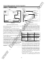
1-1 Typical Systems
The PMCS software is capable of operating on either of
two platforms:
Figure 5 shows an example of an Ethernet-based host
servicing native Ethernet devices, Modbus devices via the
Ethernet Gateway, and Commnet devices via the Modbus
Concentrator device.
I . PMCS running on a Modbus-based host PC, or
2.
PMCS running on an Ethernet-based host PC.
Determine where the PMCS will be based using the
following flowchart:
an
tM
No
NOTE: Some types of IEDs must be wired on
dedicated private serial network segments, one
lED per serial Modbus line. Figure 2a illustrates
this configuration. The IEDs that require
dedicated Modbus segments are the EPM 9650Q�
EPM 3720, ML PQM, and EPM 7330.
lP
ar
Base PMCS on Modbus.
tri
ca
After you determine the appropriate base (Ethernet or
Modbus) for the PMCS software, the general network
architecture will fall into one of the forms illustrated in
Figures I through 4. These figures offer samples of various
network architecture configurations possible with PMCS.
Ethernet
Mod bus
Protocols Uti l i zed
Figure I
Figure 4
Figure 5
Mod bus
Direct
./
Commnet
./
./
./
./
./
./
./
./
./
./
./
.E
Figure 2
Figure 3
Modbus
via
Ethernet
lec
Ethernet
Direct
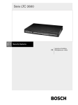
Figure 2. Commercial Ethernet and Modbus network.
w
As the above table shows, Modbus RTU is required in all
instances, whether it is being used as a stand-alone
network, supporting commnet IEDs, or serving as a slave to
an Ethernet-based host.
Figure I presents the Power Management Control System
operating on a Modbus-only network.
ww
Figure 1. Modbus-only network.
3
.c
om
Power Management Control System
-
Introduction
ua
ls
Chapter 1
tM
an
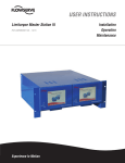
Figure 2a. Substation Ethernet and Modbus network.
Figure 5. Ethernet-based host services Ethernet, Modbus,
and commnet networks.
1-2 Master-Slave Organization
ar
Figure 3. Modbus and commnet network.
lP
The PMCS in either a Modbus-host or an Ethernet-host
configuration is a master.,slave network. The host is
considered to be the master, with the attached networks of
IEDs serving as its slaves.
ca
This relationship means that the communications are
always initiated at the host; an IED will not speak without
being asked to. The master requests information, the slave
replies.
lec
tri
The PMCS DDE Server receives a request from a client
application for some data, perhaps a relay waveform
capture. The Server routes the request to the correct IED,
the lED replies to the Server, and the Server passes the
information back to the client that originally requested it.
For further details, refer to the PMCS Network and Device
Configurator DDE Server User's Guide, GEH-651 0.
Commnel dev1ces
ww
w
.E
Figure 4. Ethernet, Modbus, and commnet network.
4
.c
om
Power Management Control System
Chapter 1
-
Introduction
Ethernet Network Card
Several pieces of hardware are required to build a network
based on PMCS. They are the host computer and the
network interface card, each of which is described below.
Once the host computer is operating and its interface card
is installed, it is time to attach the power management
IEDs to the network. These IEDs are described in Section
1-8.
The Ethernet network card provides the interface between
the host PC and the Ethernet network. With the host
communicating over Ethernet, another interface is
required to communicate with RS-485 networks, where
most power management IEDs reside. (Some recent power
management IEDs, such as the EPM 7700, have built-in
Ethernet capability. Install these devices using standard
Ethernet networking procedures.)
Host Computer
This interface between Ethernet and RS-485 is provided by
the Ethernet Gateway. See Section I -4 for more
information on Ethernet, and Section I- I, Figures 2 and
4, for examples of how the Ethernet Gateway is used to
integrate RS-485 networks into the Ethernet network.
ua
ls
1-3 Required Hardware
Primary user interface
•
Data collection, storage, and retrieval
•
Event reporting with time and date stamp
•
Energy calculations and trending
•
Network lED status
•
Alarming and reporting
1-4 Compatibil ity & Interconnection with Existing
Ethernet Networks
tM
Communication management
•
PMCS and the Ethernet Gateway require TCP/IP to be
installed on the host computer. The drivers for the
TCP/IP protocol are included with Windows 2000 SP2,
which is required to run PMCS, so any customer running
PMCS should have these drivers available.
ar
•
an
The heart of the PMCS is software running on a host PC.
Regardless of whether the host PC is based on an Ethernet
or Modbus network, its functions include the following:
lP
The minimum requirements for the host PC are presented
in GEH-65 I 4, Read This Book First.
ca
The communications interface is the connection between
the host PC and the network of IEDs. Your host will
require either an Ethernet communications card, an RS485 communications card, or an RS-232/RS-485 converter.
An Ethernet-based host PC requires an Ethernet network
card. A Modbus-based host PC requires an RS-485
interface card or an RS-232/RS-485 converter. These are
described below.
1-5 Operation During Power Outage
tri
PMCS will not lose any data in the event of a power outage;
however, communications will be interrupted until power
is restored.
Should control power to a Modbus Concentrator be lost,
PMCS will be unable to communicate with any commnet
IEDs downstream from the Concentrator until power is
restored. No data will be lost, but communications will be
interrupted.
lec
RS-485 Interface Card or RS-232/RS-485 Converter
The RS-485 interface card provides the interface between
the host PC and the Modbus network and terminates the
network at the host computer. This standard RS-485
interface card provides eight RS-485 ports. PMCS supports
up to 256 RS-485 communication ports. See Sections 2-1,
2-4, and 2-7 for more details on using multiple RS-485
networks with PMCS.
.E
The same is true of the Ethernet Gateway; as the linchpin
connecting the host to the network of IEDs, if a Gateway
loses control power, the host will be unable to
communicate with any IEDs attached to the Gateway until
power is restored.
For more modest needs, a single RS-485 network can be
provided by an RS-232/RS-485 converter, a self-contained
lED that converts signals between RS-232 and RS-485. This
lED plugs into the RS-232 port on the back of the host PC
and is less expensive than an RS-485 interface card.
You can avoid this situation by providing uninterruptable
power supplies (UPS) to the host computer and by
providing secure control power to the IEDs, either with
UPS systems or battery backups (different IEDs have
different requirements). Refer to individual user guides
for information on control-power requirements.
w
ww
Consult your IAN personnel or system integrator for
information on integrating PMCS with an existing
Ethernet-based network.
5
.c
om
Power Management Control System
Chapter 1
-
Introduction
1-6 Time & Date Stamping
ua
ls
PMCS stamps each event with a time and date code for
precise reference. The time and date are set by the DDE
Server and passed across the network to each lED, so that
all IEDs are synchronized.
an
Additionally, some PMCS IEDs support IRIG time
synchronization. If IRIG is used in a PMCS system, it is
recommended that the host PC be IRIG time synched as
well to maintain synchronization between the IEDs and
the PMCS DDE Server.
ca
lP
An example of this scenario is shown in Figure 5.
ar
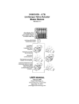
PMCS also offers the ability to use modems to reach across
wide areas to remote facilities or substations. For instance,
you could use PMCS at a central location to collect power
management data from IEDs in a factory, warehouse, or
substation in another state or control the lights, air
conditioning, or protective relays in your facility from
across the country.
tM
1-7 Remote System Operation
I
I
lec
tri
Radio Frequency transmission,
Fiber optic connection,
Leased line
a phone line connection
Figure 6. Example of remote operation using modems.
.E
56kbps phone modems, radio frequency (RF) modems,
and fiber optic modems (FOM) may be used with PMCS.
w
While it is possible to use dial-up lines to connect to distant
RS-485 networks, the vagaries of the phone system and the
excessive long-distance charges preclude using this as a
twenty-four-hour-a-day connection. Leased lines dedicated
to this purpose provide a viable alternative to a constant
long-distance telephone connection.
ww
For further information on using modems for long-range
operation of PMCS, contact your GE sales representative.
6
.c
om
Power Management Control System
Chapter 1
1-8 Supported l EOs
-
Introduction
ua
ls
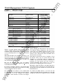
protocol, and maximum communications speed for
Modbus-based
IEDs
(Commnet
IEDs
must
communicate through the Modbus Concentrator).
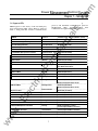
PMCS supports a wide variety of GE and third-party
power management IEDs. These IEDs are listed in
Table 1, along with their function, communications
Function
Communications Protocol ( Modbus Speed)
239 Motor Protection Relay
Protection/Control
Modbus RTU (19.2 Kbaud)
269 Plus Motor Management Relay
Protection/Control
Modbus RTU (2400 baud)
565 Feeder Management Relay
Protection/Control
735 Feeder Relay
Protection/Control
GE-Zenith Generator PLC (Series 90-70)
Metering/Control
GE-Zenith MX200 (Microprocessor Controller)
Protection/Control
Modbus RTU (19.2 Kbaud)
EPM 7330
Metering
Modbus RTU (19.2 Kbaud)
EPM 3710 Meter
Metering
Modbus RTU (19.2 Kbaud)
EPM 3720 Meter
Metering
Modbus RTU (19.2 Kbaud)
Metering
Modbus RTU (19.2 Kbaud)
Metering/Control
Modbus RTU (19.2 Kbaud)
Modbus RTU (9600 baud)
Modbus RTU (19.2 Kbaud)
tM
Modbus RTU (19.2 Kbaud)
ar
EPM 7300 Meter
lP
EPM 7700 Meter
EPM 5000P Meter
EPM 5300P Meter
EPM 5350P Meter
Modbus RTU (9600 baud)
Metering
Modbus RTU (9600 baud)
Metering
Modbus RTU (9600 baud)
Metering
Modbus TCP (Ethernet 10BaseT, RJ-45)
Metering/Control
Modbus RTU (38.4 Kbaud)
lec
tri
EPM 9450Q Meter
Note: Native Ethernet device.
Metering
ca
EPM 5200P Meter
EPM 9650Q Meter
an
lED Name
Modbus TCP (Ethernet 10BaseT, RJ-45)
Metering/Control
Modbus RTU (38.4 Kbaud)
Modbus TCP (Ethernet 10BaseT, RJ-45)
Protection/Control
GE Fanuc PLC 90no
Protection/Control
Modbus RTU (19.2 Kbaud)
GE Fanuc PLC Micro 90
Protection/Control
Modbus RTU (19.2 Kbaud)
Universal Relay
Protection/Control
Modbus RTU (19.2 Kbaud)
MicroVersaTrip-C and -D Trip Units
Metering/Protection
commnet (requires Modbus Concentrator)
Modbus Concentrator
Communications
Modbus RTU (19.2 Kbaud)
POWER LEADER Electronic Power Meter
Metering
Modbus (19.2 Kbaud) or commnet
.E
GE Fanuc PLC 90/30
Modbus RTU (19.2 Kbaud)
(commnet requires Modbus Concentrator)
Communications
commnet (requires Modbus Concentrator)
POWER LEADER Repeater
Communication
commnet (requires Modbus Concentrator)
Power Quality Meter (PQM)
Metering
Modbus RTU (19.2 Kbaud on 1 or 2 ports)
ww
w
POWER LEADER J unction Box
7
--
w
ww
.E
tri
lec
an
tM
ar
lP
ca
ua
ls
.c
om
Chapter 1
-
Introduction
.c
om
Power Management Control System
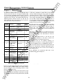
Function
Communications Protocol ( Modbus Spee d )
RS-485 Repeater
Communications
Modbus RTU (19.2 Kbaud)
369 Motor Management Relay
Metering/Control
Modbus RTU (19.2 Kbaud)
EPM 7500 Electronic Power Meter
Protection/Control
Modbus RTU (19.2 Kbaud)
EPM 7600 Electronic Power Meter
Protection/Control
Modbus RTU (19.2 Kbaud)
Motor Manager II (MMII)
Protection/Control
Modbus RTU (19.2 Kbaud)
EPM7430D/EPM7450D (Futura)
Protection/Control
Modbus RTU ( 9600 baud)
Spectra Electronic Control Module
Protection
commnet (requires Mod bus Concentrator)
Spectra MVT for GEK Frame MCCB
Metering/Protection
SR469 Motor Management Relay
Protection/Control
SR489 Generator Management Relay
Protection/Control
SR745 Transformer Management Relay
Protection/Control
SR750 Feeder Management Relay
Protection/Control
Modbus RTU (19.2 Kbaud on 1 or 2 ports)
SR760 Feeder Management Relay
Protection/Control
Modbus RTU (19.2 Kbaud on 1 or 2 ports)
POWER LEADER MDP Overcurrent Relay
Protection
Modbus (19.2 Kbaud) or commnet
POWER LEADER Modbus Monitor
Monitoring
Modbus RTU (19.2 Kbaud on 1 or 2 ports)
POWER LEADER Meter
Metering
commnet (requires Modbus Concentrator)
an
ua
ls
lED Name
commnet (requires Modbus Concentrator)
Modbus RTU (19.2 Kbaud on 1 or 2 ports)
Modbus RTU (19.2 Kbaud on 1 or 2 ports)
ar
tM
Modbus RTU (19.2 Kbaud on 1 or 2 ports)
lP
(commnet requires Modbus Concentrator)
w
.E
lec
tri
ca
Table 1 . l EOs supported by P MC$.2
ww
2 The POWER LEADER Ethernet Gateway is not listed in Table
PMCS resides on the Ethernet level.
I. The Ethernet Gateway is an alternate host for the RS.485 networks used when the
8
w
ww
.E
tri
lec
an
tM
ar
lP
ca
ua
ls
.c
om
.c
om
Power Management Control System
Chapter 2
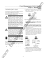
Chapter 2 - Network Design
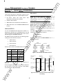
This
section
describes
how
to
design
a
Power
Management Control System network on paper so that
will proceed smoothly.
You need two things for this exercise: a complete list of
the IEDs to be networked and a diagram or map of
where the IEDs will be located, preferably with realistic
distances noted so that wiring runs may be kept within
an
the appropriate limits.
Using the list of IEDs to be networked, refer to Table
I
and note which communications protocols are required
(commnet or Modbus). For Modbus IEDs, note the
communications speed at which each lED operates. For
tM
IEDs supporting both protocols, you will need to decide
which protocol will be used. Generally, it is preferable to
use Modbus rather than commnet unless the Modbus
network is at or near capacity for physical IEDs.
in
hand,
ar
When the list of IEDs and the floor plan are
w
.E
lec
tri
ca
lP
proceed to Section 2-l for network design rules.
ww
Network Desig n
ua
ls
actual construction and configuration of the network
-
g
w
ww
.E
tri
lec
an
tM
ar
lP
ca
ua
ls
.c
om
.c
om
Power Management Control System
Chapter 2
-
Network Desig n
2-1 Modbus Rules
The most basic network configuration for PMCS assumes
that the software is running on a host PC supporting one
or more RS-485 networks on the Modbus protocol. (See
Figure I for an example ofthis configuration. )
ua
ls
Table 2 explains the configuration rules for PMCS
networks based on the Modbus platform. Commnet IEDs
may be integrated through the Modbus Concentrator (see
Table 4 for commnet wiring rules ) .
Follow these rules for the
host. . .
And these rules for the attached Modbus network(s) ...
Modbus
I.
I.
Each Modbus network supports up to 3 I physical Modbus IEDs
and up to 247 Modbus addresses. This is possible because
commnet IEDs attached to Modbus Concentrators occupy
Modbus addresses but do not create an electrical drain on the RS485 network and thus are not counted as physical Modbus IEDs.
2.
Each Modbus network must be properly terminated at each end
of the network. See Section 2-4.
tM
Maximum cable length of each Modbus network is 4000 feet. (See
notes on using repeaters to increase this range, Section 2-4. Also,
see the note regarding substation installation in Chapter 3. )
ar
All Modbus IEDs attached to a single RS-485 network must
communicate at the same baud rate. (See Table I for Modbus
IEDs' communication speeds. )
RS-485 cable shields must be properly grounded. For maximum
protection against surge and EMI damage, each lED on the
network should have an isolated ground connection. See Section
2-4, Modbus rule 4, for an example of proper RS-485 wiring and
grounding. Also, see the note regarding substation installation in
Chapter 3.
The host PC must be
located at one end of the
Modbus network(s ).
ca
3.
3.
The Modbus networks are
connected to the host PC
via an eight-port RS-485
4.
communications card.3
An option for more
limited systems is an RS232/RS-485 converter,
5.
which permits a single RS4
485 network.
lP
2.
The host PC can support
up to 256 independent
Modbus networks. The
actual number is
determined by the
communication cards
installed in the host PC
(see below).
an
Host PC is
based on:
3
lec
tri
Table 2. Host PC configuration rules.
The following RS-485 interface card is recommended for providing the R�5 connection at the host PC. I f any other serial card is used, PMCS
requires that the communications driver be compatible with the
MS Windows serial communications protocol. Please refer to Section 3-1 for
.E
information on the special termination requirements of the R�5 card.
Manufacturer
Description
Connect Tech, Inc.
lntellicon-Fiex8 RS-485 card
Intellicon/DFLEX SUM
8 Port, DB9 1/0 Box
I
4
Part, Order N um ber
1 4808064XXNC
SIMMS
IOB08DB9
The following RS-232/RS-485 converter is recommended for providing a single RS-485 connection at the host PC.
w
4
Quantity/8 ports
Manufacturer
Description
Part, O rder N umber
Multilin
RS-485/RS-232 Converter
F4851 20
ww
When using the above RS-232/RS-485 converter, remember that the converter has DIP switches inside that determine its baud rate. Switch group 3
should be set according to the baud rate at which the converter is to be used. Refer to the converter's documentation for further information.
10
w
ww
.E
tri
lec
an
tM
ar
lP
ca
ua
ls
.c
om
.c
om
Power Management Control System
Chapter 2
2-2 Ethernet Configuration Rules
-
Network Desig n
EPM 7700 devices require a separate network
configuration beyond connecting the devices to the
Ethernet IAN. Please refer to the following PMCS
technical
documentation
for
complete
network
configuration rules and guidelines:
Recently, IEDs with built-in Ethernet support have begun
to become available; PMCS is also capable of supporting
these devices. Examples of such devices are the EPM 7700
meter and EPM 9450Q I 9650Q meters. These devices
reside on the Ethernet network at the same level as the
Ethernet Gateway.
GEH-65 1 4, PMCS Read-This-BookFirst. Refer to the section
titled "Configuring the EPM 7700 Device Network."
an
DEH-4003 5, GE 7700 Gateway User's Guide. Refer to the
section titled "EPM 7700 Network Configuration."
EPM9450Q and EPM9650Q devices require separate
network configuration beyond connecting the devices to
the Ethernet IAN. Refer to the instruction manuals of
these devices and to the sections titled "Internal Network
Option." Also refer to DEH-65 1 0, DDE Server User's Guide.
Refer to the sections describing the use and configuration
of the Modbus TCP Server.
ww
w
.E
lec
tri
ca
lP
ar
tM
Table 3 explains the configuration rules for PMCS
networks based on the Ethernet platform. Commnet IEDs
may be integrated through the Modbus Concentrator.
(See Table 4 for commnet wiring rules. )
ua
ls
It is also possible to run the PMCS on a host PC operating
on an Ethernet network. If PMCS is running on an
Ethernet-based PC, an Ethernet Gateway is required to
communicate with the attached Modbus network( s ) . (See
Figure 2 for an example of this configuration. )
11
w
ww
.E
tri
lec
an
tM
ar
lP
ca
ua
ls
.c
om
.c
om
Power Management Control System
Chapter 2
-
Network Desi g n
Host PC is
based on:
Follow these rules for the host...
Ethernet
1.
Ethernet Gateway (s) must be used to
communicate with non-Ethernet IEDs.
Ethernet-capable IEDs may be installed
directly on the Ethernet network at the
same level as the Ethernet Gateway (s ) .
2.
The host PC supports up to 64 Ethernet 2.
Gateways.
Each Modbus network must be properly terminated
at each end of the network. See Section 2-4.
3.
Each Ethernet Gateway supports up to
four independent Modbus networks.
The EPM 9450Q /9650Q devices will
support one Modbus network.
3.
The Ethernet Gateway must be located at one end of
the Modbus network( s ) .
4.
Maximum cable length of each Modbus network is
4000 feet. (See notes on using repeaters to increase
this range, Section 2-4. Also, see the note regarding
substation installation in Chapter 3. )
Ethernet networks should conform to
the design guidelines described in
Section 2-3.
6.
ca
Table 3. Ethernet configuration rules2-3 Ethernet
Network Considerations
lec
tri
This section describes some of the specifications which
must be considered when designing an Ethernet network
to be used with PMCS.
Note: These specifications are guidelines only and should
.E
not be used for actual network design. Consult with a
qualified LAN engineer for design requirements that meet
your specific installation. The complete specifications are
listed in IEEE 802.3 Ethernet. In addition, the National
Electrical Code (NEC ) and all applicable local codes must
be followed for installing wiring.
w
Ethernet supports four physical media: lOBase-2
(thinnet), I OBase-5 (thicknet ) , l OBase-T (twisted pair ) ,
and I OBase-FL (fiber ) . l OBase-T is most common.
ww
ua
ls
an
Each Modbus network supports up to 3 1 physical
Modbus IEDs and up to 24 7 Modbus addresses. This
is possible because commnet IEDs attached to
Modbus Concentrators occupy Modbus addresses
but are not seen as physical Modbus IEDs.
tM
The actual number of IEDs supported
by the host varies from system to system,
depending on the variety of IEDs used
5.
and the number of PMCS data tags
required by the IEDs. See GEH-6509,
PMCS DDE I nterface Guide, for details.
lP
5.
1.
All Modbus IEDs attached to a single RS485
network must communicate at the same baud rate.
(See Table I for Modbus IEDs' communication
speeds. )
ar
4.
And these rules for the Modbus networks attached to the
Ethernet Gateways ...
12
RS485 cable shields must be properly grounded. For
maximum protection against surge and EMI
damage, each lED on the network should have an
isolated ground connection. See Section 2-4,
Modbus rule 4, for an example of proper RS485
wiring and grounding. Also, see the note regarding
substation installation in Chapter 3.
w
ww
.E
tri
lec
an
tM
ar
lP
ca
ua
ls
.c
om
.c
om
Power Management Control System
I OBase-T is specified when twisted pair is used and I OBase
FL is specified where fiber optic cable is used. While media
converters are available to allow the use of both twisted
pair and fiber optic cable in the same LAN, and can be
used to extend the length of the LAN, they are beyond the
scope of this discussion.
A lOBase-T LAN can have a maximum of 1 021 devices
connected.
Use of repeaters, routers, bridges, gateways, etc.
Repeaters may be used to connect LAN segment�. and do
not determine the boundaries of the LAN. They are used
to extend the LAN beyond a single segment. Routers,
bridges and gateways may be used to connect the LI\J'� to
other LANs or to a WAN.
10Base-FL specifi cati ons and rul es
Maximum/Minimum length of segments
For a 1 OBase-FL LAN, the maximum length of a segment is
2000 meters (6500 ft). The minimum length of any cable
is 2.5 Meters or about 8 ft. This minimum length is of
particular concern when a device is located in close
proximity to the hub.
tM
CAUT I O N : The recommended installation
practice is to implement optical fiber for
connections between buildings to provide
electrical isolation. This eliminates harmful
ground loops caused by differences in the
ground potential between structures.
Network De� n
ua
ls
7700 with Xpress card directly uses either of two types of
Ethernet physical media that must be specified when
ordering the meter, lOBase-T, or lOBase-FL EPM 9450Q
and EPM 9650Q must be ordered with I 0 Base-T Ethernet
Option. The meters operate in a I 0 Mbps system.
-
an
NOTE for EPM 7700 and 9450Q and 9650Q: The EPM
Chapter 2
Maximum number of segments
ar
A 1 OBase-FL LAN can consist of up to 5 segments using 4
repeaters. However, only three of these segments can have
devices connected.
tri
ca
lP
CAUT I O N : Data line surge protection is
recommended for network components such as
hubs, computers, or moderns connected to IEDs
with copper wire, especially installations where
the data communication cable is exposed (i.e.,
not encased in conduit ) or runs parallel to power
conductors. PMCS IEDs are routinely installed in
areas exposed to heavy electromagnetic fields
(EMF), which can induce damaging surges in
data communication lines. Data line surge
protection is not required for fiber optic
connections.
lec
10Base-T specifications and rules
lOBase-T Ethernet uses CAT 3, 4 or 5 twisted pair cable,
depending on the installation.
Maximum/Minimum length of segments
For a lOBase-T LAN the maximum length of a segment is
100 meters (328 ft ) . The minimum length of any cable is
2.5 Meters or about 8 ft This minimum length is of
particular concern when a device is located in close
proximity to the hub.
.E
,
Maximum number of segments
w
A I OBase-T LAN can consist of up to 5 segments using 4
repeaters. However, only three of these segments can have
devices connected.
ww
Maximum number of devices
13
Maximum number of devices
A l OBase-FL LAN can have a maximum of 1 024 devices
connected.
Use of repeaters, routers, bridges, gateways, etc.
Repeaters may be used to connect segments and do not
determine the boundaries of the LAN They are used to
extend the LAN beyond a single segment. Routen, bridges
and gateways may be used to connect the LAN to other
LANs or to a WAN.
.
w
ww
.E
tri
lec
an
tM
ar
lP
ca
ua
ls
.c
om
.c
om
Power Management Control System
Chapter 2 - Network Desi g n
2-4 Comrtmet Configuration Rules
POWER LEADER commnet IEDs may be integrated into a
PMCS network through a special Modbus lED called the
ua
ls
Modbus Concentrator. The rules outlined in Table 4 apply
to using commnet IEDs with PMCS, regardless of whether
the host PC is operating on an Ethernet or Modbus
network. (See Figures 3 and 4 for examples of commnet
IEDs operating on PMCS. )
Conmmet lED configuration rules:
Modbus
I.
Each Modbus Concentrator supports up to eight commnet segments.
Figure 1 5
Concentrator
2.
Each commnet segment supports up to four commnet IEDs.
Figure 1 5
3.
4.
Only one waveform-capturing meter (POWER LEADER Meter) is a llowed per
No figure
provided
POWER LEADER Repeaters and Junction/Outlet Boxes do not count toward the
four-lED-per-segment limit.
Commnet
I.
ar
No connections between commnet segments are permitted. Each segment must
Figure 20
Figure 28 -
connected to the Concentrator at one point only (no loops permitted ) .
Figure 32
Maximum cable length of a commnet segment is I 000 feet. Maximum range
wiring
between commnet IEDs on a segment is I 000 feet (except for repeaters; see
limitations
below ) .
In no case may a commnet lED be wired more than I 000 feet from the Modbus
ca
2.
Figure 1 9 and
be wired independently (having no contact with other commnet segments) and
lP
5.
Reference
Figure:
commnet segment.
tM
limitations·
an
Rules
regarding:
Figure 1 6
Figure 1 6
Concentrator or a POWER LEADER Repeater.
3.
POWER LEADER Repeaters may be used to extend the range of commnet
Figure 1 7
segments. A repeater regenerates the commnet signal to its original strength,
4.
tri
allowing it to travel up to another I 000 feet.
lDng-distance segments may be created by placing multiple repeaters adjacent to
Figure 1 8
one another in a commnet segment. A repeater communicating directly with
lec
another repeater may span up to 0000 feet.
5.
No figure
provided
For ease and economy of wiring, the POWER LEADERJunction/Outlet box may
be used to create nodes of commnet IEDs with a common wiring point to be
Figure 19 and
connected to the Modbus concentrator. The POWER LEADER Junction/Outlet
Figure 20
.E
6.
Maximum allowable cable length of a single commnet segment is 1 2,000 feet,
which may be constructed with any allowable combination of repeaters and IEDs.
Box allows the interconnection of as many as four shielded, twisted-pair cables to
create this common wiring point. For instance, rather than a daisy-chain of
wiring in a lineup from one meter or trip unit to the next, up to four IEDs may be
wired to the POWER LEADER Junction/ Outlet Box, which is then connected to
ww
w
the Modbus Concentrator.
Table 4. Commnet l ED configuration rules.
14
w
ww
.E
tri
lec
an
tM
ar
lP
ca
ua
ls
.c
om
.c
om
Power Management Control S_ystem
Chapter 2
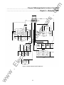
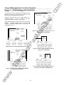
1.
2-5 Modbus Wiring Ru les - Diagrams
Each RS-485 network may support up to 3 1 Modbus
IEDs. Figure 7 illustrates this rule. (See the
exception below Figure 6. )
This section describes in greater detail the rules you must
follow when designing a Modbus network.
3 1 RS-48 5 1 E D s maximum;
PMCS Host PC, Ethernet Gateway or MSP
of Modbus network.
an
always located at one end
Figure 7. Network illustrating Modbus Rules 1 and 2.
Exception to Rule 1: Some types of IEDs must be
wired on dedicated private serial network segn1ents,
one lED per serial Modbus line.
tM
WAR N I NG :
Network wiring and grounding
rules described herein apply primarily to
commercial/industrial installations. Substation
installations will exist in the presence of
dangerously elevated ground potential relative to
points outside of the station grid as well as large
electromagnetic induction fields. Additionally,
large ground faults can elevate substation
ground potentials. Follow local utility best
practices/ safety procedures to prevent risk of
shock/electrocution to personnel and damage to
equipment that could result in a loss of
protection and communications.
Network Desig n
ua
ls
The Modbus network protocol has wiring rules and limits
on the number of IEDs that may be attached.
-
The host (or Ethernet Gateway ) must always be
located at one end of any Modbus segment. It may
not be located in the center of a Modbus network.
Figure 7 shows the correct placement of the host
(PC or Ethernet Gateway ).
ar
2.
NOTE: It is important to take future
expandability into consideration when designing
a network configuration. This is particularly so
when the network is near its maximum number
of IEDs or maximum cable length. Adding I E Ds
to a network after it has been instal led may
require rewiring the network.
ca
lP
3.
tri
CAUT I O N : Wire-run distances mentioned in the
configuration rules assume application above
grade
or in conduit.
For below-grade
applications, refer to Section 3-- 1 , Wiring
Requirements.
lec
E I" U n 1• Urtft'
{1!1 � [)INJI!I)
tJb.aft:mrt PG'M
1 1'!1.2 1{ lHhid I
Regardless of which platform is supporting the RS-485
networks (Ethernet Gateway, RS-485 card, or RS-232/RS485 converter ), the following rules apply to each
individual RS-485 network.
OE FaUIIC f' LC U/1;1
(Ill l! � a;H.Id)
EPM 5 JQ<ll'
EPM 5 3iiOP
!19 2 K b<�•<lt
H92 K hau<ll
.E
bnucl �on
nllgU 3-.101 notwolt
bc::o rrt ct · nfit!d
Oorrtct- olll leftrrt IMUIIII tft� tn
�l lll:rt ntAS-.101 nrtwlltl
Figure 8. Network illustrating Modbus Rule 3.
4.
w
ww
All Modbus IEDs on a single RS-485 network must
communicate at the same baud rate. If IEDs with
different communication speeds are connected to
the same RS-485 network, the whole segment will
communicate at the speed of the slowest lED. Figure
8 illustrates this rule. (Communication speeds for
supported IEDs are listed in Table 1 . )
15
Each RS-485 network must be properly terminated
at both ends of the cable run after the final lED.
(See Section 3-- 1 for details on termination. ) Figure
9 illustrates this rule.
w
ww
.E
tri
lec
an
tM
ar
lP
ca
ua
ls
.c
om
Chapter 2
5.
-
Network Desi g n
Each RS485 network must have its shield properly
grounded. Figure 9 illustrates proper RS485 wiring
and grounding.
RS-485 Host
(RS-485 card•, RS 232/RS-485 converter,
Network Connections:
ua
ls
at host
12 0-ohm termina:ing resistor
RS-485
• Connect TechRS-485 cards
requi'e a 600--ohm resisto1
Two wire, twisted,
in place of the 120-ohm
shielded pair cable
#t
an
RS·485 lED
terminating resistor.
tM
Follow the cable to the next lED, and repeat the
above procedure. Do not connect the RS485 shield
from the previous lED, but DO connect the RS485
OUT shield on its way to the next lED.
S hield
connected
Multiple Serial Port or Ethernet Gateway RS-485 port)
CAUT I O N : Improper grounding may create a
condition
ground-loop
and
cause
communications failures. Make sure you follow
the wiring diagram carefully.
To ensure proper grounding, follow this procedure.
Begin by grounding the RS485 cable shield at the
.host. Follow the cable to the first lED on the
network. Do NOT connect the cable ground to the
. lED. Pick up the RS485 output cable from the lED
and attach its ground to the lED's shield connection
or grounding screw. For IEDs with no grounding
connectors, connect to earth ground.
.c
om
Power Management Control System
ar
RS-485 1ED
Shield n ot
Sheld
connected
at first lED
RS-485 OUT
Shield not
#2
connected
---T---
lP
EXCEPT I O N :
The
Multilin
565 Feeder
Management Relay does not have isolated
communications ports. Do NOT connect the
shield at this lED. Instead connect the shield of
the incoming RS485 cable to the shield of the
outgoing RS485 cable, skipping the Multilin 565.
ailED
/ RS-485 1N
.____ '---
Sheld
connected
at l E D
ca
RS-485 OUT
tri
Rules of thumb: RS485 cable ground should always be
connected at the previous lED, never upon arrival at
an lED. All RS-485 IEDs must have either two
communications
cables
attached
or
one
communications cable and a terminating resistor.
Shield not
connected
lec
ailED
1--+---i--- 1 � S-485 1N
12Q..ohm
.E
termin ati1g resistor
Figure 9. N etwork illustrating Modbus Rules 4 and 5.
ww
w
6.
16
A single RS-485 network may have up to 2 1 5
commnet IEDs attached to it via POWER LEADER
Modbus Concentrators. Figure 10 illustrates this
rule.
w
ww
.E
tri
lec
an
tM
ar
lP
ca
ua
ls
.c
om
.c
om
Power Management Control System
Chapter 2
9.
NetWQ!�_Qesig n
There may be no more than two RS-485 repeaters
between any two RS-485 IEDs. Figure ! 3 illustrates
this rule.
ua
ls
RS-4851EDs
-
Correct- Maximum two repeaters between RS-485 lEDs
Commnet lEOs
(up to 32 per Modbus Concentrator,
2 1 5 total per RS-485 network)
Incorrect - m ore than 2 repeaters between RS-485 1 £: [' :
A single RS-485 network may have no more than
4000 feet of cable (total cable length, not distance
between IEDs ). Figure I I illustrates this rule.
lP
Total Cable Length < 4000 fe et
ca
1500 ft
Figure 1 1 . N etwork illustrating Modbus Rule 7.
tri
RS-485 repeaters may be used to extend the range
beyond 4000 feet. A single RS-485 repeater may be
used to provide a 4000-foot extension, and each
additional repeater in a sequence extends the range
1 2 illustrates this rule.
.E
lec
by another 4000 feet. Figure
1 0.
Modbus Monitors (dual-port version ) may not be
wired in any configuration other than the four
shown in Figure I 4. Although the Monitor's RS-485
ports have separate addresses, you may NOT wire
the same Modbus network to both ports. A two-port
Modbus Monitor must be wired to two separate
Modbus networks.
------------
NOTE: For more information on wiring the
POWER LEADER Modbus Monitor, refer to
DEH-027, Modbus Monitor User's Guide.
-----
RS -485
With 2 Repeaters,
ft
Figure 1 2. N etwork illustrating Modbus Rule 8.
w
ww
However, the Modbus Monitor's wiring scheme is
slightly different from the Multilin scheme. The
dual-port version of the POWER LEADER
Modbus Monitor MUST be connected to two
separate RS-485 networks. See Rule 1 0 for details.
-------
Total Cable Length < 8000 feet
2500
NOTE O N DUAL-PO RT RS-485 l E OS :
Several of the Multilin power management IEDs
offer two RS-485 ports on the same lED. Do not
connect both RS-485 ports to a PMCS network. The
same data are available from both RS-485 ports
and will cause conflicts if the PMCS attempts to
access both ports simultaneously.
ar
RS-485 lEOs
8.
------- -------------
tM
7.
an
Figure 1 3. N etwork illustrating Modbus Rule 9.
Figure 1 0. N etwork illustrating Modbus Rule 6.
17
w
ww
.E
tri
lec
an
tM
ar
lP
ca
ua
ls
.c
om
.c
om
Power Management Control System
-
Network Desi g n
Example A
ModJus
Segnent A
Example B
ModJus
Segnent A
rrnl
�
,�
Example C
Example D
ModJus
Segnent A
ModJus
Segnent B
tM
an
ModJus
Segnent A
makes this concern irrelevant for examples A, B,
and D, since in Example A you could have either
a single- or a dual-port Monitor, while in
Examples B and D you may only use a dual-port
monitor ( s ) .
ModJus
Segnent B
ua
ls
Chapter 2
Figure 1 4. Valid Modbus Monitor network architectures.
lP
ar
CAUT I O N : Any other wiring of the Modbus
Monitor may result in incorrect operation and
errors.
ca
CAU T I O N D UAL P O RT M O N I TO R USERS: Do
not connect the Monitor's two RS-485 ports to the same
Modbus Segment. This will cause communication
errors and possibly damage the Monitor.
tri
Example A shows a single Modbus Monitor wired to one
Modbus segment. Example B shows the same monitor in a
dual-port version, wired to two different Modbus segments.
lec
Examples C and D illustrate fully loaded Modbus
segments. No more than two Monitors are permitted on
any Modbus segment.
.E
Example C illustrates a pair of Monitors connected to a
single Modbus segment. In this example, the Monitors
may be either single port or dual-port versions, provided
both are the same version (see note below). Example D
shows the same pair of Monitors wired to a second Modbus
segment.
ww
w
CAUT I O N : With regard to Example C (two
Monitors on a single RS-485 segment ) , it is not
permissible to mix different models of Monitors
on a segment. Monitors #l and #!2 must be of the
same model, either both single-port or both dual
port.
The nature of the other network architectures
18
w
ww
.E
lec
an
tM
ar
lP
ca
tri
ua
ls
.c
om
.c
om
Power Management Control System
Chapter 2
ua
ls
CAUT I O N : In no case may there be more than
1000 feet of cable between any two commnet
IEDs other than Repeaters. At ranges over I 000
feet, commnet signals become degraded and
communication errors may result.
ca
lP
4 commnet I E D s/segment
ar
tM
commnet segments. Each commnet segment may
support up to four commnet IEDs, only one of
which may be a waveform-capturing meter. POWER
LEADER Repeaters and Junction/Outlet Boxes are
not counted as commnet IEDs. Figure 1 5 illustrates
this rule.
For example, a segment containing a single
Repeater may have no more than 2000 feet of total
cable length. No more than 1 000 feet of cable are
permitted between the Modbus Concentrator and
the frrst Repeater or between the Repeater and the
last lED on the segment. Figure 1 7 illustrates this
rule.
an
I . Each Modbus Concentrator supports up to eight
Netwo�� Desig n
degrades and the danger of errors rises to an
unacceptable level. The Repeater regenerates a
signal to its original strength, allowing it to travel up
to another I 000 feet. Thus, each Repeater can add
up to I 000 feet of range to the commnet segment.
2-6 Commnet Wiring Rules - Diagrams
POWER LEADER commnet IEDs may be integrated into
PMCS through the use of the POWER LEADER Modbus
Concentrator, which collects data from commnet IEDs
and communicates that data across the RS-485 network.
Each Modbus Concentrator supports up to eight commnet
segments. Each commnet segment may accommodate up
to four commnet IEDs. The following are the basic rules to
ensure proper network operation for POWER LEADER
commnet IEDs. Note that these rules apply only to
individual commnet segments of a POWER LEADER
Modbus Concentrator, not to the RS-485 network.
-
tri
with one Repeater < 2000 feet
Figure 1 7. Network illustrating commnet Rule 3.
4.
Figure 1 5. Network illustrating commnet Rule 1 .
2.
Max length of a commnetsegment
A commnet segment may have no more than I 000
feet of cable between the Modbus Concentrator and
Long-distance cable runs may be built by placing two
Repeaters adjacent to one another in the segment. A
pair of adjacent Repeaters has a range of up to 6000
feet of cable. Figure 1 8 illustrates this rule.
the f"mal lED on a segment. (Repeaters may be used
16
1 000
w i th t h r e e Repeaters < 1 2 000 feet
(note: only one other l E D may be u s e d on
Figure 1 6. Network illustrating commnet Rule 2.
a c o m m n e t s e g m ent with three repeaters)
w
ww
Ma)( length of a commnet segment
Max length of a c o m m n e t s e g m e n t
Max length of a commnet segment< 1000 feet
3.
ft
with two Repeaters < 8000 f"eet
.E
lec
to extend this range; see Rule 3. ) Figure
illustrates this rule.
Figure 1 8. Network illustrating commnet Rule 4.
The maximum communication range of commnet
IEDs (including the Modbus Concentrator's
commnet ports ) is I 000 feet, after which its signal
5. The maximum allowable cable length of a single
commnet segment is 1 2 ,000 feet. This may be
19
w
ww
.E
tri
lec
an
tM
ar
lP
ca
ua
ls
.c
om
.c
om
Power Management Control System
-
achieved
Network Desi gn
with
any
allowable
combination
of
Repeaters and IEDs.
6. For
ease
of
wiring,
the
POWER
commnet IEDs with a common wiring point to be
to
the
Modbus
concentrator.
1 9 and Figure 20. Junction Boxes are net
Figure
LEADER
Junction/Outlet Box may be used to create nodes of
connected
Examples of the use of a POWER LEADER Junction
Box with the Modbus Concentrator are provided in
counted as lEDs for purposes of the four lED per
commnet segment limit. Figure
1 9 is an example of
ua
ls
Chapter 2
a Junction Box used to create a node connecting
The
four commnet IEDs to a Modbus Concentrator.
POWER LEADER Junction/Outlet Box allows the
Figure
interconnection of as many as four shielded, twisted
20 is an example of a Junction Box with
Repeaters, observing the four lED per segment limit
pair cables to create this common wiring point. This
(the two Repeaters and the Junction Box do not
can be of great help in economizing on wiring and
count as IEDs ) .
offering greater flexibility in network design. For
an
instance, rather than a daisy-chain of the wiring in a
lineup from one meter or trip unit to the next, up to
four IEDs may be wired to the POWER LEADER
Junction Box, which is then connected to the
Modbus Concentrator.
tM
to
Mod bus
CAU T I O N : The four-lED-per-segment limit must
be observed at all times. Although the POWER
LEADER Junction Box has terminals to accept
1 2 commnet lines, do NOT connect more
ar
up to
than four commnet lEDs to a single Junction
Figure 1 9. Network illustrating commnet Rule 6.
ca
lP
Box or Modbus Concentrator commnet segment.
long-range
commnet segnent
to
Mod bus
tri
C oncentator
.E
lec
Figure 20. Network illustrating commnet Rule 6.
w
ww
Concentator
20
w
ww
.E
tri
lec
an
tM
ar
lP
ca
ua
ls
.c
om
.c
om
Power Management Control System
Chapter 2
-
Network Des�
2-7 Performance Recommendations
information until it is asked by the PMCS to transmit
Although a PMCS network will function as long as all the
unevenly distributed, the Concentrator takes longer
its data to the host. If the number of commnet IEDs is
rules in the previous section are followed, you can enhance
by
considering
the
following
recommendations for Modbus, commnet.
than necessary to poll each segment.
3.
Keep data-intensity in
than
IEDs
to
a
single
Modbus
IEDs. Keep the following list in mind when selecting
per commnet segment) yields maximum performance.
which IEDs to double up on the same commnet
segment. The best choices for doubling up are listed
an
Naturally, in the real world few networks will fall into this
first.
precise configuration. To extract maximum performance
I . Spectra MicroVersaTrip trip unit
from the PMCS, follow the performance recommendations
below.
2. Enhanced MicroVersaTrip-C and -D trip units
tM
3. POWER LEADER MDP Overcurrent Relay
Modbus performance recommendations
multiple RS485 networks
4. Spectra Electronic Control Module
if possible, depending
5. POWER LEADER Electronic Power Meter
on the RS-485 connection at the host. If using an
6. POWER lEADER Meter
ar
eight-port RS-485 card or an Ethemet Gateway (four
IEDs at the top of the list are less data-intensive and
ports ) for connection to the network, you can improve
performance
by using
the
full
number
easier for the Concentrator to poll. IEDs at the bottom
of ports
of the list are very data-intensive and, if possible,
available, rather than burdening a single RS-485 port.
RS-485 ports
should be given their own commnet segment. In other
lP
Distributing the IEDs across all available
words, if you must put multiple IEDs on a segment, it is
permits the communications load to be distributed
preferable to put low-demand IEDs together on a
rather than asking a single network to carry the full
Divide the lED loads evenly
across multiple
segment and try to keep high-demand IEDs on their
own segments. Try to distribute the high-demand
ca
load.
3.
mind when connecting more
one or more segments will be supporting multiple
distributed across five Modbus Concentrators (one lED
2.
commnet
eight commnet IEDs to a single Modbus Concentrator,
Theoretically, a single Modbus lED or 40 commnet IEDs
Use
eight
Concentrator. If it is necessary to connect more than
The .Ideal Network
I.
ua
ls
performance
when distributing IEDs
IEDs across the
RS-485 networks.
available segments,
keeping the
number of high-demand IEDs per segment evenly
distributed.
Pay careful attention to Modbus Rule 2, regarding the
tri
communication speeds of IEDs on a given network.
Although a network will function with mixed IEDs, its
communication speed will be dragged down to the
2-8 Addressing the lEOs
2400-
Each lED attached to a PMCS network must have a unique
baud lED forces the entire network to communicate at
address. Prior to installing any wiring, you should plan the
2400 baud, regardless of the presence of any I 9.2-
addresses for the IEDs to avoid any conflicts. Keep in mind
kbaud iEDs.
these important points when assigning network addresses.
lec
lowest common denominator. Thus, a single
Keep a table of lED names and addresses to avoid
•
.E
Commnet performance recommendations
I.
Modbus
is
preferred over commnet
conflicts and to help with host configuration. Table
where either
protocol is available. This is the case for the POWER
LEADER Electronic Power Meter and the POWER
LEADER MDP Overcurrent Relay. Each of these IEDs
addressing
5
considerations,
Modbus Concentrator addresses must be in the
range of I to 32.
Modbus-native IEDs other than the Concentrator
may occupy any address from I to 24 7.
w
Minimize the number of commnet IEDs per segment.
The Modbus Concentrator is a polling lED, meaning
that it queries each commnet segment continuously
and in order asking for information. It then stores the
ww
Modbus
based on the following rules.
-
offers a Modbus communications option.
2.
summarizes
-
Commnet
IEDs
must
have
Modbus-equivalent
addresses in the range of 33 to 247.
The host PC does not require an address due to the
master-slave organization ofthe PMCS.
21
w
ww
.E
tri
lec
an
tM
ar
lP
ca
ua
ls
.c
om
.c
om
Power Management Control System
Network Desi gn
this mapping is: desired Modbus address + 267 commnet
address to set at I ED. For example, to set a commnet
lED to Modbus address 33, the commnet address set
at the lED must be 300. Table 6 illustrates address
mapping.
=
NOTE: Per the EIA485 standard, each RS-485
network supports up to 32 "drops" or electrical
drains on the network. However, the Ethernet
Gateway or RS-485 interface card counts as one
drop. Thus, only 3 1 other IEDs may be attached
to each RS-485 network, even though 32 Modbus
addresses are available for use. Also, unlike
commnet's POWER LEADER Repeaters, RS-485
repeaters are counted as IEDs because although
they have no Modbus address, they do act as a
drop on the network.
300
34
35
...
Appropriate Usage/Supported I EDs
.
.
.
33 - 247
33
.
-
Modbus Concentrators must have addresses
in this range
Other Modbus native IEDs may also have
addresses in this range
Modbus native IEDs may have addresses in
this range
Commnet IEDs must have addresses in this
range
-
Table 5. Mod bus address range appropriate usage.
ca
•
Because the commnet network accepts a different
range of addresses than the Modbus network,
commnet
addresses
must
be
mapped
to
corresponding Modbus addresses. The formula for
.E
w
ww
. ..
246
513
247
514
22
-!
-_j
j
_____
You may want to block commnet address assignments
by lineup and/ or Modbus Concentrator segment. For
example, start with 40 for the frrst lineup attached to
one Modbus Concentrator, 50 for the second lineup
attached, and so on. Addresses must be in the range
33 to 247. The example presented in Figun� ll\
demonstrates this.
Increment the individual IEDs in each lineup by one.
For example, if the first lED in a lineup is Modbug
address 1 0 1 , the second lED should be 1 02, the third
lED should be 1 03, etc.
Addresses may be entered or changed at any time
that control power is present.
Figure 2 1 illustrates a sample network with lED addresses;
Table 7 provides details of the IEDs shown in Figure 2 1 .
lec
•
Commnet IEDs are preprogrammed with a factory-set
address. You must change this address immediately
upon installation of the lED. Refer to the lED's user
manual for instructions on assigning an address.
tri
•
302
Table 6. Modbus-to-commnet address mapping.
Broadcast (not available to user )
lP
.
301
'l
tM
1 - 32
Set commnet I ED Address to:
ar
0
For Modbus Address:
an
Mod bus
Address
ua
ls
Chapter 2
w
ww
.E
tri
lec
an
tM
ar
ca
lP
ua
ls
.c
om
.c
om
Power Management Control Systern
Chapter 2
F
�[
I
•
I
:i: I
:�.i: 8 II�
I�
... «..�
U1
i '""'ll'
=
·=
..._,_,
. �--�
.-
l_
"'
:llll lii��
to
tn
LE LEJ
1U1t��
.,,
1ill � n��
Ul
ri 'I U
LUlU
...
I�
nwu
U,\ltl
,,.
.....l.:.
Ul
uI •;::�·
I "
I
dh���
14'
..lii!.�
"'
lP
n w:nH,ue= 1111 _.,. . ' , ..,. s• •d•�•
l.llup � l l
'""�
E-
l
..... :.
r- hll•ulut••
dh��•n
, ,
....
£iJ
tri
n 't u
U:AI U
llll ehl
i
.
atll••��
'"
.....�
"'
•u
dh1111o.:.
lUI
pu J u
...
Lr:::"
I
•••••:.:.o �IS
S 1.flallii 1
IUulpUI
...11:.:..
tn
II 111111• hlltlii Ill tl•• �niBil hll••
llliilp Ul
Figure 2 1 . Sample network with l ED addresses.
23
�
Lin i d¥1 l uhlt:111l.lll
...... , ·�·
'"
w
ww
Lf:;f'l
� Rl
��wn.:.
.E
"'
!
"
" ·=
��
t---+-:"'='=
'1:.='==---+----+-='=
= ="=-1
,
I I Lil'fl hii•J• � llk.IUI
I.IIUpUI
lec
.U
.... ���
l:
!
.ii,.hl
.
•
.. . .
i
..
ca
i
.
I
�
ar
...
1}'11
l
.,
tM
1·
an
* ....�
fnlllhtlfl
.....__ , ..
�-r----,-�--�
'�
·�
··
�
·�
"-----J
...
ua
ls
-
�-----1
1
Network �es!fl!l
_
�
'-"'
'
=
'
"
����'B\�
EJ
.. ..
-
......l. �··
-'... l
�
w
ww
.E
tri
lec
an
tM
ar
lP
ca
ua
ls
.c
om
.c
om
Power Management Control System
Chapter 2
-
Network Desi gn
Attached
Mod bus
Commnet
Equi pment
I E Ds
Address
Address
Lineup 1
Modbus Concentrator 1
001
-
Segment 1
Switchgear
POWER LEADER Electronic Power Meter
035
302
MDP Overcurrent Relay with commnet
036
303
MDP Overcurrent Relay with commnet
037
304
MDP Overcurrent Relay with commnet
038
305
POWER LEADER Electronic Power Meter
040
307
POWER LEADER Electronic Power Meter
041
308
POWER LEADER Electronic Power Meter
045
312
POWER LEADER Electronic Power Meter
046
31 3
ua
ls
POWER/VAG Medium-Voltage
Segment 2
an
Segment 3
Segment 4
MDP Overcurrent Relay with commnet
050
317
MDP Overcurrent Relay with commnet
051
31 8
052
-
'
tM
EPM 7700 Electronic Power Meter
Lineup 2
8000-Line Motor Control Center
Multilin 269 Plus Motor Relay
060
-
Modbus Concentrator 2
002
-
065
332
ar
Segment 1 - Spectra Electronic Control Module
Segment 2 · Spectra Electronic Control Module
Segment 3 · Spectra Electronic Control Module
Segment 4 · Spectra Electronic Control Module
EPM 7700 Electronic Power Meter using IP address =
070
337
085
352
090
357
n/a
n/a
3.46. 9. 1 02
Modbus Concentrator 3
lP
Uneup 3
Segment 1 - POWER LEADER Meter
Segment 2 - Enhanced MicroVersaTrip trip unit
Segment 3 - POWER LEADER Meter
Segment 4 · Enhanced MicroVersaTrip trip unit
ca
AKD-8 Low-Voltage Switchgear
Lineup S
427
432
1 65
1 70
437
1 75
442
1 80
447
1 85
452
-
Multilin 565 Feeder Management Relay
-
EPM 5300P
200
-
EPM 5200P
205
-
EPM 9650Q
210
-
EPM 7300
215
-
EPM 7330
220
-
EPM 7330
225
-
w
.E
Table 7. l E D-addressing scheme for Figure 2 1 .
ww
1 60
005
lec
Substation
422
tri
Medium-Voltage Motor Control Center
-
1 55
004
GE Fanuc Programmable Logic Controller 90/30
Lineup 4
003
24
w
ww
.E
tri
lec
an
tM
ar
lP
ca
ua
ls
.c
om
.c
om
Power Management Control System
Chapter 2
2-9 Multiple RS-485 Networks - Addressing
-
Network De�ig n
In Case Four, GHO Corp. wishes to install a PMCS power
management system using both Modbus- and comrrmet
based IEDs, with the host based on Ethernet.
Regardless of how many
RS485 networks are connected,
regarding multiple RS485
networks remain the same. Each RS485 network is
Case Five demonstrates the use of dual-port RS481) lEDs in
the
a Modbus network, showing the differences between the
addressing
concepts
Multilin
addressed independently of the others. Thus, Network I
may have an lED with Modbus address
dual-port
IEDs
and
the
POWER
LEADER
Modbus Monitor, which also provides two RS-485 pcrts.
20, and Network 2
may have an lED with Modbus address 20 without conflict.
Case Study One
The PMCS will be aware that they are different IEDs,
GHO Corp. has assigned its plant engineer, Bill, the task of
I7
A is a different address than I 7
much as the postal system delivering mail realizes that
Mulberry Lane in Town B.
designing and installing a simple power management
an
Mulberry Lane in Town
ua
ls
PMCS supports up to 256 independent Modbus networks.
system. GHO Corp. wishes to use PMCS to monitc,r and
control several Modbus power management IEDs.
2-10 System Expansion
Bill's first task is an easy one. He must choose a platform
Whenever new IEDs are added to the network, be sure to
Section I - I , he makes his decision. There is no existing
tM
on which the PMCS host will reside. Using the flowchart in
observe these points:
Follow the proper installation procedures.
•
Ensure that the system configuration rules have been
PMCS.
Next, Bill makes a list of the IEDs that GHO Corp. wants to
ar
followed.
•
Ethernet network in his facility, nor are there any plam for
one. Bill chooses Modbus as his basic platform for the
•
include on their PMCS network:
All new IEDs are shipped with the same default
•
address. To avoid conflicts, change the address of
lP
unoccupied address in the PMCS networks.
ca
2-1 1 Case Studies
Five case studies are provided as examples of how to design
called
GHO
Corp.
is
installing
a
power
tri
based IEDs that it would like to network to the PMCS
control
and
lec
remote
viewing
of power
in
Case
One
GHO Corp.
.E
In Case Three,
on
Ethernet
already
by adding some
needed.
The
Modbus
IEDs
makes a note that they should be placed on separate
RS-
required to connect the IEDs to the host PC, keeping in
has an existing
and would
now
mind that the wiring rules require him to daisy-chain the
like · to
IEDs on each RS485 network one after another. His floor
layout is shown in Figure 22.
that it would like to network to the PMCS for remote
control and viewing of power consumption and alarms.
Now, however, it wants the host to be based on Ethernet
w
are
communicate at different baud rates, though , and Bill
needed. He maps where his IEDs must be located and
GHO Corp. still has only a few Modbus RTU-based IEDs
Modbus, which requires the use
of an
Ethernet Gateway.
ww
Concentrators
where the host PC will sit. He measures the cable runs
integrate a power management system with this network.
rather than
I
wiring could be run and how many feet of cable will be
commnet IEDs to the network.
network based
One Multilin 565 Feeder Management Relay for
feeder protection
Bill now turns to his floor layout to see just where the
In Case Two, GHO Corp. wishes to expand the Modbus
developed
One Multilin 269+ Motor Relay for motor protection
•
485 networks for improved performance.
consumption and alarms.
network it
Three EPM
because no commnet IEDs are being used, no Modbus
In Case One, GHO Corp. has only a few Modbus RTU
for
3 720 Meters for monitoring power
•
•
and notes that all of the IEDs communicate on Modbus;
management system based on PMCS.
software
90/30 Programmable Logic Cont.>·oller for
He checks the list of communications protocols in Table
a network based on PMCS. In each case, a fictitious
company
One PLC
process control
each new lED immediately upon installation to an
25
w
ww
.E
tri
lec
an
tM
ar
lP
ca
ua
ls
.c
om
.c
om
Power Management Control System
N_
et_w_o_rk_
D_
e s__ig.._
_
C_
ha__._p_te_r_2_-_
__, n_________________________
_
RS485 networks
tenninated at host PC
lathe Area
Network 4 - 1 9 . 2 kbaud
E P M 3720
350'
]35&'
_
�
----
I
ua
ls
Electronic Power Meter
Millilg Area
60U
350'
•Feeder Management Relay
Main pcwer feed
Multlin 565
EPM 3720
Electronic Power Meter
�.!
550'
55U
Multilin 269+
PLC 90/30
Motor Relay
Programmable logic C onboller
Assembly Lfle Area
600,
Multilin 269+
Motor Relay
Termilating
network wiring diagram
PLC 90/30
Programmable Logic C o ntroller
short of the 4000-foot limit.
network wiring diagram
ar
met, Bill moves on to select Modbus addresses for the !EDs.
He checks Section 2-7 and sees that he can assign his IEDs
any Modbus address between
l
and 247.
He select:,'
addresses and records them for future reference. Tbc
RS-485 card by attachingjumpers to
address chart is shown in Table 8.
lP
the correct pins (see RS-485 card user manual ) . The
--
appropriate terminating resistors must be used at the
ca
RS-485 network, per Section 2-4, rule
His cable length is well under the 4000-foot limit, so no
Because he has only six IEDs to connect, only one
RS-485
tri
network is required, and thus an RS-232/RS-485 converter
would do the job. However, he considers the performance
recommendations given in Section 2-6 and, remembering
his earlier note about the different baud rates of his
l ED Type
Physical Location
PLC 90/30
Assembly line
01
EPM 3720
Milling
02
EPM 3720
Lathe area
03
EPM 3720
Machining
04
Multilin 269+
Assembly line
05
Multilin 565
Power intake area
06
lec
RS-485 network card, so that he can place lEDs
with matching baud rates on the same RS-485 network.
The system redesigned for optimum performance is shown
ww
w
.E
in Figure 23.
--·�
--l
-�·!
Modbus Address
Table 8. 1 E D Addresses for Case One.
Modbus lEDs, he decides to distribute the lEDs across four
ports of an
'
Confident that his new design will provide maximum
Proper termination is required at each end of the network,
repeaters will be needed.
-----
performance, and with his wiring requirements and limit�
Next, Bill checks Table 2 for the Modbus wiring rules.
3.
-
·
I
I
I
tM
Bill's calculates his total cable length at 2300 feet, well
opposite end of each
1
Figure 23. Redesigned layout for Case One.
Figure 22. Floor layout for Case One.
and is provided at the
Electronic Power Meter
GHO Corp Machine Shop
Resistors
GHO Corp Machine Shop
_
-o
I
__5_5_£:_ji
E P M 3720
an
�
Electronic Power Meter
1
Machiling Area
�
E P M 3720
Ij
� �J
Electronic Power M�:: ter
at main poV«!r feed
Machiling Area
Assembly Lile Area
EP
FeederManagement Relay
l
Milli'.g A1e.s
- ----- i
__,_
- -1
!
Chapter 3 provides Bill with physical wiring requirements
and rules. He finds that he'll have to use Belden 3074F
cable,
readily available.
He
also
locates
the
correc'
terminating resistors at both ends of each RS-485 network.
He installs the IEDs according to the instructions in the
user manual for each lED. He then makes connections to
the
RS-485 communications cable in daisy-<:hain fashion,
one lED to the next, terminated at each end of each R'::-
485
network,
double-<:hecking his wiring against the
example provided in Section 2-4.
He must also bear in mind proper shield-grounding
considerations - each
26
RS-485 lED grounded at only one
w
ww
.E
tri
lec
an
tM
ar
ca
lP
ua
ls
.c
om
.c
om
Power Management Control System
Chapter 2
an
Bill turns to his floor layout, to see just where the >-.Tiring
could be run and how much distance it must cover. He
knows where his host PC is located and realizes that he will
have to interrupt the Modbus network at one or more
locations to insert Modbus Concentrators to support his
commnet IEDs. He maps where his IEDs must be located
and, based on this information, where the Concentrators
will be mounted. Next he plans the commnet segments
and measures the cable runs required for each segment to
connect the IEDs to the Modbus Concentrator, keeping in
mind that the cornmnet rules require him to daisy-chain
the IEDs one after another (unless he use& a
Junction/Outlet box ) . His floor layout is shown in Figure
24.
tM
If any difficulties are encountered, Bill refers to the
trouble-shooting guide in Chapter 4.
ua
ls
Bill assigns a Modbus address to each lED. He then sets
communication speeds and functional and protective
parameters according to the instructions in each user
manual.
When all connections have been made and the IEDs and
software are appropriately configured, Bill applies power
to the system and runs tests to assure that everything is
functioning properly.
Case Two
lP
ar
Case Two begins where Case One left off. The Modbus
network is in place and GHO Corp. has been so pleased
with their new PMCS system that they now wish to tie in a
second building (Facility Two ) and add several additional
power management IEDs. However, the IEDs they wish to
add are all commnet IEDs.
ca
The host platform is based on Modbus, with a multi-port
RS485 interface card providing the connection to the
networks. Knowing the host platform and its currently
attached IEDs, Bill makes a list of the IEDs that GHO
Corp. want to add to their PMCS network. His list of
additional IEDs is:
Six Enhanced MicroVersaTrip trip units for
equipment protection
•
Three POWER lEADER Meters for waveform
capture
•
One POWER LEADER EPM
lec
tri
•
•
One POWER LEADER MDP Overcurrent Relay
•
One Spectra Electronic Control Module
w
.E
Commnet IEDs require Modbus Concentrators to be
recognized by the PMCS. Bill has nine cornmnet IEDs to
connect, so he will need only one Modbus Concentrator
(each Concentrator supports up to 32 cornmnet IEDs ) .
However, with some o f the commnet IEDs located in
Facility Two, well beyond the I 000-foot segment limit, Bill
realizes that he must either locate the Modbus
Concentrator in Facility I and run several very long
commnet segments using POWER lEADER Repeaters to
span the long runs or place a Modbus Concentrator in
Facility Two and extend his RS-485 network over to Facility
Two with RS-485 repeaters. Bill decides that it will be
ww
Network Desig n
easier and more cost effective to run a single long RS-485
segment with a pair of RS485 repeaters than to extend six
commnet segments. An added benefit: each repeater uses
optical isolation between its incoming and outgoing lines,
eliminating harmful ground loops that can result when
the ground potential between two structures is different.
For even greater electrical isolation Bill could have used an
optical fiber link between the two remote locations.
point and no two IEDs' grounds connected (Rule 4,
Section 2-4).
Bill installs the PMCS software at the host PC and
configures lED addresses at the host to match the
addresses assigned to each on the network.
-
27
w
ww
.E
lec
an
tM
ar
lP
ca
tri
ua
ls
.c
om
Chapter 2
Network Desig n
RS485 networks
terminated at host P C
350'
EPM3720
/
sou
Multiln 565
PLC 90/30
Assembly line
EPM 3720
EPM 3720
at main poY���er feed
Multilin 269+
Machi'ling Area
Multilin 565
' -<!
E P M 3720
!
Modbus
Concentrator
Assembly Li"'e Area
600'
I
I
I Lo gI
PlC 901.l0
Programmable Logic Controller
Resistor
n
range RS485 cable
nn
3500 feet
EMVT
POWER
lEADER
EMVT
Meter
Segment4
Segment2
MDP
EMVT
P O W E R lEADER
POWER
ca
Meter
Segment3
EMVT
lEADER
ECM
tri
Meter
GHO Corp Machine Shop
networil: wiring diagram
lec
Figure 24. Floor layout for Case Two.
He must also bear in mind proper shield grounding
considerations - each RS-485 lED grounded at only one
point and no two lED's grounds connected
Section 2-4) .
02
03
MachininQ:
04
Assembly line
05
Power Intake area
06
Facility 2, north wall
10
Facility 2, Segment 1
33
Enhanced
MicroVersaTrip
Facility 2, Segment 2
34
Enhanced
MicroVersaTrip
Facility 2, Segment 2
35
Enhanced
MicroVersaTrip
Facility 2, Segment 3
36
Enhanced
MicroVersaTrip
Facility 2, Segment 5
37
Enhanced
MicroVersaTrip
Facility 2, Segment 5
38
POWER
LEADER Meter
Facility 2, Segment 3
39
POWER
LEADER Meter
Facility 2, Segment 4
40
POWER
LEADER Meter
Facility 2, Segment 5
41
POWER
LEADER EPM
Facility 2, Segment I
42
MDP
Overcurrent
Relay
Facility 2, Segment 4
43
Spectra ECM
Facility 2, Segment 3
44
lP
EMVT
EMVT
Milling
Lathe area
Enhanced
MicroVersaTrip
ar
.
PlEPM
01
(Rule 4,
--
--
tM
RS485 repeater
Termflating
Modbus Address
an
550'
Multiin 269
FacilityTwo
Physical Location
EPM 3720
il
Mill g Area
E P M 3720
Feeder Management Relay
l E D Tvpe
ua
ls
lathe Area
.c
om
Power Management Control System
··-
--
Table 9. 1 ED Addresses for Case Two.
Bill
.E
Bill checks Table 4 for the commnet wiring rules and fmds
next
checks
Chapter
3
for
physical
wmng
requirements and rules. He knows he needs Belden 3074F
that he must keep his POWER LEADER Meters on
separate commnet networks, limit his commnet IEDs to
cable for the new RS-485 wiring to extend RS-485 Network
(unless he uses repeaters ). The commnet segments he has
to make the connection to the Modbus Concentrator from
3 to the RS-485 repeater for the jump to Facility Two and
four per segment, and keep each segment under I 000 feet
the RS-485
planned satisfY all these rules.
w
Because his cabling limits are met, Bill selects Modbus
equivalent addresses for the IEDs and adds them to his
address chart for future reference. His updated address
ww
28
He
moves the
to the new end at the Modbus Concentrator in Facility
Two.
chart is shown in Table 9.
repeater in Facility Two.
terminating resistor from the end of RS-485 Network 3 out
w
ww
.E
tri
lec
an
tM
ar
ca
lP
ua
ls
.c
om
.c
om
Power Management Control System
Chapter 2
Comrnne t wiring requires Belden 871 9 cable. Bill installs
the IEDs according to the instructions in each user
manual. He wires each commnet segment in daisy-chain
fashion, one lED to the next, being sure to ground the
shield at the Modbus Concentrator only.
-
Netw�rk Desig n
ua
ls
have different communication speeds. For performance
reasons, Bill decides to break the IEDs off to independent
networks rather than connect all of them to the samE RS485 network. The Ethemet Gateway offers fom RS485
ports, so using more than one port poses no additional
cost burdens or configuration concerns.
Bill then sets local addresses on the IEDs in accordance
with the addressing rules in Section 2-6. He sets
communication speeds and parameters according to the
instructions in each user manual.
Bill tums to his floor layout, to see just where the wiring
could be run and how much distance it must cover. He
maps where his IEDs must be located and wh:cre the
Ethernet Gateway will sit. He then measures the cable runs
required to connect the IEDs to the Ethernet Gateway,
keeping in mind that the RS485 rules require him to
daisy-chain the IEDs one after another. His floo;· layout is
shown in Figure 25.
an
Bill installs the PMCS software at the host PC and
configures the lED addresses.
tM
When all connections have been made and the IEDs and
software are appropriately configured, Bill applies power
to the system and runs tests to assure that everything is
functioning properly.
RS 485 networks terminated
If any difficulties are encountered, Bill refers to the
trouble:.Shooting guide in Chapter 4.
Nelwork 4 · 1 9 2 kb a u d
L a lh e Aree:
;
ar
Case Three
a i E !hernetGateway
lP
In Case Three, GHO Corp. has an existing Ethemet
network installed and would now like to add power
management capabilities with PMCS. Once again, plant
engineer Bill has been given the task of designing and
installing this system.
As
ca
before, Bill's first task is to choose a platform on which
the PMCS host will reside. Using the flowchart in Section
I - 1 , he decides that the PMCS will reside on Ethemet,
requiring one or more Ethernet Gateways to communicate
with the RS485 networks.
•
•
•
•
•
One PLC 90/30 Programmable Logic Controller for
process control
.E
lec
•
tri
Next, Bill makes a list of the IEDs that GHO Corp. needs to
support on their PMCS network. The lED list is the same
as in Case One:
Mulhhn SK4�9
�----J
--
Multllm 269+
-�
PLC 90BO
Motor R e la y
P r o g ra m mable Logrt
600'
GHO
Eleclromc Power M e tH
550
ControllE-r
Corp Machme Shop
netwo ri< 1W1ng dragram
Figure 25. Floor layout for Case Three.
Next, Bill checks Table 2 for the Modbus wiring rules and
Table 3 for the Ethernet wiring rules.
He notes that he must properly terminate the RS485
network at each end and that he must keep his total RS485 cable length under 4000 feet, unless he invests in RS485 repeaters or puts the IEDs on separJH' RS-485
networks, which may run in different directions and
effectively increase his range.
One Multilin 269+ Motor Relay for motor protection
His cabling limits are satisfied, so Bill selectE Modbus
addresses for the IEDs, and records them for future
reference. His address chart is shown in Table I 0.
w
ww
E P M 3720
AssemblyUneArea
Resrstors
One Muitilin SR469 Motor Management Relay
The list of communication protocols in Table I shows that
all the IEDs communicate on Modbus; because no
commnet IEDs are being used, no Modbus Concentrators
are needed. However, because the PMCS will be operating
on Ethemet, he will need to use an Ethemet Gateway to
relay communications between the host and the Modbus
networks. Table I also indicates that the Modbus IEDs
..
z
MrlhngArea
Motor Mar.ager•1 2 n 1 K e l a y
Termrnahng
One EPM 3720 Meter for monitoring power
One Multilin SR745 Transformer Management Relay
One Multilin 565 Feeder Management Relay for
feeder protection
�
600'
1
� 1
/"�'
29
w
ww
.E
tri
lec
an
tM
ar
lP
ca
ua
ls
.c
om
.c
om
Power Management Control System
Chapter 2
Network Desig n
-
Case Four
I E D TyQ_e
Physical Location
RS-485 Port,
Modbus Address
Multilin 565
Power Intake Area
1 , 01
In Case Four, GHO Corp. wishes to create a power
management system that will interconnect with their
corporate
Ethernet.
They
would
like
ua
ls
existing
the
capabilities of both Modbus and commnet IEDs and plan
Multilin 269+
Assembly Line
2, 01
PLC 90/30 ·
Assembly Line
3, 01
Corp. plant engineer Bill has been given the task of
EPM 372'0
Machining
3, 02
designing and installing this system.
Multilin SR745
Lathe Area
4, 0 1
As in the previous cases, Bill's frrst task is to choose a
Multilin SR469
Mill ing
4, 02
to integrate three separate facilities using repeaters. GHO
platform on which the PMCS host will reside. GHO Corp.
an
requires Ethernet integration, so the flowchart in Section
Table 1 0. 1 ED Addresses for Case Three.
Bill
next
checks
Chapter
3
for
physical
1 -1 determines that the PMCS will reside on Ethernet,
requiring an Ethernet Gateway.
wmng
Next, Bill makes a list of the IEDs that GHO Corp. wishes
requirements and rules. He finds that he'll have to use
RS-485 wiring.
to support on their PMCS network. His lED list is:
He also locates
the correct terminating resistors at each end of the
network:
tM
Belden 3074F cable for the
RS-485
•
One PLC 90/30 Programmable Logic Controller for
process control
•
He installs the IEDs according to the instructions in each
Two EPM 3720 Meters and one EPM 7700 for
monitoring power
ar
user manuaL He makes communication connections to
the RS-485 communication cable in daisy-<:hain fashion,
one. lED to the next, with terminating resistors at the final
'
IED a nd the host (Ethernet Gateway). While wiring, he
•
One Multilin 269+ Motor Relay for motor protection
•
One Multilin 565 Feeder Management Relay for
feeder protection
•
Six Enhanced MicroVersaTrip trip units
•
Three POWER LEADER Meters
lP
follows the RS-485 cable shield wiring rules explained in
Section 2-4 (rule 4 ) .
Bill then assigns local Modbus addresses t o the IEDs and
capture )
He installs the PMCS software
ca
sets communication speeds and parameters according to
the instructions in each user manuaL
at the host PC and
configures the lED addresses to match the addresses set at
•
One POWER LEADER EPM
•
One POWER LEADER MDP Overcurrent Relay
•
One Spectra Electronic Control Module
Bill knows that he will need an Ethernet Gateway to
tri
the IEDs.
(with waveform
connect his Modbus network ( s ) to Ethernet and both RS-
When all connections have been made and the IEDs and
485 and POWER LEADER Repeaters to reach the remote
software are appropriately configured, Bill applies power
to the system and runs tests to assure that everything is
locations in Facility Two and Facility Three. He checks his
lec
lED list against the list of communication protocols in
fu nc tio nin g properly.
Table I and notes that some of the IEDs communicate on
Modbus and some on commnet, so he will also need at
If any difficulties are encountered, he refers to the trouble
least
shooting guide in Chapter 4.
one
Modbus
Concentrator
to
support
communications with the commnet IEDs. The Modbus
.E
IEDs do not all communicate at the same speed, so more
than one
RS-485 network is required.
Next, Bill checks Tables 2 through 4 for the Modbus,
Ethernet and commnet wiring rules.
The EPM 7700, being a native Ethernet device, can be
ww
w
connected directly to the Ethernet hub Bill intends to
install near his office. He'll connect the hub to the
corporate
LAN, to his PC, to the 7700, and finally to the
LAN is shared by the
Ethernet Gateway. Bill, realizing the
entire building,
30
installs an Ethernet data
line surge
w
ww
.E
lec
an
tM
ar
lP
ca
tri
ua
ls
.c
om
.c
om
Power Management Control System
Chapter 2
protector at the hub on the incoming line from the EPM
Bill now turns to his floor layout, to see just where the
damaging transients.
He maps where his IEDs must be located and where the
host PC will sit. He then measures the cable runs required
Because he has only six Modbus IEDs (five IEDs and the
ua
ls
to connect the IEDs to the host PC, keeping in mind that
Modbus Concentrator) and I 2 commnet IEDs to connect,
the RS-485 rules require him to daisy-chain the Modbus
he requires only one
RS-485 network (each RS-485
network accommodates up to 3 I Modbus IEDs and up to
2 I 5 commnet IEDs ) . However, because his Modbus IEDs
IEDs one after another from the Ethernet Gateway and the
commnet IEDs
(four per segment) from the Modbus
Concentrator. His floor layout is shown in Figme 26.
communicate at several different baud rates, Bill decides
greater system performance.
Network Desig n
wiring could be run and how much distance it must cover.
7700 lED to shield the rest of the network from potentially
to assign them to different
-
RS-485 networks to achieve
The RS-485 cabling is less than 4000 feet for eu.ch of the
RS-485 networks, except for Network 3, where RS-485
repeaters are used to bridge the 3,500 feet to Facility Two.
Each of the commnet segments requires less than I ()()() feet
an
He also notes that each RS-485 network must be properly
_
te rmmated at each end. He must keep the RS-485 cable
of cable,
length of each
RS-485 network under 4000 feet, unless he
uses RS-485 repeaters, as on Network 3, to span the 3,500
feet to Facility 2.
except
for
segment
three,
where
POWER
LEADER Repeaters are used to span the 5000 feet to
tM
Facility Three. The wiring rules are satisfied.
Bill selects Modbus addresses for the Modbus IEDs and
The commnet rules are also easy to comply with. Each of
Modbus equivalent addresses for the commnet IEDs, using
the commnet segments must be kept under I 000 feet,
the worksheets in the back of the Modbus Concentrator User
unless repeaters are used to extend the range of the
G uide (GEH-649I ), and records them for future reference.
segments, as is required to reach the commnet IEDs in
Bill's address chart, found in Table I I , follows the floor
ar
Facility 3. Each commnet segment is limited to four
layout.
commnet IEDs, and no segment may have more than one
waveform capture meter (POWER LEADER Meter ) . Bill
lP
makes sure that his POWER LEADER Meters are limited
to one per segment.
ca
Ethernet connection to EPM 7700 is surge-protected
650"
/
Network 3 - 19.2 kbaud
tri
6oa
E P M 3720
Feeder Management Relay
at main power feed
Network 2 -
Machi'ling Area
lec
2400 baud
600"
EPM 3720
Assembly
Line
550"
PLC 90/30
Area
Programmable Logic C ontroller
Multilin 269
_ _ _ _ _ _
Termilating
j
_ _
Long-range
LEADER
ECM
Term h ating
Resistor
SegmentS
EMVT
E MVT
POWER
EMVT
LEADER
POWER
Repeater
0�-----Dr--�D�-----D-
w
/
RS485 repeater
Segment2
LEADER
ww
_
3500 feet
PLEPM
POWER
EMVT
_ _ _ _
RS485 cable run
F acility Three
Meter
j
RS485 repeater
.E
Resistor
/
r
Facility Two
Long-range commnet cable run
E MVT
EMVT
5000 feet
Segment3
MOP
POWER LEADER Repeater
Figure 26. Floor layout for Case Four.
31
Meter
Segment4
POWER LEADER
Meter
w
ww
.E
lec
an
tM
ar
ca
lP
tri
ua
ls
.c
om
.c
om
Power Management Control System
De_s__,ig.._n__________________
et_w_o_rk_
_
C_
ha_._p_te_r_2_-_N_
Physical Location
Power intake area
Multilin 269+
Assembly line
EPM 7700
Lathe area
PLC 90/30
Assembly line
Modbus Concentrator
Facility 2, north wall
EPM 3720
Machining-
EPM 3720
Milling
Port 1 , lED 01
ua
ls
Multilin 565
RS-485 Port, Modbus
(or equivalent) Address
Port 2, lED 01
N/ A - native Ethernet lED
Port 3, lED 02
Port 3, lED 03
Po:;-t 4, lED 01
Port 4, lED 02
an
l ED Type
_
Facility 2, Seg-ment 1
Facility 2, Seg-ment 2
Enhanced MicroVersaTrip trip unit
Facility 3, Seg-ment 2
Enhanced MicroVersaTrip trip unit
Facility 2, Segment 3
Port 3, lED 50
Enhanced MicroVersaTrip trip unit
Facility 2, Seg-ment 5
Port 3, lED 70
Enhanced MicroVersaTrip trip unit
Facility 2, Seg-ment 5
Port 3, lED 71
POWER LEADER Meter
Facility 3, Segment 3
Port 3, lED 51
ar
tM
Enhanced MicroVersaTrip trip unit
Enhanced MicroVersaTrip trip unit
Port 3, lED 33
Port 3, lED 40
Port 3, lED 41
Facility 2, Seg-ment 5
Port 3, lED 72
POWER LEADER Meter
Facility 2, Se
_gment 4
Port 3, lED 60
POWER LEADER EPM
Facility 2, Seg-ment 1
Port 3, IED 34
POWER LEADER MDP Overcurrent Relay
Facility 2, Se_Rlllent 4
Port 3, lED 61
Spectra ECM
Facility 3, Segment 3
Port 3, lED 52
lP
POWER LEADER Meter
ca
Table 1 1 . 1 E D Addresses for Case Four.
tri
Chapter 3 provides physical w1rmg requirements and
rules. For comnmet wiring, he'll use Belden M87 1 9 cable.
For RS-485 wiring, he'll use Belden 3074F cable and the
correct terminating resistors for both ends of the RS485
networks.
lec
Bill installs the IEDs at the equipment according to the
instructions in each user manual and runs the RS-485
cable for each RS-485 network from the Ethernet Gateway
to each Modbus lED in daisy-<:hain fashion, one lED to the
next, and terminated at each end.
.E
Bill runs the comnmet cable from the Modbus
Concentrator for each commnet segment, grounded only at the Modbus Concentrator.
w
He assigns local Modbus addresses to the Modbus IEDs
and sets communication speeds and parameters according
to the instructions in each user manual.
Bill configures the Ethernet Gateway, assigning a un ique
IP network address after he checks with the lAN
administrator to determine which IP addresses are
available. He then sets the serial port communication
parameters for each Gateway port after refening to
document GEH-6505, Ethernet Gateway User's Guide, for
information on configuring the Gateway serial ports.
Bill assigns a unique IP address to the EPM 7700 meter's
Xpress Card based on information in the EPM 7700 user
documentation and the addresses he received from the
lAN administrator.
He installs the PMCS software at the host PC and
configures the lED addresses in the DDE server. Next, Bill
modifies the 7700 network configuration file for the EPM
Next, Bill sets the local address at each commnet lED
according to what he wants the Modbus-equivalent address
of each lED to be. He configures the Modbus
Concentrator, either manually or with the autoconfigure
ww
option, following the instructions in the Concentrator
User Manual. During configuration, the Conc�ntrator
probes each of its commnet segments for IEDs, records
their commnet addresses, and assigns a Modbus-equivalent
address so that communication from the PMCS will be
directed to the correct lED.
32
w
ww
.E
tri
lec
an
tM
ar
lP
ca
ua
ls
.c
om
.c
om
Power Management Control System
Chapter 2
7700, according to the GE 7700 Gateway
User's Guide (DEH-
-
Network Desig n
are also within the wiring limits, so no POWER LEADER
Repeaters are required.
When all connections have been made and the IEDs and
The fuctory floor is very large though, and Bill wants to be
software are appropriately configured, Bill applies power
able to view lED data at several locations to save walking all
ua
ls
400 35 ) .
to the system and runs tests to assure that everything is
the way back to his office every time he wants to check an
functioning properly. If any difficulties are encountered,
lED. To serve this purpose, he's purchased a pair of dual
he refers to the trouble-shooting guide in Chapter 4.
port Modbus Monitors, which he will install in the Milling
Case Five
Modbus Monitor wiring rules and sees that he'll be able to
In this case study, the circumstances are similar to those in
Monitor and RS-485 Network 4 to the RS-485 Port B of
and the Machining areas, respectively. He checks the
IEDs. The PMC.S host resides on Modbus, connected to
each Monitor. This will allow him to view data from the
an
Case One, with the addition of several RS-485 dual-port
connect RS-485 Network 3 to the RS-485 Port A of each
IEDs in these areas at either station as well as back in his
several RS-485 Modbus segments.
office at the host PC.
The lED list is:
Proper termination is required at each end of the network
•
One EPM 7300 Electronic Power Meter
•
One Multilin SR745 Transformer Management Relay
•
One Multilin SR760 Feeder Management Relay
•
One Multilin 269+ Motor Relay
•
One Multilin 565 Feeder Management Relay
•
Two dual-port RS-485 Modbus Monitors to serve as
tM
and is provided at the RS-485 card by placing jumpers
between the correct pins (see RS485 card user manual).
The appropriate terminating resistors must be used at the
opposite end of each RS-485 network, per Section 2-4, rule
4.
ar
remote-viewing stations for the IEDs on segments 3
lP
and 4
•
The network architecture diagram Bill creates is shown in
Figure 27.
One Modbus Concentrator to support the commnet
IEDs below
One POWER LEADER Electronic Power Meter
•
One Spectra Electronic Control Module
•
One Enhanced MicroVersaTrip-C trip unit
ca
•
RS-485 networks
terminated at host PC
Lathe Area
N etwork 4 - 19.2kbaud
550'
S R 750
1----, 350'
Feeder Management Relay
Millhg Area
400'
He checks the list of communication protocols in Table I
SR469
Multiln 565
tri
and notes that most of his IEDs communicate on Modbus,
' but because he wants to use several commnet IEDs in the
FeederManagement Relay
Motor
at main power feed
Management
300'
Relay
Machining area, he'll need a Modbus Concentrator. As
well, the Modbus IEDs communicate at different baud
lec
rates, and Bill makes a note that they should be placed on
separate RS-485 networks for improved performance. He
decides to use four RS-485 networks supported by the
Assembly Line Area
600'
\
Multiin 239
Multili n 2 6 9
Motor Relay
recommended communications card at the host PC.
Bill now turns to his floor layout to see just where the
.E
wiring could be run and how many feet of cable will be
needed. He maps where his IEDs must be located and
where the host PC will sit. Next he measures the cable runs
required to connect the IEDs to the host PC, keeping in
mind that the wiring rules require him to daisy-chain the
IEDs on each RS-485 network one after another.
GHO Corp Machine Shop
networX wiring diagram
w
Bill calculates the cable length of each RS-485 network and
finds that none are over the 4000-foot limit, so he won't
ww
need to use any RS-485 repeaters. The commnet segments
Figure 27. Floor layout for Case Five.
Confident that his new design will provide maximum
performance and with his wiring requirements and limits
33
w
ww
.E
tri
lec
an
tM
ar
ca
lP
ua
ls
.c
om
.c
om
Power Management Control System
-
Network Desi gn
met, Bill selects Modbus addresses for the IEDs. He checks
Section 2-7 and sees that he can assign the Modbus IEDs
on each network any Modbus address between I and 247
(except for the Modbus Concentrator, which must have an
address between I and 32 ) . The commnet IEDs must have
Modbus-equivaient addresses between 33 and 247. He
selects addresses and records them for future reference.
The address chart is shown in Table I 2.
l ED Type
Multilin 565
1
Physical
Mod bus
Location
Address
Power intake
He must also bear in mind proper shield-grounding
considerations: each RS-485 lED grounded at only one
point and no two IEDs' grounds connected (Rule 4,
Section 2-4). The Multilin 565 special grounding
considerations are also taken into account (see ChapteE 2
and 3 ) .
01
an
RS-485
N etwork #
area
2
3
Multilin 269+
Assembly line
01
SR469 Motor
Assembly line
01
Modbus Monitor
Lathe area
02
Multilin 239
Machining area
03
Modbus Monitor
Machining
04
Multilin SR750
Milling area
Bill assigns a Modbus address t o each lED. He then sets
communication speeds and functional and protective
parameters according to the instructions in each user
manual.
tM
Management
Relay
#1 , RS-485 Port A
3
Motor Protection
#2, RS-485 Port A
4
Feeder
Management
01
ca
Relay
EPM 3720
Milling area
02
4
Modbus Monitor
Lathe area
03
Modbus Monitor
4
#2, RS-485 Port B
Mod bus
4
Machining area
04
Machining area
05
lec
Concentrator
tri
4
#I , RS-485 Port B
4
EMvr.c trip unit
4
4
Configuration files for the Modbus Monitors arc
downloaded to the units or created using the Monito;·'s
"Create from PMCS" feature (see DEH-027 for details ).
lP
Relav
3
Bill installs the PMCS software at the host PC and
configures lED addresses at the host to match the
addresses assigned to each lED on the network.
ar
3
Machining area
33
Spectra ECM
Machining area
34
POWER
Machining area
35
.E
LEADER EPM
Table 1 2. lED Addresses for Case Five.
w
Chapter 3 provides Bill with physical wiring requirements
and rules. He'll use Belden 3074F cable, readily available.
He also locates the correct terminating resistors at both
ends of each RS-485 network.
He installs the IEDs according to the instructions in each
lED's user manual. He then makes connections to the RS485 communications cable in daisy-chain fashion, one lED
ww
to the next, terminated at both ends of each R�85
network, double-checking his wiring against the example
provided in Section 2-4. Since several of his Multilin IEDs
have two ports, he is careful to connect only one R�85
port per lED. The Modbus Monitors are also RS-485 dual
port, but Bill carefully follows the wiring instructions to
correctly connect them to the RS-485 networks. The A port
of each Monitor is connected to one RS-485 network and
the B port of each is connected to another network.
ua
ls
Chapter 2
34
When all connections have been made and the IEDs and
software are appropriately configured, Bill applies power
to the system and runs tests to assure that everything is
functioning properly.
If any difficulties are encountered, Bill refers to the
trouble-shooting guide in Chapter 4.
w
ww
.E
tri
lec
an
tM
ar
lP
ca
ua
ls
.c
om
.c
om
Power Management Control System
-
Network Desig n
an
ua
ls
Chapter 2
ww
w
.E
lec
tri
ca
lP
ar
tM
(This page left blank intentionally.)
35
w
ww
.E
tri
lec
an
tM
ar
ca
lP
ua
ls
.c
om
w
ww
.E
tri
lec
an
tM
ar
lP
ca
ua
ls
.c
om
w
ww
.E
tri
lec
an
tM
ar
ca
lP
ua
ls
.c
om
.c
om
Power Managem ent Control System
Chapter 3
Chapter 3. Network Wiring and
Construction
-
Network Wiring and Construc�ion
ua
ls
Once the network has been carefully laid out on paper
and lED addresses have been planned, you need to
check
the
following
wiring
requirements
before
beginning assembly of the system.
WARNING: Network wiring and grounding rules described herein apply
primarily
to
commercial
and
industrial
installations.
Substation
an
installations will exist in the presence of dangerously elevated ground
potential relative to points outside of the station grid as well as large
electromagnetic induction fields. Additionally, large ground faults can
elevate substation ground potentials. Follow local utility best-practices and
tM
safety procedures to prevent risk of shock or electrocution to personnel
and damage to equipment that could result in a loss of protection and
ar
communications.
CAU TION: The recommended installation practice is to implement
optical fiber for connections between buildings to provide electrical
isolation. This eliminates harmful ground loops caused by differences in
ca
lP
the ground potential between structures.
CAUTION: Data line surge protection is recommended for network
components such as hubs, computers, or modems connected to IEDs with
copper wire, especially installations where the data communication cable is
( i.e.,
not
tri
exposed
encased
in
conduit )
or
runs
parallel
to
power
conductors. PMCS IEDs are routinely installed in areas exposed to heavy
electromagnetic fields (EMF ) , which can induce damaging surges in data
communication lines. Data line surge protection is not required for fiber
ww
w
.E
lec
optic connections.
37
w
ww
.E
tri
lec
an
tM
ar
lP
ca
ua
ls
.c
om
.c
om
Power Management Control System
Chapter
3 - Network Wiring
and Construction
�
��
---
------------
------------------------
3-1 Wiring Requirements
J:\.
ili
summarized in Table I 3. Further detail is provided
following the table.
WAR N I N G : The National Electrical Code (NEC�
and all applicable local codes must he followed
· · ng
w
g:_w
n-=
li_
ta
_
_h
_e_n in
_s_
_l_
_....:=-·---------_I_
n
__
ua
ls
Each type of network (Ethernet, Modbus, and commnet )
has unique wiring requirements. These rules are
--------·
___ ,
Network
Wiring Requ i red
Shield Ground ing
Ethernet
l OBase-T or l OBase-FL
See I OBase-T or l OBase-FL
wiring standards. Check with
CAT-3, 4, or 5 UTP, Rated 300V. A mov
mov tubing to the cable.
Each RS-485 network should
I ndoors/outdoors in conduit above grade
Belden 3074F - Data Tray mo V industrial
twinax I 8 AWG ( 7X26 ) ; or
Belden 984I - 300 V Communication cable
24 AWG ( 7X32 ) ; or
be grounded at the host and
tM
Modbus
·----
The RS-485 cables must oe
'
terminated at each end of the
between wire-segment
resistor, 5%. (See section titled
rule 4 )
for specific details on
each lED, with no continuity
I
should be a I 20-ohm , l /2"Watt
Termination in this chap ter
Conn.e-:t
Tech RS-485 card and
Ethernet Gateway. )
lP
NOTES: Use one of the above approved
cables that meet the NEC and UL
your LAN administrator.
network. The terminator
ar
24 AWG ( 7x32 ) .
See I OBase-T or I OBase-!<
at the RS-485 our port of
shields. (See Section 2-4,
Alpha 64I 2 - 300 V Communication cable
�=1I
·--
wiring standards. Check with
an
your LAN administrator.
requirement may be satisfied by applying
Ter m i nation
requirements for the application. A mo V
requirement may be satisfied by using the
Belden 3074F or by applying mo v tubing to
ca
either the Belden 984I or Alpha 64I 2. No
substitutions are permitted.
I ndoors/outdoors in conduit above grade
Each commnet segment's
Belden 87I 9 - mo v shielded
cable shield must be
instrumentation cable, I 6 AWG ( I 9X29 ) .
grounded a t the Modbus
Below-grade appl ications5
which it is connected.
Concentrator at the port to
N/A: no termination is n
on commnet segments.
_j
Table 1 3. Wiring requirements.
w
.E
lec
Belden 83702.
tri
Commnet
83702 is rated for direct burial and air plenum, n on-conduit applications, but the length limits for this cable are two-thirds of the lengths
ww
5 Belden
specified in the configuration rules of Chapter 2.
38
w
ww
.E
tri
lec
an
tM
ar
ca
lP
ua
ls
.c
om
.c
om
Power Management Control System
Chapter 3
Network Wiring and Constructio!!_
-
Type of Wire
for its four RS-485 ports. No terminating resistor
Ethernet
Gateway.
is needed at the POWER LEADER Ethernet
Category 3 cable is sufficient for 1 0 Mbps applications such
as PMCS. Category 5 cable supports 1 00 Mbps network
. applications. Category 4 cable is not widely available,
having been superseded by Category 5 cable in the
marketplace. Any of these cables may be used in 000 volt
applications by applying OOOV tubing to the cable.
under 300 V that are indoors or outdoors in conduit above
cables may be also be used for 000 V
3074F may be used for applications greater than 300 V
which are indoors or outdoors in conduit above grade.
Commnet
The RS-485 cable shield must be grounded al only a
single
RS-485 wire. Connect the sh ield to the
ground terminal at the Ethernet Gateway or R.'!-<1;:!)
interface card. Connect the cable shield to the shield
terminal at each lED on the RS-485 network except r.h�C
Multilin 565, which does not have isolated commuuicati g,
ports ( Modbus Rule 5, Section 2-4 ) .
Commnet
The commnet cable shield must be grounded
at
is
recommended
for
commnet wiring for applications indoors or outdoors in
POWER LEADER Modbus Concentrator. Each
commrH:'t
a
port on the Modbus Concentrator has a ground terminal,
and each commnet segment should be grourtdcd at the
port to which it is connected.
lP
conduit above grade.
only
single point in each commnet segment. This is done at thF:
ar
Belden M87 1 9 shielded instrumentation cable #1 6 AWG
twisted-pair )
Mod bus
tM
requirements by applying 000 V tubing to them. Belden
(shielded,
Shield Groundi ng
an
Belden 9841 or Alpha 641 2 may be used for applications
wir�
the final lED on the network.
point on each
Mod bus
grade. These
See Figure 9 for an example of the cable run terminated at
ua
ls
I OBase-T applications may use any appropriate Category 3,
4 or 5 UTP cable, provided it is rated at least 300V.
For below-grade applications, Belden 83702 shielded 1 6
Figure 28 shows a POWER LEADER Modbus CcncentrdtGr
burial and air plenum, nonconduit applications, but the length
limits for this cable are two-thirds of the lengths specified in the
configuration rules of Section 2·1 . For example, a network
cable to the downstream IEDs is grounded at the Modbu:,
ca
AWG cable is recommended. Belden 83702 i s rated for direct
segment connecting up to four IEDs may have a total cable
length of no more than 667 feet of Belden 83702, versus
the I 000-foot limit on total cable length for Belden 87 1 9.
lec
.E
requires
a
use
with
000-ohm rather
PMCS
than
a
these
physical
connections
rules
to
provide
for
proper
shielding
of
follow
and
No commnet segment should have more than one wiring
systems
connection
1 20-ohm
at
any
point,
such
as
the
Modbus
Concentrator, a Junction Box, or a Repeater. You must
avoid this condition, which is known as looping.
Examples of correct wiring conditions and various illegal
looping conditions are illustrated in Figure 28 through
1 20-ohm resistor.
w
the
Wi ring Concerns
network ( s ) should be terminated with the usual
ww
concern
communications.
resistor. Use the 000-ohm resistor at the Connect
GATEWAY
and
commnet IEDs to a Modbus Concentrator. You must
Tech card only. The other end of the Modbus
I M P O RTANT
The rules regarding the number of IEDs per Modbw<
low-level
I M PO RTANT NOTE F O R CO N N ECT TECH
CARD U S E RS: The Connect Tech RS-485 card
for
3-2 Modbus - Commnet Integration
Chapter 2. The rules expressed in this section are more
RS-485 cables must be terminated at each end of the
network with a 1 20-ohm, I /2-watt, 5% tolerance resistor.
recommended
Concentrator on its internal shield-ground terminal strip.
Concentrator and wiring-distance limits are C}..1)lained iD
tri
Termination
connected to a series of commnet IEDs. The shield of th-e
Figure 32. Figure 28 illustrates correct commnet wiring.
NOTE
USERS:
The
FOR
Figure 29 through Figure 32 show illegal looped wiring.
ETH E R N ET
POWER
You can correct looping by removing either of the looped
LEADER
connections indicated by the large Xs in the figure.
Ethernet Gateway provides internal termination
39
w
ww
.E
lec
an
tM
ar
ca
lP
tri
ua
ls
.c
om
.c
om
Power Management Control System
�----------------------------�----------------------------------------- ----- ----
----------�
Chapter 3 - Network Wiring and Construction
_!________________:!>L____________________________ ____
_
_
l•"l"'l"•lml
You must never connect a single commnet segment to the
Modbus Concentrator at more than one point or to more
•
than one port on the Modbus Concentrator.
-
linear,
one
lED
to
the
D
next,
connected to the concentrator at one port only.
Figure 29 through Figure 32 show various incorrect wiring
schemes - commnet segments that are 'looped'
and
nonlinear. Avoid these wiring situations as they will cause
POWER LEADER
D
Figure 30. I ncorrect wiring. Looping to two Mcdbu:_'
Concentrator commnet ports.
D
tM
•
D
an
communication errors.
Modbus Concentrator
: . . ::
I
ua
ls
segment
I
M odbus Concentrator
Figure 28 represents the correct wiring scheme for a
commnet
I
POWER L E A D E R
_ _ _ _________
EEEE
To
Modbus
POWER
C o ncentrator
LEADER
lP
ar
Junction/Outlet Box
... ... ... ...
POWER LEADER
Modbus Concentrator
D
EB
D
tri
•
ca
Figljre. 2�. Commnet shield grounding wired correctly.
Figure 3 1 . 1 ncorrect wiring. Looping on segm0n1
connected to Junction Box.
-------1 1"
To
Modbus
Conce ntator
.E
lec
EEEB
POWER
LEADER
Repeater
Figure 3 2. I ncorrect wiring. Looping on segm<;nt
connected to POWER LEADER Repeater
ww
w
Figure 29. 1 ncorrect wiring. Looping on one Modbus
Concentrator commnet port
40
w
ww
.E
lec
tri
an
tM
ar
lP
ca
ua
ls
.c
om
.c
om
Power Management Control System
Chapter 3
Network Wiring and Construction
3-3 Modbus - Ethernet Integration
3-5 Applying Power to the System
Ethernet comes into play only as an alternative platform
& wARNING:
networking purposes, or when Ethernet-Qnly devices such
as the EPM 7700 are to be used with PMCS.
To communicate with the Modbus networks (and any
commnet segments beneath them ) , a host PC based on
Ethernet requires an Ethernet Gateway. Rather than use
an RS-485 interface card, connect the Modbus networks to
Voltages hazardous to personnel and equ ipment may be
present at the power connections .
.!,._____:..__
_
_
_
_
_
_
_
_
_
_
_,
power to the network from the bottom up. :follow this
procedure when applying power to the systen: for the first
time:
I.
the RS-485 ports on the Ethernet Gateway, which is
2.
information
on
installing
ar
4.
lP
host software, set the communication speed, and configure
any necessary settings.
on
setting
addresses,
ca
communication speed, and protection parameters, refer to
rEUs.
Apply control power to the Ethernet Ga�t:v ;:;y, if one
is being used.
6.
Turn the computer on and start the PMCS software
according
to
the
instructions
in
the
software
manuals.
Refer to the Power Management Control SysteiT; software
.E
lec
installation procedures in GEH-65 1 4, Read This Book F i rst.
w
ww
5.
Apply control power to any Modbus R'DJ
3-6 Software Loading and Startup
tri
the user guide for each lED.
If commnet IEDs are installed, apply cm1t!oi power
to the IEDs and then to the Modbus Conu�n trator to
PMCS. Be sure to set the lED address at the lED and at the
directions
Make sure that all wiring for control po,·r:-:!· to IEDs
has been correctly installed and that t;·;-; correct
which they are a ttached.
You must properly configure each lED connected to the
detailed
,rules and
control voltage is present at each lED.
and
3.
3-4 Local Configuration of lEOs
For
ail
tM
format, with fewer wiring complexities and rules than the
Modbus Concentrator. See GEH-6505, Ethernet Gateway User
detailed
correctly connected to each lED and tha� �!1e system
requirements explained in this manuaL
The Ethernet Gateway offers a more nearly plug-and-play
for
Make sure that all communications wirh;;,: has been
matches the plan exactly, meeting
communicates data from the Modbus networks.
Guide,
'"_, ____
_
Once you've installed the PMCS network, you should apply
connected to the Host PC via Ethernet, over which it
configuring the Ethernet Gateway.
ua
ls
Ethernet network is in place or being installed for data
an
for the host PC. It is most often used when an existing
· > ·.
-
41
w
ww
.E
tri
lec
an
tM
ar
lP
ca
ua
ls
.c
om
.c
om
Power Management Control System
Chapter 4 - Trouble-Shooting
Chapter 4 -Troub le-Shooting
some IEDs, continue with step 5; otherwise, go to
step 6.
This chapter presents basic trouble-shooting procedures
for PMCS networks. It is not meant to be a comprehensive
guide covering every possible contingency, but will help to
resolve the most common difficulties. If the information
presented here does not resolve the problem, contact a
Resolution Engineer at the GE Resolution Center, at 1 -888GE-RESOLV.
One of the most useful tools for trouble-shooting network
problems is a one-line diagram. The following procedure
uses such a diagram.
a one-line diagram of the system.
, : .
If POWER LEADER commnet IEDs are attached to
the network via Modbus Concentrators, you must
· ·check their configuration as well. Examine each
. . Concentrator and its attached commnet IEDs to
v�rifY that none of the commnet network
configuration rules detailed in Chapter 2 have been
violated.
The lED is powered up.
The lED's communication settings match those
of the network it is on (baud rate, parity, stop
bits ).
•
The lED's address has been assigned .
•
The same address is not assigned to another lED.
The network connections are good.
ar
3.
•
•
VerifY that none of the Modbus network
configuration rules, detailed in Chapter 2, have
. . been violated.
2.
If the error is limited to certain IEDs, the following
checklist should help you isolate the problem.
tM
' ! ·,
6.
an
If communication cannot be established with any cf
the IEDs on a network, go to step 7.
4-1 Communication Network Trouble-Shooting
1 .' • ' Obtain
Establish a pattern for the IEDs that do not respond.
Are all the IEDs with problems Modbus IEDs? A1 �
they all commnet IEDs? Are they all on one RS-425
network or a single commnet segment, or are they
located on different networks or segments? Do ;>,11
the IEDs on a segment up to a certain poin t
communicate, while IEDs after that point do not?
ua
ls
5.
•
lP
1.
ca
If the network complies with these rules, or has been
modified to comply with them, and problems persist,
continue with the remaining steps.
tri
4. Determine if any communication is possible. Select a
. . Modbus lED whose wiring connections you have
checked from the host to the lED and attempt
communication from the host to the lED. If no
communication can be established, check that the
communication settings for the RS-485 network
match those set at the lED and that the Modbus
address at the lED matches the address assigned at
the host. Reattempt communications.
lec
.
ww
w
.E
Communication with an lED connected to an RS485 network requires that it have a Modbus address.
Addresses are assigned during lED setup. After the
lED address has been assigned, it must be entered
into the host computer. Commnet IEDs must be
assigned Modbus-equivalent addresses at the
Modbus Concentrators and commnet addresses at
the lED. Refer to each lED's instruction manual for
detailed procedures. When the address is entered at
the host, the host will attempt to communicate with
the lED. If communication can be established with
42
If the network has no repeaters, go to step 8.
For commnet segments with Repeaters, you cau
localize the problem by checking all repeaters for
red LEDs, which indicate disabled segments. Each
repeater should have one LED lit on each input and
output (either red or green ) . If more than one LED
is lit or if none of the LEDs are lit, refer to the
trouble-5hooting section of the repeater manual.
t
£ll
NOTE: If other IEDs are connected to the
segment, the status LEDs may glow dimly when
the cables are connected, even though the
POWER LEADER Repeater is not powered.
w
ww
.E
lec
an
tM
ar
lP
ca
tri
ua
ls
.c
om
.c
om
Power Managem ent Control System
Chapter 4
If it is not possible to test communication as each
lED is disconnected, check the Repeaters with all
other IEDs disconnected. Both green LEDs should
be lit on every Repeater. If a red LED is lit, it may
intlicate that the COMM+ and COMM- lines are
shorted somewhere on that segment. Refer to the
trouble..,hooting section of the Repeater manual if
both green LEDs are not lit.
ua
ls
If all the IEDs on the network or segment have
control power and the error persists, disconnect all
the IEDs except the Repeaters. If practical,
disconnect the IEDs one at a time to see which lED
is causing the error.
1.
If the host is at fault, it probably will nu1: b t: <<b!<:: to
communicate with any lED. If this ho;;t cav.
communicate with one or more IEDs.. rl"turn to
Section 4-l .
2.
Check that power is connected to the nH\vork
interface card in the host PC; if you are :1sir.g an
Ethernet Gateway, make sure that its control pc;wer
is connected. Ensure that the Ethernet f'ei·work
interface card in the Host PC is properly cunE:octed
and seated in its expansion slot.
3. If using an R.S-485 interface card (s), check that the
If all Repeaters on the commnet segment show two
green LEDs when connected to the commnet cable,
the error is probably caused by one of the IEDs on
the segment. Connect the IEDs one at a time,
establishing communication with each one. Refer to
the lED instruction manuals for procedures for
communicating with each lED.
card (s) is seated properly in its slot and tiJat the
proper terminating resistors are applied.
4-3 1ED Trouble-Shooting
To determine if an lED is causing network rroblems,
disconnect it from the network, then refer tG rhc
appropriate user manual for the trouole-shooting
procedure.
lP
11.
If the procedure for communication network trc,ubh·
shooting does not isolate the problem, use th�:: {()ll0h'ing
procedure to determine if the host is at fault.
an
10.
4-2 Host Trouble-Shooting
tM
9.
When the error has been localized to one R.S-485
network, commnet segment, check that control
power is available to every lED requiring it. If
control power to certain IEDs is disconnected or
turned off, it may disable communications on that
segment.
Trouble-S_�QQ�!!fl
__
ar
8.
-
ca
4-4 Equ ipment Trouble-Shooting
tri
To determine if a section of equipment is causing netwm k
problems, disconnect it from the network, then refer �{:· the
appropriate user manual for the trouble-:>hooting
procedure.
lec
4-5 Product Service Procedure
ww
w
.E
Call the GE Resolution Center at 1 -888-GE-RESOLV if you
have any additional questions or problems.
43
w
ww
.E
lec
an
tM
ar
lP
ca
tri
ua
ls
.c
om
Chapter 4 - Trouble-Shooting
.c
om
Power Management Control System
4-6 Trouble-Shooting Guide
------ --------Possible Cause
No communication to
· ·1.
Corrective Action
I.
Host PC not powered.
2.
Windows 2000 SP2 not
any IEDs on the
Check that the host PC has control power and i-;
running correctly (no PC error conditions exist ) .
ua
ls
Symptom
network.
3.
Check that Windows 2000 SP2 i s properly installed c.nd
running correctly.
running correctly (no crashes or system lock ups ) .
PMCS not properly
Check that PMCS is correctly installed and running
configured with lED
and communication settings of all attached IEDs.
installed or not properly
an
addresses and
'
communication settings.
(RS-485 host only )
5.
DDE Server not running.
Check that the DDE Server is correctly installed and
running.
tM
4.
'
and has been configured with the Modbus addre�se�
RS-485 interface installed
Ensure that the RS-485 card or RS-232/RS-485
converter is properly installed at the host PC and that
incorrectly or not
the RS-485 cables are correctly attached to the interface
functioning.
ar
card or converter.
RS-232/RS-485 converter: Ensure that the DIP switche�.
inside the converter are set properly for the baud rate
lP
of the RS-485 segment. See the converter
documentation for further information
6.
(Ethernet host only )
Ethernet network down
7.
Ethernet Gateway not
powered, not connected
tri
(Ethernet host only )
ca
or improperly connected.
to Ethernet or RS-485
ports, or connected but
lec
Device communication
affecting the Ethernet Gateway or host.
Check that the Ethernet Gateway has control power
and is properly connected to the Ethernet and to the
RS-485 ports. Make sure that the Gateway has been
your meter. PMCS Ethernet connections require the
following XPRESS Card settings:
I.
An IP address (mandatory )
2.
A subnet mask (network-dependent option)
3.
A default gateway (optional; required to
communicate between networks)
w
ww
loose or improper connections. Check with LAN
personnel for network-wide problems that might be
Refer to the XPRESS Card manual that accompanied
settings are incorrect.
.E
8.
Check the connections at the host PC Ethernet card fo:r
properly configured for the attached RS-485 networks.
improperly configured.
( EPM 7700 only )
& instmctions.
44
4.
IP port number must be set to 7700 (mandatory )
5.
Use the ION protocol ( mandatory )
w
ww
.E
tri
lec
an
tM
ar
lP
ca
ua
ls
.c
om
.c
om
Power Management Control System
Chapter 4
Trouble-Sht?�!��-g_
-------- -- --------
Symptom
Possible Cause
Corrective Action
9.
Refer to the following PMCS technical docmnematk! n:
------ -
(EPM �HriOQ / 9650Q
I 0.
with Ethernet
settings are incorrect.
option
Device communication
I.
DEH-40035, GE 7700 Gateway User's Guide ,
section titled "EPM 7700 Network C..onfigm;L<-'n
2.
GEH-65 1 4, the PMCS Read-This-Book-First_ :;<:eLm�
titled "Configuring the EPM 7700 Device I\1::� :.wcr:... "
l}si ng t he EP.M 9000 Series Communicator soft,,:; u··.·
check device
only)
J.
2.
3.
ommunicat io n
(EPM 9·!50Q / 9650Q
I J . Device
settings are i ncorrect.
A device IP a ddress (lfost
address )
Device Port s e t t o 502
A sulmet mask (network-dependent op t i m ; )
A defimlt g<Heway (optional; required to
communi c a te between networks )
Check that the Ethernet Gateway Port of the F t'I\-1
9-150Q!9650Q Ga teway is wired to
Port I .
ar
and a cti ng as a n
Ethernet Ga tewa y only )
c
profile:
tM
4.
with Ethernet option
- -·-·
ua
ls
Network configuration is
incorrect.
an
(EPM 7700 only )
-------- ---
Us ing the
h 1\iod bu:-: c[c • k :_
e ac
EPI'vi 9000 Series Communica tor sol\ ·''�! 1x
profiles:
I.
The lED or a repeater is
not powered.
tri
No communication to
one or more Modbus
IEDs; some IEDs OK
The pass through baud rate setting of EPM
9450Q/9650Q G ateway 1nusr m a tc h the
of all ::VIodbtLs d evi ces
baud
r;n v�
All M od bus devices must have uniq ue addrt ::','.":;.
Check that control power is supplied to all iEDf, <.:l1::;
repeaters. If the lED or repeater does not operate wlv: : ,
control power i s present, contact the G E Rcsolutif,-.
Center at 1 -888-GE-RESOLV.
2.
RS-485 wiring is shorted
or improperly connected.
locate and remove the short or incorrect connecti.oG
3.
An RS-485 shield has
Refer to Section 2-4, Rule 5 for proper RS-485
grounding considerations. Recheck the RS-485 ne r;vc!'is
for compliance. Improper grounding can cause
communication errors.
4.
Check that the network conforms to Rules I through 8
The network
configuration is incorrect. regarding RS-485 wiring in Chapter 2.
5.
The lED is not addressed.
been grounded
incorrectly.
w
ww
l.
2.
.E
lec
2.
ca
lP
check device
45
Ensure that each lED's Modbus address corresponds to
the address set at the PMCS.
w
ww
.E
tri
lec
an
tM
ar
lP
ca
ua
ls
.c
om
4
-
Trouble-Shooting
Symptom
Possible Cause
Corrective Action
6.
Check IEDs for duplicate address assignments. Ci. • •' :�
the address of the affected lED, then attempt tc
communicate with the original address to see if
another lED has that address.
• ! �
'
:
.
J
No communication to
any IEDs on one
commnet segment.
1.
Check that control power is supplied to all IEDs : , •.'
that two LEDs are lit on each Repeater, indkat'n;: (·
control power is present. If the lED or Repeate�· r[·�
not operate when control power is present, con� : · : ! :>
GE Resolution Center at 1 -888-GE-RESOLV.
The IEDs or a Repeater
on that segment is not
powered.
Commnet wires are
shorted or improperly
connected.
3.
The network
configuration ofthe
segment is incorrect.
'
. . .
• ..
•.
·
Locate and remove the short or incorrect connec.:· .� n .
Check that the segment conforms to Rules I tlu .·.u.o( [_�
in Chapter 2 regarding the number ofiEDs per�·: . :� - -; . �
per commnet segment and wiring requiremenw ·3rd
limitations.
..
lP
ar
2.
an
3.
·
Check any dual-port IEDs to be sure that each L .-1 .''->
port is wired to a separate RS-485 network.
.
tM
..
Two or more Modbus
IEDs have the same
address.
ua
ls
: Chapter
.c
om
Power Management Control System
l
ww
w
.E
lec
'
tri
ca
------
46
"
- � · - --
w
ww
.E
lec
an
tM
ar
ca
lP
tri
ua
ls
.c
om
.c
om
Power Management Control System
Chapter 4
Possi ble Cause
No communication to
one or more commnet
I.
IEDs.
Corrective Action
Trouble-Shoot!!![
The lED or a Repeater on
Check that control power is supplied to all IEDs. Check
powered.
control power is present. If the lED or Repeater does
that segment is not
that two LEDs are lit on each Repeater, indicating th3t
ua
ls
Symptom
-
not operate when control power is present, contact the
GE Resolution Center at 1 -888-GE-RESOLV.
2.
The lED is not addressed.
Set the commnet address at the lED and configure the
Modbus Concentrator to recognize the lED and assign
it a Modbus-equivalent address. Enter the Mod bus
equivalent address into the PMCS.
Two or more IEDs on the
Modbus Concentrator
Check the Modbus Concentrator and IEDs for
an
3.
duplicate address assignments. Change the address ,)1·
the affected lED (at the lED and the Concentrator ) ,
have the same address.
then attempt to communicate with the original addn:ss
. . : :_ • ,
5.
Intermittent communi
cation to an lED
I.
The network
2.
The lED or a Repeater is
(Modbus or commnet) .
configuration is incorrect.
not powered or has
lP
inconsistent power.
3.
Two or more IEDs on the
network have the same
ca
address.
Chapter 2.
Check the control power supplied to the lED and to
any Repeaters on the network or segment.
Check the host for duplicate address assignments.
Change the address of the affected lED, then attempt
to communicate with the original address to see if
.E
lec
tri
another lED has that address.
w
ww
Check that the network conforms to the rules in
ar
' ' ·' •. ' . : •
tM
to see if another lED has that address.
47
w
ww
.E
tri
lec
an
tM
ar
lP
ca
ua
ls
.c
om
.c
om
Power Management Control System
Chapter 4
-
Trouble-Shooting
____.__
_
_
_
_
_
_
_
__..._
._
_
_
_
_
_
_
_
_
_
_
_
_
_
___ _ _ __
an
ua
ls
_
ww
w
.E
lec
tri
ca
lP
ar
tM
(This page left blank intentionally.)
48
w
ww
.E
tri
lec
an
tM
ar
lP
ca
ua
ls
.c
om
.c
om
Power Management Control System
Appendix A - lED Descriptions
Appl ication
•
A power management system consists of a host lED
connected via a communication network to metering
and protective IEDs. PMCS supports up to 256 RS-485
Modbus RTU communication networks, to which are
attached various power management IEDs. Each RS-485
network is capable of supporting up to 247 IEDs on up
to 4000 feet of interconnecting shielded, twisted-pair
cable per network. The network protocol is peer-to-peer,
contention-f>ensing, multiple-access, collision-detection
(CSMACD).
Protection
•
•
•
•
an
•
Overload ( 1 5 selectable curves)
Phase short circuit
Locked rotor/mechanicaljam
Thermal memory lockout
Single phase/unbalance
Ground fault
Overtemperature: thermistor
Additional three RTDs optional
Undercurrent
Trip/alarm/auxiliary/service outputs
Five switch inputs
•
•
•
•
tM
This appendix lists the features and functions of various
IEDs that are compatible with Power Management
Control System. The title bar above each lED gives its
name and its general function. This is followed by a
brief description of the lED and its features and
functions.
•
Small- to medium-f>ized motors
Pumps, conveyors, compressors, fans, sawmills,
mines
Variable-frequency drives
ua
ls
•
Overview
•
•
Monitoring and Metering
•
•
The 239 relay is designed to fully protect three-phase ac
motors against conditions that can cause damage. In
addition to motor protection, the relay has features that
can protect associated mechanical equipment, give an
alarm before damage results from a process
malfunction, diagnose problems after a fault, and allow
verification of correct relay operation during routine
maintenance.
•
ca
lP
•
•
•
•
RS-485 Modbus communications
40-character illuminated display
Six LED indicators
Keypad
Features
tri
•
•
•
lec
One relay is required per motor starter. Setp oints are
via the front panel or with a computer. Status,
ac/ de control power
Compact size, fits most motor starters
NEMAI 2/IP53 enclosure
269+ Motor Management Relay
actual values, and trouble-f>hooting information are
available in clear English from the front-panel display.
A simulation mode and pickup indicator allow testing
and verification of correct operation without requiring
a relay test set.
.E
The 269 Plus Motor Relay provides complete, accurate
protection for industrial motors and their associated
mechanical systems, offering a wide range of protection,
monitoring, and diagnostic features including the
following (functions with an asterisk require the
optional Meter Transducer Module ):
With the use of the RTD option, up to three RTDs can
be monitored. These can all be in the stator or one in
the stator and two in the bearings. An optional analog
output is also available for direct PLC interface or
metering of the motor thermal capacity.
Meteri ng
•
w
•
•
Installing a 239 relay in a motor starter for protection
and monitoring of small- to medium-f>ized motors will
minimize downtime due to process problems.
ww
User I nterface
•
Using the Modbus serial communications interface,
motor starters throughout a plant can be connected to a
central control and monitoring system for continuous
monitoring and fast fault diagnosis of a complete
process.
entered
Status/current/temperature display
Process control
Optional analog output
Simulation mode for field testing
ar
239 Motor Protection Rel ay
•
•
49
Currents (Ia, lb, Ic )
Ground Current
Voltages* (Va-b, Vb-<:, Vc-a )
kW*, kVAR*
Power Factor*
w
ww
.E
lec
an
tM
ar
lP
ca
tri
ua
ls
.c
om
.c
om
Power Management Control System
Appendix A - lED Descriptions
•
Running MWHr*
timed overcurrent, phase instantaneous over..:: urrent,
•
Frequency
ground timed overcurrent, and ground instantaneous
overcurrent. Each protection element can be u:lectlvely
Protection
enabled with the front-panel dial setting�. Flexible
•
Overload
•
Short Circuit
•
Rapid Trip
maintenance costs are lower when the SR7;� j�; used
•
Immediate Overload
instead of the eight separate over-<:urren t :=-.":-,i:ection
•
Current Unbalance
IEDs it can replace.
ua
ls
coordination
with
other
IEDs.
Instalbt : · ·,:.
•
Ground Fault
The SR735 has three output contacts: triF
•
Overtemperature
trip, and service required. The auxiliary trip
•
Overvoltage
•
Undervoltage
•
Power Factor
•
Undercurrent
•
Thermal Capacity
·mxilia1y
an
The SR735 has eight trip indicators on the f;.).1t panel,
tM
along with a button to reset the relay. FcuT statlL'>
indicators provide a quick visual check of reLry st<J tus. A
bar graph indicates current load as a percn c of CT
rating.
accurate
feeder
Communications switches on the front panc1 ''�t baud
rate, relay address, and the simulation mode f.··; Lcsting.
protection,
ar
and
providing the following functions (functions with an
An RS-485 connection is provided for compu�'-' .
Software is provided with the relay to allo;-1
the
optional
Meter
RMS phase and ground current
•
Phase volts
•
Peak amps demand
which contains the pre-trip currents and th-e last five
•
kW*, kVAR*, kVVHr*
•
Peak kW*, kVAR demand*
Protection and alarm
ca
Power factor*
tri
Frequency
•
Phase and ground-Qvercurrent
•
Current unbalance
•
Overvoltage
•
Undervoltage
Power factor*
•
Under/Over frequency*
Thermal capacity
w
735 Feeder Relay
The 735 is a microprocessor-based relay for primary
distribution
networks
or 1 9-inch rack mounted.
•
Undercurrent
on
The SR735 has a drawout construction and
•
Peak Amps, kW*, kVAR* demand
protection
output relay status, status indicators, and dial sc:rdngs.
at
Feeder protection, any voltage level
Protection and Control
.E
•
of metered current values as a percent of CT rating,
Application
lec
•
any
voltage level. Protection features include three-phase
ww
access.
trip conditions. Computer access also allows the display
•
circuit
·
: tl.'P
. and
Computer access allows the display of a trii- :record,
•
•
:
lP
Metering
•
Transducer
simulation testing.
Module ) :
•
set
or to respond only to ground-Qvercurrent f�· :1r��;, while
asterisk
require
/ be
1::
the main trip responds only to phase-Qvercurr .en: iaults.
The 565 feeder management relay is designed to
complete
and
to follow the main trip relay, act as an 86 Loc> . ·.: . relay,
565 Feeder Management Re lay
provide
:.<:curate
settings and selectable curve shapes enab!<
Three-phase time overcurrent
•
Ground time overcurrent
•
Five curve shapes
•
Four curve.,;hift multipliers per curve
•
I 0 time multipliers per curve
•
ANSI, lAC, or IEC/BS 1 42 curves
•
Phase instantaneous overcurrent
•
Ground instantaneous overcurrent
•
Pickup level for each overcurrent
•
Outputs: trip, aux. trip, service
•
Aux. trip: 86 lockout, ground trip
•
Block instantaneous on autoreclose
Monitoring
50
c;.u;
be door
w
ww
.E
lec
an
tM
ar
lP
ca
tri
ua
ls
.c
om
.c
om
Power Management Control System
Appendix A - lED Descriptions
• Trip record of last five trips
Four LED status indicators
•
Current bar graph, percent of CT rating
RS-485 communications
•
Modbus RTU protocol
�.
Baud rate up to 1 9,200
i -�
:•
factory setting 95% pickup (adjustable )
Voltage
•
•
1 amp or 5 amp CT input
•
20-200 V ac /de control power
•
Drawout case
•
Switchgear door or 1 9-inch rack mount
Type 1 enclosure is standard; also available in
•
Double-throw,
•
Electrically operated, mechanically held
PC
that
provides
capabilities.
indication
As
an
Designed
•
setting
embedded
.E
lec
GE-Zenith
MX200
•
Multipurpose
monitoring of switch
LEDs for
position
display
for
settings,
programming and annunciation
and
standby
Generator Parameters.
16
The Generator PLC offers the following features:
Metering and Monitoring
•
Metering: A, V, W, var, Hz
•
Generator Parameters
•
Paralleling Switch gear parameters
continuous
and
source
Electron ic Power Meter EPM 7330
The
functions,
Through-the-door programming and display
•
Simplified keypad entry-menu-driven system
EPM
7330
gives
you
all
the
high-accuracy
measurements of the EPM 7300, plus on-board data
storage, setpoints, standard digital I/O and an optional
Ethernet port and optional built-in modern either of
w
•
ww
emergency
Master PLC has all the information of ali the
availability; a four-line by 2<kharacter, backlit
LCD
for
The Generator PLC is configured in such a way that
and
digital
(Microprocessor offers the
display:
interlocked
Generator PLC (Series 90-70)
unattended opera tion across a range of applications.
The
applications
with
controller, the device offers high reliability and ease of
following features:
12
control.
tri
diagnostic
4 or
mechanically
contactor mechanism
lP
use
ca
for
The MX200 manages switch operation via a convenient
touchpad
the
setting
•
operation. It also may be equipped with our ZNET200
or
of
normal source failure-automatically bypassed
open style or Types 3R,
' most commonly used options for today's transfer switch
interface
standard
should the emergency source fail
standard options or programmed to use any or all of the
moderns
sensing
(adjustable )
controller is designed for the most demanding transfer
communication
frequency
source-factory
Test switch (fast test/load/no load ) to sim ulate
•
GE Zenith Controls MX200 advanced microprocessor
remote
and
emergency
90 % pickup voltage, 95% pickup frequency
.
annunciators,
under-voltage
under-frequency sensing of the normal source
Software for setup and simulation
or bypass switch applications. It may be specified with
'•
three-phase
setting 90% pickup, 80% dropout (aqjust<J ble ) ;
ar
�,,
'
differential
sensing of the normal source-factory standard
MX200 (Microprocessor Controller)
. .·
Close
•
tM
..
· �··
Design and Construction Features
Features
. '
. ,
available for the most demanding applications
•
•
ua
ls
·•
-·· 1 1 1.
Wide range of accessories and configurations
•
Eight LED trip indicators
. •
User settings unaffected by power outages
•
User I nterface
, .- �
Timer countdown display for ease of operation
•
Monitor currents, output relays, status, settings
•
',
Passcode protected to limit user access
•
•' True RMS sensing
an
' '
troubleshooting
Pre-trip data includes currents
•
�
Built-in diagnostics with displays for ease of
•
which can be used as a gateway to as many as 3 1 serial
is designed for ease of use
devices.
51
w
ww
.E
tri
lec
an
tM
ar
lP
ca
ua
ls
.c
om
.c
om
Power Management Control System
Appendix A - lED Descriptions
•
•
•
•
•
Cost Allocation & Billing
Demand & Power Factor Control
Load Studies & Circuit Optimization
Equipment Monitoring & Control
PreventativeMaintenance
•
Demand
•
Thermal
•
Sliding
Harmonics:
Window,
individual
distortion up to the 1 5th
&
•
&
•
•
harmonic
•
•
•
•
Setpoints for Control and Alarms
•
•
•
lec
Inputs and Outputs
Three-phase voltage inputs
Three-phase current inputs
•
Neutral/ground current input
•
Three relay outputs
•
Four digital inputs with pulse counter on one
input with maximum pulse-count frequency 0.3
into
existing
GE
switchboard cases.
Sl
or
ABB
Hz
80 measured parameters
•
Waveform-capture triggering communication
•
(Optional: one programmable log, 1 2
FT21
parameters, I I ,520 record capacity [ 40 days] )
•
•
Current, per phase and average
•
•
Reactive Power, per phase and total
•
Apparent Power, per phase and total
1 7 standard�peed setpoints trigger event log or
The Electronic Power Meter 3710 offers 38 high
accuracy, real-time measured parameters, minima and
Power Factor, (lead/lag) , per phase and total
ww
•
Minimum/maximum log with 1 7 paramete;,
relay control
w
Real Power, per phase and total
Event log with 50 records standard, one�econd
resolution (optional: I 00 records )
Voltage (l-l/1-n ) , per phase and average
•
Trend log with one preset log, 1 2 parameters,
1 200-record capacity, triggered by time interval
Instantaneous Measurements
•
One analog voltage input, one analog current
•
•
Optional Analog inputs and outputs
Fits
cC
ha�·mc.1ic
port
4 relay outputs for control/pulse functions
.E
•
for
utility
output
4 digital inputs for status/counter functions
Switchboard Draw-out Cases
capture
and
•
•
Setpoint on any parameter or condition
I second operation
waveform
commercial,
•
Sequence-of-events & min/max logging
tri
•
& infrared ports
Scheduled or event-driven logging of up to 32
parameters
industrial,
following features:
&
ca
•
aE:ay
for three�hase
ar
Modbus™ RTU on serial, Ethernet, modem,
DNP 3.0 on serial, modem,
power systems. The EPM 3710 offers a large
analysis, and setpoint-controlled relays, including tl:.f:
I front panel optical port
infrared ports
•
<1. 1 6-bir.
package
measurements,
2 RS-485 ports
On-Board Data Logging
microprocessor-based digital instrumentation
lP
•
Current per phase
kW, kVAR, kVA, Power Factor, Frequency
The Electronic Power Meter (EPM ) 3710 i5
I Optional Ethernet port with EtherGate™,
allows access to RS-485 device networks
•
Therm.a;
Electronic Power Meter EPM 3710
I Optional built-in modem allows access to up
to 3 1 RS-485 devices
•
and
Voltage (1-l/l-n ) per phase
tM
allows distribution of metered data and alarms
over the Internet
•
Predicted,
Sliding Window Demand for kW and kVA
Communications
•
Window,
Minimums and Maximums
Predicted,
total
Sliding
Demand on kW, kVAR, kVA, and I averag<:
Energy: bi-directional, absolute & net
Demand:
Imported, exported, absolute and net k.'VV��. �:
kVARh. Accumulated kVAh
Measurements
•
Frequency
Energy
The EPM 7330 offers the following features:
•
Current Unbalance
•
an
•
Voltage Unbalance
•
ua
ls
Applications Summary
maxima for 21 parameters, and 25 status parameters.
52
w
ww
.E
lec
an
tM
ar
lP
ca
tri
ua
ls
.c
om
.c
om
Power Management Control Systern
Appendix A - lED Descriptip_!)s
(import/export) energy
cogeneration application.
All voltage, current, power, and energy readings are
true RMS, including harmonics. Energy readings
provide bi-directional (import/export ) indication.
in
any
No ITs are required on the voltage inputs for 3Ftcms
up to 347 Vac line-to-neutral and 600 Vac lint:-�e·line.
For higher-voltage systems, ITs with 1 2C Vac
secondaries may be used. The transforn:er<·.Jtipled
current inputs provide 300 A surge protectior, and
accept CTs with 5 A full-5cale outputs.
No potential transformers (ITs ) are required on the
vol\;;'gt; inputs for systems up to 347 Vac line-to
neutralja)Q Vac line-to-line. For higher voltage systems,
ITs with 1 20 Vac secondaries may be used. The
transformer-coupled current inputs provide 300 A surge
protection and accept CTs with 5 A full-5cale outputs.
Electronic Power Meter EPM 7300
Electronic Power Meter EPM 3720
.
an
I nstantaneous Measurements
•
•
Voltage (l-l/1-n ), per phase and average
Current, per phase and average
Real Power, per phase and total
Reactive Power, per phase and total
Apparent Power, per phase and total
Power Factor, (lead/lag ), per phase and tm:aJ
Voltage Unbalance
Current Unbalance
Frequency
ar
.
The Electronic Power Meter 7300 provides m e r \ 00
high-accuracy, three-phase measurements. l w cm;-J�)<:d
size, simple installation and high reliability £r<'.' � it
ideal for use in panelboards, switchboards, switc '- �;,·c;;r,
gensets and UPS systems. With RS-485 communications,
it can be integrated into a power management sv't��11
such as PMCS.
tM
The Electronic Power Meter 3720 offers the same
capabilities as the EPM 3710, plus many additional
measurements and more advanced features, including
the following:
•
Three-phase voltage inputs
•
Three-phase current inputs
.� Neutral/ground current input
. •
Three relay outputs
·
� Four digital inputs with pulse-counter on all four
.-inputs with maximum pulse count frequency of
1 0 Hz
• . One analog voltage input, one analog current
output
•
729 measured parameters, including harmonic
distortion and demand
•
Waveform-capture triggering communications
port or setpoint
•
Waveform-recording triggering communications
port or setpoint
•
Eight programmable trend logs, 1 2 parameters
each, I I ,520 record capacity ( 40 days ), triggered
by time interval or setpoint
•
Event log with I 00 records standard, resolution
one second
•
Minimum/maximum logs: one preset with over
I 00 parameters; 1 6 programmable logs of 1 6
parameters each with a trigger parameter for
each log
•
1 7 setpoints: I I standard-5peed, six high-5peed;
trigger event log, relay control, snapshot log,
waveform capture or waveform recorder
•
•
ca
lP
.r
•
•
•
•
•
Energy
tri
•
Imported, exported, absolute and net
kVARh. Accumulated kVAh
k�.Vl: &
Demand
.E
lec
•
Sliding Window, Predicted, and Thermal
Demand on kW, kVAR, kVA, and I average
M inimums and Maximums
•
•
•
•
Voltage ( 1-l/l-n ) per phase
Current per phase
kW, kVAR, kVA, Power Factor, Frequency
Sliding Window Demand for kW and kVA
Electronic Power Meter EPM 7500/7600/7700
The Electronic Power Meter 3720 provides hundreds of
high-accuracy real-time measured parameters, as well as
minima, maxima, and status parameters.
w
The EPM 7500/7600/7700 is a highly advanced digital
power meter, suited to virtually any power monitoring
and control application. This Intelligent Electronic
Device (lED ) can take the place of numerous
transducers, meters and control circuits in a power
monitoring system. The EPM 7700 provides true RMS
All voltage, current, power, and energy readings are
true RMS and sensitive to beyond the 50th harmonic.
Four-quadrant
readings
measure
bidirectional
ww
useful
ua
ls
·
flow,
53
w
ww
.E
tri
lec
an
tM
ar
ca
lP
ua
ls
.c
om
.c
om
Power Management Control System
Appendix A - lED Descriptions
-'----'
-"---
-
· - · -·-·· - - · · - - - · ·-
measurements of voltage, current, power and energy,
flexible backplane design of the 90/ 30, whil� .:: fL:ring : ·.
complemented
selection of more powerful microprocessor CI'tL
extensive
I/
0
capabilities,
comprehensive logging, and advanced power quality
The Series 90/70 PLC offers access to a large Yaric t:' u:
functions: .
discrete and analog 1/0 modules. Inp.:.� EKY�·.J::::•
·
supporting eight to 32 circuits in a variety of-J•. ; It<:;:-•:' .
Voltage (1-1/1-n ) , per phase and average
•
•
ua
ls
I nstantaneous Measurements
·
features and functions provided by the PLC:: �?li/'7U V:J.','
Current, per phase, average and neutral
•
Real Power, per phase and total
•
Reactive Power, per phase and total
•
Apparent Power, per phase and total
depending on the options installed in the L � :J.� ::1w:
See your GE Industrial Systems sales enginee•· fly ·
The PLC 90/30 and PLC 90/70 functions surl::aw:ri l:,:1
Powe_r, Factor, (lead/lag), per phase and total
.
� V:oltage and Current Unbalance
the Power Management Control System h�dade tl: c
following:
Fr�quency
•
Energy' ':
· Imported, exported, absolute and net kWh
kVARh. Accumulated kVAh.
•
&
•
•
Demand
•
Calculates Demand and Peak Demand on any
instantaneous value. Defaults: Sliding Window,
kVA, and I average
Minimums and Maximums
90/30
ca
Series
Programmable
Logic
and speciafty modules designed to meet the demand for
tri
a versatile industrial control. Its compact backplane
design allows up to five modules to be easily snapped in
.E
lec
high-speed
continuous
packaging,
motion
emissions
control,
material
handling,
water
treatment,
monitoring,
mmmg,
90/70
w
ww
and
robu<>i
PLC is an ideal way to replace relays and automa1.e
small processes. Its all-in-one construction s:wes panel
space and its powerful features bring productivi ty :md
cost savings to even the most cost-conscious c�mtrol
EPM
measures
5000P/5200P/5300P/5350P
adv<> roced
volts,
amps,
frequency
and
all
powt:r
hours, var/hours, demand, harmonics and more. It
offers 283 readings in a standard switchboard-size
Logic
footprint.
The EPM 5000P /5200P /5300P /5350P also displays
than the Series 90/30, and is the preferred choice for
90/70
flexibility,
functions, including watts, vars, frequency, power, watt
Programmable
The
power,
single-function meters and transducers. This monito-r
Controller offers a greater level of power and flexibility
high-density input/output.
offers
construction in a compact package. The Serie5 9G Min c
multifunction monitoring system replaces all individual
GE Fanuc PLC 90/70
Series
Read scratchpad memory
Controller
The
PLC 90/30 functions supported by PMCS are listed
below, under the PLC 90/70 heading.
Fanuc 's
Report lED type
•
EPM 5000P/5200P/5300P/5350P
food
processing, elevator control, and injection molding.
GE
•
such applications as packaging, industrial machinery,
material handling, and printing.
can provide control for a wide range of applications,
as
Preset multiple registers
applications. The Micro PLC is a perfect solution for
for access to a large variety of discrete and analog 1/0
modules, as well as specialty modules. Various modules
complicated
•
GE Fanuc PLC M icro 90
Controller (PLC ) is a family of controllers, 1/0 systems,
such
Preset single registers
Force multiple outputs
GE Fanuc's Series 90 Micro PLC Programmable Logic
GE Fanuc PLC 90/30
Fanuc's
•
•
lP
Any parameter over any time interval (e.g., daily,
monthly )
GE
Reading of ana, log inputs
Reading of exception status
ar
Predicted, and Thermal Demand on kW, kVAR,
•
Reading of input and output tables
Reading of registers
tM
•
. : · c, :;
details on the PLC 90/30 or 90/70.
•
.•
: ! ' '�
·-r h .
available, as are a range of output mod;; \c�
an
by
shares
%THD, K factor and harmonic waveforms.
the
54
w
ww
.E
lec
an
tM
ar
lP
ca
tri
ua
ls
.c
om
.c
om
Power Management Contro!_Syst!3n1_
Appendix A - lED Desc��P!}���
· The·EP.M 5350P offers the following features other than
It can measure or calculate values of the
'in the series
parameters.
_ . _
• --- �
Ethernet TCP/IP
The 5000P/5200P/5 300P/5350P device series offers the
•
' - ·
folloWing features:
_ _
�- . . Measures Volts, Amps, Watts, Vars, VA, PF,
·
·
-
- : •:
-
•
·
: - •_-
•
RMS current: phases A, B, and C
•
RMS voltage: phases A, B, and C
•
Watts: phases A, B, and C
•
Volt-amperes: phases A, B, and C
'•
Frequency, Watt-Hour, VA/hour, VAR/hour
•
Watt-hours: phases A, B, and C
-
Measure Harmonics to the 3 1 st Order
•
Frequency
Provides Captured Waveform of Voltage and
•
Power factor
·
Current Set Point
•
·
•
. , _
Control With Logical Descriptors Relay Outputs
and Pulse Outputs Max and Min for
Ten
•
Modbus Concentrator
an
' �.
Channels
of
Analog
The POWER LEADER Modbus Concentra to: ;, lkl'v .
Outputs
PMCS
(0-1 or 4-20mA)
•
fVl::)wtr:g
ua
ls
·
to
communicate
with
LL.A�'i.iC: :
POWER
commnet IEDs. The Modbus Concentrator i;,
KYl-Pulse Outputs (For EPM 5200P)
tM
485-native lED that collects data from up to
21�
j;�·�
3? <: 'Jachu'
POWER LEADER commnet IEDs and comrn u r•.i':�t : <_
this data to the PMCS across the POWER J }>\i�l1'7:.
M icroVersaTrip-C and -0 and
Spectra MicroVersaTrip Trip Units
Modbus communication network. In thi�
POWER LEADER Modbus
ar
serves as the host lED on up to eight commeet m:i·:�-c,-c' _ .
while acting as a slave to the master-'.':bve 1\k;c\ ly • :
PMCS supports three varieties of this popuiar line of
electronic trip units: the Enhanced MicroVersaTrip-C,
Enhanced
MicroVersaTrip-D,
and
the
network.
Spectra
lP
MicroVersaTrip. MicroVersaTrip trip units act to trip
the circuit breaker when one of the following user
The major functions provided by the POWER LfJJ) E i<
Modbus Concentrator are:
defined parameters is exceeded (parameters identified
ca
. by a'n a�terisk are optional features of the trip unit. ) :
Overqment
_Long-time
•
Short-time*
-•
·
Instantaneous
tri
•
r-.�3�>.-;u, tl;,,•
cii-c:·.·':i-_,-= • )
Concentratcr
•
Configuration of commnet IEDs
•
Data collection from commnet IEDs
•
Processing of metering data
•
Demand and Energy calculations
•
Processing of events (trips and alarms )
•
Executions of commands upon host
reqc:..eu
High-range instantaneous*
•
Ground fault*
Zone select*
E lectronic Power Meter (PLEPM)
The
lec
•
•
Protective relays*
POWER
(PLEPM)
is
LEADER
a
Electronic
full-function
Power
electronic
'Met.� ·
mete•· with
•
Overvoltage
•
Undervoltage
monitors specified line characteristics and shows th-';
Overcurrent
desired functions and calculated values
•
_ Voltage unbalance
•
_
•
Current unbalance
The PLEPM monitors
Reverse power
current
The MicroVersaTrip trip unit is also capable of limited
w
parameters.
Information
on
current
the breaker's current sensors.
and
input.
stores values for each
From
these
values
(;
sent automatically to the display.
is
The
Voltage
PLEPM monitors
and
displays
the
following
electrical parameters:
information is supplied by the equipment bus potential
•
transformers through voltage conditioners.
ww
voltage
power, and other time-based functions. Dat<J are then
at a circuit breaker and use these to calculate other
electrical
and
calculates RMS voltage, RMS current, real and reacti\·e
metering functions. It can measure current and voltage
supplied by
t,vc--lin ; : .
on a
back-lit liquid crystal display on the front panel.
.E
•
optional pulse initiation. The PLEPM continuo-usly
55
RMS current (Phases A, B, C and neutra l)
w
ww
.E
lec
an
tM
ar
lP
ca
tri
ua
ls
.c
om
.c
om
Power Management Control System
Appendix A
•
--:-
lED Descriptions
POWER LEADER Junction/Outlet Box
RMS voltage (Phases A-N, B-N, C-N, A-B, B-C, CA)
Watts (Phases A, B, C and total)
•
VARs
•
Volt-amps (Phases A, B, C, and total)
•
Power Factor, total
•
Watt-hours total
The POWER LEADER Junction/Outlet Box allo�s the
interconnection of as many as four commnet cables to
create system nodes on a commnet segment attached to
ua
ls
•
the Modbus Concentrator. This is useful to economize
the wiring on a given commnet segment.
•
VARs (Phase A, B, C, and total )
•
VAR-Hours, Total Lag, Total Lead, and Total
•
Current demand
•
Peak current
•
Watts demand
•
Peak watts demand
•
Frequency Hz
POWER LEADER MOP Overcurrent Relay
The MDP Overcurrent Relay is a microprocessor-based,
non-directional overcurrent relay that protects circJit�.
an
from phase-to-phase and phase-to-ground faults.
Included with the MDP Overcurrent Relay are four
measuring units, one for each of the three-phaoc
currents and one for ground or residual current. E<:do
The PLEPM is available in configurations accepting
tM
of the four measuring units includes a time and
direct voltage inputs from 69 Vac to 000 Vac. For system
voltages greater than 000 Vac external PTs must be
supplied. Meter current inputs are rated at
5
<lr.
instantaneous overcurrent unit.
Features include:
amps ac
•
nominal. External CTs must be supplied.
Inverse overcurrent, including four character
ar
istic curves and four values of definite time
protection, and instantaneous overcurrent pn..'··
POWER LEADER Ethernet Gateway
tection with programmable delay.
•
The Power Management Control System host may be
Phase and ground current measurement.
•
Phase and ground current metering.
case, an lED named the POWER LEADER Ethernet
•
Operating time and fault current of the last trip.
lP
located on a PC connected to an Ethernet. If this is the
Gateway is required to connect Modbus-based networks
ca
of IEDs to the Ethernet-based host PC. The POWER
LEADER Ethernet Gateway is an industrial computer
POWER LEADER Meter
equipped with Modbus and Ethernet communications.
The POWER LEADER Meter measures currents and
It provides an interface for transferring messages
voltages in a single compartment and uses these tc
calculate other system parameters. The current input>
networks containing up to
tri
between an Ethernet network and up to four Modbus
31
.E
lec
When
the Gateway receives
are taken from standard
IEDs each, serving as a
"traffic controller" to pass messages between
Modbus network(s ) and Ethernet network.
a
message
from
the
Ethernet or Modbus network, it translates the message
protocol and forwards the message to the correct
•
RMS current
•
RMS voltage
•
Watts
destination. The Ethernet Gateway converts messages
•
VARs
from the Modbus RTU protocol to Ethernet's TCP/IP
•
Volt-amps
protocol (and vice versa ) directly. No interpretation or
•
concentration of lED data is performed by the Gateway.
Power Factor
•
Watt-hours
•
VAR-hours
•
Current demand
The Ethernet Gateway's major functions are:
•
Relay data from Modbus network( s ) to the
A CT secondaries, while the
PMCS host on the Ethernet network
•
Peak current
Deliver messages and commands from the host
•
to the attached Modbus and commnet IEDs
Watts demand
•
Peak watts demand
•
Frequency
•
Harmonic distortion
ww
w
•
5
voltage inputs are taken from 1 20 Vac PT secondaries.
The following parameters can be viewed:
the
56
w
ww
.E
tri
lec
an
tM
ar
lP
ca
ua
ls
.c
om
.c
om
Power Management Control System
Appendix A - lED Descripti�_�s
•
possible using the four switch inputs, which al�o can :X:
used for status, such as breaker open or closed and flow
information.
Waveform capture
These parameters can also be viewed at the host
computer. Requests may be entered locally or from the
host.
can
ua
ls
The Meter has two relay outputs that
programmed to provide lED protection.
The PQM is a data-gathering lED for a pbnt
automation system that integrates process, instn; ment,
and electrical requirements. All monitored valuer: are
available via two digital RS485 communication ports
running the Modbus protocol. If analog values are
required for direct interface to a PLC, any •): the
monitored values can be output as a 4-20 Hu\ signal to
replace up to four separate transducers. i\ f'l'Of�t:ss
variable can be measured using the analog input. An
RS-232 communication port can be connect.::d i:'; .J PC
for simultaneous access of information by other p lant
personnel via the front panel.
be
•
Easy-to-use, menu-clriven user interface
•
Large, high-visibility display
ar
Features
Customizable display of data
View the event log of the previous 50 events with
time and date stamp
•
View PMCS log - displays last 50 events logged
by the PMCS Event Logger, regardless of which
network the events happened on
ca
lP
•
•
•
Universal power supply accepts 100-240 Vac,
1 25-250 Vdc
tri
POWER LEADER Repeater
The POWER LEADER Repeater regenerates signals on
long commnet segments and allows the range of the
commnet segment to be extended beyond the 1 000-foot
limit. See Section 2-1 for confJgUration rules to create
extended-range commnet segments.
Applications
•
Metering of distribution feeders, transfonn':'rs,
generators, capacitor banks, and motors
•
Medium- and low-voltage systems
•
Commercial, industrial, utility
•
Flexible control for demand loac sh edding,
power factor, etc.
•
Power quality analysis
lec
Measure/Control
Power Quality Meter (PQM)
•
A, V, W, var, VA, varh, Wh, PF, Hz unbalance
•
A, W, var, VA demand
•
Load shedding
•
Power factor control
.E
Communication
w
When continuous monitoring of a three-phase system is
required, the Power Quality Meter (PQM ) is an ideal
choice. It provides metering for current, voltage, real
and reactive power, energy use, cost of power, power
factor, and frequency. Programmable setpoints and
four assignable output relays allow control functions to
be added for specific applications. These include basic
alarm on over/undercurrent or -voltage, unbalance,
demand-based load shedding, and capacitor power
factor-correction control. More complex control is
ww
With increasing use of electronic lca:is. such as
computers, ballasts, or variable-frequency drive, the
quality of the power system is important. vVit r ,_ the
PQM's harmonic-analysis option, any phase cmrent or
voltage can be displayed and the harmonic: ccntent
calculated. Knowing the harmonic distribution, yoc e-m
take action to prevent overheated transfonne::J, mc- � crs,
capacitors, and neutral wires and nuisance b;·t,aker
trips. Redistribution of system loading can alsc· be
determined. Waveform and chart recorder p:d;tLouts
available from the PQM assist in problem dtagn·)sif:.
tM
The POWER LEADER Modbus Monitor provides a
centrai station for viewing metering and status
information collected from multiple remote power
management IEDs. The Monitor may be mounted in
equipment or independently and offers two RS485
ports .for connection to one or two separate RS485
networks. Up to two Modbus Monitors may be installed
on a single RS485 network, providing multiple
locations to view data.
an
POWER LEADER Modbus Monitor
•
Ports: RS232 front, dual RS485 rear
•
Modbus RTU protocol
•
Mini RTU: digital four in/four out
•
Analog one in/four out
•
Local/remote display of all values
Mai ntenance
•
57
Harmonic analysis through 62nd harmonic with
THD and TIF
w
ww
.E
tri
lec
an
tM
ar
ca
lP
ua
ls
.c
om
.c
om
Power Management Control System
Appendix A - lED Descriptions
•
Event recorder
•
Current metering (via commnet)
•
Waveform capture
•
Full-load amps adjustment of 33-100% of
•
Data logger
breaker rating plug value
.
.
SR469 Motor Management Relay
followmg commercially available RS-485 repeater is
recommended for use with the PMCS, in accordance
The SR469 Motor Management Relay is im;., .: ::
with the ·c onfiguration rules explained in Chapter 2 .
protection and management of medium-
horsepower
..
Descr iption
AC38 RS-485 Isolated Multidrop
ReQeater
.o:
" ..
• .:·
: .. ,�
tM
large-motor protection. This high degree of intet''l;." ' H
a digital relay that provides protection and
•
allows for standardization on one motor·prn:.i�<:� : . ::
relay regardless of application.
The heart of the SR469 is the thermal mc-cl .�',
ar
ability to "Jearn" individual motor parameters and to
addition
voltage-
and
differential
300 offers the following features:
the
current-protection
eleme:1t�·,
1.-::
r:: rT
protection. The addition of VT inputs ;:,Jlo,,.·:, f:�:;·
lP
be used to improve the 369's protective capabilities.
to
inputs are provided for stator- and bearing-tempe:·.,; m: · o:
inrush current, cooling rates, and acceleration time may
CT
power-protection
inputs
differential protection.
are
elements.
provided
for:
All of the protection
J>i,;u;�
?lnM�·
dem•.;n�s
are self-contained and may be enabled as required. Tb.:·:
ca
AC/DC .control power
Flash memory
Simulation mode for field testing
Trip IAlarm/Aux 1 IAux2 Relay Outputs
•
Optional split mounting
tri
•
Optional remote RTD module
lec
that
functions
as
makes
programming
the
SR469
a
sir:>pie
The SR469 has complete monitoring and metukc
functions. An event recorder stores 40 time- and <.h k
stamped records. Waveform capture of 1 6 cycles al lc,w::
for setting the number of pre-trip and post-trip cy·:les
starting current, and thermal capacity requir-:: d
du.r:"1f
motor starts. If motor load during starting is rel<:• t:'.•dy
The Spectra RMS Electronic Control Module (ECM ) is
lED
design
exercise.
recorded. The SR469 learns the accelerario;:; �i <T!t:,
Spectra E lectron ic Control Module (ECM)
microprocessor-based
l\k,
power metronro:.: ,
The SR469 has integrated every protection f{>ahrr-::: LE'.
adapt itself to each application. Values such as motor
a
equipme:-:1. .
, ,�.,..
'
:".�">}>
could be considered a benchmark for medi Tr� · ;: : : <
monitoring for three phase motors and their associated
•
driven
communication functions have been inter:�c-::
mechanical· systems. A unique feature of the 369 is its
•
and
diagnostics,
�
<; �v.�
one complete, economical draw-out package.
369 Motot" l\ll anagement Relay
l
fault
an
Manufacturer
.
motors
protection,
OPT0 22 ·
The 369 is
•
Contact for monitoring trip status
.
Repeaters extend the range of an RS-485 network. The
•
NEC Relay Class 1 0/20/30 selection
•
ua
ls
RS-485 Repeater
•
consistent, these learned values may be used tG t1nf:
an
..
tune the acceleration protection. The SR469 can also
adjustable overload relay to protect motor starters in GE
learn the average motor load over a period of thYJe.
a Spectra RMS Mag-Break® Motor Circuit Protector and
The relay has compete local and remote user i!lt�rf<:tce
.E
8000 line Motor Control Centers. It works in series with
capabilities. A forty-character display, keypad, and LED
a contactor.
indicators provide local communication. A front-p:md
The ECM provides the following functions:
•
RS-232 port provides convenient computer access. Two
Electronic overload protection in coordination
rear-panel
with Motor Circuit Protector
•
User-selectable current phase-loss protection
User-selectable phase-unbalance protection
•
User-selectable equipment ground-fault
•
ww
protection
•
ports
are
provided
Applications
w
•
RS-485
communication.
Control voltage/undervoltage contactor coil
58
Medium and large motors
•
Driven equipment
•
Motors with high inertial loads
for
remote
w
ww
.E
lec
tri
an
tM
ar
lP
ca
ua
ls
.c
om
.c
om
Power Management Control System
Appendix A
Undervoltage, overvoltage
•
Phase-differential protection
•
Underpower for load loss
•
Out-of-step for synchronous motors
, 1 _ •. ',
•
Reduced-voltage starting control
•
Trip coil supervision for breakers
·
··
·: ' l � l
Dual overload curves for two-speed motors
The user interface includes a 40-<:haracter disph ;' .. r;d a
keypad. Twenty-two LED indicators on the frm• ' -pcmel
indicate status of the SR489, the generato:·, :;r,<:: the
output relays. A front-panel RS-232 port allow:< c:�si iccal
computer access. Two rear-panel RS-485 po;to ;::·�.vide
remote access. Data communication rate:,; n ug'' ii·om
300 to 1 9,200 baud. All data can be tcansmitted
simultaneously through the three conur:w.Jic3 �ions
ports to PMCS software.
an
:
, •Inputs and Outputs
•
1 2 RTDs, programmable
:
!
•
.
•
. .. .
.
;_, ,. ,.� ,•
,, , , •
,
•
M,etering and Monitoring
. , , . '·
..;
Five pre-<iefined and four assignable digital
inputs
Four analog inputs
Six output relays
Four programmable analog outputs
i
:1' A, V, W, var, VA, PF, Hz, Wh, varh demand
Event recorder - last 40
. , • Waveform capture - 1 6 cycles
. ,•
. :.
User I nterface
·
•
22 front-panel LED indicators
•
•
•
40-<:haracter display
Control keys and numeric keypad
RS-232 and two RS-485 ports
Application
•
Synchronous or induction generator�
•
Primary, backup, and cogenerator
ca
·. ·
tM
,
Four analog inputs may be used for In<lmforing
vibration or control transducers. The fou r .malog
output channels can be configured to r�!kd any
measured parameter, and may be used ts eli:ni.nate
costly transducers. Digital inputs may be used ::,;. I"oute
signals through the SR489 for protection. ,:;o!�,ttd, or
diagnostic functions.
ua
ls
•
•·.l· ' i ; · • ·
•
,
·. ,
Voltage-<:ompensated acceleration
Protection and Control
•
Phase differential
•
I 00% Stator ground
•
Ground overcurrent
•
Anti-motoring (reverse power )
•
Loss of field
•
•
•
S�489 Generator Management Relay
•
The· SR489 Generator Management Relay provides
tri
•
economical protection, metering, and monitoring
functions. It can be used as primary or backup
protection on synchronous or induction generators of
25,' 50, or 60 Hz. It may be applied in primary, backup
and cogenerator applications.
•
•
.E
lec
•
•
•
Th� SR489 offers comprehensive generator protection
features. These features include phase differential,
100% stator ground, ground-overcurrent, negative
�equence
overcurrent,
voltage-restrained
phase
overcurrents, over- and undervoltage, over- and
underfrequency and reverse power. To accommodate
synchronous generators, the protection features include
overexcitation, loss of field, and inadvertent generator
energization.
•
•
•
•
•
•
•
Negative-sequence overcurrent
Instantaneous overcurrent (startup )
Voltage-restrained phase-overcurrent
Overexcitation, Volts/Hz
Undervoltage and overvoltage
Voltage phase reversal
Underfrequency and overfrequency
Stator overtemperature
Bearing overtemperature, vibration
Inadvertent generator energization
Sequential-tripping logic
Breaker-failure detection
Overspeed
VT fuse-failure detection
Trip coil supervision
Four analog outputs, four analog inputs
Seven digital inputs, 1 2 RTD inputs
w
Metering and Monitoring
•
Metering: A, V, W, var, VA, Wh , varh, PF, Hz
Monitoring functions include RMS current, negative
sequence current, voltage, three-phase power, and
temperature via 12 RTD inputs.
ww
Descrip�Q nS
ar
.. .
•
lP
· · ·
Thermal model biased with RTD feedback and
negative sequence current
lED
Voltage terminal fuse and breaker opcratioH are
monitored and failures reported.
Protection and Control
•
-
•
•
•
59
Demand values: A W var VA
Event record: last 40 events
Waveform capture: 1 6 cycles
w
ww
.E
tri
lec
an
tM
ar
ca
lP
ua
ls
.c
om
Appendix A - lED Descriptions
•
•
40-character display and keypad
One RS232 port, two RS-485 ports
SR745 Transformer Management Relay
•
Underfrequency
•
Frequency rate-of-<:hange
•
Overexcitation
•
Multiple setpoint groups
Metering and Monitoring
The SR745 is a high-speed, multiprocessor based, three
phase, � • <twoor
three-winding,
Transformer
Management Relay™ intended for primary protection
and man�gement of small, medium and large power
tran'sfohn�r�.
.
•
All currents
•
THD and harmonics
•
Demand
•
Percent of rated load
Harmonic analysis
•
The SR745 combines percent differential, overcurrent,
frequency, : and overexcitation protection elements
along. W;ith· monitoring of individual harmonics and
THD i� .one economical package.
•
•
•
The SR745 provides a variety of adaptive relaying
•
Tap position
Ambient temperature
Analog transducer input
Waveform capture and playback
Simulation mode
tM
.
features: · Adaptive harmonic restraint addresses the
problem of false tripping during inrush. Adaptive time
overcurrent elements adjust their pickup settings based
on the calculated transformer capability when
supplying load currents with high harmonic content.
Multiple setpoint groups allow you to enter and
dynamically select from as many as four groups of relay
settings to address the protection requirements of
different power-system configurations. Dynamic CT
ratio mismatch correction monitors the on-load tap
position and automatically corrects for CT-ratio
mismatch. FlexLogic™ allows PLC-style equations based
on logic inputs and protection elements to be assigned
to any of the SR745 outputs.
Adaptive time 0/C elements
an
•
ua
ls
User Interface
.c
om
Power Management Control System
•
I nputs/Outputs
•
·
Three analog transducer inputs
1 6 digital (logic ) inputs
ar
•
•
•
ca
lP
Additional Features
tri
Simulation mode provides a powerful testing and
simulation feature. This provides the ability to test the
relay operation based on captured or computer
generated waveform data. These data can be converted
to a digitized format and downloaded into the SR745's
simulation buffer for playback.
.E
lec
Small, medium, and large power transformers
Protection
Adaptive harmonic restraint
•
Multiple overcurrent elements
ww
w
•
•
Dynamic CT-ratio mismatch correction
RS-232 and RS-485 ports
•
Draw-out construction
•
The relay is specifically designed as an economical
feeder-management
system,
incorporating
the
requirements for protection, control, metering, and
both local and remote user interfaces in one assembly.
This eliminates the need for expensive discrete
components.
Application
Percent differential
•
FlexLogic™ (programmable logic )
Auto-<:onfiguration (vector group
compensation )
The SR750 Feeder Management Relay is a
microprocessor-based
relay
intended
for
the
management and primary protection of distribution
feeders. It can also be used for management and
backup protection of busses, transformers, and power
lines. The relay tracks the power-system frequency and
adjusts the sampling rate to maintain accuracy at all
times.
The autoconfiguration function eliminates the need for
any special CT connections by having all CTs
connected in wye.
•
•
SR750 Feeder Management Relay
The SR745 also provides its own waveform-<:apture
function, which records waveform data for faults,
inrush, or alarm conditions.
•
Seven analog transducer outputs
Nine control outputs
Complete overcurrent protection is provided. This
includes phase, neutral, ground, and negative-sequence
60
w
ww
.E
tri
lec
an
tM
ar
lP
ca
ua
ls
.c
om
.c
om
Power M anagement Control S_ystem
Appendix A - lED Des���tions
protection for time-overcurrent, hi-set overcurrent, lo-set
overcurrent, and directional control. Overvoltage,
undervoltage, and underfrequency functions each have
two independent stages. With 1 4 programmable logic
inputs and seven outputs, the SR750 can be easily
configured for specific applications. The relay has
extensive monitoring and metering functions. It has an
internal memory that allows it to record the last 1 00
events, the last 1 0 faults, and a total of 256 cycles of
oscillography data. The relay performs self-tests in the
background during operation. A simulation function
allows you to test the relay without the need for external
ac voltage and current inputs.
RS-232 and RS-485 ports
ua
ls
EPM7 430D/EPM7 4500
an
The Futura+ multifunction digital power-mon itoring
system offers the most extensive monitoring and
analysis available. Surpassing all other meters in its
class, this unit fulfills all your metering, data recording
and power analysis needs. This is simply the b�st power
monitoring and analysis solution ever. For a graphical
view of all the meter can do, check out tb.e Futura+
Communicator link. You will be very impressed
tM
Industrial and utility feeders
Protection and Control
Features
Complete time overcurrent
•
Complete instantaneous overcurrent
•
Directional overcurrent control
•
Undervoltage and overvoltage
•
Negative-sequence voltage
•
Undervoltage automatic restoration
•
Bus underfrequency
•
Underfrequency automatic restoration
•
Breaker failure
•
Manual close control
•
•
ca
lP
•
Cold-load pickup control
Four setting groups
•
Syncrocheck - V, f, Hz, & dead-source
•
1 4 programmable logic inputs
•
Bus transfer
•
•
•
and Storage
lec
Monitoring and Metering
•
Fault locator, record of last 10 faults
•
Breaker operation & trip failure
VT Failure
•
Power factor - two independent stages
Motor Manager I I (MM I I)
The Motor Manager 2 (MM2 ) combines control
functions and comprehensive motor protection in one
package. This compact device provides sophisticated
control and protective relaying at significant cost
savings over the discrete devices normally found in a
low voltage motor control center (MCC ). One MM2 is
required for every starter in the MCC. The contactor
.E
•
Analog input - level and rate
Total breaker arcing current
•
Event recorder - Last 1 00 events
•
Oscillography - 256 cycles
•
Metering: V, I, Hz, var, VA, PF
•
Demand: Io, lo, Io, MW, Mvar, MVA
•
Data Logger
can be energized and de-energized using the MM2's
direct wired inputs, or via the serial port. A total of 6
w
•
•
•
•
tri
•
•
Multifunction Power Monitoring, Measuring
Every Parameter of Electrical Power
True RMS with 0. 1 5 % Accuracy
Extensive On-Board Storage fO! Virtually
Unlimited Data Trending
1 00 High-Speed Captured Wavefonn Events for
Voltage and Current Surges and Sags (All 6
Channels, 00 Cycles Per Channel Cor;stitute an
Event)
Dual Digital Communication Ports: Modbus
RTU/ASCII, DNP 3.0, Modbus+ and Ethernet
TCP/IP
Harmonic Distortion to the 3 1 st Order
Multiple and Remote Displays
Extensive Digital and Analog l/0 Capabilities
ar
•
frxed and 1 0 programmable switch inputs are available.
A wide range of starter types may be controlled by the
MM2 using two contactor outputs and two auxiliary
User I nterface
ww
•
The Multilin SR760 Feeder Management Relay is an
enhanced version of the Multilin SR750 reby, adding a
four-shot recloser.
Application
•
Full numeric keypad
SR760 Feeder Management Relay
The relay has a two-line display and keypad, as well as
three serial ports for computer interface.
•
•
4Ckharacter display and 24 LEDs
61
w
ww
.E
tri
lec
an
tM
ar
lP
ca
ua
ls
.c
om
.c
om
Power Management Contro l System
Appendix A - lED Descriptions
ww
w
.E
lec
tri
ca
lP
ar
tM
an
ua
ls
outputs. One analog input can be programmed by the
user. A programmable undetvoltage auto restart
function is available. Motor protection features for the
Error! No index entries found.most common causes of
failure are provided to prevent costly shut downs and
rewinds. These include overload, phase unbalance,
locked rotor (stall ), ground fault, undercur-rent and
underpower. As well, a thermistor input can be
provided to protect a hot winding. The relay also checks
the contactor status at start and stop commands to
indicate contactor failure. Alarms are provid-ed to warn
of additio�al abnormal conditions.
62
w
ww
.E
tri
lec
an
tM
ar
lP
ca
ua
ls
.c
om
.c
om
Power Management Control System
tM
an
ua
ls
Appendix A - lED DescriR���!!!�-
ww
w
.E
lec
tri
ca
lP
ar
(This page left blank intentionally.)
63
w
ww
.E
tri
lec
an
tM
ar
lP
ca
ua
ls
.c
om
.c
om
Power Management Control System
Appendix B
-
Reference Documents
Appendix B lists documents that may be useful in designing and constructing a PMCS-based power management system.
Questions and problems should be addressed to the GE Resolution Center, 1 -888-GE-RESOLV.
r--:-------------------------------------- -· · - · - "···- - · - · .. .. ... ..
lED/Subject
GEH-6491
POWER LEADER Modbus Concentrator User's Guide
GEH-6505
POWER LEADER Ethernet Gateway User's Guide
GEH-5904
POWER LEADER Repeater User's Guide
GEH-5947
GEH-6273
ua
ls
Document Number
POWER LEADER Junction Box User's Guide
MicroVersaTrip Plus and MicroVersaTrip PM Trip Units for Type AKR Low-Voltage Power Circuit Bn:ak&r<: ,.
Break I and Power Break I I Insulated-Case Circuit Breakers, and R-Frame Molded-Case Circuit Breakl:!r:;, x>c' 1•
Voltage Power Circuit Breaker Conversion Kits
POWER LEADER Meter User's Guide
GEH-6302
POWER LEADER Electronic Power Meter User's Guide
DEH -027
POWER LEADER Modbus Monitor User's Guide
GEH-6435
Spectra RMS Electronic Control Module
an
GEH-5892
MOP Overcurrent Relay with commnet
GEH -5933
MicroVersaTrip Plus and MicroVersaTrip PM Rating Plugs
GEH-5934
MicroVersaTrip Plus and MicroVersaTrip PM Trip Units in S pectra RMS Molded-Case Circuit Breakers
tM
GEK-100682
GFK-0356
GE Fanuc Series 90TM/30 Programmable Logic Controller I nstallation Manual
GFK-0262
GE Fanuc Series 90TMno Programmable Logic Controller Installation Manual
GE Fanuc Series 90TM Programmable Logic Controller Serial Communications User's Manual
MRP70000-0007
Electronic Power Meter 3710
MRP70000-0004
Electronic Power Meter 3720
Multilin Power Quality Meter (PQM)
ar
GFK-0582
1 665-0003-C5
1601-0067-C6
Multilin 239 Motor Protection Relay
16010013-BC
Multilin 269+ Motor Management Relay
Multilin S R469 Motor Management Relay
Multilin SR489 Generator Management Relay
lP
1601-0057-03
1 601-0071-E1
1 601-0017-E4
Multilin 565 Feeder Management Relay
1 601 -0048-DA
Multilin 735 Feeder Relay
Multilin SR745 Transformer Management Relay
1 601 -0044-A8
Multilin SR750n6o Feeder Management Relay
GEH -6508
Modbus Protocol Guide
ca
1601-0070-A3
PMCS DDE Interface Guide
GEH-6510
PMCS Network and lED Configurator ODE Server Users Guide
GEH-6511
PMCS Waveform Capture
tri
GEH-6509
GEH-6512
PMCS Event Logger
GEH-6513
PMCS Interface Toolkit
PMCS Read This Book F irst (installation guide)
PMCS System Test Simulator
DEH-40035
N/A
lec
GEH-6514
GEH-6515
70000-0019
•1'C'
;·;�t
GE 7700 Gateway User's Guide
7300 ION Installation and Operation Manual
EPM 5200P, 5300P, 5350P Di9ital Multifunction Power Monitor Instruction Manual
N/A
EPM5000P Di9ital Multifunction Power Monitor I nstruction Manual
N/A
.E
EPM 9450Q and EPM 96500 Advanced Power Monitor with Power Quality Control Functions, l nstmction Manuai
ww
w
Refer to the documentation that accom anied the device.
Third- a
lEOs
L...=..:;
.:.;
'-I:.:::..;.L.=
.
.::...,_ --....:.:..:.
.:.:
...:.:.
..:.;,.
::..:.
..;
.=..:
.::...
=:..:
:...:
.::.=�.:..:....::. �=====-=-�;,;__--------------- · ...-
64
- · -·-
w
ww
.E
tri
lec
an
tM
ar
ca
lP
ua
ls
.c
om
.c
om
Power Ma nagement Control Syst�m
Appendix B Reference Doc�!!!l.� �!�
'
.
an
; J ' . r ,·.·,
w
.E
lec
tri
ca
lP
ar
tM
(This page left blank intentionally.)
ww
� 1.
ua
ls
-
65
w
ww
.E
lec
an
tM
ar
lP
ca
tri
ua
ls
.c
om
.c
om
Power Management Contro l System
, : �pendix C Special Wiring Considerations
Micro 90 PLC
This section describes the connections required to wire
the following PMCS IEDs into a Modbus RS485 network:
•
GE Fanuc Micro 90 PLC
•
DB9 connections to the Connect Tech RS485 card
•
NOTE: Micro
90 PLCs withfirmware revisions V3. ! 0 ;;nd
higher support 2 wire Modbus connections directly t l tc
conversion from 4 wire to 2 wire is only needec! :�lL
earlier versions.
with
90/30 and 90/70 PLCs
To wire the Communications Coprocessor module of a
PLC 90/30 or PLC 90/ 70 to an RS485 network, you will
need two 1 00-inch lengths of Belden 9271 cable covered
with sleeving and a male DB-25 connector.
tM
The DB-15 connector should have the following jui;lpr::· >
connections made inside the connector:
The DB-25 connector should have the following jumper
connections made inside the connector.
Pin 2 1 to Pin 25
•
Pin 22 to Pin 23
•
Pin 1 0 to Pin I I
Pin 6 to Pin 1 5
•
Pin 8 to Pin 1 4
Connect the two cables to the B&B 486FWrW as shov,'.� in
Figures C-1 and C-2.
ar
•
•
lP
Pin 9 to Pin l 3
·.
To wire the communications port of a PLC Micro 90 rc- :Jn
RS485 network, you will need two 1 00-inch lengtl>:J. of
Belden 9271 cable covered with sleeving and a E&B
Electronics 485FWrW (or equivalent ) two-to-fow �·�: rc:
converter, a female DB-25 connector, and a male n;; . \ 5
connector.
DB9 connections to the POWER LEADER Ethernet
Gateway
•
· ·
ua
ls
GE Fanuc
90/30 and 90/ 70 PLC's
Communications Coprocessor modules.
an
•
Conductor
DB-25 P i n
White
21
Blue
Shield
White
Figure C-1 . RS-485 two-wire Modbus network.
9
I
25
P M C S M odbus N etwork
lec
Cable 2
tri
Cable I
ca
Connect the two cables to the DB-25 connector as follows:
Blue
13
Shield
1
B & B 485FWTW
2-wlre RS-485
Data A (-)
Data B (+ )
Data A (-)
Data 8
(+)
.E
Sh1eld
At the end opposite the connector, strip about 3 inches off
the outer jacket of each cable. Label one cable "RS485
IN' and the other cable "RS485 OUT".
0
�
S1gnai G ro u n d
Fram e G round
A (·)
w
1
1
1 2 SO A (.)
(+)
13 SO B (+)
7
1
S1gnal Ground
Frame Ground
� 1 2 Vdc +
1 2 Vdc +
� 1 2 Vdc -
1 2 Vdc -
6 screw termmals
ww
16 RO B (+)
1 TD
90 Rn: P!l�t
4 wire R S - 4 J:l
-·
1 0 RD A (.)
11 RD B (-r)
3 RD A (.)
14 TD B
Apply heat-shrink tape or jacket over the connector for
protection.
M 1cro
2/4 w ire converter
[§
S1gnal Gru""J
Shield
I-I
8 {t)
6 RT$ A
8 CTS
1 4 RTS B (+)
11 CTS A (.)
i
I
I
�
25-pin male
15-pmfemal
0-style con nector
0-style conn
Figure C-2. Modbus network and Series 90 Micro RTU
Port Wiring.
66
w
ww
.E
tri
lec
an
tM
ar
lP
ca
ua
ls
.c
om
.c
om
Power Ma nagement Control System
Appendix C - Special Wiring Considerations
I Shield
Apply heat.,shrink tape or jacket over the connector for
protection.
At the end opposite the connector, strip about 3 inches off
the outerjacket of the cable.
·
l
I
an
. Connect Tech RS-485 card
,j
,
For this connection, you'll need a length of Belden 9271
cable covered with sleeving and a female DB-9 connector.
•
Pin 3 to Pin 4
•
Pin 6 to Pin 7
•
Pin 8 to Pin 9
ar
Pin l to Pin 2
tM
. ·'The DB-9 connector should have the following jumper
connections made inside the connector.
•
lP
Connect the cable to the DB-9 connector as follows:
Conductor
DB-9 P i n
White
I
Blue
3
Shield
Metal shell
ca
Cable I
tri
Apply heat.,shrink tape or jacket over the connector for
protection.
.E
lec
At the end opposite the connector, strip about 3 inches off
the outer jacket of the cable.
Ethernet Gateway
The Ethernet Gateway RS-485 connection requires one
48-inch length of Belden 9271 cable covered with sleeving
and a male DB-9 connector.
w
Connect one end of the cable to the DB-9 connector as
follows:
DB-9 Pin
White
I
Blue
2
ww
Conductor
ua
ls
The RTU port ground signal connection
is not required but may be connected if needed.
A one- to two-foot length should be enough for
the four-wire RTU cable (with 25-pin female and
1 5-pin male D connectors ) between the PLC and
the 2/4 wire converter. Only Port 2 can be used
for RTU communication on the 28-point Micro
90.
NOTE:
67
w
ww
.E
tri
lec
an
tM
ar
ca
lP
ua
ls
.c
om
ww
w
.E
lec
tri
ca
lP
ar
.c
om
tM
an
ua
ls
Power Management Contro l System
Notes
68
w
ww
.E
tri
lec
an
tM
ar
lP
ca
ua
ls
.c
om
w
ww
.E
tri
lec
an
tM
ar
lP
ca
ua
ls
.c
om
w
ww
.E
tri
lec
an
tM
ar
lP
ca
ua
ls
.c
om
.c
om
ua
ls
an
tM
ar
lP
ca
tri
lec
.E
ww
w
•
GEH-6502 R045 01/02
General Electric Company
41 Woodford Ave., Plainville, CT 06062
© 2000 · 2002 General Electric Company
w
ww
.E
lec
an
tM
ar
lP
ca
tri
ua
ls
.c
om