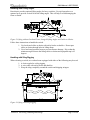
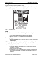
1
O & M Manual Type RTS03 Transfer Switches Russelectric Inc. South Shore Park, Hingham, Massachusetts 02043 Service 800 654-3020 www.russelectric.com 90E1720003 rev. D O&M Manual –90E1720003 Table of Contents List of Figures ............................................................................................................................................................. 5 Section 1 Hazard Categories and Special Symbols ................................................................................................. 6 Section 2 Introduction ............................................................................................................................................. 7 General Description ............................................................................................................................................... 7 Identification........................................................................................................................................................... 8 RTS03 Model Numbering System ........................................................................................................................... 8 Section 3 Safety Precautions ................................................................................................................................... 9 Section 4 Receiving, Handling and Storage .......................................................................................................... 10 Receiving .............................................................................................................................................................. 10 Handling ............................................................................................................................................................... 10 Handling with Eyebolts.................................................................................................................................... 10 Handling with Lifting Angles .......................................................................................................................... 11 Handling with Sling Rigging ........................................................................................................................... 11 Handling with a Forklift................................................................................................................................... 12 Storage.................................................................................................................................................................. 12 Section 5 Installation ............................................................................................................................................. 14 Installing the Transfer Switch............................................................................................................................... 14 Preparing the Site............................................................................................................................................. 14 Preparing the Foundation ................................................................................................................................. 14 Anchoring the Switch –Non Seismic ............................................................................................................... 14 Anchoring the Switch -Seismic........................................................................................................................ 15 Connect the Power Cables, Controls, and Wiring................................................................................................ 15 Connect the Power Cables ............................................................................................................................... 15 Torque Values for Mechanical Lugs................................................................................................................ 16 Conductor Restraint for Short Circuit Current Rating ..................................................................................... 18 Connect the Controls and Wiring..................................................................................................................... 21 Transfer Switch Inspection and Testing Before Operation................................................................................... 21 Check the Power Circuit Connections ............................................................................................................. 22 Check the External Equipment ........................................................................................................................ 22 Check the Auxiliary Equipment....................................................................................................................... 22 Check the Equipment Ground-Fault Systems .................................................................................................. 22 Conduct the Electrical Insulation Resistance Test ........................................................................................... 23 Section 6 Pre-Energizing Checkout Procedure...................................................................................................... 24 Section 7 Energizing the Transfer Switch ............................................................................................................. 26 Energize the Switch .............................................................................................................................................. 26 Section 8 Operation ............................................................................................................................................... 28 Transfer Switch..................................................................................................................................................... 28 Internal Manual Operation................................................................................................................................... 28 External Manual Operation (EMO) ..................................................................................................................... 30 RPTCS Control System......................................................................................................................................... 32 Overview.......................................................................................................................................................... 32 Graphical Control Panel Overview .................................................................................................................. 32 Summary of Function Key Operations ............................................................................................................ 33 Summary of LED Indicators ............................................................................................................................ 34 Summary of Control Pushbuttons .................................................................................................................... 34 Summary of the Graphical Display.................................................................................................................. 35 Performing Common Setup and Control Tasks .................................................................................................... 35 Setting Security Access.................................................................................................................................... 35 Setting the Date................................................................................................................................................ 36 Setting the Clock.............................................................................................................................................. 36 Setting Daylight Savings.................................................................................................................................. 36 Entering the Switch Designation...................................................................................................................... 36 Setting Timers.................................................................................................................................................. 37 Setting Voltage and Frequency Setpoints for S1 (VFS1) and S2 (VFS2)........................................................ 37 Setting Transition Mode on a Closed Transition Switch ................................................................................. 37 Setting Pre and Post for Elevator Contacts ...................................................................................................... 38 Setting up the Exerciser Function .................................................................................................................... 38 Performing a Load Test or a No Load Test .......................................................................................................... 39 Table of Contents Page 3 of 48 O&M Manual –90E1720003 Section 9 Maintaining the Transfer Switch ........................................................................................................... 40 Transfer Switch Inspection Guidelines ................................................................................................................. 40 Ideal Operating Conditions .............................................................................................................................. 40 Normal Operating Conditions.......................................................................................................................... 41 Harsh Operating Conditions............................................................................................................................. 41 General Inspection and Cleaning ......................................................................................................................... 42 Bus Bar Joints, Lug Terminations, and Insulating Materials............................................................................... 43 Section 10 Adverse Circumstances.......................................................................................................................... 44 Inspection Following a Short Circuit ................................................................................................................... 44 Clean-up Following a Short Circuit ..................................................................................................................... 44 Water-Soaked Switches......................................................................................................................................... 44 Section 11 Insulation Resistance Chart ................................................................................................................... 45 Section 12 Maintenance Log ................................................................................................................................... 46 Table of Contents Page 4 of 48 O&M Manual –90E1720003 List of Figures Figure 1: Lifting with an Overhead Crane and Eyebolts ........................................................................................... 10 Figure 2: Lifting with an Overhead Crane, Integral Lifting Angles and Cables or Chains ....................................... 11 Figure 3: Lifting with Sling Rigging. ........................................................................................................................ 11 Figure 4: Forklift Safety Strap................................................................................................................................... 12 Figure 5: Anchoring the Switch. ............................................................................................................................... 15 Figure 6: Power Connections 100-800A. .................................................................................................................. 16 Figure 6: Power Connections 1000-3000A. .............................................................................................................. 17 Figure 7: Wrapping the Cables.................................................................................................................................. 18 Figure 8: Wrapping the Space between Cables ......................................................................................................... 18 Figure 9: Finish Wrapping the Space between Cables .............................................................................................. 19 Figure 10: Continue Wrapping the Cables ................................................................................................................ 19 Figure 11: Securing Cables to Supports (optional).................................................................................................... 19 Figure 12: Tying the Rope Ends Together ................................................................................................................ 20 Figure 13: Locate the TB3 Terminal Block............................................................................................................... 21 Figure 14: Transfer Switch and Accessory Panel...................................................................................................... 28 Figure 15: Transfer Switch Position Indicators ........................................................................................................ 29 Figure 16: Internal Manual Operators ...................................................................................................................... 30 Figure 17: External Manual Operator (EMO) Handle............................................................................................... 31 Figure 18: External Manual Operator (EMO) Operation .......................................................................................... 31 Figure 19: Graphical Control Panel Overview .......................................................................................................... 32 Figure 20: Summary of Function Key Operations .................................................................................................... 33 Figure 21: Summary of LED Indicators .................................................................................................................... 34 Figure 22: Summary of Control Pushbuttons ............................................................................................................ 34 Figure 23: Summary of the Graphical Display.......................................................................................................... 35 Table of Contents Page 5 of 48 O&M Manual –90E1720003 Section 1 Hazard Categories and Special Symbols Read these instructions carefully and look at the equipment to become familiar with the equipment before trying to install, operate, service or maintain it. The following special messages may appear throughout this bulletin or on the equipment to warn of potential hazards or to call attention to information that clarifies or simplifies a procedure. The addition of either symbol to a “Danger” or “Warning” safety label indicates that an electrical hazard exists which will result in personal injury if the instructions are not followed. This is the safety alert symbol. It is used to alert you to potential personal injury hazards. Obey all safety messages that follow this symbol to avoid possible injury or death. DANGER indicates an imminently hazardous situation which, if not avoided, will result in death or serious injury. WARNING indicates a potentially hazardous situation which, if not avoided, can result in death or serious injury. CAUTION indicates a potentially hazardous situation which, if not avoided, can result in minor or moderate injury. CAUTION used without the safety alert symbol, indicates a potentially hazardous situation which, if not avoided, can result in property damage. Please Note: Electrical equipment should be installed, operated, serviced, and maintained only by qualified personnel. No responsibility is assumed by Russelectric Inc. for any consequences arising out of the use of this material. Section 1 Hazard Categories and Special Symbols Page 6 of 48 O&M Manual –90E1720003 Section 2 Introduction This manual contains instructions for the proper installation, operation and maintenance of Russelectric transfer switches. The purchaser’s engineering, installation, and operating staff supervisors should familiarize themselves with this manual and become acquainted with the appearance and characteristics of each piece of equipment mounted or contained in the transfer switch. These instructions and procedures apply to Russelectric transfer switch installations. When special features or non-standard components are incorporated in the transfer switch, detailed instructions for these components are included in the equipment drawings specific to the project. General Description Russelectric transfer switches are manufactured from formed channel framework and code gauge sheet steel. All steel parts are prepared for painting by a five step cleaning, phosphatizing and sealing process. The parts are then painted utilizing a polyester powder coating applied by the electrostatic method and cured in a baking oven and is designed to stand up to normal industrial environments. Russelectric transfer switches are listed to UL1008, Underwriters Laboratories® (UL®). Russelectric transfer switches provide automatic or manual transfers between the utility and an alternate source. The operating temperature of this equipment is 10-40°C. Each transfer switch is custom designed to specifications. Structures and bus configurations are arranged according to customer specifications. Complete customer drawings are furnished for each transfer switch assembly and should be reviewed before installing the equipment. The drawings include elevation, one-line diagrams, control schematics and wiring diagrams. Extra features and special control options are often incorporated when specified by the purchaser’s order. The special features are shown on the drawings and diagrams for the specific transfer switch assembly. Instructions for the control panel can be found in the user’s manual. Section 2 Introduction Page 7 of 48 O&M Manual –90E1720003 Identification Each Russelectric transfer switch is identified by a unique combination of model and serial numbers. These numbers, along with the electrical rating data, are provided on a nameplate affixed to the transfer switch and control system. Write the necessary information in the spaces provided on the sample nameplate, to keep a permanent and readily available record. This data is required to specifically identify your unit when contacting Russelectric personnel. Controller Type Enclosure Rating Enclosure Type Terminal Type Voltage Poles Ampere Rating Operator Switch Type Operation Type RTS03 Model Numbering System A = Automatic M= Manual T = Transfer Switch A = Single Operator B = Dual Operator C = Closed Transition 100 = 100A 150 = 150A 225 = 225A 260 = 260A 400 = 400A 600 = 600A 800 = 800A 1000 = 1000A 1200 = 1200A 1600 = 1600A 2000 = 2000A 2500 = 2500A 3000 =3000A 4000 = 4000A Section 2 Introduction 2 = 2 Pole 3 = 3 Pole 4 = 4 Pole A = 277/480V B = 480V C = 120/208V D = 208V E = 120/240V F = 240V G = 347/600V H = 265/460V I = 460V K = 120V M = Mechanical Lug O = Other C = Compression Lug F = Freestanding OV = Open Style 1 = Type 1 2 = Type 2 3 = Type 3 3R = Type 3R 4 = Type 4 4X = Type 4X 12 = Type 12 1G = Type 1 Gasketed RPTCS01 = Level 1 Controller RPTCS02 = Level 2 Controller RPTCS03 = Level 3 Controller RPTCS04 = Level 4 Controller RPTCS05 = Level 5 Controller Page 8 of 48 O&M Manual –90E1720003 Section 3 Safety Precautions This section contains important safety precautions that must be followed before attempting to lift, move, install, use, or maintain Russelectric transfer switches and associated components. HAZARD OF ELECTRIC SHOCK, EXPLOSION, OR ARC FLASH Follow NFPA 70E safety procedures and safe work practices and wear appropriate personal protective equipment (PPE). This equipment must be installed and serviced only by qualified electrical personnel. Perform such work only after reading and understanding all of the instructions contained in this manual. Turn off all power supplying this equipment before working on or inside equipment. Always use a properly rated, voltage sensing, device to confirm power is off. Before performing visual inspections, tests, or maintenance on this equipment, disconnect all sources of electric power. Assume all circuits are live until they are completely de-energized, tested, and tagged. Pay particular attention to the design of the power system. Consider all sources of power, including the possibility of backfeeding. Always practice lock-out/tag-out procedures according to OSHA and NFPA70E requirements. Conduct electrical testing to confirm no short-circuits were created during installation, maintenance, or inspection. Be aware of potential hazards; wear personal protective equipment, and take adequate safety precautions. Carefully inspect your work area, and remove any tools and objects left inside the equipment. Replace all devices, doors, and covers before turning on power to this equipment. All instructions in this manual are written with the assumption that the customer has taken these measures before performing maintenance or testing. Failure to follow these instructions will result in death or serious injury. Section 3 Safety Precautions Page 9 of 48 O&M Manual –90E1720003 Section 4 Receiving, Handling and Storage Russelectric Transfer Switches are shipped assembled in one or several shipping sections, depending on the size of the lineup and the handling facilities at the installation site. Transfer switches are mounted on wooden skids or boxes and enclosed in a covering to protect them from atmospheric conditions. Receiving Upon receipt, check the packing list against the equipment received to ensure the order and shipment are complete. Also upon receipt, immediately inspect the transfer switch for any damage that may have occurred in transit. If damage is found or suspected, file a claim with the carrier immediately, and notify Russelectric Field Services at 1-800-654-3020. Handling Ensure that proper equipment, such as an overhead crane, is available at the installation site to handle the switch. This equipment will help avoid injury to personnel and damage to the switch. For ease of handling by a crane, all free standing switches are equipped with eye bolts or lifting angles at the top of each switch. The lifting angle (if provided) has multiple 2-inch diameter holes for acceptance of crane hooks as shown in Figure 2 on page 10. Use a suitable spreader beam to maintain the integrity of the lifting straps. Variations in the center of gravity may cause the equipment to tilt to one side or the other. Handling with Eyebolts Russelectric provides eyebolts as standard equipment for freestanding enclosures. Use rigid spreaders or a spanner bar to provide vertical lift on the eyebolts. This will help to avoid damaging the frame or finish. Figure 1: Lifting with an Overhead Crane and Eyebolts Section 4 Receiving, Handling and Storage Page 10 of 48 O&M Manual –90E1720003 Handling with Lifting Angles Russelectric provides optional lifting angles for heavy switches. Use rigid spreaders or a spanner bar to provide vertical lift on the lifting angles. This will help to avoid damaging the frame or finish. Figure 2: Lifting with an Overhead Crane, Integral Lifting Angles and Cables or Chains Follow these instructions to handle the switch: 1. Use load-rated cables or chains with safety hooks or shackles. Do not pass cables or chains through holes in lifting straps. 2. Use a load-rated spreader beam to prevent structure damage. Rig so that the minimum angle between the lifting cables or chains and equipment top is 45 degrees. Handling with Sling Rigging When elevating a switch, an overhead crane equipped with either of the following may be used: 1. A chain coupled to a sling rigging 2. A wire cable with safety hooks and shackles 3. Wrap the sling completely around the switch and shipping stringers Figure 3: Lifting with Sling Rigging. Section 4 Receiving, Handling and Storage Page 11 of 48 O&M Manual –90E1720003 Handling with a Forklift A forklift is an alternative method of handling the switch. NOTE: Always check the fork lengths to ensure that the forks extend under the entire transfer switch. Carefully balance the load and always use a safety strap when handling or moving the transfer switch with a forklift. Figure 4: Forklift Safety Strap Storage If the Russelectric transfer switch is to be stored before being placed into service, perform the steps listed below. 1. Unpack the equipment to check for completeness and condition. 2. Reseal the equipment in its packing for protection until installation. When storing the equipment: 1. Keep the equipment in a clean, dry place that is free from corrosive elements and mechanical abuse. NOTE: Indoor equipment should be stored in an atmospherically controlled building until installation. Keep the equipment clean and dry, with a humidity less than 80% and temperature between 32 °F (0 °C) and 104 °F (40 °C). Avoid moisture, changes in temperature, cement dust, and corrosive atmospheres. 2. Covering the equipment with a tarpaulin may be necessary to protect it from contaminants or moisture. 3. Do not store indoor units outdoors. 4. If it is necessary to store the equipment outdoors, make special arrangements to keep the equipment clean, dry, and within the temperature and humidity limits stated above. Section 4 Receiving, Handling and Storage Page 12 of 48 O&M Manual –90E1720003 It may be necessary to cover the equipment and install temporary heating units. Place the equipment on level surfaces for storage to maintain structural integrity. 5. In areas of high humidity, such as installations near oceans or rivers, monitor the transfer switch closely. If necessary, use additional heat to keep the equipment dry. Contact Russelectric Services at 1-800-654-3020 if the internal heaters are not adequate for your location. 6. If optional internal heaters are supplied with the transfer switch, connect them to an external power source. Energize the heaters inside the transfer switch, or add heat from a separate source, such as a light bulb or blower. Use a minimum of 250 watts of heat per switch to keep the equipment dry during storage. Section 4 Receiving, Handling and Storage Page 13 of 48 O&M Manual –90E1720003 Section 5 Installation Before installing Russelectric transfer switches, read and understand: 1. All precautions in this manual. 2. All manuals for associated components. 3. All drawings and diagrams included with the equipment. Installing the Transfer Switch When correctly installed the: 1. 2. 3. 4. Enclosure is straight, level and perpendicular to the mounting surface. The switch is fastened securely to the floor or wall. The shipping sections are bolted together securely if applicable. Cable and control wiring connections are connected properly. Preparing the Site Before positioning the equipment, check these items to ensure that the site is ready for final installation. 1. Compare the site plans and specifications with the equipment drawings to be sure no discrepancies exist. 2. Check the site to confirm switch will fit properly. 3. Provide area ventilation at all times to maintain the ambient temperature around the equipment between 50 °F (10 °C) and 104 °F (40 °C). 4. Provide adequate permanent lighting and convenience outlets near the equipment. 5. Route sewer, water, and steam lines away from the equipment. 6. Provide floor drains near the equipment. 7. When installing the equipment, consider the aisle space required at the front and rear of the equipment as well as either side. NOTE: Required minimum clearances around the transfer switch are given in Article 110.26 of the National Electrical Code® (NEC®). These clearances are only a minimum. Additional space may be required for maintenance or removal of components. Preparing the Foundation 1. Special consideration must be taken when preparing the foundation. Follow all applicable local and international building codes. 2. Confirm that the floor or foundation is strong enough to support the equipment without distortion or sagging. NOTE: Refer to the shipping documents for actual weights of the equipment. 3. Confirm that the concrete is level left-to-right and front-to-rear to within 1/8-inch per square yard. 4. Install equipment on a smooth, level base to keep tolerances and adjustments to a minimum. Anchoring the Switch –Non Seismic 1. Four 5/8-inch diameter holes are supplied to anchor the free standing enclosure. Use all four mounts to anchor the switch to the foundation properly. Section 5 Installation Page 14 of 48 O&M Manual –90E1720003 2. Anchor the switch to the floor (Figure 5) with four 1/2-inch Grade 2 minimum bolts, flat washers, and anchors (not furnished). Figure 5: Anchoring the Switch. Anchoring the Switch -Seismic During an earthquake, the switch can move in any direction. Any incoming cables must accommodate this motion. The switch enclosure should not be used to mount exterior equipment. Any mounted equipment will negate seismic certification. When anchoring for a seismic location: 1. When anchoring for a seismic location, consideration must be given to the design of the pad or foundation. Minimum concrete thickness and psi, minimum anchor edge distance, centerline spacing, and effective embedment are all factors that will influence the anchoring. 2. Refer to a seismic study done by a certified engineer for proper anchor detail information. 3. Use an anchor that meets or exceeds the strength of a 1/2-inch Grade 5 bolt with ½” USS large flat washer. Connect the Power Cables, Controls, and Wiring Connect the Power Cables LOSS OF EQUIPMENT GROUND-FAULT PROTECTION Do not connect grounding conductors to any load neutral terminal(s). Failure to follow this instruction can result in equipment damage. NOTE: When connecting power cables, use 90 °C insulated conductors based on the ampacity of 75 °C conductors unless otherwise indicated by supplemental instructions. Russelectric transfer switches are provided with compression or mechanical type lugs for terminating the main power cables. 1. Determine the Source or Load and phase of each cable before making the connection See Figure 6. Note: Viewing the switch from the front, the pole sequence is phased N-A-B-C left-to-right. Non-standard arrangements may be necessary to meet specific requirements. If so, the bus is marked A, B, C, and N in the order specified by the customer. If an optional solid neutral is provided, all the connections for the neutral are labeled. Section 5 Installation Page 15 of 48 O&M Manual –90E1720003 2. Avoid sharp turns, corners, and edges when forming cables for termination within the switch. This reduces the risk of damage to equipment or weakening of the cable insulation. The cable manufacturer’s instructions should be followed in determining the minimum bending radii of the cables. This will vary with the type and size of cable involved. Refer to the NEC requirements for more information regarding minimum bending radii of cables. 3. Securely lace and support the line and load cables as directed in “Conductor Restraint for Short-Circuit Current Rating“, on page 17. Note: This helps avoid strain or load on the terminals. Torque Values for Mechanical Lugs Socket Size Across Flats 1/4 in 5/16 in 3/8 in 1/2 in Torque Value 200 in-lbs 275 in-lbs 375 in-lbs 500 in-lbs Table 1: Torque Values for Mechanical Lugs Load Power Connections Source 1 Power Connections Source 2 Power Connections Figure 6: Power Connections 100-800A. Section 5 Installation Page 16 of 48 O&M Manual –90E1720003 Load Power Connections (Behind Control Panel) The Control Panel is hinged to get access to the Load and S1 Power Connections Source 1 Power Connections Source 2 Power Connections Figure 6: Power Connections 1000-3000A. Section 5 Installation Page 17 of 48 O&M Manual –90E1720003 Conductor Restraint for Short Circuit Current Rating HAZARD OF CONDUCTOR MOVEMENT UNDER SHORT CIRCUIT CONDITIONS Restrain conductors in the transfer switch based on Table 2. Failure to follow this instruction can result in equipment damage. Refer to Table 2 to determine if cable restraints are required. If restraints are required, perform the steps following the table. Supply Cables Up to 2000A 3200A 4000A 5000A 100 ka No No No No 200 ka Yes Yes Yes Yes Load Cables Up to 800A 1600A 2000A 3200A 4000A 5000A 100 ka No No No No No No 200 ka Yes Yes Yes Yes Yes Yes Table 2: Conductor Restrain Requirements Note: Wrap conductors using 1/2-inch (13 mm) diameter sisal rope or equivalent. Lugs 1. Begin wrapping the conductors (Figure 7) 6 inches from the end of the lugs Conductors a. Wrap the conductors four (4) times as shown, leaving 3 ft (1 m) of excess rope at the first end (A). b. Pull the rope (B) taut. Wrap 1/2 in (13mm) sisal rope or equivalent Figure 7: Wrapping the Cables 2. Wrap the rope several times (Figure 8) until the space between the conductors are completely filled. a. Weave the final rope loop underneath the previous loop. b. Bring the rope through the right-hand space. c. Pull the rope taut. Starting from inside, wrap cable outwards Figure 8: Wrapping the Space between Cables Section 5 Installation Page 18 of 48 O&M Manual –90E1720003 3. Wrap the rope several times until the spaces between the conductors (Figure 9) are completely filled. a. Weave the final rope loop underneath the previous rope loop. b. Pull the rope taut. 4. Bring the cables together and wrap the cables 6 inches from the first wrap. Continue wrapping the cables every 11 inches until the cables exit the switch (Figure 10). 5. If cable supports are provided (optional) wrap cable supports (Figure 11) Starting from inside, wrap cable outwards Loop end (A) under cables 6. Tie the rope ends together (Figure12) until they are taut. Cut off excess rope, and tape ends to prevent fraying. Figure 9: Finish Wrapping the Space between Cables 7. Recheck torques of wire binding screws after securing the conductors. Figure 10: Continue Wrapping the Cables Support channel shown Figure 11: Securing Cables to Supports (optional) Section 5 Installation Page 19 of 48 O&M Manual –90E1720003 end (A) end (B) Figure 12: Tying the Rope Ends Together Section 5 Installation Page 20 of 48 O&M Manual –90E1720003 Connect the Controls and Wiring 1. Locate the customer control terminal block TB3 (Figure 13) located behind the upper door. TB3 Terminal Block Figure 13: Locate the TB3 Terminal Block 2. Refer to the wiring diagrams supplied with the switch for proper field connections to the TB3 terminal block. Note: The TB3 terminal block has been tagged at the factory and is shown on the connection diagrams for each installation. 3. Check control wiring with the connection diagram to confirm all connections have been made properly and loose connections tightened properly. Note: If the control power source is other than an internal control power transformer, the wires from the source to the switch must be of adequate size to avoid excessive voltage drop during operation. Transfer Switch Inspection and Testing Before Operation After the Russelectric transfer switch and components have been installed and all control and primary connections made; perform a final inspection and test before placing the switch into service. When installed correctly, the transfer switch conforms to the following requirements: 1. Front panels and doors form a straight, true line; and when transformers and/or other gear are included, the front panel’s line up or form parallel lines. Section 5 Installation Page 21 of 48 O&M Manual –90E1720003 2. The switch is fastened securely to the floor channels or base pad. 3. Bus and control wiring connections are connected properly. Directions for testing relays, instruments, meters, circuit breakers, and other electronic devices that are included in the assembly are given in the instruction bulletin for each individual device. Settings for protective devices are determined from a coordination study performed by the purchaser, consultant, or provided by Russelectric. Factory settings are used for production testing and may not reflect specific site requirements. Selection of test equipment depends on the rating and type of installation. A multi-meter is necessary to check the continuity of control circuits. A megohm meter is also needed for testing. Check the Power Circuit Connections Perform the following steps to check power circuits. 1. Check wire connections and bolted bus connections to confirm that no loosening or damage occurred during shipment or installation. Immediately replace any covers or barriers that were removed to check connections. Note: Correct torque values are listed on labels located in the transfer switch enclosure and in table 1 of this manual. Check the External Equipment Perform continuity checks for the connections to external equipment, such as remote controls, interlock circuits, and auxiliary switches. Refer to the appropriate procedures in the instruction bulletin for each individual device being tested. Check the Auxiliary Equipment Relays included on or in the instrument panels are set for manufacturing testing levels when shipped. 1. Determine the final relay settings from a coordination study performed by the purchaser, consultant, or provided by Russelectric. 2. Make necessary modifications to the relay settings according to the instruction bulletin for that particular relay. 3. Circuit monitors and power meters included on the front of the equipment may or may not be properly configured. The final configuration of these devices must be set by the purchaser or consultant. Refer to the circuit monitor and power meter instruction bulletins when setting these devices. Check the Equipment Ground-Fault Systems Paragraph 230-95(c) of the National Electrical Code requires that all equipment ground-fault protection systems be tested when first installed. Record results on the ground fault system test log. Note: If a complete check of the ground-fault system is necessary, use primary injection testing. If the system is multiple source and/or requires field connections at the job site, use primary injection testing. Section 5 Installation Page 22 of 48 O&M Manual –90E1720003 Note: Some ground fault systems require field connections at the job site. Consult the switchgear interconnection wiring drawing for details. Conduct the Electrical Insulation Resistance Test Russelectric transfer switches are factory tested for dielectric insulation strength. Conduct dielectric testing once the switch is installed. This testing will help identify shortcircuits and undesirable grounds in the switch and help identify any potential damage to the insulation during transport and installation. 1. Refer to ANSI/IEEE C37.20.1 for information regarding field dielectric testing. 2. Disconnect the RPTCS controller plugs. If supplied, open all control power and metering disconnects, or remove the fuses from the control circuits. 3. (If supplied) Isolate all supply voltage to solid-state controls on closed transition switches. 4. Isolate any and all control power equipment for metering or annunciation accessories. 5. Consult factory concerning how to handle other, special wiring conditions 6. With the neutral isolated from the ground and the power switches and circuit breakers open, conduct electrical insulation tests from phase-to-phase, phase-toground, phase to-neutral, and neutral-to-ground. Note: If the resistance reads less than one megohm while testing with the branch circuit devices in the Open position, the system may be unsafe and should be investigated. Consult Russelectric Services at 1-800-654-3020 to help you correct any problems. 7. After completing the electrical insulation test, replace all control power fuses that may have been removed and close power disconnects that have been opened. Energize supplies as desired. Section 5 Installation Page 23 of 48 O&M Manual –90E1720003 Section 6 Pre-Energizing Checkout Procedure Conduct a complete inspection before the switch is energized to ensure that all components function and operate properly. Complete every step of the checkout procedure listed before energizing the transfer switch. 1. Check all field-installed bus bar connections. 2. Check all accessible connections for tightness. 3. Check all factory and field-installed lug terminations for tightness. 4. Check the rigidity of all bus bar supports. 5. Verify the phase rotation of both the S1 and S2 sources are the same. 6. Check the enclosure for dents or other damage that reduces electrical clearances inside the enclosure. 7. On closed transition switches. Verify that at least one of the source breakers is equipped with a shunt trip and is wired to either the source 1 or source 2 circuit breaker trip connections on the customer connection terminal strip. 8. Insure the transfer switch is in the utility source position (S1). On closed transition switches, insure that the switch contacts are not closed on both sources, by observing the position indicator on the contact shafts. 9. Remove all foam blocks, or other temporary cushioning or retaining material, from the electrical devices. 10. If provided, open and close all circuit breakers and other operating mechanisms, checking for correct alignment and free operation. 11. Check all relays, meters, and instrumentation to verify that all field installed wiring connections are made properly and that the devices function properly. Section 6 Pre-Energizing Checkout Procedure Page 24 of 48 O&M Manual –90E1720003 12. On switches containing an electronic trip circuit breaker, set the tripping characteristic curve of the adjustable electronic trip unit per the job requirements, or as outlined in the respective instruction manual. 13. Verify that all grounding connections are correctly made. If the transfer switch is used as a service entrance, double check to see that the main bonding jumper is connected. 14. Check all field-installed wiring. Make certain it is clear of all live parts, and when instructed, secured to withstand fault currents 15. Vacuum to remove any dust, scrap wire, or other debris. 16. Replace all covers; check for any pinched wires, and close doors. Make certain all enclosure parts are properly aligned and fastened securely. Section 6 Pre-Energizing Checkout Procedure Page 25 of 48 O&M Manual –90E1720003 Section 7 Energizing the Transfer Switch HAZARD OF ELECTRIC SHOCK, EXPLOSION, OR ARC FLASH Correct short circuit conditions detected during the checkout procedures described in “Section 6 – Pre-Energizing Checkout Procedure”. Qualified electrical personnel must be present when energizing this equipment for the first time. Follow the instructions in this section to properly energize this transfer switch. Failure to follow these instructions will result in death or serious injury. Warning –Only Trained Personnel should perform this procedure. Follow all NFPA 70E safety procedures and wear proper PPE. Note: It is standard practice when energizing a transfer switch for the first time to close one of the source feeder breakers and leave the other source breaker locked out and tagged out until all settings and timers are verified correct. Note: This procedure does not replace startup by a qualified Russelectric field service technician; such service should be scheduled by calling Russelectric services at 1-800-6543020. Energize the Switch 1. No load should be on the transfer switch when it is energized. Turn off all downstream loads. The transfer switch should be in the S1 position. 2. Energize the switch in the following sequence: a. Close any open doors and/or covers. b. Close the preferred source (S1) circuit breaker. c. Verify the RPTCS controller and OIP power up. d. Verify all settings and timers per the specification sheets provided with the switch. e. Verify the transfer switch is connected to or transferred to the energized (S1) source by checking the indicators on the OIP or the optional LED indicators on the accessory panel (See Section 8 Operation). f. Close the S2 circuit breaker. g. Perform a no-load test per Section 8 Operation of this manual. h. Verify the generator started by checking the S2 available LED is lit. i. Cancel the no-load test. After the engine cooldown timer (TDEC) times out the engine will shut down. j. Perform a load test. k. Verify that the transfer switch transfers to the S2 source by check the status on the RPTCS OIP. Section 7 Energizing the Transfer Switch Page 26 of 48 O&M Manual –90E1720003 l. Cancel the load test and verify that the engine shuts down. m. Close all downstream load circuit breakers. n. Perform a load test. o. Verify that the transfer switch transfers to the S2 source by checking the status on the RPTCS OIP. p. Cancel the load test and verify that the engine shuts down. Section 7 Energizing the Transfer Switch Page 27 of 48 O&M Manual –90E1720003 Section 8 Operation This section describes the proper operation of the transfer switch. Transfer Switch The transfer switch provides two sets of fully-rated contacts for transferring the load between source 1 and source 2. One or two unidirectional motors or solenoids are used to operate the contacts. There are also auxiliary contacts for the control system and customer use. A manual operator is provided on open transition switches to provide backup if the control system fails. The front of the switch includes an accessory panel that includes the RPTCS interface panel, status lights and optional accessories. Accessory Panel RPTCS Interface Panel Optional Transfer Switch Status Indicators Optional Accessories Figure 14: Transfer Switch and Accessory Panel Internal Manual Operation Open transition transfer switches can be manually operated by operating a crank handle on the end of the operator(s). HAZARD OF ELECTRIC SHOCK, EXPLOSION, OR ARC FLASH Only properly trained personnel should perform this procedure. It is preferable to perform this procedure when the switch is deenergized and locked and tagged out. If this procedure is to be performed on a live switch follow all NFPA 70E safety procedures and wear proper PPE. Failure to follow these instructions will result in death or serious injury. Warning –Lethal voltages exist inside the transfer switch enclosure. Only Trained Personnel should perform this procedure. Follow all NFPA 70E safety procedures and wear proper PPE. Section 8 Operation Page 28 of 48 O&M Manual –90E1720003 Follow these instructions to manually operate the transfer switch: 1. Open the enclosure door 2. Verify the current position of the transfer switch by observing the position indicator labels on the S1 and S2 cross arms (see figure 23). There is a mechanical interlock on the transfer switch that prevents the switch from being connected to both sources at the same time. On dual operator switches the closed source must be opened first, and then the open source can be closed. Position Indicator 100-800A Transfer Switches 1000-3000A Transfer Switches Figure 15: Transfer Switch Position Indicators 3. Locate the manual operators on the end of the electrical operators. Section 8 Operation Page 29 of 48 O&M Manual –90E1720003 100-800A Transfer Switches 1000-3000A Transfer Switches Figure 16: Internal Manual Operators 4. Crank the handle per the instructions on the label. External Manual Operation (EMO) Open transition transfer switches can be supplied with an optional external manual operator. HAZARD OF ELECTRIC SHOCK, EXPLOSION, OR ARC FLASH Only properly trained personnel should perform this procedure. Failure to follow these instructions will result in death or serious injury. Warning –Follow all NFPA 70E safety procedures and wear proper PPE. Follow these instructions to external manually operate the transfer switch: 1. Verify the current position of the transfer switch by observing the position LEDs on the on the RPTCS controller or the optional status indicator lights on the accessory panel. There is a mechanical interlock on the transfer switch that prevents the switch from being connected to both sources at the same time. On dual operator switches the closed source must be opened first, and then the open source can be closed. 2. Locate the external manual operator handle (EMO) that was supplied with the switch. A separate mounting kit was also supplied with the switch to mount the handle either on the enclosure or another location. Section 8 Operation Page 30 of 48 O&M Manual –90E1720003 Figure 17: External Manual Operator (EMO) Handle 3. Open the EMO covers located on the lower door. 4. Insert the EMO handle into the socket on the end of the operator and follow the instructions on the door. Figure 18: External Manual Operator (EMO) Operation Section 8 Operation Page 31 of 48 O&M Manual –90E1720003 RPTCS Control System Note: The following is a brief overview of the basic setup and control tasks of the RPTCS controller. There are many other control features, internal and external accessories that may be included. Please refer to Instruction Manual 90E1730001 and the specific project documents for more information on these features. Overview The RPTCS is a modular control and monitoring system designed specifically for low- and medium-voltage transfer switch applications. The RPTCS provides the following key benefits: 1. Modular design reduces the number of spare components for maintenance and testing. 2. Multiple communication protocols allow simple integration into monitoring and control systems. 3. Graphical control panel Interface provides local control and access to system information. 4. Integrated pushbuttons and LED Indicators reduce external components and wiring. 5. Automation FlexLogic™ with interlocking and programmable logic control. Graphical Control Panel Overview Graphical Control Panel overview The Graphical Display is a 320 by 240 The Graphical Display is a 320 by 240 pixel (3.5 inch) backlit color LCD pixel (3.5 inch) backlit color LCD screen that provides the operator with screen that provides the operator with rapid access to relevant information on rapid access to relevant information on the ATS status, controls and settings the ATS status, controls and settings using intuitive sequences. using intuitive sequences. Function Keys Function Keys to perform the to perform the labeled labeled functionality. functionality. Red & Green LED Indicators Red & Green LED Indicators to provide: to provide: •Alarm Indication •Alarm Indication •Time delay Indication •Time delay Indication •Transfer Inhibit Indication •Transfer Inhibit Indication •Source Available Indication •Source Available Indication •Source Connected Indication •Source Connected Indication Front Panel Control Front Panel Control Pushbuttons Pushbuttons for direct access to: for direct access to: •Alarm Resets •Alarm Resets •Various System Tests •Various System Tests •Control Mode Screens •Control Mode Screens •Information Screens •Information Screens Front Port Front Port Communication Access Communication Access USB 2.0 Type Mini-B for USB 2.0 Type Mini-B for serial communication with serial communication with Laptop to download, Laptop to download, upload of data or real time upload of data or real time control functions. control functions. Figure 19: Graphical Control Panel Overview Section 8 Operation Page 32 of 48 O&M Manual –90E1720003 Summary of Function Key Operations Summary of Function Key Operations DOWN key: DOWN key: Scroll down Scroll down page, select page, select field, tab to field, tab to previous field, previous field, decrement decrement value. value. UP key: UP key: Scroll up Scroll up page, select page, select field, tab to field, tab to next field, next field, increment increment value. value. HOME key: HOME key: Single press Single press recalls the home recalls the home page; double page; double press recalls the press recalls the default page. default page. ESCAPE key: ESCAPE key: Single press closes pop-up, Single press closes pop-up, cancels editing, deselects field, cancels editing, deselects field, moves to previous page; moves to previous page; sustained press logs out (cancels sustained press logs out (cancels security passcode entry). security passcode entry). ENTER key: ENTER key: Single press freezes Single press freezes scrolling and selects scrolling and selects field, edits selected field, field, edits selected field, saves edited value; saves edited value; double press sets the double press sets the selected field/page as selected field/page as default; sustained press default; sustained press logs in (enter security logs in (enter security passcode) passcode) HELP key: HELP key: Displays context Displays context sensitive help and sensitive help and Modbus address of Modbus address of selected function (if selected function (if applicable). applicable). Figure 20: Summary of Function Key Operations KEY HOME UP DOWN ESC ENTER HELP OPERATION Single press recalls the home page; double press recalls the default display Scroll up page, select field, tab to next field, increment value Scroll down page, select field, tab to previous field, decrement value Single press closes pop-up, cancels editing, deselects field, moves to previous page; sustained press logs out (cancels security passcode entry) Single press freezes scrolling and selects field, edits selected field, saves edited value; double press sets the selected field/page as default; sustained press logs in (enter security passcode) Displays context sensitive help and Modbus address Section 8 Operation Page 33 of 48 O&M Manual –90E1720003 Summary of LED Indicators Summary of the 7 LED Indicators S1 Status LED (Green): S1 Status LED (Green): Indicates that the load is Indicates that the load is connected to Source 1. connected to Source 1. S1 Available LED (Green): S1 Available LED (Green): Indicates that Source 1 is Indicates that Source 1 is present and within user present and within user defined limits. defined limits. ALARM LED (Red): ALARM LED (Red): Indicates that there is a Indicates that there is a problem with the ATS, or problem with the ATS, or that a user configurable that a user configurable alarm condition is active, alarm condition is active, or that the ATS is not in or that the ATS is not in AUTO mode. AUTO mode. TD ACTIVE LED (Red): TD ACTIVE LED (Red): Indicates that the controller Indicates that the controller is timing before taking the is timing before taking the next control action. next control action. XFER INHIBIT LED (Red): XFER INHIBIT LED (Red): Indicates that the controller Indicates that the controller will not automatically transfer will not automatically transfer to or from any source and that to or from any source and that operator intervention is operator intervention is required to transfer ATS. required to transfer ATS. S2 Available LED (Red): S2 Available LED (Red): Indicatesthat thatSource Source22isis Indicates present and within user present and within user defined limits. defined limits. S2 Status LED (Red): S2 Status LED (Red): Indicates that the load is Indicates that the load is connected to Source 2. connected to Source 2. Figure 21: Summary of LED Indicators Summary of Control Pushbuttons Summary of the Control Pushbuttons ALARM RESET: ALARM RESET: (For future use). (For future use). TEST: TEST: Takes the user directly to Takes the user directly to the System Test Screen. the System Test Screen. INFORMATION: INFORMATION: Takesthe theuser userdirectly directlytoto Takes the Event Report Screen. the Event Report Screen. CONTROL: CONTROL: Takes the user directly to Takes the user directly to the Control Screen that the Control Screen that allows the user to select allows the user to select certain modes of certain modes of operation. operation. Figure 22: Summary of Control Pushbuttons Section 8 Operation Page 34 of 48 O&M Manual –90E1720003 Summary of the Graphical Display Summary of the Graphical Display SELECTED PAGE: SELECTED PAGE: To improve readability, some To improve readability, some pages are labeled with pages are labeled with rectangular outlines or colored rectangular outlines or colored back grounds. Some pages back grounds. Some pages contain too many fields to display contain too many fields to display at once. These pages display at once. These pages display arrow bars at the right edge to arrow bars at the right edge to indicate that the page continues indicate that the page continues above or below the screen. above or below the screen. PATH INDICATION: PATH INDICATION: Pages are organized in a hierarchical Pages are organized in a hierarchical or tree-based menu structure. or tree-based menu structure. Pressing the ”ESC” key will bring Pressing the ”ESC” key will bring the page up one level. Pressing the the page up one level. Pressing the “Home” key will navigate straight to “Home” key will navigate straight to the home page as shown here. the home page as shown here. ACCESS LEVEL: ACCESS LEVEL: Indicates the present passcode level. When Indicates the present passcode level. When performing operations that require a higher level performing operations that require a higher level of security, a passcode entry dialog box opens. of security, a passcode entry dialog box opens. There are various operations cannot be performed There are various operations cannot be performed in lower access levels. A sustained press on the in lower access levels. A sustained press on the “ESC” key clears the security passcode. “ESC” key clears the security passcode. TIME & TIME & DATE DATE SOFT-KEY LABELS: SOFT-KEY LABELS: •Navigation (blue or gray •Navigation (blue or gray label); Used to traverse across label); Used to traverse across and down the hierarchy of and down the hierarchy of pages and the numeric setpoint pages and the numeric setpoint popupscreens. screens.AAblue bluelabel label popup will show the active page. will show the active page. • Functional (orange label); • Functional (orange label); Used to perform page-specific Used to perform page-specific functions. functions. •Status (red label); used as an •Status (red label); used as an indicator on some functions. indicator on some functions. SOFT-KEYS: SOFT-KEYS: Selects the Soft-Key Label Selects the Soft-Key Label directly above. The button directly above. The button is inactive if the Soft-Key is inactive if the Soft-Key Label is grayed out. Label is grayed out. Figure 23: Summary of the Graphical Display Performing Common Setup and Control Tasks This section is a guide to performing common setup and control tasks on the RPTCS controller. For further information about the RPTCS controller and please refer to the RPTCS control users manual. If external accessories have been provided please refer to the specification sheet provided in the shop drawing package for proper operation of these accessories. Setting Security Access There are three levels of access in the RPTCS. The default setting for “level 1” is “11111” and “level 2” is “22222” these passcodes can be reset. The “level 3” passcode is a Russelectric factory passcode that you cannot reset. 1 Go to setpoints\security. 2 Highlight access switch level and press <enter>. A passcode dialog box appears. 3 Enter the passcode that you want to change. Enter the level 1 passcode or level 2 passcode depending upon which passcode you want to change. 4 Scroll down to the passcode level # to be changed and press <enter>. 5 When the passcode dialog box pops up, set your new passcode using the <up and down arrow soft keys> and the <left and right arrow soft keys>. Press <enter> to set passcode. NOTE: Passcode reset to “level 0” after five minutes of passcode activation. Press sustained <escape> key to reset passcode to zero. Press sustained <enter> key and the passcode dialog box appears. Contact customer with encrypted code if you lose your passcode. You can find this code on the passcode dialog box. Section 8 Operation Page 35 of 48 O&M Manual –90E1720003 Setting the Date 1 Go to setpoints\config\system. 2 Scroll to set date and press <enter>. 3 A passcode dialog box appears; enter level #1 passcode. 4 Press <enter> again and a set date dialog box appears. 5 Use the <right and left arrow soft keys> and the <up and down arrow soft keys> to select the date. 6 Press <enter> to save the date settings. Setting the Clock 1 Go to setpoints\config\system. 2 Scroll to set clock and press <enter>. 3 A passcode dialog box appears; enter level #1 passcode. 4 Press <enter> again and a set clock dialog box appears. 5 Use the <right and left arrow soft keys> and the <up and down arrow soft keys> to select the military (24-hour) time. 6 Press <enter> to save time settings. Setting Daylight Savings 1 Go to setpoints\config\system. 2 Scroll to daylight savings and press <enter>. 3 A passcode dialog box appears; enter level #1 passcode. 4 Press <enter> again and a set daylight savings dialog box appears. 5 Use the <right and left arrow soft keys> and the up and down arrow soft keys> to select the military (24-hour) time. 6 Press <enter> to save daylight savings settings. Entering the Switch Designation 1 Go to setpoints\config; “ATS” should be highlighted 2 Press <enter> and a passcode dialog box will pop up on the screen. Enter this level 2 passcode and press <enter> again. 3 An ATS name dialog box pops up on the screen. <left and right arrow soft keys>, <up and down arrow soft keys> and a <shift soft key>appear on the screen. The <shift soft key> allows toggling between upper- and lower-case letters. 4 The screen will display a blinking first character. Press the <up and down arrow soft keys> to select the appropriate character that pertains to the name of the switch. 5 Press the <right arrow soft key> to move the curser to the next field. Use the <left arrow soft key> as needed to move back to the previous field. 6 Repeat steps #4 and #5 to enter the complete name of the transfer switch. 7 Press <enter> to save transfer switch name. NOTE There is a five-minute time limit for programming this data Section 8 Operation Page 36 of 48 O&M Manual –90E1720003 Setting Timers Note: All timers are set at the factory either as default factory settings or as a specified setting. Please refer to the specification sheet provided with the switch for these settings. 1 Go to Setpoints\operation\timers. “Delay for generator start” is automatically highlighted. 2 Press <enter>. 3 A passcode dialog box appears; enter level #1 passcode, and press <enter>. 4 Scroll down to the timer to be set, and Press <enter>. 5 Use the <up and down arrow function (hard) keys> to increase or decrease the timer setpoint by its incremental value noted in the Setpoints section. or Using the dialog box for setting the timers, press the <left and right arrow soft keys> and the <up and down arrow soft keys> to navigate the numeric keypad on the screen and then the <select soft key> to enter each digit of the timer setting directly, within the maximum, minimum and incremental limits for that timer, as noted in the Setpoints section. Press <enter> to save the timer settings. NOTE Timer designation cross reference: “Delay for generator start” is the same as “TDES” “Delay – xfer to nonpreferred source” is the same as “TDNPS” “Delay – xfer to preferred source” is the same as “TDPS” “Delay - cntr off position to nonpreferred source” is the same as “TDNNP” “Delay - cntr off position to preferred source” is the same as “TDNP” “Delay for engine cool down” is the same as “TDEC” Setting Voltage and Frequency Setpoints for S1 (VFS1) and S2 (VFS2) Note: All setpoints for are set at the factory either as default factory settings or as a specified setting. Please refer to the specification sheet provided with the switch for these settings. 1 Go to setpoints\operations. 2 Press the “S1” or the “S2” soft key. 3 Scroll down to parameter you want to set using the <up and down arrow function (hard) keys> and press <enter>. 4 A passcode entry dialog box appears; enter level 1 passcode and press <enter>. 5 Highlight parameter you want to set and press <enter>. 6 Use the <up and down arrow function (hard) keys> to set the desired parameter and press <enter> NOTE All Voltage parameters are set by percentage values Setting Transition Mode on a Closed Transition Switch 1 Go to setpoints\control\general. 2 Scroll down to “transition mode select” and press <enter>. 3 A passcode dialog box appears; enter level #2 passcode. 4 Press <enter> again and a transition mode select dialog box appears. 5 Use the <up and down arrow function (hard) keys> to scroll to the desired transition mode; press <enter>. 6 Press the <HOME> function key and confirm on the operator panel that the desired transition mode was selected. Section 8 Operation Page 37 of 48 O&M Manual –90E1720003 Setting Pre and Post for Elevator Contacts 1 Go to setpoints\operations\timer. 2 Use the <down arrow function (hard) key> scroll down to “Pre-load Control Timer” and press <enter> 3 A passcode dialog box appears; enter level #1 passcode. 4 Press <enter> again and a dialog box appears which allows you to set the timer. Use the <up and down arrow function (hard) keys> to incrementally increase or decrease the timer and press <enter> when the desired time is set. 5 Use the <up and down arrow function (hard) keys> to scroll to the “Post-load Control Timer”; press <enter>. 6 Set the “Post Load Control Timer” in the same manner as the “Pre-Load Timer”, noted in (4) above. Setting up the Exerciser Function 1 Press <exerciser soft key> on the Home page. 2 Press <set up soft key> on the exerciser screen to set up exerciser parameters 3 This screen defaults to highlight “Exerciser Type”; press <enter>. 4 A passcode entry dialog box appears; enter level 1 passcode and press <enter> 5 Use the <up and down arrow function (hard) keys> to choose the desired exerciser type (also called “CDT Events”); press <enter>. There are six options in this menu: “Yearly”, “Monthly”, “Biweekly”, “Weekly”, “Daily” and “Off”, as detailed below. 6 Use the <up and down arrow function (hard) keys> to scroll down to “CDT Event 1 start time”; press <enter>. 7 Set start time in 24-hr format, separately for second, minute and hour starting time values: When the screen first comes up, it defaults to seconds; Use the <up and down arrow function (hard) keys> to increment or decrement the starting seconds value; use the <left arrow soft key> to move from setting seconds to setting minutes value. As with the seconds, use the Use the <up and down arrow function (hard) keys> to set the minutes for starting time. Repeat the above to set the hour value for starting time. Press <enter> to save time setting. 8 Set exercise duration by scrolling down to “CDT Event 1 Duration” using the <up and down arrow function (hard) keys>. Press <enter> to open up “CDT Event 1 Duration” window and set duration time, using the <up and down arrow function (hard) keys> and the <left and right arrow soft keys>, similarly to start time setting above. Then press <enter> again to set duration time. 9 Set mode of exerciser (“Gen Start and Xfer” or “Gen Start Only” by scrolling down to “CDT Event Load” using <up and down arrow function (hard) keys>. Press <enter> and highlight what type of exerciser you want. Press <enter> again to set this exerciser mode. EXERCISER TYPES Yearly There can be up to 24 programmable events with 365 days. Set the date and start time, duration of the test and type of test. Monthly There can be up to 7 programmable events with 28 days. Set the date and start time, duration of the test and type of test. Biweekly There can be up to 7 programmable events with 14 days. Set the date and start time, duration of the test and type of test. Weekly There can be up to 7 programmable events with 7 days. Set the date and start time, duration of the test and type of test. Daily There can be up to 7 programmable events. Set the start time, duration of the test and type of test. Off The exerciser is disabled Section 8 Operation Page 38 of 48 O&M Manual –90E1720003 Performing a Load Test or a No Load Test 1 Press the green test button on the face of the controller; this will bring up the exerciser\test screen. 2 Press the grayed-out (disabled/inactive) <Xfer Load soft key> and a passcode dialog box pops up. 3 Enter the level 1 passcode and press <enter> 4 The <Xfer Load soft key> is now enabled, and has turned orange. Press the orange <Xfer Load soft key> to initiate load test. 5 The transfer switch times out and then transfers to Source 2. 6 To end the load test, press the <end soft key> and the transfer switch times out and retransfers to Source 1. NOTE A NO-Load test is performed in a similar manner, by pressing the <noXfer soft key> on the exerciser\test screen. Section 8 Operation Page 39 of 48 O&M Manual –90E1720003 Section 9 Maintaining the Transfer Switch HAZARD OF ELECTRIC SHOCK, EXPLOSION, OR ARC FLASH Inspect and perform preventative maintenance only on switches and equipment to which power has been turned to the OFF position, disconnected, and electrically isolated (unless otherwise specified) so that no accidental contact can be made with energized parts. Follow safety related work practices as described in NFPA 70 – Standard for Electrical Safety Requirements for Employee Workplaces and ASHA Standards -29 CFR Part 1910 Subpart S – Electrical. Failure to follow these instructions will result in death or serious injury. Periodic maintenance on the transfer switch includes cleaning, lubrication, and exercising component parts. The interval between maintenance checks can vary depending upon the amount of usage and environmental conditions of each installation. The maximum recommended inspection interval is one year. This definition for periodic maintenance applies throughout this manual, unless otherwise noted. Always inspect the switch after a fault. Transfer Switch Inspection Guidelines In general, the following guidelines may be followed. However, as conditions vary, the maintenance program must also be adapted to provide a long life for the equipment and the electrical system. Periodic inspection of the equipment will be necessary to establish the conditions to which the transfer switch is subjected (see “Ideal Operating Conditions” below, and “Normal Operating Conditions” and “Harsh Operating Conditions”). Perform inspections and maintenance according to these conditions. Inspect the equipment immediately after abnormal or stressful operating conditions occur or after the equipment experiences a fault current. These inspection and maintenance guidelines cover only Russelectric transfer switches. If conditions cannot be established and documented, then the harsh operating condition must be assumed. These inspection and maintenance guidelines do not warrant any field connections, field modifications, or supersede any maintenance procedures or schedules recommended by component manufacturers. For more information regarding the warranty of this product, refer to “Russelectric Conditions of Sale.” Ideal Operating Conditions When the equipment is operating under the “ideal operating conditions” outlined below, it should be able to operate without maintenance for a period of five years. Environmental Ambient room temperature range is 50 °F (10 °C) to 104 °F (40 °C). Altitude is less than 6600 ft (2012 m). Equipment is located indoors in a climate controlled room (heat/AC). Section 9 Maintaining the Transfer Switch Page 40 of 48 O&M Manual –90E1720003 Absence of dust or debris either airborne or settled. Relative humidity averaging less than 70%. Absence of vibrations or seismic activity. Circuit Loading Continuous loading (with 100% rated devices) is between 20- 80% of the equipment ratings. Average loading not exceeding 70% of the equipment rating. Only resistive or continuous motor loads, no welding or jogging loads. Transfer switching less than 52 cycles annually. Maximum of two circuit breaker trips due to overload or fault annually. Equipment Installation Torque all bus bar joints, lugs, and bolts to their appropriate tightness at installation. Securely tighten all control and communications wiring at installation. Follow pre-energizing checkout rigorously. Normal Operating Conditions When the equipment is operating under the “normal operating conditions” outlined below, it should be inspected and maintained every 1–3 years, or more frequently, based on the user’s experience. Environmental Ambient room temperature is between -22 °F (-30 °C) and 104 °F (40 °C). Altitude is less than 6600 ft (2012 m). The effect of solar radiation is not significant. Note: Refer to the principles outlined in IEEE Standard C37.24-1986 for additional information. Circuit Loading Transfer switching is no more than 104 cycles annually. Welding or jogging loads represents less than 15% of a circuit and/or equipment loading. Equipment Installation Torque all bus bar joints, lugs, and bolts to their appropriate tightness at installation. Securely tighten all control and communications wiring at installation. Follow pre-energizing checkout rigorously. Harsh Operating Conditions When the equipment is operating under the “harsh operating conditions” outlined below, it should be inspected and maintained every 6 months, or more frequently, based on the user’s experience. Environmental Ambient room temperature is less than -22 °F (-30 °C) or greater than 104 °F (40 °C). Altitude exceeds 6600 ft (2012 m). Section 9 Maintaining the Transfer Switch Page 41 of 48 O&M Manual –90E1720003 The effect of solar radiation is significant. The equipment is exposed to hot and/or humid climate. The equipment is exposed to damaging fumes, vapors, steam, salt air, and/or oil vapors. The equipment is exposed to seismic shock or abnormal vibrations or tilting. Circuit Loading The transfer switch operates frequently due to overloading or fault. Transfer switching exceeds 208 times annually. Welding loads or jogging loads represent greater than 15% of a circuit’s load. Equipment Installation Torque all bus bar joints, lugs, and bolts to their appropriate tightness at installation. Securely tighten all control and communications wiring at installation. Follow pre-energizing checkout rigorously. General Inspection and Cleaning HAZARD OF EQUIPMENT DAMAGE Do not use an air hose to blow out the switch. The dust may settle inside relays and over current devices, causing overheating and improper operation. Do not allow paint, chemicals, or petroleum based solvents to contact plastics or insulating materials Failure to follow this instruction can result in equipment damage. 1. Vacuum the switch interior to remove any dirt or dust deposits. Wipe all bus bars, insulators, cables, and so forth, with a clean, dry, lint-free cloth. 2. Check the switch interior carefully for moisture, condensation build-up, or signs of any previous wetness. Moisture can cause insulation breakdown and rapid oxidation of current carrying parts. Inspect all conduit entrances and cracks between the enclosure panels for dripping leaks. Condensation in conduits may be a source of moisture and must not be allowed to drip onto live parts or insulating material. Take the necessary steps to eliminate the moisture and seal off all leaks. 3. Inspect the switch for any signs of overheating. Discoloration and flaking of insulation or metal parts are indications of overheating. Note: If overheating occurs, be sure that all conditions that caused the overheating have been corrected. Loose or contaminated connections can cause overheating. 4. Check for signs of rodent nesting in the enclosure. If required, use a good exterminating technique in the general area of the equipment. Note: Do not place or use exterminating substances and chemicals inside the switch. Some of these products attract rodents. 5. Carefully inspect all devices for any visibly worn-out, cracked, or missing parts. 6. Open and close contacts several times to verify they are working properly. 7. Verify that all key interlocks and door interlocking provisions are working properly. Section 9 Maintaining the Transfer Switch Page 42 of 48 O&M Manual –90E1720003 Bus Bar Joints, Lug Terminations, and Insulating Materials HAZARD OF EQUIPMENT DAMAGE Do not stand or remove plating on any bus, splice plate, or terminal lug. Damage to plating can result in overheating. Replace damaged part. Contact Russelectric Inc. Field Services at 1-800-654-3020. Failure to follow this instruction can result in equipment damage. 1. Bus bar joints are maintenance-free. Do not retighten them after the pre-energizing checkout procedure is complete. 2. Check all bus bar joints and terminal lugs for any pitting, corrosion, or discoloration resulting from high temperatures or subjection to high fault conditions. If any damage has occurred, replace the bus bars or lugs. If cleaning is required, use LectraClean®, made by CRC. 3. Inspect all insulating materials. Before re-energizing the switch, replace insulators having any visible damage (such as cracks). Section 9 Maintaining the Transfer Switch Page 43 of 48 O&M Manual –90E1720003 Section 10 Adverse Circumstances This section includes, but is not limited to, all electrical components of the switch. HAZARD OF ELECTRIC SHOCK, EXPLOSION, OR ARC FLASH Turn off all power supplying the switch before cleaning Always use a properly rated voltage sensing device to confirm power is off. Failure to follow these instructions will result in death or serious injury. Note: Before attempting to re-energize the switch following adverse circumstances, contact Russelectric Services at 1-800-654-3020 for special instructions. Inspection Following a Short Circuit If a short circuit occurs, make a thorough inspection of the entire system, and verify that no damage to conductors or insulation has occurred. High mechanical and thermal stresses developed by short-circuit currents may damage conductors and insulation. Check the overcurrent protection device that interrupted the short-circuit current for possible arcing damage. Do not open sealed devices, such as molded case circuit breakers. These devices should be replaced if damaged before re-energizing the switch. Clean-up Following a Short Circuit The insulating properties of some organic insulating materials may deteriorate during an electrical arc. If so: 1. Remove any soot or debris. 2. Replace carbon-tracked insulation. Water-Soaked Switches Do not clean or repair a transfer switch that has been exposed to large volumes of water or submerged at any time. Current-carrying parts, insulation systems, and electrical components may be damaged beyond repair. Do not energize the equipment. Contact Russelectric Field Services at 1-800-654-3020. Section 10 Adverse Circumstances Page 44 of 48 O&M Manual –90E1720003 Section 11 Insulation Resistance Chart Always use a 500 or 1000 VDC megohm meter when testing insulation resistance. Note: The Neutral–Ground column is provided to record the results of the pre-energizing checkout procedure only. HAZARD OF ELECTRIC SHOCK, EXPLOSION, OR ARC FLASH Turn off all power supplying the switch before testing Always use a properly rated voltage sensing device to confirm power is off. Failure to follow these instructions will result in death or serious injury. Phase-Phase Date Neutral-Ground All Disconnects Open A-B Date Phase-Ground B-C C-A A-Ground B-Ground C-Ground Neutral-Ground C-A A-Ground B-Ground C-Ground Neutral-Ground All Disconnects Closed A-B B-C Section 11 Insulation Resistance Chart Page 45 of 48 O&M Manual –90E1720003 Section 12 Maintenance Log Date Section 12 Maintenance Log Description Page 46 of 48 O&M Manual –90E1720003