1
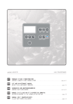
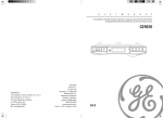
u
s
e
r
m
a
n
u
a
l
manual de usuario
7-5400
EXPORTER
Thomson Inc.
P.O. Box 1976
Indianapolis, IN 46206-1976
©2006 Thomson Inc.
Trademark(s) ® Registered
Marque(s) Deposée(s)
Marca(s) ® Registrada(s)
5639 2420 (EN/E)
www.ge-electronics.com
Printed In China
EN/E
• It is important to read this instruction book prior to
using your new product for the first time.
• Es importante leer este manual antes de usar por vez
primera su euipo.
FCC Information
EN
This device complies with Part 15 of the FCC
Rules. Operation is subject to the following two
conditions: (1) This device may not cause harmful
interference, and (2) this device must accept any
interference received, including interference that
may cause undesired operation. In accordance
with FCC requirements, changes or modifications
not expressly approved by Thomson Inc. could
void the user’s authority to operate this product.
This equipment has been tested and found to
comply with the limits for a Class B digital device,
pursuant to Part 15 of FCC Rules. These limits are
designed to provide reasonable protection against
harmful interference in a residential installation.
This equipment generates, uses, and can radiate
radio frequency energy and, if not installed and
used in accordance with the instructions, may
cause harmful interference to radio
communications. However, there is no guarantee
that interference will not occur in a particular
installation. If this equipment does cause harmful
interference to radio or television reception,
which can be determined by turning the
equipment off and on, the user is encouraged to
try to correct the interference by one or more of
the following measures
• Reorient or relocate the receiving antenna.
• Increase the separation between the equipment
and receiver.
• Connect the equipment into an outlet on a
circuit different from that to which the receiver is
connected.
GE
7-5400
Equipment tested for
compliance as a
complete unit
This product complies with DHHS Rules 21 CFR
Subchapter J. Applicable at the date of
manufacture.
For Your Records
Product: Spacemaker
Brand: GE
Model: 7-5400
In the event that service should be required, you
may need the model number. In the space below,
record the date and place of purchase:
Model No.
Date of Purchase
Place of Purchase
Electrical Consumption
Power Supply: 120V ~ 60Hz
Power Consumption: 72 Watts
Service Information
For Your Safety
The AC power plug is polarized
(one blade is wider than the
other) and only fits into AC
power outlets one way. If the
plug won’t go into the outlet
completely, turn the plug over and try to insert it
the other way. If it still won’t fit, contact a
qualified electrician to change the outlet, or use a
different one. Do not attempt to bypass this
safety feature.
CAUTION: TO PREVENT ELECTRIC SHOCK,
MATCH WIDE BLADE OF PLUG TO WIDE SLOT,
FULLY INSERT.
Main plug is used as the disconnect device, it
shall remain readily operable and should not be
obstructed during intended used. To be
completely disconnected the apparatus from
supply mains, the main plug of the apparatus
shall be disconnected from the mains socket
outlet completely.
• Consult the dealer or an experienced radio/TV
technician for help.
Also, the Federal Communications Commission has
prepared a helpful booklet, “How To Identify and
Resolve Radio TV Interference Problems.” This
booklet is available from the U.S. Government
Printing Office, Washington, DC 20402. Please
specify stock number 004-000-00345-4 when
ordering copies.
Technical Information
CAUTION
RISK OF ELECTRIC SHOCK
DO NOT OPEN
THE LIGHTNING
FLASH AND ARROWHEAD WITHIN THE
TRIANGLE IS A
WA R N I N G S I G N
ALERTING YOU OF
"DANGEROUS
VOLTAGE" INSIDE
THE PRODUCT.
CAUTION: TO REDUCE THE
RISK OF ELECTRIC SHOCK,
DO NOT REMOVE COVER
(OR BACK). NO USERS E RV I C E A B L E PA R T S I N S I D E . R E F E R S E RV I C I N G
TO QUALIFIED SERVICE
PERSONNEL.
THE EXCLAMATION
POINT WITHIN THE
TRIANGLE IS A
WARNING
SIGN
ALERTING YOU OF
I M P O R TA N T
INSTRUCTIONS
A C C O M PA N Y I N G
T H E P R O D U C T.
SEE
MARKING
ON BOTTOM
OF PRODUCT
SEE
MARKING
ON TOP/ BACK
OF PRODUCT
WARNING: TO PREVENT FIRE OR ELECTRICAL
SHOCK HAZARD, DO NOT EXPOSE THIS PRODUCT
TO RAIN OR MOISTURE.
IMPORTER
Comercializadora Thomson de México, S.A. de C.V.
Álvaro Obregón No. 151. Piso 13.
Col. Roma. Delegación Cuauhtémoc
C.P. 06700. México, D.F.
Telefono: 52-55-11-020360
RFC: CTM-980723-KS5
This product should be serviced only by those
specially trained in appropriate servicing techniques. For instructions on how to obtain service,
refer to the warranty included in this Guide.
AUDIO AND COMMUNICATIONS DIVISION PLEASE READ AND SAVE THIS FOR FUTURE REFERENCE
IMPORTANT
SAFETY INSTRUCTIONS
Some of the following information may not apply to your
particular product; however, as with any electronic product,
precautions should be observed during handling and use.
• Before using the product, please follow and adhere to all
warnings, safety and operating instructions located on the
product and in the user book. Save all instructions for
future reference.
• Do not expose product to rain and do not use near water;
such as, sink, wet basement, swimming pools, etc.
• Always leave sufficient space around the product for
ventilation. Do not place product in or on a bed, rug,
bookcase or cabinet that may prevent air flow through
vent openings.
• Do not expose product to extreme temperatures such as
found near a hot radiator or stove, or in a car parked in
the Summer sun.
• Connect power cord only to AC power source as marked on
the product.
• Some products employ a polarized AC line plug (one blade
is wider). This is a safety feature. The plug will go in the
power outlet only one way. If the plug doesn’t go into the
outlet completely, turn the plug over and put it in the
other way. If it still doesn’t fit, contact a qualified
electrician to change the outlet. Do not defeat the safety
purpose of the polarized plug.
• Route power cord to prevent it from being pinched, or
walked on, or melted by a hot stove or radiator.
• To clean cabinet, unplug AC power cord, then use a soft
cloth dampened only with water.
• Do not place lighted candles, cigarettes, cigars, etc. on the
product.
• Unplug AC power cord from outlet during a lightning
storm or when product is left unused for a long period of
time to prevent damage due to lightning or power line
surges.
• Care should be taken so that objects do not fall and liquids
do not spill into the product.
• Never add accessories that the product has not been
designed to accommodate.
• Use only the manufacturer’s approved mounting
instructions and hardware when installing product.
• Do not attempt to disassemble the cabinet. This product
does not contain customer serviceable components.
• Do not handle the unit or power cord when your hands
are wet or damp
• Damage Requiring Service–This product should be serviced
by qualified service personnel when:
A. The power supply cord or the plug has been damaged;
or
B. Objects have fallen, or liquid has been spilled into the
product; or
C. The product has been exposed to rain; or
D. The product does not appear to operate normally or
exhibits a marked change in performance; or
E. The product has been dropped, or the cabinet damaged.
• When service or repairs are completed, ask the service
technician to perform the safety check described in the
service manual and to confirm that replacement parts have
the same safety characteristics as the original parts.
• IF YOUR PRODUCT OPERATES ON BATTERIES, adhere to
the following precautions:
A. Any battery may leak electrolyte if mixed with a
different battery type, if inserted incorrectly, or if all
batteries are not replaced at the same time.
B. Any battery may leak electrolyte or explode if disposed
of in fire or an attempt is made to charge a battery not
intended to be recharged.
C. Discard leaky batteries immediately. Leaking batteries
can cause skin burns or other personal injury.When
discarding batteries, be sure to dispose of them in the
proper manner, according to provincial and local
regulations.
EN
First Things First
Table of Contents
Tools Required ................................... 2
Parts Packed with Your Unit ............ 2
Before Mounting ............................... 2
Mounting Procedure ......................... 3
Selecting Radio/TV Band ................. 11
Tuning to a Channel ....................... 11
Automatic Channel Search ............. 12
Radio Frequency Memory ............... 12
Memory Recall ................................. 12
RBDS (Radio Broadcast Data
System) ............................................. 12
Program Type Search ....................... 12
TV Band ............................................ 13
Weather Band .................................. 13
Getting Started .................................. 6
CD Player .......................................... 14
Automatic Time Set ........................... 6
Selecting Time Zone .......................... 6
Daylight Saving Time (DST) .............. 6
U.S. Time Zone (Figure 1) ................. 7
Canadian Time Zone (Figure 2) ........ 7
Selecting CD Player ......................... 14
Loading CD Disc ............................... 14
Play and Pause Playback ................. 14
Skip and Search Tracks .................... 14
End Playback .................................... 14
Repeat and Random Playback ........ 14
FCC Information
Table of Contents .............................. 1
EN
First Things First ................................ 2
Battery Backup Operation ................ 8
Installing Backup Battery .................. 8
Listening to External mp3 Player .......
.......................................................... 14
Under Cabinet Mounting
Instructions
Tools Required
•
•
•
•
•
•
•
•
Drill and 1/4" Drill Bit
Ruler or Tape Measure
Nail or Awl
Scissors
Screwdriver - Phillips
Countersink (Optional)
Masking Tape
Safety Glasses
Weather Forecast ............................ 15
Display .............................................. 10
Using the Countertop Light ........... 17
Thermometer ................................... 15
Empty contents of the selected cabinet under
which the unit will be mounted and thoroughly
clean the underside of the cabinet to remove any
grease residue which might be present.
EN
We recommend the unit be mounted at the front
edge of the cabinet.
Parts Packed with your Unit
Spacers
3 — 1/4"
3 — 1/2"
3 — 1"
3 — Washers
Important: For secure mounting, the screws
must go into the radio to a depth of at least 3/8".
If the overall length from the bottom of the
cabinet shelf to the bottom of the overhang is
more than 1 3/4", then a wood shim will be
necessary. A shim can be made from a sheet of
plywood, using the Template to locate the central
lines for drilling the 1/4" mounting holes. The
shim can be located between the cabinet shelf
bottom and spacers. Make sure the wood is at
least as thick as the excess over 1 3/4" If a shim is
necessary, longer screws are required. Longer
screws (Type #10-32) are available at most local
hardware stores.
Cut out the Template on the line indicated. The
Template size and screw hole positions are
identical to the top of the clock radio.
General Controls ................................ 9
Main Unit ........................................... 9
Side Views .......................................... 9
In Battery Compartment ................... 9
The Remote Control ........................ 10
Before Mounting
USE:
3 — 2 3/4" Phillips head screws
or
3 — 1 5/8" Phillips head screws
Replacing the Bulb .......................... 17
Clock & Timer .................................. 11
Setting the Time .............................. 11
Setting the Countdown Timer ....... 11
Troubleshooting Tips ....................... 17
2 — Cord hooks
Care and Maintenance ................... 18
Radio ................................................ 11
Built-In AFC ...................................... 11
Antennas .......................................... 11
Turning On the Radio ..................... 11
Turning Off the Radio ..................... 11
Limited Warranty ............................ 19
1 — Mounting
template
If no overhang, front edge of templet
should be even with front edge of cabinet.
Le bord avant du gabarit doit etre
de niveau avec le bord avant de l'amoire
FRONT
Fold guidelines for cabinet with overhang.
1
AVANT
Pliere le long des lignes pour les armoirs a rebord en saillie
2
First Things First
Mounting Procedure
1. If your cabinet does not have an
overhang:
(a) Position Template in desired location on
underside of cabinet, flush with front
edge.
(b) Then tape Template in place, and go to
Step 2.
EN
Note:
If your cabinet has glue blocks or
other obstructions, cut out corresponding
areas on the Template to clear them. Do not
cut out or cut through the screw holes
indicated on the Template.
Note:
It is recommended that safety
glasses be worn while drilling screw holes to
prevent the possibility of eye injury.
MOUNTING
TEMPLATE
If your cabinet has an overhang:
(a) Measure the thickness of the overhang.
(b) Fold front of Template downward along
the printed guideline that is closest to
the thickness of your cabinet.
(c) Tape fold-down portion to backside of
overhang, Tape Template to cabinet
underside.
3
2. Drill 1/4 -inch diameter holes through the
underside of the cabinet bottom shelf using
the 3 points marked on the Template.
FOLD TEMPLATE ON
DOTTED LINE
EN
Be sure to hold the drill very firmly against
the cabinet to reduce “walking” of the drill
bit from the markings.
Use masking tape above the hole locations
on inside of wooden cabinet shelf to help
reduce splintering.
MEASURE THICKNESS OF
CABINET OVERHANG
FRONT EDGE
OF CABINET
Tips:
On wooden cabinets you may want to mark
and start the drill holes with a nail or an
awl.
If installing the unit under a wood cabinet,
you may wish to countersink the drilled hole
from the INSIDE of the cabinet if a
countersink attachment for your drill is
available. This will eliminate the use of
washers and allow the screw heads to be
flush with the floor of your cabinet. If you
cannot countersink the holes, use the
supplied washers.
3. Remove Template and clean drill shavings
from inside and underside of cabinet.
4. If your cabinet does not have an
overhang, go to Step 5.
If your cabinet has an overhang, select
the spacer or combination of spacers that is
equal to or longer than the cabinet overhang.
4
Getting Started
First Things First
CABINET
OVERHANG
CABINET
BOTTOM
WASHER
EN
SPACERS
3
/8" MINIMUM
EQUAL TO OR
LONGER THAN
CABINET
OVERHANG
3
/4" MAXIMUM
8. Extend cord towards electrical outlet and
secure by using the Cord Hooks to hold cord
out of the way. For most attractive
appearance, place Cord Hooks at back edge
of cabinet (on or next to wall) directly over
outlet to be used. To attach Cord Hooks, peel
off adhesive back and attach to a clean, dry
surface on underside of cabinet or back wall.
Plug Cord into 120-volt AC electrical outlet.
We recommend that the line cord be fully
extended for best FM reception.
Automatic Time Set
Daylight Saving Time (DST)
Selecting Time Zone
After selecting time zone and plugging in your
unit, daylight saving time must be activated for
those areas observing such change.
The Time Zone switch is located in the battery
compartment on the side of the unit.
Open the compartment door by rotating the
lock in the direction of the arrow
.
To disable daylight saving time, press and hold
again until the icon no longer lights.
SELECTED SCREWS WHICH MEET MINIMUM,
BUT DO NOT EXCEED MAXIMUM LENGHT.
5. Insert screws FROM INSIDE THE CABINET. The
washers must be used on metal cabinets, and
on wood cabinets if you did not countersink
the drilled holes. Position washers, flat side
down, and place screws into the holes.
If your cabinet does not have an
overhang, go to Step 7.
6. Hold screw heads down while you push the
selected spacers onto the screws under the
cabinet. Be sure to push up spacers until they
are firmly against the cabinet bottom and/or
fully nested (if more than one is used).
7. Align radio under the screws. Hold the screw
holes in the top of the clock radio against the
mounting screws and partially tighten the
screws.
Do not fully tighten until all 3 screws have
been started. (The top front edge of the clock
radio should clear the overhang.)
!
COMPACT DISC PLAYER
CLOCK/TIMER DISPLAY
OF
RADI
TIMER ON/SET
85
530
92
650
C
STO
OF
PLAY/PAUS
TRAC
SEARC
STERE
Spacemaker
Compact DIsc Player
A
REPEA
AM/FM Stereo High Performance Sub-woofer
96
800
100
1000
104
1300
108
1700
MH
HOU
MINUT
Warning:
Please avoid playing with these
buttons after entering the Clock set
mode.
A
F
EN
The daylight saving button is located in the
battery compartment on the side of the unit.
Press and hold the DAYLIGHT SAVING
button
until the icon lights on the display.
SHUFFL
SE
kHz
TIME ZONE - Slide the switch to select time
zone.
Refer to Figure 1 for U.S. Time Zone details.
Refer to Figure 2 for Canadian Time Zone
details.
Note:
o
o
C/ F, ID and RESET- refer to Thermometer
function.
ALTITUDE - refer to Weather Forecast
function.
- refer to Clock & Timer.
Select 1 for Eastern Daylight Time
Select 2 for Central Daylight Time
Select 3 for Mountain Daylight Time
Select 4 for Pacific Daylight Time
5
6
Getting Started
Battery Backup Operation
U.S. Time Zone (Figure 1)
This clock radio is equipped with a memory
holding system that can be powered with 2
“AAA” batteries (included and installed). The
power failure protection circuit will not operate
unless battery is installed.
EN
When normal household power is interrupted, or
AC line cord is unplugged, the batteries will
power the Spacemaker to keep track of time and
timer setting programmed into memory. When
the battery backup functions, the digital display
will not light. Normal operation will resume
after AC power is restored so you will not have
to reset the time.
Power Failure Indicator
The display blinks when AC power is interrupted
for more than 2 seconds. You need to reset the
clock time to stop the display from blink.
Installing Back up Battery:
1. The compartment door is located at the side
of the Spacemaker.
EN
Rotate the lock in the direction of the
icon until it is released. Remove the
compartment door.
2. Before inserting the batteries, observe the
polarities (that is, + and -) of the batteries,
then relate the polarities to the engraved
diagram inside the battery compartment.
Now insert the batteries.
3. Replace the battery compartment door. Lock
the door in place by pushing down on the
lock and rotating it in the opposite direction
(counterclockwise).
Note:
Canadian Time Zone (Figure 2)
7
It is advised that the batteries be
replaced every 3 years.
8
General Controls
The Main Unit
CD Drawer
Remote sensor
The Remote Control
- Turns off the unit.
+ / - - Adjusts volume
EN
EN
- Mutes sound.
RADIO - Turns on the radio, selects radio bands (FM/AM/TV/Wx)
MP3 AUDIO IN - Selects external mp3 player input source.
External mp3 player holder
OFF - Turns the unit off.
MP3 AUDIO IN - Selects external mp3 player
input source.
RADIO ON / BAND - Turns on radio mode, selects
radio bands (FM/AM/TV/Wx).
DISPLAY - Selects RBDS display information,
selects CD play mode.
- Opens/closes CD disc tray.
STOP - Stops CD disc playback, enters RBDS
program type search mode, selects RBDS program
type.
PLAY/PAUSE
- Turns on the CD player, starts and Pauses disc playback.
STOP
- Stops disc playback, enters RBDS program type search mode, selects
RBDS program type.
FWD
- Tunes up radio frequency, searches
forward in RBDS PTY search mode, selects next CD
disc tracks, searches forward through a track.
TRACK TUNE
- Tunes down radio frequency, searches backward in RBDS
PTY search mode, selects previous CD disc tracks, searches backwards through a
track.
In standby mode - shows seconds counter.
PLAY PAUSE
- Turns on CD mode, starts CD
playback, pauses CD disc playback
TRACK TUNE
- Tunes up radio frequency, searches forward in RBDS PTY
search mode, selects next CD disc tracks, searches forward through a track.
SET - Sets radio preset stations.
PRESET +/– - Selects preset radio channels.
PRESET - Recalls preset radio stations.
DISPLAY - Selects RBDS display information, selects CD play mode.
VOLUME / TIMER + / – - Adjusts volume. Press and
rotate to adjust timer.
Inserting Batteries into Remote Control
The remote control must be inserted with 2 “AAA” batteries (not included)
prior to use. Before inserting the batteries, observe the polarities (that is, + and
-) of the batteries, then relate the polarities to the engraved diagram inside the
battery compartment.
REV
- Tunes down radio frequency, searches
backward in RBDS PTY search mode, selects
previous CD disc tracks, searches backwards
through a track.
In standby mode - shows seconds counter.
Side View
Display
In Battery Compartment
TIME ZONE - Slide the switch to select time
zone.
/
- Locks / opens battery compartment.
DAYLIGHT SAVING
- Enable and disable
Daylight Saving Time in areas observing/not
observing such time change.
C/oF - Selects temperature scale.
ID - Performs temperature information
synchronization with the digital thermometer.
9
Daylight Saving
Time indicator
Clock time,
timer time
CD track, radio
preset channel
- Sets the clock time.
o
LIGHT (HI / LO / OFF) - Slide the switch to OFF to
switch off countertop light, slide to LO for
dimmer light, and slide to HI for brighter light.
Timer mode
ALTITUDE - Selects altitude offset level for
weather forecast function.
RESET - Resets the temperature and weather
forecast system in case of system malfunction.
Indoor and outdoor
temperatures
Clock setting
mode
Weather forecast
Radio broadcast
data system
icons
CD playback modes
CD playback time, channel number, radio frequency,
radio broadcast data system information
10
Clock & Timer
Setting the Time
Setting the Countdown Timer
Automatic Channel Search
The time display has a 12-hour format with AM
and PM indicator. To set the time:
1. Press VOLUME/TIMER to enter timer setting
mode.
The TIMER icon will flash on the display.
2. To select countdown time, rotate VOLUME/
TIMER knob to select the countdown time
from 00:01 to 59:59 (default: 01:00). The
background light of VOLUME/TIMER will
change to green during adjustment.
3. Press VOLUME/TIMER again to activate the
timer. The unit will beep twice to indicate
countdown has started. Remaining time
shows on the display.
The TIMER icon will remain lit during
countdown.
4. Press VOLUME/TIMER to turn timer off at any
time or after it has sounded.
Press and hold
or
for more than 1
second and release to start automatic channel
search in the direction selected.
1. Press
(inside battery compartment) to enter
time setting mode.
The clock
icon will appear on the display.
2. To set clock time, use the
/
buttons to
select the correct time.
Press and hold to fast reverse or fast forward
clock time.
3. Press
again to save clock time. The clock
icon
will turn off.
EN
Tips:
In standby mode, press
to show the seconds counter.
/
Note:
The radio or CD player is muted
when alarm turns on.
11
Radio Frequency Memory
1. Follow steps in “Selecting Radio Band” and
“Tuning to a Channel” to tune to the station
you want to store into memory.
2. Press SET to assign a memory location to the
selected station.
“P” will flash with the next available memory
location light on the display
If you wish to assign another memory location
or overwrite a previously set memory, press
PRESET to select a memory location.
3. Press SET again to confirm selection.
Memory Recall
Press PRESET (or PRESET +/– on the remote
control) to recall preset stations.
Radio
Built-In AFC
Turning on the Radio
The Built-In Automatic Frequency Control (AFC)
works only on FM. It helps to reduce drift on FM
reception and to keep the radio locked in on the
FM station to which it is tuned.
Press RADIO ON / BAND (or RADIO on remote
control) to turn on the radio.
Turning off the unit
Antennas
Press OFF (or
the radio.
AM Antenna - A built-in ferrite rod antenna
eliminates the need for an outside antenna for
AM reception. Rotating the unit slightly may
improve reception of distant AM stations.
Selecting Radio Band
FM Antenna - The power cord acts as your FM
antenna. The power cord picks up moderate to
strong stations and eliminates the need for an
external antenna in most strong signal areas. Be
sure the power cord is stretched out to its full
length. Do not coil or bunch the cord together.
Changing position of the power cord may
improve reception.
Search will stop once a channel is found. Press
or
to quit automatic channel search.
on remote control) to turn off
Press RADIO ON / BAND (or RADIO on remote
control) to select among FM, AM, TV and Wx
bands.
Tips: A Maximum of 10 preset memory
locations are available. “P--” shows on
the display to indicate all memory locations
are occupied. Nevertheless, you can still
overwrite occupied locations by using
PRESET (or PRESET +/– on the remote
control).
RBDS (Radio Broadcast Data
System)
The unit can support radio broadcast data system
reception and display RBDS information in FM
radio mode. Available information depend on
individual radio channel. The RBDS icon
lights
on the display when data received.
Press DISPLAY to cycle among RBDS information
whenever available: FM frequency, program
service name (PS), program type (PTY) and radio
text (RT). RBDS icons (PS, PTY and RT) light on
the display indicating the nature of information
received.
Program Type Search
This function lets you search for a particular type
of radio program among all RBDS radio channels.
1. Press DISPLAY until program type (PTY)
information show on the display.
2. Press once to enter program type search
mode with program type flashing on the
display.
3. Press repeatedly to cycle among all
program types available (e.g. news, sports,
classic).
4. Press
or
to start backward or
forward search through the radio frequencies
for the particular type of program you have
chosen. Radio is muted during the search.
Tips: During program type search, the
unit will search through the whole
radio frequency range for the selected
program type. If the search fails, the radio
will return to the station previously being
listened.
Tuning to a Channel
Press
to tune down radio frequency or
select the previous TV channel.
Press
to tune up radio frequency or select
the next TV channel.
12
EN
Radio
CD Player
TV Band
Loading CD Disc
Skip and Search Tracks
CH 2-13 are available for TV Band.
1. Press
to open the disc tray.
2. Insert CD disc with label side facing up.
3. Press
again to close the disc tray.
Press
The channel number lights on the display when
TV band is selected.
EN
TV Band
CH 2
59.75 MHz
CH 3
65.75 MHz
CH 4
71.75 MHz
CH 5
81.75 MHz
CH 6
87.75 MHz
CH 7
179.75 MHz
CH 8
185.75 MHz
CH 9
191.75 MHz
CH 10
197.75 MHz
CH 11
203.75 MHz
CH 12
209.75 MHz
CH 13
215.75 MHz
Important: The listening range of
NOAA weather stations varies from 10
miles up to a maximum of 40 miles
from the station’s transmitter. In some
areas of the United States, weather
transmissions cannot be monitored. The
effective range of this radio will have side
variations due to the height of the local
transmitting antenna, atmospheric
conditions, and the terrain between the
transmitter and your radio’s location.
Press
Play and Pause Playback
Press
to start playback.
to go to the previous track.
Press and hold to quick search backwards
through a track.
EN
to go to the next track.
Press and hold to quick search forward through a
track.
Press again to pause. The track number will flash
when in pause mode.
End Playback
Press again to resume.
Press
to end playback.
Repeat and Random Playback
Note:
Press DISPLAY on the remote control
repeatedly to select among playback modes.
• “READING” flashes on the display while
CD is being read.
• If no disc is in the disc compartment
“NO DISC” shows on the display.
- Repeat track
- Repeat disc
- Random playback
- Repeating all tracks on the disc in
random order
Weather Band
Weather information is given continuously from
U.S. Government Weather Stations on frequencies
from 162.400MHz to 162.550MHz.
Listening to External mp3 Player
An external mp3 player holder is located at the
bottom of the unit. You can connect your mp3
player and play music through the unit.
Weather Band
CH 1
162.550 MHz
CH 2
162.400 MHz
CH 3
162.475 MHz
CH 4
162.425 MHz
CH 5
162.450 MHz
CH 6
162.500 MHz
CH 7
162.525 MHz
The Weather transmission, broadcast 24 hours a
day, are taped messages that are repeated every
4 to 6 minutes and revised and updated as
needed to match the changing weather
conditions. For additional information, check
your location office of the National Weather
Service (Department of Commerce).
13
1. Slide the lock to the right to open the holder.
2. Connect the audio cable to your mp3 player
and let the player rest on the holder.
• You also need to connect the audio cable
behind the holder to the unit before first use.
3. Turn on the mp3 player and press MP3
AUDIO IN to listen to it.
4. Adjust the mp3 player to mid-range volume
and adjust the master volume by rotating
VOLUME/TIMER knob on the unit. Do not
turn the volume of the mp3 player too high
as this may affect the sound quality. For other
playback operatons, control them on your
mp3 player.
External mp3
player holder
Connect the
audio cable
to the unit
before first
use
mp3 player
14
Weather Forecast
By analysing air pressure, humidity and outdoor
temperature, the unit can forecast weather
conditions and displays as below:
EN
Sunny
Slighly cloudy
Cloudy
To be able to forecast weather accurately, you
need to adjust an off-set value according to your
current altitude as air pressure changes with it.
Press ALTITUDE (in the battery compartment) to
select one of the off-set levels (00, 13, 25, 38, 50,
63) that matches with your location (see table
below). Your selected off-set level will show on
the right of the display temporarily.
Above sea level
Off-set level
Less than 100m (328ft)
00 (default)
100m (328ft)
13
200m (656ft)
25
300m (984ft)
38
400m (1312ft)
50
500m (1640ft) or higher
63
Rainy
Snowy
Note: Since there is no previous
weather information when using the
unit for the first time, the display will show
cloudy only. The unit may take over one hour
to obtain sufficient information for weather
forecast as changes in air pressure is slow.
Note: Snowy condition can be forecast only if the
digital thermometer is used to monitor the
outdoor temperature.
Thermometer
Indoor Temperature
The main unit has an internal thermometer that
shows the current room temperature on the
right of the display indicated by “IN”.
Outdoor
Temperature
A separate digital
thermometer is included
which can remotely transmit
temperature information to
the main unit and shows on
the right of the display
indicated by “OUT”.
15
Install 2 “AAA” batteries (not included) in the
thermometer.
1. Unscrew at the battery compartment to open
the door.
2. Install two “AAA” batteries by referring to
the indications in the compartment.
3. Replace the battery compartment door of the
thermometer and secure closing with the
screw.
Once the main unit is plugged for power, it can
automatically synchronize with the digital
thermometer (with batteries installed) to show
the temperature. You do not need to do
anything.
However, if you find abnormal temperature
display on the main unit, you may synchronize
the temperature manually by following the steps
below:
1. At the main unit:
press and hold ID (in the battery
compartment) until the temperature display “- -” on the right of the display starts scrolling.
2. At the digital thermometer: Unscrew at
the battery compartment to open the door.
Press and hold ID inside the battery
compartment until the antenna icon on the
display of the thermometer flashes.
Synchronization starts automatically and
should be finished within several seconds.
• When synchronization succeeds, the antenna
icon stops flashing and the synchronized
temperature shows on the main unit.
3. If synchronization fails (no temperature shows
on the main unit), perform step 2 again.
If synchronization still fails after several
attempts and the temperature display
“- - -” on the main unit stops scrolling and
starts to flash, you have to perform both steps
1 and 2 again.
Line Out Temperature Sensor
If you are going to install the thermometer
outdoor with extreme temperatures (below 14oF
(-10oC)), the use of line out temperature sensor
(included) is recommended to avoid battery
failure. Insert the sensor connector to the
receptor (below ID button) in the battery
compartment. The sensor wire should be
extended from battery compartment through the
hole at the lower left of the door.
Placing thermometer
The digital thermometer can be fixed on walls
with the included holder (screws not provided). If
you are placing it outdoor, ensure that it does not
get wet by rain and is not under direct sunlight.
If you are using the line out temperature sensor,
place the thermometer indoor and extend the
sensor wire outside the window.
Back view with battery compartment door
removed (batteries not included)
Battery door
screw hole
EN
o
C/oF - selects
temperature
scale shows on
the display.
ID - performs
temperature
information
synchronization
with the main unit.
Receptor for connecting
the line out temperature
sensor (included).
Tips:
• The thermometer sends the latest
temperature information to the main unit
every 35 seconds. There may be delay on
the main unit to show the most updated
temperature changes.
• When the outdoor temperature display is
flashing on the main unit, there may be no
signal receiving from the digital
thermometer. Please make sure the batteries
of the thermometer are not empty and the
thermometer is not placed too far from the
main unit and without obstacles between
them.
• To reach stable temperature measurements
the unit should be operated minimum 2
hours.
• Both the main unit and thermometer will
show “LLL” if temperature is lower than
-58oF (-50oC) and will show “HHH” if it is
higher than 140oF (60oC).
• In case you see abnormal temperature
display on the unit, you may want to reset
the thermometer by pressing RESET (in the
battery compartment) with a pin.
16
Using the Countertop Light
Care and Maintenance
The countertop light switch is located on the side
of the unit, and has three settings: HI, LO, and
OFF.
Precautions
Handling Compact Discs
• Never open the cabinet under any
circumstances. Any repairs or internal
adjustments should be made only by a trained
technician.
• Warning: Never operate this product with the
cabinet removed.
• The CD player of this unit uses a laser to read
the music on the disc. The laser mechanism
corresponds to the cartridge and stylus of a
record player. Although this product
incorporates a laser pick-up lens, it is
completely safe when operated according to
directions.
• Discs rotate at high speed inside the player.
Do not use damaged, warped or cracked discs.
• Do not touch the pick-up lens which is located
inside the disc compartment. Also, to keep
dust from collecting on the pick-up lens, do
not leave the compartment door open for an
extended period of time.
• The apparatus shall not be exposed to
dripping or splashing and that no objects
filled with liquids, such as vases, shall be
placed on the apparatus.
• No naked flame sources, such as lighted
candles, should be placed on the apparatus.
• Attention should be drawn to the
environmental aspects of battery disposal.
• Do not touch the signal surfaces. Hold by the
edges, or by one edge and the hole.
• Do not affix labels or adhesive tape to the
label surfaces. Also, do not scratch or damage
the label.
• Discs rotate at high speeds inside the player.
Do not use damaged (cracked or warped)
discs.
DISC PLAYER
OFF RADIO CD
EN
TIMER ON/SET
OFF
HOUR
MINUTE
PLAY/PAUSE
TRACK
SEARCH
REPEAT
er
Hz
STOP
SHUFFLE
SET
kHz
• For dimmer light, move the light switch to the
LO position.
• For more illumination, switch to HI.
• To turn the light off, place Light switch to OFF.
Replacing the Bulb
1. Unplug the unit cord from the AC power
outlet.
2. Unlatch the cover to open it.
3. Unscrew and remove the bulb.
4. Install the replacement bulb.
5. Swing the cover up and snap it in place.
6. Plug the cord into the AC outlet.
Caution: Use only appliance-type
bulb with a maximum of 40-watt or
equivalent for replacement. To
prevent hazard, do not operate light
without the cover.
Troubleshooting Tips
• Is the unit plugged into a working AC outlet?
Try plugging it into one that you know will
work.
• Is the unit on?
Press RADIO ON / BAND or PLAY/PAUSE to
turn the unit on.
• Have you selected the correct function when
pressing on the buttons?
For example, if the unit is in CD mode and
you try tuning to a particular radio frequency,
the remote control is not going to look like
it’s working. In such cases, press RADIO ON /
BAND to select radio or PLAY/PAUSE to
select CD function first, then press on the
buttons.
• Are the batteries weak?
Try replacing old batteries with some fresh
ones.
17
• Are you pointing the remote control directly
at the unit while pressing the buttons?
You should be, because the remote control
sensor of the unit is at upper right of the
display.
Cleaning the Exterior
EN
Cleaning Compact Discs
• Dirty discs can cause poor sound quality.
Always keep discs clean by wiping them gently
with a soft cloth from the inner edge toward
the outer perimeter.
• If a disc becomes dirty, wet a soft cloth in
water, wring it out well, wipe the dirt away
gently, and then remove any water drops with
a dry cloth.
• Do not use record cleaning sprays or anti-static
agents on discs. Also, never clean discs with
benzene, thinner, or other volatile solvents
which may cause damage to the disc surface.
CD Lens Care
When your CD lens gets dirty it can also cause the
unit to output poor sound quality. To clean the
lens you will need to purchase a CD lens cleaner
which can maintain the output sound quality. For
instructions on cleaning the CD lens, refer to the
ones accompanying the lens care.
Prior to cleaning the exterior, be sure to unplug
the power cord from the AC power outlet. Wipe
the exterior with a soft, clean, and slightly waterdampened cloth.
• Are you too far from the unit when using the
remote control?
The remote control sensor can only sense
signals (from the remote control) within a
limited distance. So move closer towards the
unit.
• Are there any obstacles between the remote
control and the unit?
If there are, move all objects standing in the
way between the remote control and the
unit.
The descriptions and characteristics in this owner’s manual are for the purpose of general reference only and not as a
guarantee. In order to provide you with the highest quality product, we may make changes or modifications without
prior notice. The English version serves as the final reference on all product and operational details should any
discrepancies arise in other languages.
18
U.S. Limited Warranty
What your warranty covers:
• Defects in materials or workmanship.
EN
For how long after your purchase:
• One year from date of purchase.
The warranty period for rental units begins with
the first rental or 45 days from date of shipment
to the rental firm, whichever comes first.
What we will do:
• Provide you with a new, or at our option, a
refurbished unit. The exchange unit is under
warranty for the remainder of the original
product’s warranty period.
• Proof of purchase in the form of a bill of sale
or receipted invoice which is evidence that the
product is within the warranty period must be
presented to obtain warranty service. For
rental firms, proof of first rental is also
required.
How to make a warranty claim:
• Properly pack your unit. Include any cables,
etc., which were originally provided with the
product. We recommend using the original
carton and packing materials.
• Include evidence of purchase date such as the
bill of sale. Also print your name and address
and a description of the defect. Send via
standard UPS or its equivalent to:
Thomson Inc.
Product Exchange Center
11721 B Alameda Avenue
Socorro, Texas 79927
• Insure your shipment for of loss or damage.
Thomson accepts no liability in case of
damage or loss en route to Thomson.
• Pay any charges billed to you by the Exchange
Center for service not covered by the
warranty.
• A new or refurbished unit will be shipped to
you freight prepaid.
What your warranty does not cover:
• Customer instruction. (Your Owner’s Manual
provides information regarding operating
Instructions and user controls. For additional
information, ask your dealer.)
• Installation and set-up service adjustments.
• Batteries.
19
• Damage from misuse or neglect.
• Products which have been modified or
incorporated into other products.
• Products purchased or serviced outside the USA.
• Acts of nature, such as but not limited to
lightning damage.
Limitation of Warranty:
• THE WARRANTY STATED ABOVE IS THE ONLY
WARRANTY APPLICABLE TO THIS PRODUCT.
ALL OTHER WARRANTIES, EXPRESS OR IMPLIED
(INCLUDING ALL IMPLIED WARRANTIES OF
MERCHANTABILITY OR FITNESS FOR A
PARTICULAR PURPOSE) ARE HEREBY
DISCLAIMED. NO VERBAL OR WRITTEN
INFORMATION GIVEN BY THOMSON INC., ITS
AGENTS OR EMPLOYEES SHALL CREATE A
GUARANTY OR IN ANY WAY INCREASE THE
SCOPE OF THIS WARRANTY.
• REPAIR OR REPLACEMENT AS PROVIDED
UNDER THIS WARRANTY IS THE EXCLUSIVE
REMEDY OF THE CONSUMER. THOMSON INC.
SHALL NOT BE LIABLE FOR INCIDENTAL OR
CONSEQUENTIAL DAMAGES RESULTING FROM
THE USE OF THIS PRODUCT OR ARISING OUT OF
ANY BREACH OF ANY EXPRESS OR IMPLIED
WARRANTY ON THIS PRODUCT. THIS
DISCLAIMER OF WARRANTIES AND LIMITED
WARRANTY ARE GOVERNED BY THE LAWS OF
THE STATE OF INDIANA. EXCEPT TO THE
EXTENT PROHIBITED BY APPLICABLE LAW, ANY
IMPLIED WARRANTY OF MERCHANTABILITY OR
FITNESS FOR A PARTICULAR PURPOSE ON THIS
PRODUCT IS LIMITED TO THE APPLICABLE
WARRANTY PERIOD SET FORTH ABOVE.
How state law relates to this warranty:
• Some states do not allow the exclusion nor
limitation of incidental or consequential
damages, or limitations on how long an implied
warranty lasts, so the above limitations or
exclusions may not apply to you.
• This warranty gives you specific legal rights, and
you also may have other rights that vary from
state to state.
If you purchased your product outside the
USA:
• This warranty does not apply. Contact your
dealer for warranty information.