1
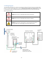
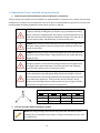
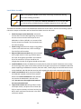
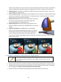
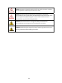
™
Pika T701 Turbine
Installation & Service
Manual
pika-energy.com
TC1317 Installation and Service Cover.indd 1
6/5/15 11:22 AM
Installation &
Service Manual
Revision 1.4
Turbine Serial #_______________
Turbine Serial Number
The serial number of the turbine is stamped or scribed into the nacelle casting at the base of the tail pocket. The
serial number is required to simplify repair and maintenance. The serial number is also recorded on the inside
cover of the manual for future reference.
Revision Table
Revision
Date
Changes
1.0
1.1
1.2
1.3
1.4
2013-11-21
2014-01-30
2014-03-18
2014-04-28
2015-04-02
Initial release
Blade rotor assembly
Formatting and diagram updates
Diagram updates
Brake locking screw removal and plug screw installation; updates for
installation checklist, specification table, wiring diagrams, off-grid
applications, lifting line redirection load warning, yaw attachment, tools
checklist, operations, troubleshooting and maintenance sections added.
1
Contents
INTRODUCTION ........................................................................................................................................ 4
Symbols used in this document ............................................................................................................................. 4
Turbine Specifications ........................................................................................................................................... 4
1 TURBINE OVERVIEW ............................................................................................................................... 5
What is REbusTM? ................................................................................................................................................... 5
2 TURBINE SYSTEM DESIGN ........................................................................................................................ 6
2.1 Applications ..................................................................................................................................................... 6
Grid-Tie Wind System: ....................................................................................................................................... 6
Grid Tie Wind/PV Hybrid System:...................................................................................................................... 6
Off-grid Wind System: ....................................................................................................................................... 6
Off-grid Wind/PV Hybrid System: ..................................................................................................................... 6
Other system designs ........................................................................................................................................ 6
2.2 Siting and Towers ............................................................................................................................................ 7
Guyed Towers .................................................................................................................................................... 7
Freestanding Towers ......................................................................................................................................... 7
Foundations and Anchoring .............................................................................................................................. 8
Unconventional Mounting Situations ............................................................................................................... 8
2.3 REbus™ DC wiring, grounding, and lightning protection system .................................................................... 9
Grounding and Lightning Protection ............................................................................................................... 10
3 T701 TURBINE INSTALLATION ................................................................................................................ 11
3.1 Turbine Mechanical Diagram ........................................................................................................................ 12
3.2 Wiring Diagrams ............................................................................................................................................ 13
3.3 Foundation, Tower, and field wiring installation .......................................................................................... 14
3.4 Prepare to Install the Turbine........................................................................................................................ 16
Use of checklists .............................................................................................................................................. 16
Materials Checklist .......................................................................................................................................... 16
Turbine Packing List ......................................................................................................................................... 17
Tools Checklist ................................................................................................................................................. 17
Copy of Turbine Installation Checklist ............................................................................................................. 18
Summary of Fastener Torque Specifications ................................................................................................... 19
2
3.5 Turbine assembly........................................................................................................................................... 20
Build Blade Assembly....................................................................................................................................... 20
Attach Nacelle to Tower Top ........................................................................................................................... 22
Wire the Brush Disk ......................................................................................................................................... 24
Install Blade Assembly ..................................................................................................................................... 26
Install Tail Assembly and Shroud ..................................................................................................................... 27
3.6 Complete connections and perform pre-flight checks .................................................................................. 28
3.7 Raising and Securing the Tower .................................................................................................................... 29
4 COMMISSIONING THE TURBINE ............................................................................................................... 31
5 TURBINE SYSTEM OPERATION (GRID-TIE) ................................................................................................. 32
5.1 How to Use the Front Panel Display .............................................................................................................. 32
5.2 Turbine Startup .............................................................................................................................................. 32
5.3 Normal Operation.......................................................................................................................................... 32
Light Winds ...................................................................................................................................................... 32
Moderate Winds .............................................................................................................................................. 33
High Winds ...................................................................................................................................................... 33
5.4 Power Outages .............................................................................................................................................. 33
5.5 Manually disabling the turbine...................................................................................................................... 33
6 INSPECTION AND MAINTENANCE ............................................................................................................. 35
6.1 After first month of operation: ...................................................................................................................... 35
6.2 Monthly: ........................................................................................................................................................ 35
6.3 Annually: ........................................................................................................................................................ 35
6.4 Every 10 years of operation (5 years in high wind site): ............................................................................... 35
6.5 End-of-life: ..................................................................................................................................................... 35
7 STATES, FAULTS AND ERRORS ................................................................................................................. 36
7.1 States ............................................................................................................................................................. 36
7.2 Faults ............................................................................................................................................................. 36
7.3 Errors ............................................................................................................................................................. 36
7.4 Backup Safety Brake ...................................................................................................................................... 36
8 TROUBLESHOOTING.............................................................................................................................. 38
3
Introduction
Congratulations on your purchase of the T701 wind turbine! This manual will guide the installer through proper
installation and setup of the Pika Energy T701 turbine, as well as maintenance and troubleshooting of the unit.
It is important to carefully and thoroughly read the entire manual in a comfortable setting, before venturing
out in the field to install the turbine.
Symbols used in this document
Throughout the manual, the following symbols highlight important information:
DANGER: Hazards that could cause death or serious injury
WARNING: Actions or situations that could permanently damage or destroy the
T701 turbine or other system components
NOTE: Helpful tips and points of interest
CHECKMARK: installation checklist requires a check at this step
TAKE A PHOTO: installation manual requires a photo at this step
EARTH GROUND: Relates to proper grounding of the system, critical for safety and
lightning protection.
Turbine Specifications
Parameter
Turbine Type
Rotor diameter
Swept area
Blade type
Speed control
Redundant control
Towertop mass
Rated power (approx.)
Peak power
Annual output (approx.)
Cut-in windspeed
Survival windspeed
Turbine electrical output
Electrical parameters
REbus Power
REbus voltage
REbus current
Value
3-blade HAWT, upwind free yaw
3.016 m
7.01 m2
Optimum twist-taper injection-molded glass-reinforced polypropylene resin
Digitally-controlled alternator torque
One-shot centripetal overspeed brake
45 kg
1500W @ 11 m/s
1700W @ 13 m/s
2,420 kWh at 5 m/s avg. (Rayleigh)
3.3 m/s
60 m/s
REbus™ DC microgrid: regulated +/-190VDC
Nominal (Maximum)
1575 W (1785 W)
380 V (420 V)
4.7 A (6.7 A)
4
1 Turbine overview
The T701 turbine is a horizontal-axis, three-blade, passive-yaw upwind turbine with a rotor diameter of 3.0
meters and a peak output of approximately 1.7kW. The turbine features high-performance molded blades and a
quiet, efficient permanent-magnet alternator. Rotor speed is maintained within a safe operating range by the
alternator through active load control, with an exclusive patent-pending mechanical overspeed brake that is
entirely independent of the primary load control. The basic elements of the T701 wind turbine are illustrated
below.
The T701 turbine produces a regulated DC current output, and is designed exclusively for connection to a REbus
DC microgrid. REbus is an advanced DC microgrid platform developed by Pika Energy for small-scale wind, solar,
and hybrid systems. Read and understand the accompanying REbus Microgrid Introduction and Design Guide
for more information on setting up a REbus microgrid.
DANGER: The REbus microgrid operates with a differential voltage of up to 420
VDC. The T701 turbine incorporates advanced safety features; however, like
120/240VAC home wiring, the REbus presents the hazard of potentially lethal
voltages. All wiring should be performed up to local code standards by a fully
licensed and properly trained electrician.
WARNING: Do NOT attempt to connect the turbine directly to AC wiring permanent damage may result. Do NOT attempt to connect the turbine directly to
a low-voltage DC system (e.g. 12VDC, 24VDC, 48VDC). The T701 turbine should
only be connected to a properly installed and tested REbus microgrid. Read and
understand this manual AND the accompanying REbus Microgrid Design and
Installation Manual before attempting to install the T701 turbine.
NOTE: Pika Energy recommends storing this manual in a sealed waterproof
container located near the inverter for ready access.
What is REbusTM?
The underlying technology behind Pika Energy’s X3001 Inverter is an innovative energy management platform or
‘smart microgrid’ called REbus™. REbus™ is a DC energy network that operates alongside the existing AC
infrastructure, enabling customers to build cost-effective, scalable renewable energy systems. The REbusTM
network is designed to serve as an open interconnection standard for networking next-generation energy
technology – like Wi-Fi or USB for green energy.
5
2 Turbine System Design
To give good performance, the T701 turbine must be installed as part of a well-thought-out system, designed in
accordance with industry best practices.
2.1 Applications
Grid-Tie Wind System:
T701 Wind Turbine + X3001 REbus Inverter
The T701 turbine is connected to the building wiring and the AC grid through a REbus™ inverter, such as Pika
Energy’s X3001. This converts the turbine’s REbus DC output to standard 60 Hz AC current for use in your
home’s appliances. If extra energy is available, the inverter automatically feeds the power back into the grid.
Unlike other inverters, Pika’s X3001 REbus inverter provides the ultimate in system design flexibility, enabling
multiple turbines or a combination of wind and solar to feed directly into the inverter. More information is
available in the inverter manual and REbus Microgrid Introduction and Design Guide
Grid Tie Wind/PV Hybrid System:
T701 Wind Turbine + S2001 PV Link + X3001 REbus Inverter
Pika Energy offers a PV hybrid option with unmatched performance and flexibility. Up to 8 standard PV modules
can be connected to the X3001 inverter in parallel with the T701 turbine through Pika’s S2001 “PV Link”
maximum powerpoint tracking converter. Contact Pika Energy for more information about this exciting option
for boosting the performance of the T701 turbine system with solar photovoltaics.
Off-grid Wind System:
T701 Wind Turbine + B801 REcharge Battery Charge Controller
The T701 Wind Turbine can be used in off-grid applications when combined with a REbus B801 Battery Charge
Controller. Contact Pika to learn more about charge controller options that are currently available.
Off-grid Wind/PV Hybrid System:
T701 Wind Turbine + S2001 PV Link + B801 REcharge Battery Charge Controller
Pika Energy offers a wind and PV hybrid option with unmatched performance and flexibility for off-grid
applications. The T701 Wind Turbine can be combined with 3-4 kW of PV (12-16 standard PV modules) in offgrid applications when combined with a REbus B801 Battery Charge Controller. Contact Pika to learn more about
charge controller options that are currently available.
Other system designs
The REbus microgrid is designed to be a very flexible infrastructure that allows many configurations including
multiple wind turbines on the same inverter. See the REbus Microgrid Introduction and Design Guide for more
details
6
2.2 Siting and Towers
DANGER: Obtain training from the tower manufacturer before attempting to
install a tower or turbine. See Section 3 ‘T701 Turbine Installation’ for important
tower safety information.
DANGER: Do not climb any tower without manufacturer-approved safety
equipment. Never climb a tower that was not designed to be climbed. Carefully
inspect the tower and all safety equipment before climbing.
WARNING: Because the dynamic interaction between the tower and the turbine
can cause damaging vibrations, the T701 turbine must be installed on a Pikaapproved tower. Failure to use a tower approved in writing by Pika Energy will void
the turbine warranty.
The most important factor in the performance of any wind turbine is the quality of the wind resource at the
location of the turbine. Just as solar panels must be installed in a sunny location, wind turbines must be installed
where there is unimpeded access to a good wind resource. One of the most common causes of poor
performance is installation on a tower that is too short. For acceptable performance the tower must be at
least 10 meters (30 feet) taller than surrounding obstacles within a 100m (300 ft) radius. This is a minimum
requirement, and more height exposure is better. Remember that trees grow rapidly in height, and are likely to
significantly decrease the wind exposure of nearby turbines over a few years. If in doubt, choose a taller tower.
There are two basic types of towers, guyed and un-guyed towers. In either case, access to the turbine for service
is an important consideration. Pika Energy strongly recommends the use of tilt-up or climbable towers, in case
the turbine requires service. Fixed, non-climbable towers significantly increase the cost of inspection and repair.
Guyed Towers
Guyed towers are supported at intervals by cables (guy wires), which help the tower withstand side loading from
the wind. Guyed towers require more open space than freestanding towers, but are more structurally efficient,
so they are often lighter and less expensive than monopole towers for a given height. Depending on soil
conditions, guyed towers can often be installed without concrete. The anchoring system required for each guy
depends on the turbine size and soil conditions. Common anchors include screw-in earth augers, expanding
anchors, and poured-in-place concrete anchors. The central column will typically sit on a light metal spreader
base or a small concrete pad.
Some guyed towers are designed to be tilted into place using a gin pole; others are designed to be raised with a
crane, with subsequent maintenance performed by climbing.
Freestanding Towers
Freestanding towers support both the weight of the turbine and the sideways force of the wind through the
strength of the tower itself. Freestanding towers require significantly less open space than guyed towers, but
will likely be heavier and require a more substantial foundation – typically cast-in-place reinforced concrete. Just
7
as the trunk of a tree must be larger near the ground than at the top to withstand the force of the wind,
freestanding towers nearly always taper, being smaller at the top and largest where they connect to the ground.
Common types of freestanding towers include the tapered tubular monopole and the open tapered lattice type.
Monopole type towers present a cleaner appearance, but may be heavier than an open lattice type tower. Many
freestanding towers may be raised with a winch and gin pole.
Foundations and Anchoring
A tower is only as secure as its foundation. Follow the tower manufacturer’s instructions in all cases when
installing a foundation. Ensure the correct grade, size, and placement of reinforcing bars (‘rebar’), use the
recommended grade of concrete, and the correct reinforcing fiber if specified. Concrete must be tamped or
vibrated per the instructions of the tower designer. Excavated soil must be tamped back into place per the
tower manufacturer’s recommendations, particularly when installing expanding (e.g. “bust”) anchors, which
depend on well-compacted soil for much of their holding power.
Observe tower manufacturer recommendations for installation on sloped sites. Non-planar (lumpy) sites are
especially dangerous for guyed towers. Raising a tilt-up guyed tower on a convex site can result in rapidly
increasing guy tension as the tower is raised, resulting in catastrophic collapse via buckling. Raising a tilt-up
guyed tower on a concave site can result in slack guy lines, leading to an unsupported tower and catastrophic
collapse.
Unconventional Mounting Situations
Historically, the best-performing wind turbines are installed on ground-mounted towers in open, exposed
terrain. Pika Energy strongly advises against mounting a wind turbine directly to the structure of a home.
Failure to use a Pika-approved tower will void the turbine warranty. Building-mounted wind turbines have a
history of poor performance, noise issues, and significant downtime. Consult with an experienced structural
engineer before mounting a T701 turbine to a steel or reinforced-concrete commercial building, to address
structural issues, noise, vibration, and potential leaks. Attachment to a building does not substitute for a tower!
Poor performance is virtually guaranteed if the turbine does not project at least 10 meters above surrounding
obstacles (including buildings) within a 100m radius.
8
2.3 REbus™ DC wiring, grounding, and lightning protection system
The T701 wind turbine features Rebus, a plug-and-play microgrid standard developed by Pika Energy. See the
accompanying REbus Microgrid Introduction and Design Guide and REbus Quickstart Guide for important
information before designing your REbus system. Contact Pika Energy regarding availability of additional REbus
microgrid products to expand your home energy system.
All site wiring must be installed and grounded in accordance with local building codes. Local codes may require a
disconnect or other additional safety hardware.
For most applications 12-14 AWG wire is appropriate. For installations with very long wire run distances (greater
than 1000 feet), 10 AWG wire is recommended to reduce energy losses. The following tables indicate wire sizes
needed for varying average wind speeds and run lengths. The indicated run length is the measured distance
along the path of the wire from the inverter to the turbine, and should include the height of the tower. Note
that the total wire length will be 2X this distance. The tables below are for a single turbine installation; consult
Pika Energy for wiring requirements for dual-turbine and hybrid systems.
2% Energy Loss Table: Wire gauge for less than 2% loss (one-way wire length vs. average wind speed)
5m/s
6m/s
7m/s
100m
328ft
14
150m
492ft
14
200m
656ft
14
250m
820ft
12
300m
984ft
12
350m
1148ft
12
400m
1312ft
10*
14
14
14
14
12
12
12
12
10*
10*
10*
10*
10*
10*
4% Energy Loss Table: Wire gauge for less than 4% loss (one-way wire length vs. average wind speed)
5m/s
6m/s
7m/s
100m
328ft
14
14
14
150m
492ft
14
14
14
200m
656ft
14
14
14
250m
820ft
14
14
14
300m
984ft
14
14
12
350m
1148ft
14
12
12
400m
1312ft
14
12
12
*NOTE: The T701 wind turbine can only accept 12-2+g or 14-2+g AWG type UF
(“Underground Feeder”) wire through the yaw into the nacelle. If 10 AWG wire is
used to get from the inverter to the tower base because of a very long wire run
distance, it should be transitioned at the tower base to 12-2 or 14-2 AWG type UF
wire in a junction box.
9
Grounding and Lightning Protection
Turbines, towers, and inverters must be securely connected to earth ground per manufacturers’ instructions. At
a minimum, the tower should be grounded at its base by an eight foot long copper-clad steel grounding rod
driven vertically into the soil and bonded securely to the tower. Non-conductive towers require a heavy-gage
copper ground wire connecting the steel towertop flange with the foundation grounding system.
NOTE: Grounding turbines in arid regions presents special challenges. In many
cases the standard grounding rod will not provide a sufficient low-resistance path
to earth ground where soil is dry. Consult experienced electrical professionals in
your area for best practices.
Pika Energy recommends the use of lightning arrestors at the tower base and inverter, to prevent damage from
lightning. However, no protection system can entirely eliminate the risk of damage from a direct lightning strike.
Pika Energy recommends the use of the Midnight Solar MNSPD-300-DC Surge Protection Device (or equivalent)
for protection on all REbus devices. The surge protection device should always be installed as close as possible
to the hardware it is intended to protect.
Figure 2.1 – Midnight Solar MNSPD-300-DC Surge Protection Device wiring diagram:
10
3 T701 Turbine Installation
The T701 turbine has been designed to be fast and simple to install. However, it is important to carefully follow
the instructions in this manual as well as the tower manufacturer’s manual.
DANGER: Do not install a T701 turbine unless you have read this entire installation
manual and watched Installing the Pika Energy T701 Turbine, available at
http://vimeo.com/104006485.
DANGER: Always wear appropriate OSHA-approved Personal Protective
Equipment, including Hard hat, Steel-toed boots, Safety Glasses, Gloves
DANGER: Pika Energy does not recommend working alone when installing or
servicing turbines or towers.
WARNING: Never remove the front plate unless specially trained in alternator
service. The T701 alternator contains powerful magnets which may cause tools
and fasteners to fly and shatter. The magnets also attract metal particles from
clothes, skin, and hair, and these particles may damage the alternator. Credit cards
or other forms of magnetic storage may be erased or irreparably damaged if
brought in close proximity to the alternator.
NOTE: Professional or third party installers are required to go through Pika training
before installing the T701 turbine for customers.
USE THE CHECKLIST: A signed, completed checklist with the required photos must
be filed with Pika Energy for warranty registration.
TAKE PHOTOS: Photos of key installation steps are required for warranty
registration.
11
3.1 Turbine Mechanical Diagram
DO NOT CONNECT THE T701 TURBINE
DIRECTLY TO AC POWER!
DO NOT CONNECT THE T701 TURBINE
DIRECTLY TO BATTERIES!
+
~
AC
-
BATTERY
12
3.2 Wiring Diagrams
The following wiring diagram is for the basic system design including a T701 Wind Turbine and a X3001 REbus
Inverter. For other system configurations, consult the REbus Microgrid Design and Installation Manual. Under
no circumstances should a T701 Wind Turbine be connected directly to AC or DC sources/sinks other than
REbus-compatible devices.
DANGER: Never connect a T701 Wind Turbine directly to AC wiring.
DANGER: Never connect a T701 Wind Turbine directly to a battery.
WARNING: Do not install a ‘shorting switch’ across the output of the turbine.
Shorting the REbus may cause damage to the turbine and/or inverter.
13
3.3 Foundation, Tower, and field wiring installation
1. Install the tower and foundation per tower manufacturer’s instructions.
The Pika Energy T701 turbine must be installed on an approved tower. If questions arise, consult with the tower
manufacturer’s customer service department. Be sure to observe recommended curing times for concrete, and
carefully backfill and tamp disturbed soil around earth anchors as required.
DANGER: Raising, climbing, and working around towers exposes workers to a
number of hazards, including but not limited to injury and death from falling
objects, recoil from snapping cables, pinch points, and spinning blades. Do not
install the T701 wind turbine without professional training. In all cases, do not
rush, but work carefully and deliberately, and use common sense.
DANGER: No personnel should stand within the drop zone of the tower while
the tower is being raised or lowered, and bystanders should be held far back
from the turbine area.
DANGER: Pika Energy strongly recommends against the use of over-the-road
vehicles to raise or lower towers. A high-quality winch with ample load rating
should be used.
DANGER: Refer to the tower manufacturer’s documentation to determine the
raising line tension. In most cases the raising line tension will be greater than
the weight of the turbine and tower. Ensure that the winch has a Working
Load Limit (WLL) greater than the raising line tension.
DANGER: Redirection links (blocks and pulleys) used in a lifting line system
can be subjected to total loads greatly different from the lifting line tension.
The total load varies with the angle between the incoming and departing lines
to the redirection equipment. Ensure that ALL links in the tower raising
system have a Working Load Limit (WLL) greater than the raising line tension
multiplied by the angle factors listed in the table below.
Angle Factor Multipliers for Redirection Links
Angle ( )
Factor
Angle ( )
Factor
0⁰
2
60⁰
1.73
30⁰
1.93
90⁰
1.41
45⁰
1.84
120⁰
1
2. Test-raise the tower before installing the turbine.
NOTE: Pika Energy strongly recommends raising the tower without the turbine
installed, prior to installation of the turbine. This puts less hardware at risk in case
of a malfunction.
14
Pika Energy recommends the use of a heavy-duty worm-drive (non-backdrivable) winch with a Working Load
Limit (WLL) greater than the maximum raising line tension. Check the duty cycle rating on the winch to be used,
as many consumer-grade bumper winches are not rated for continuous duty, and may overheat if used for more
than a few seconds at a time.
DANGER: Be aware that some equipment (including hardware intended for rock
climbing) is rated by the actual failure strength, rather than working load. Confirm
the Working Load Limit of all load-line elements before raising the tower.
3. Lower the tower nearly to the ground, and prop it up on a sturdy support (such as a strong sawhorse)
at a comfortable working height, at least 36” off the ground.
4. Install Field Wiring and grounding system per the wiring diagram above. Install at least one grounding
rod at the tower base. Pika Energy recommends installation of a high quality lightning arrestor at the
tower base. A junction box may be mounted to the tower foundation, if none is provided by the tower
manufacturer. Local codes may require a DC disconnect (380VDC rated) at the tower base, or at another
location between the turbine and the inverter.
NOTE: Pika Energy has observed that mice, snakes, and other small animals love
the dry, protected spaces inside tower bases and wiring boxes. Pika recommends
filling all unused knockouts with metal plugs, and stuffing stainless steel wool in
any openings ¼” in diameter or greater.
5. Install chafing gear on tower wire. Pika Energy recommends the use of chafing gear to protect the wire
from sharp edges that may exist inside the tower. Chafing gear may be improvised by applying short
sections of tubular foam pipe insulation to the wire, and securing with high-quality electrical or duct
tape, before fishing the wire through the tower. Pay special attention to the area where the wire passes
through the base of a tilt-up tower. In many situations it is necessary to run the tower wire through a
short stretch of flexible conduit at the base of the tower to adequately protect it during tower
raising/lowering.
NOTE: The REbus wiring that runs in the tower may be installed in the tower either
before or after installing the turbine to the tower, depending on which approach is
more convenient.
WARNING: The T701 turbine features an integrated cable clamp in the wiring
compartment (under the blue shroud), which is designed to clamp 12-2+g or 142+g UF (underground feeder) wire. Attempts to use types of tower wire other than
type “UF” may result in the wire slipping through the clamp, or the clamp crushing
the wires, leading to an open circuit, short circuit, or other dangerous condition.
15
6. Pull tower wire through tower.
Take care to avoid pinching or damaging the wire while installing the turbine. Leave at least 2’ of wire projecting
from the top of the tower. The REbus wiring that runs in the tower may be installed in the tower either before or
after installing the turbine to the tower, depending on which approach is more convenient. If pulling wire after
installing the turbine, feed a fish tape down through the yaw and pull the wire from below.
7. Install a Towertop Adapter if
necessary to provide a 2.5” male NPT
(national pipe thread) at the
towertop. Follow manufacturer’s
instructions; use loctite or locking
fasteners on all fasteners unless
specifically advised otherwise.
3.4 Prepare to Install the Turbine
Use of checklists
Pika Energy strongly recommends using checklists to ensure that the installation is efficient and complete. The
installation checklist and associated installation photos are mandatory for warranty coverage.
Materials Checklist
Got it! Component
Comment
T701 Turbine (3 boxes)
B801 REcharge Battery Charge Controller
X3001 REbus inverter/converter (or other Pika inverter)
Tower adapter (including hardware)
Tower wire - UF 2+g (underground feeder)
Chafing protection for tower wire
Duct tape
1” conduit and fittings
5 feet of flexible 1” conduit
Ground rod(s)
4 AWG grounding wire, clamps and lugs
grounding wire of same guage as tower conductors
Lightning arrester(s)
6”x6” junction box
Wire nuts
Circuit breaker (for inverter installations)
Red and blue electrical tape
16
Turbine, blades, tail vanes
for off-grid systems
for grid-tie systems
if needed, depending on tower type
see table on page 9 for minimum AWG size
½” pipe insulation is good
for securing chafing protection
for trench and connection to inverter
for wire coming out of tower base
if not supplied with tower
if not supplied with tower
for grounding tower to lightning arrester
in nacelle box
for lightning arrester at tower base
for connecting lightning arrester
see inverter manual for correct size
for wiring the brush puck and lightning
arrester
Turbine Packing List
The standard T701 shipment consists of three packages. Please verify that all three packages are complete
before beginning the installation.
Nacelle Package contents:
Got it! Nacelle Package
Nacelle assembly
Blade hub
Manuals
Hardware kit
Lightning arrester
Got it! Blade Package
3 blades
Tail boom
Nose cone
Tools Checklist
Got it! Tool
Personal Protective Equipment (PPE) including
hardhats, safety glasses, gloves, and steel-toed
boots
Digital camera
Sawhorse, cribwork, or other tower support
#2 Phillips Screwdriver
Chain Wrench, 4.5” capacity or 3.5” pipe wrench
with cheater bar
Second pipe or chain wrench
Fish tape
Messenger line
Utility knife
Wire strippers
Needlenose pliers
Metric ratchet, ⅜” drive or larger
Ratchet extension
Metric sockets (10mm, 13mm, 19mm)
Torque wrench (5-65 ft-lb)
Torque screwdriver (4-15 in-lb.)
Metric allen wrench set
Got it! Tail Vane Package
Fore tail piece
Aft tail piece
Comment
For photo documentation for warranty
24” minimum length for torqueing yaw onto tower
top.
For counter torque on tower adapter during yaw
tightening
For fishing tower wire though assembled tower
For pulling wire through conduit to inverter
For turbine assembly
Required for tail boom attachment
For turbine assembly
For turbine assembly
For turbine assembly
Ball-end preferred for brake locking screw removal
and plug installation (6mm hex key)
Flashlight
Light cord (3/32”) or string
for pulling wire through tower and for prusik knots
for pulling on guys wires.
For tower anchor layout
Refer to tower installation manual
Winch/ grip hoist, anchoring chain for lifting device,
shiv, shackles
For working on the ground under blade rotor
For repairing damaged threads etc.
Wooden stakes or flagging
Tower installation tools
Tower raising equipment
Tarp or other ground cover
Round, flat, and triangle files
17
Copy of Turbine Installation Checklist
Submission of a properly completed checklist and the 8 required photos is mandatory for warranty coverage.
Name of Owner:
Installation Address:
Turbine serial number:
Tower Make/Model and Notes:
Mailing Address if Different:
Wireless Router Make/Model:
Circle One: Broadband Satellite Dial-Up HotSpot
Phone:
Installation Finish Date:
E-mail:
Name of Installer:
Initials
Step Description
Install tower and foundation per manufacturer’s instructions
15 blade bolts torqued to 25 Nm (18 ft-lb)
Yaw threads tightened 1-2 turns past hand tight
Yaw jam screw torqued to 18 Nm (13 ft-lb)
PHOTO of yaw, showing threads and set screw
Brake locking screws removed and replaced with plug screws
PHOTO of plug screws in the place of brake locking screws
2 clamp bar screws torqued to 0.4 Nm (4 in-lb)
3 tower wire leads torqued to 1.5 Nm (13 in-lb)
PHOTO of brush block, showing completed wiring
Blade bolts re-torqued to 25 Nm (18 ft-lb) at least 30 minutes after initial tightening
2 PHOTOS of blades installed on hub (1 photo for each side)
Hub nut installed with Loctite and torqued counterclockwise to 76 Nm (56 ft-lb)
PHOTO of nut, washer and blade assembly on shaft
Nosecone screws attached and torqued to 0.4 Nm (4 in-lb)
Tail vane nuts torqued to 7 Nm (5 ft-lb)
Tail boom bolts torqued to 25 Nm (18 ft-lb)
Shroud attach screws installed and torqued until rubber bulges slightly
Spin test procedure completed per instructions
Turbine started up and ran normally
PHOTO of the completed turbine installation (from the gin pole side)
PHOTO of the tower base after completion of turbine installation
Comment
I certify that this installation was performed in accordance with the T701 Turbine Installation manual.
Signed________________________
Date__________________________
Please use this box to provide suggestions to improve Pika’s products. Thank You!
18
Summary of Fastener Torque Specifications
The following table of fastener torques is provided for the convenience of the installer. This table is not a
replacement for the full assembly instructions on the following pages. When tightening, DO NOT GUESS. Use a
torque wrench.
Component
Yaw casting
Fastener
type
2½” NPT
Yaw jam
screw
M8 set
screw
Wire clamp
bar screws
Tower wire
leads
Blade-hub
M4 pan
head
M4 truss
head
M8 bolt
Bladehub
retention nut
Nose cone
screws
Tail vane
nuts
M12 lefthand
M4 truss
head
M6 pan
head +
nylon-insert
nut
M8 hex cap
screws
M4 truss
head
Tail boom
bolts
Shroud
attach
screws
Tools needed
Torque (Nm)
at least a 24” chain
wrench and a 3” pipe
wrench with extension
to oppose torque on
the tower
4mm hex-bit socket
(preferred)
or 4mm hex wrench (
#2 phillips
Apx. 540 – hand tighten the yaw while
someone supports the weight of the
turbine. Then apply 200 pounds of force at
the end of a 24” wrench until the yaw will
not tighten any further.
18
0.4
#2 phillips
1.5
13mm socket
25 (re-torque at least ½ hr after initial
tightening)
76
18
0.4
19mm socket, small hex
or screwdriver
#2 phillips
Torque
(ft-lb)
Apx.
400
13
0.3 (4
in-lb)
1.1
56
10mm socket and #3
phillips
7
0.3 (4
in-lb)
5
13mm socket and
extension
#2 phillips
25
18
Apply hand pressure to shroud to help seal against
gasket. Tighten until rubber washer bulges slightly (see
instructions on page 28)
WARNING: Be sure to tighten the yaw to the tower adapter with at least 200 pounds of force
at the end of a 24” wrench while sufficient counter torque is being applied to the tower by a
crew member, to prevent the tower from rotating. Failure to properly torque the yaw could
lead to the turbine falling off the tower.
19
3.5 Turbine assembly
Before beginning the installation, carefully unpack
and verify the contents against the nacelle box and
remove the hardware kit, verifying that all
components of the packing list are present. The T701
turbine ships in 3 boxes - one for the nacelle, one for
the blades and tail boom, and one for the tail vanes.
Build Blade Assembly
NOTE: Trailing edges of blades can be sharp. Pika Energy recommends wearing
gloves while handling the blades.
The blade-hub assembly should be completed before assembling other turbine components to allow for
adequate time for a two-step blade bolt torqueing procedure. Perform the following steps to assemble the
blades and hub:
NOTE: Gentle manual pressure may be required to fit the blade to the hub, but if
excessive force is required, remove the blade and check the assembly for issues.
WARNING: Dirt or grit on the greased main shaft and blade hub shaft bore surfaces
can damage those precision surfaces. Assemble the blade rotor on a clean surface
and, if necessary, use tape to mask off the blade hub bore.
1. Unpack the blades from the blade box. Use caution to prevent
damage, especially to the thin trailing edges of the blades.
Blades come from the factory pre-balanced. The order of the
blades does not matter.
2. Unpack the nacelle and remove the blade hub from the main
shaft. It’s very important that the greased surfaces on the main
shaft and in the blade hub bore do not pick up dirt or grit. Use a
clean sheet of cardboard or tarp to assemble the blade rotor on
to keep the hub out of the dirt. If the wind is blowing dirt into
the work area, it may be necessary to protect the blade hub by
masking the shaft bore with tape.
3. Orient the blade hub so that the side with three-lobed spline
around the shaft is facing up.
4. Assemble blade to hub: Begin assembly by carefully fitting the
three large holes on the blade to three bosses on the hub. It
does not matter which blade goes in which position. Firm
gentle pressure should seat the bosses fully in the mating holes. Do not force the blades onto the hub.
20
5. Install the two long downwind blade bolts, paying careful attention to the order of the
washers. Put the conical washer on the bolt first with the cone side pointed toward the
head of the bolt (see image below). The flat washer goes on the bolt after the conical
washer. Install the two 80mm M8 bolts and washers. Tighten the bolts just enough to
ensure that the blade is fully seated on the hub, but wait to fully torque the bolts until all
of the blade bolts have been installed.
NOTE: Proper orientation of the conical (Belleville) washer is critical. Be sure the
cone (convex) side is pointed toward the head of the bolt.
6. Repeat for two more blades.
7. Flip the assembled rotor over. Use caution when flipping the rotor to avoid damaging
the thin trailing edges or tips of the blades.
8. Install and torque three short upwind blade bolts. Insert three 25mm M8 bolts,
paying close attention to the order and orientation of the washers. Put the conical
washer on the bolt first with the cone side pointed toward the head of the bolt. The
flat washer goes on the bolt after the conical washer. Torque each bolt to 25 Nm (18
ft-lb) with a reliable torque wrench.
9. Take photo: Take a digital photo of the upwind side of the blade rotor.
10. Flip the assembled rotor over for a second
time to access the previously installed bolts
for proper torqueing. The blade rotor should
be supported near the blade tips as shown in
the image to the right. This allows for the
downwind edge of the blade root opening to
bear against the hub. Torque to 25 Nm (18 ftlbs).
11. Take photo: Take a digital photo of the
downwind side of the completed blade
assembly.
12. Set the assembled rotor aside in a safe place.
21
The torque on the blade bolts will need to be checked again at least 30 minutes after the initial
torqueing, but for now set the assembled blade rotor aside in a safe place where it won’t get dirty or
damaged during the next steps.
TAKE A PHOTO: Take digital photos of the upwind and downwind sides of the
completed blade assembly.
Attach Nacelle to Tower Top
1. Check cable length: Ensure that at least 24” of tower cable extends beyond the top of the tower.
2. Remove the rear shroud (blue) from the turbine and carefully set it aside. The rear shroud is secured
with tape for shipping. Exercise caution to prevent damage to the control circuit board.
WARNING: the control circuit board contains fragile components that can be
damaged by rough handling. Avoid contact with the circuit board or its
components. Two people should handle the nacelle to prevent damage.
3. Remove the bladehub from the mainshaft and carefully set it aside. Avoid getting dirt inside the
mainshaft bore.
4. Position the nacelle: Taking care not to pinch or damage the wire, lift the nacelle and position the
threaded socket of the yaw casting near the towertop. Two people should handle the nacelle to prevent
damage to the circuit board.
5. Feed the tower wire: Pass the free end of the tower wire upward through the hole in the yaw casting,
feeding any loop or excess slack through the yaw. Ensure that the wire is not twisted, kinked, or
jammed. It may be necessary to guide the wire past the curved
strain relief bracket.
6. Thread yaw onto tower: Position the socket of the yaw casting
over the threaded top of the tower and rotate the yaw gently to
engage the thread. One person must support the weight of the
turbine, while another adjusts the alignment and threads the
parts together. The yaw should rotate 4-5 full turns by hand, so
long as the bulk of the turbine’s weight is supported to prevent
jamming. Ensure that the tower wire rotates freely within the
yaw casting to prevent excessive twist.
WARNING: Take care to ensure that the yaw is not cross-threaded on the towertop.
7. Wrench-tighten the yaw: Once the threaded engagement is hand-tight, tighten using a chain-type pipe
wrench at least 24” in length and apply 400 foot pounds of torque. This is the equivalent of a 200lb.
person putting all of their weight on the end of a 24” wrench until the yaw stops threading onto the
tower. This should be 1½ to 2 turns beyond hand tight. If no member of the installation crew is heavy
22
enough, two people should work the chain wrench to ensure sufficient torque is applied. It will be
necessary to use a second wrench to apply opposing torque to the tower top to prevent the sections of
tower from rotating. A 3” capacity pipe wrench with an extension will be sufficient for a second person
to oppose the torqueing of the yaw.
WARNING: After torqueing the yaw on to the tower, check that the guy plates are
still properly aligned with the gin pole (if using a tilt-up guyed tower). Yaw torqueing
can result in inadvertent rotation of guy plates if tower sections are not held fast.
8. Tighten yaw jam screw: Once the yaw is secured to the tower, install the jam-screw from the hardware
kit. It threads into the tapped hole on the side of the yaw casting. Tighten the screw until it binds into
the tower top threads. Torque to 18 Nm (13 ft-lb). The jam screw has pre-applied threadlocker
compound to prevent loosening over time. Wipe off any excess grease from the threaded towertop.
NOTE: Consult Pika Energy before using a non-approved tower design.
TAKE A PHOTO: Take a digital photo of the towertop, yaw, and jam screw in
position
9. Take a Photo showing the connection between the
towertop and the yaw casting, and showing the yaw
set screw locked in place.
10. Remove the brake locking screws from the nacelle
and replace them with the provided plug screws (M8
x 12mm socket cap screws with pre-applied antiloosening compound) and rubber washers using a
6mm ball end hex wrench. The brake locking screws
ensure the overspeed brake does not accidentally
deploy during shipping. The brake locking screws
must be removed and replaced with the supplied
plug screws prior to installing the blade rotor.
TAKE A PHOTO: Take a digital photo of the plug screws installed in place of the
brake locking screws.
11. Take a Photo of the plug screws installed in place of the brake locking screws.
23
WARNING: The brake locking screws must be removed and replaced with the
supplied plug screws prior to installing the blade rotor. The blades will not rotate
with the brake lock screws in place.
Wire the Brush Disk
Once the turbine is secured to the top of the tower and the tower wire is in place, complete the tower wiring by
executing the following steps:
DANGER: Ensure that the tower wiring is de-energized before wiring the turbine.
WARNING: Be very careful not to damage the circuit board, especially when
attaching the wires to the brush disk.
NOTE: The T701 turbine features dual brushes on each channel of the turbine
output. There are six brushes, but only three conductors to wire.
1. Fit the tower cable: Form the tower cable carefully over the half-turn support on the strain relief
bracket, and mark the position of the cable clamp bar.
2. Strip outer insulation: Remove the cable clear of the strain relief bracket and carefully strip the outer
insulation back to ¼-½” beyond the mark with a sharp utility knife.
3. Secure wire under clamp: Re-position the wire over the strain relief bracket and tighten the 2 M4 panhead screws to secure the wire snugly to the bracket using the clamp bar. Alternate back and forth
between screws to ensure even clamping. Ensure that the clamp bar bears only on the gray wire
insulation, not the black and white insulation of the individual conductors. Torque the two M4 clamp bar
screws to 0.4Nm (4 in-lb). DO NOT OVER-TIGHTEN to prevent damage to wire.
24
4. Connect Ground Lead: Route
the bare copper ground wire to
the ground screw (marked with
the GROUND symbol), trim to
length, and form a clockwise
loop in the end of the wire, slip
the loop under the head of the
ground screw, and torque to
1.5Nm (1.1 ft-lb or 13 in-lb).
5. Connect Positive REbus Lead:
Mark the white wire with red
electrical tape, route it to the
“RE+” terminal, trim to length,
and strip approximately 20mm
(¾”). Form a clockwise loop in
the end of the wire, slip the
loop under the head of the
screw, and torque to 1.5Nm
(1.1 ft-lb or 13 in-lb).
WARNING: The T70 brush disk uses captive nuts with built-in anti-vibration locking features.
DO NOT use thread-locking compound. Common threadlockers (e.g. Loctite) contain
chemicals that will severely damage the polycarbonate brush block.
WARNING: Do not tighten, loosen, or adjust the brush fasteners (hex head screws closer to
center of brush block).
6. Connect Negative REbus Lead: Mark the black wire with blue electrical tape, route it to the “RE-”
terminal, trim to length, and strip approximately 20mm (¾”). Form a clockwise loop in the end of the
wire, slip the loop under the head of the screw, and torque to 1.5Nm (1.1 ft-lb or 13 in-lb).
7. Form wires within safe volume: Ensure that none of the three conductors extend beyond the diameter
of the brush disk, and that they do not extend above the top of the strain relief bracket. If necessary,
gently form the wires into place around the brush disk.
TAKE A PHOTO: Take a digital photo of the brush disk after wiring is complete.
8.
Take a digital photo of the completed brush disk wiring.
25
Install Blade Assembly
NOTE: Trailing edges of blades can be sharp. Pika Energy recommends wearing
gloves while handling the blades.
NOTE: The torque on the blade bolts must be rechecked at least 30 minutes after
the initial torqueing. All blade fasteners should be torqued to 25 N-m (18 ft-lbs).
The blade-hub assembly must be completed before attachment to the turbine. Perform the following steps to
recheck the torque on the blade rotor and install the blades onto the main shaft:
1. Check the torque on the blade bolts: At least 30
minutes after the initial bolt-tightening, use a torque
wrench to ensure that the bolt torque on all 15
blade bolts is 25 N-m (18ft-lbs). It is normal to find
that the torque has relaxed in the 30 minutes since
the initial torqueing.
2. Check O-ring: Check that the orange O-ring gasket is
in place in the shaft seal rotor, where it emerges
from the front of the turbine.
3. Wipe and lubricate mainshaft: Wipe the mainshaft
with a paper towel or clean rag, and then apply a
thin layer of the grease (provided in the hardware
kit) to the mainshaft. The layer should be thin
enough that the color of the grease should not be visible.
4. Install bladehub: Position the bladerotor assembly directly under the nacelle. Rotate the rotor to align
the three tangs of the spline on the turbine with the three gaps in the spline on the bladehub. With two
people supporting the bladerotor assembly from both sides, carefully align the mainshaft with the bore
on the bladehub, and slide the hub onto the shaft, engaging the spline and compressing the O-ring.
5. Install nut and washer: With one person holding
the bladerotor upward, install the thick stainless
washer and reverse-threaded M12 hub retention
nut onto the threaded stud in the end of the
shaft. Be sure to use the supplied red Loctite on
the reverse-threaded stud.
6. Torque hub retention nut: Using a 19mm socket
and torque wrench, torque the nut to 76 Nm (56
ft-lb). It may be necessary to insert a hex key (size
M5) or other small tool into the hole in the shaft
to prevent rotation.
26
NOTE: It may be necessary to insert a hex key or small screwdriver in the crossdrilled hole at the end of the shaft to prevent the shaft from spinning.
7. Double-check gasket: Check that the orange gasket O-ring is in place and compressed but visible around
the full diameter.
8. Take photos: Take digital photos of the assembled hub on the turbine, from upwind and downwind
directions.
TAKE A PHOTO: Take digital photos of the assembled hub on the turbine, from
upwind and downwind directions.
9. Install the nosecone by aligning the stepped features with the surface of the blades, then fine-tuning
the alignment of the holes in the nosecone with the threaded holes in the hub casting. Secure the
nosecone with three M4 truss-head screws from the hardware kit. Thread-locking compound has been
pre-applied to the screws. DO NOT use rubber washers on the nosecone. Torque the screws to 0.4 Nm
(4 in-lb).
Install Tail Assembly and Shroud
WARNING: It is critical to install both tail vanes. The turbine will not balance or
orient properly without a complete tail.
Install the tail assembly by performing the following steps:
1. Remove protective film: If protective film is present on
the tail vanes, peel it off and discard.
2. Assemble upwind vane to boom: Slide the crescentshaped tail vane into the slot in the tail boom and align
with the forward holes. Secure with two M6 phillips pan
head screws and nylon insert locknuts from the
hardware kit. Torque to 7 Nm (5 ft-lb).
3. Assemble downwind vane to boom: Slide the teardropshaped tail vane into the slot in the tail boom and align
with the rearward holes. Secure with two M6 phillips pan
head screws and nylon insert locknuts from the hardware
kit. Do not remove anti-seize tape that has been preapplied to the screws. Torque to 7 Nm (5 ft-lb).
4. Install tail assembly: Insert the tail boom into the tail
socket in the nacelle casting. The black rubber bulb gasket
should face upwards. Secure the tail to the nacelle with
two M8 hex bolts and small 8mm washers. Adjust the
27
5.
6.
7.
8.
9.
rotation of the tail boom to ensure that the tail vanes will be parallel with the tower when the turbine is
raised. Thread-locking compound has been pre-applied to the hex bolts. Torque to 25 Nm (18 ft-lb).
Stabilize yaw axis: Using stakes and light cord, stabilize the yaw axis to prevent rotation, in such a way
that the blades can still spin freely.
Check mainshaft rotation: Wearing gloves and standing clear of the swept area, rotate the blades slowly
by hand. You should feel a smooth resistance. If scraping, grinding, or squeaking sounds are observed,
stop and correct the issue before proceeding.
Position the shroud: Position the rear (blue) shroud loosely place
over the circuit board assembly, with the front edge of the
shroud downwind of the heat dissipation fins.
Align mounting holes: Using a flashlight, gently guide the rear
shroud into alignment with the four threaded holes in the nacelle
casting.
Install shroud fasteners: Install four M4 truss-head phillips
machine screws with black rubber gasket washers to secure the
shroud. Apply manual pressure to the shroud while tightening
screws to ensure that the shroud is well-seated. Tighten the
screws until the washers bulge slightly, but do not allow them to distort significantly or squirt out from
under the screw head.
3.6 Complete connections and perform pre-flight checks
NOTE: The following instructions are for installations with REbus inverters. For
some installations another REbus device (e.g. B801 charge controller) may be
used instead.
1. Read and understand T701 User Manual relating to turbine operating modes before raising the turbine.
2. Complete the connections between the turbine and the inverter before raising the tower, according to
the wiring diagrams. Observe all local and national code requirements.
3. Follow instructions in the REbus Microgrid Design and Installation Manual for DC wiring.
28
DANGER: Be sure to install the rear shroud before powering up the inverter or
REbus microgrid.
4. Once wiring is complete and all covers are in place, position the inverter circuit breaker to the ‘ON’
position. Toggle the power switch (on the bottom of the unit) to the ‘ON’ position to power up the
inverter.
5. Enable the inverter using the front panel display. Observe that the REbus microgrid voltage rises above
300V.
6. Scroll to the T701 Wind Turbine device page. Ensure that a new wind turbine device appears on the
inverter’s device list, it should be automatically added to the display if wired correctly. The wind turbine
should arrive from the factory disabled by default.
7. With the inverter enabled and the turbine disabled at the inverter front panel display, don gloves and
stand well clear of the swept area while rotating the blades slowly by hand. Significant resistance should
be felt, even at low speed.
8. Enable the turbine from the inverter front panel display. The blades should spin noticeably more freely.
Listen carefully for any clicking or scraping sounds while the blades spin. If the motion is not completely
smooth, do not raise the turbine. Stop, investigate, and correct the issue.
At the inverter front panel display, disable the turbine before raising the tower to prevent the turbine
from spinning up with the tower partially raised. It is recommended to power down the inverter while
raising the turbine. Note: Wiring will remain live if inverter is powered up and enabled, even if turbine
is not spinning!
3.7 Raising and Securing the Tower
Raise and secure the tower according to manufacturer’s instructions. Once the tower is raised and secured,
perform any additional connections (e.g. tower grounding) as recommended by the tower manufacturer.
The following are general recommendations; tower manufacturer’s instructions shall take precedence.
DANGER: Obtain training from the tower manufacturer before attempting to
install a tower or turbine. See the ‘T701 Turbine Installation’ section for important
tower safety information.
DANGER: All personnel should wear appropriate PPE as recommended by the
tower manufacturer, including hard hats, steel-toed boots, safety glasses, work
gloves, and other equipment as appropriate.
DANGER: Do not work on turbines or raise towers if electrical storms are nearby.
Lightning can strike many miles from the center of a storm.
29
DANGER: No personnel should be within the fall zone while the tower is raised or
lowered. Bystanders should keep well back from tower.
DANGER: Do not use over-the-road vehicles to raise towers. Pika Energy
recommends the use of a high-quality non-backdrivable worm-drive winch, with a
safe working load limit (WLL) rating well in excess of the maximum tension
encountered at any point while raising the tower.
WARNING: Do not raise towers in strong winds. Observe manufacturer
recommendations concerning maximum windspeed for installation.
WARNING: double-check the torque of all tower fasteners, guy wire tension, and
other key parameters before enabling the turbine.
30
4 Commissioning the Turbine
See T701 Operation Manual for detailed instructions relating to the user interface.
Once the tower is raised and secured, double check all wiring, then turn on power to the inverter at the breaker
panel. Enable the inverter if it is disabled. Once the REbus microgrid is active, enable the T701 turbine from the
inverter front panel. If the wind exceeds 3.5 m/s (about 8 miles per hour), the turbine will start spinning.
Depending on the temperature, it may take a few minutes for the bearings to warm up before the blades ‘catch’
and come up to speed.
The T701 turbine generates power at rotational speeds between 120 and 420 RPM. Verify that the turbine is
producing power by scrolling to the turbine page on the inverter front panel display and observing the real-time
power output.
Setting the altitude
If your T701 Wind Turbine is installed at a greater than 300m (1000 ft) altitude, contact Pika Energy for
instructions on adjusting the control algorithm for high altitudes.
Manually Disabling/Enabling the turbine:
To disable the turbine:
1. From the front panel display of the inverter, scroll horizontally to the turbine page.
2. Press the center button to show the menu.
3. Select ‘Disable’ from the menu options and press the center button.
4. Press the center button once more to confirm.
5. The wind turbine page on the inverter front panel display will report ‘disabled’.
To re-enable:
1. From the front panel display of the inverter, scroll horizontally to the turbine page.
2. Press the center button to show the menu.
3. Select ‘Enable’ from the menu options and press the center button.
4. Press the center button once more to confirm.
5. The wind turbine page on the inverter front panel will report the T701’s current state.
Refer to the Sections 5-8 below for further information on turbine operation and troubleshooting.
For off-grid systems, please refer to your Pika B801 Battery Charge Controller Operations Manual for
information on operation and troubleshooting.
31
5 Turbine System Operation (Grid-Tie)
5.1 How to Use the Front Panel Display
Most T701 Wind Turbine installations will include a REbus system component with a user interface for assessing
the state of the wind turbine controller. This section describes interfacing with the turbine from the front panel
display of the X3001 REbus Inverter. Please consult the Pika X3001 Inverter User Manual for instructions on
using this interface.
5.2 Turbine Startup
Quickstart Summary (assuming turbine installation is complete and tested):
•
•
Turn on AC power to the X3001 inverter
Enable the inverter from the front panel display
In order to start up, the turbine must be properly installed, and connected to an active REbus™ microgrid. If
power is disconnected to the inverter, the inverter is disabled, or a fault is detected in the REbus microgrid, the
turbine will not come up to speed.
Turn on AC power to the inverter by switching on the circuit breaker (and AC disconnect, if present). When AC
power is restored to the X3001 inverter, it resumes its previous state of operation from before the power
interruption. The inverter is programmed at the factory to power up in the ‘disabled’ state when first
energized.
Enable the inverter from the front panel display by selecting the X3001 inverter device in the device menu,
then selecting ‘enable’ and confirming the selection. The inverter will perform a series of internal and external
checks, then activate the REbus microgrid by raising the voltage to above 300V, activating the T701 turbine’s
internal controller.
When the T701 turbine’s internal controller becomes active, it resumes its previous state of operation from
before the power interruption. The turbine is programmed at the factory to power up in the ‘disabled’ state
when first energized.
Enable the T701 turbine from the inverter front panel display by selecting the T701 turbine device in the device
menu, then selecting ‘enable’ and confirming the selection.
5.3 Normal Operation
Light Winds
In winds below 3m/s, the wind does not provide enough torque to spin the blades. The wind turbine page on
the inverter front panel display will report ‘LOW WIND’. Light winds do not contain much energy. Every
doubling of windspeed results in an 8X increase in energy, so in most sites the turbine will capture the majority
of its energy output in winds above 6.5 m/s (15 mph).
32
Moderate Winds
The T701 wind turbine will start in windspeeds of 3-4 m/s (7-9 mph), and will produce a small amount of power
in winds as light as 2.5m/s (6 mph). The wind turbine page on the inverter front panel display will report
‘Making Power’.
In most installations, the power produced by the T701 is fed directly into the home’s central distribution panel,
and is used directly by the electrical loads of the home, decreasing the current draw from the utility. If the
power output of the turbine exceeds the total demand of the home, excess power flows back into the utility
grid, ‘turning the meter backwards’ and reducing the customer’s electric bill.
NOTE: Many common types of ‘smart meters’ do not deduct exported power from the recorded
total. If you have a smart meter, be sure to contact your utility for a bi-directional smart meter
or dual-meter installation, to ensure credit for excess energy production.
High Winds
In high winds the turbine will continue to operate, but the controller will limit the power output and speed. It is
normal for the turbine to briefly exceed the rated power during high or gusty winds. In winds exceeding 30 m/s
(66 mph), the turbine will curtail its speed and output power to prevent damage. If the wind turbine controller
shuts down the turbine for self-protection, it will enter “high wind” mode. High wind shutdown will last for at
least 10 minutes and will be longer if the wind continues at an extreme speed. When the wind returns to more
moderate speed, the turbine will resume normal operation.
5.4 Power Outages
In the event of a power outage, the inverter is required to shut off to prevent a hazard to utility repair
personnel. The turbine will enter the ‘disabled’ state until power is restored. Ask your dealer about batterybacked system options that will allow your turbine system to operate and provide power to your home during
power outages.
5.5 Manually disabling the turbine
The turbine may be temporarily disabled from the inverter. The turbine should be disabled for raising and
lowering, and owners may also choose to disable it in extreme weather (such as an approaching hurricane or
tornado).
To disable the turbine:
•
•
•
•
•
From the front panel display of the inverter, scroll horizontally to the turbine page.
Press the center button to show the menu
Select ‘Disable’ from the menu options and press the center button
Press the center button once more to confirm
The wind turbine page on the inverter front panel display will report ‘disabled’.
To re-enable:
•
From the front panel display of the inverter, scroll horizontally to the turbine page.
33
•
•
•
•
Press the center button to show the menu
Select ‘Enable’ from the menu options and press the center button
Press the center button once more to confirm
The wind turbine page on the inverter front panel will report the turbine’s current state
34
6 Inspection and Maintenance
The T701 turbine has been designed to give years of trouble-free service. Pika Energy recommends the following
inspection and maintenance schedule:
6.1 After first month of operation:
Perform the annual inspection described below.
6.2 Monthly:
Check that turbine operation appears normal.
6.3 Annually:
Inspect the turbine carefully from the ground while it is operating in moderate winds. Put your ear against the
tower and listen for any unusual clicks, rattles, scrapes, thumps, or grinding noises. It is normal to hear a low
hum that changes pitch with the speed of the rotor.
Check condition of tower, including turnbuckles, turnbuckle safety cables, anchor rods, tower base bolts, and
tension of guy wires, with reference to tower manufacturer’s instructions. With turbine disabled, tighten or
adjust as necessary.
6.4 Every 10 years of operation (5 years in high wind site):
A qualified installer should lower the tower and carefully inspect the turbine, paying special attention to the
blades, hub, shaft, bearings, and shrouds. The backup safety brake cartridge should be inspected to ensure free
movement of the brake mechanism and correct release torque.
Pending real-world lifetime data from the field, Pika Energy provisionally recommends replacing the
mainshaft/bearing assembly, bladeset, and blade attachment fasteners every 10 years. Contact Pika Energy tech
support for updated recommendations.
While the tower is lowered, the installer should carefully check the tower for chafing, wear, or loose fasteners,
and tighten or replace parts as appropriate.
6.5 End-of-life:
Pending real-world lifetime data from the field, Pika Energy provisionally recommends a factory re-build of your
T701 turbine after 30 years in the field (20 years in high wind sites).
Major components of the T701 turbine including blades, hub, and nacelle castings are recyclable. Pika Energy
strongly recommends recycling your turbine when its useful life is over.
35
7 States, Faults and Errors
7.1 States
State Name
Description
Comment
Offline
The turbine is not able to communicate with the
inverter; this state is reported when REbus is not
powered up
The turbine’s internal systems are settling
Sometimes caused by a bad earth
connection between turbine and inverter
Powering
Up
Low Bus
Voltage
Disabled
Low Wind
Making
Power
Waiting
Prolonged time in the Powering Up state
can be the result of an unstable bus voltage
REbus voltage is too low to operate
Turbine is manually disabled
Not enough wind to operate
Normal operation mode
Turbine will not start up without user input
Temporary timeout as result of startup sequence
or a fault
Turbine will automatically restart after
timeout period has elapsed; see Faults
section below.
Turbine will restart 10 minutes after
extreme wind event passes
Turbine will not automatically restart; see
Errors section below.
High Wind
High wind shutdown mode
Error
Error mode
7.2 Faults
The T701 turbine features sophisticated microprocessor control, and is capable of sensing and responding to
events including high winds, extreme temperature variations, and vibration due to imbalance (e.g. caused by
ice). If the turbine seems to behave in an unusual way, check the inverter front panel display for status
messages. A turbine that is frequently in the Waiting state might be experiencing multiple faults. Contact Pika
Energy to investigate what can be done to improve your system’s performance.
7.3 Errors
An Error state results from a serious condition detected by the wind turbine that has caused it to shutdown
permanently. It will not restart automatically. Contact Pika Energy to understand the nature of the error and
how to rectify it.
7.4 Backup Safety Brake
The T701 turbine is equipped with a centrifugally operated cam brake that engages in the unlikely event that the
primary control fails, to prevent extremely high speed operation and the risk of damage to the turbine and
surrounding property. If the safety brake engages, the turbine will not spin until the turbine can be serviced.
36
WARNING : Engagement of the safety brake indicates a serious problem with the
control circuit or alternator. Do not attempt to reset the brake to put the turbine
back into service without first correcting the underlying issue.
WARNING: The safety brake cam is a single-use part, and must be replaced by the
factory or a qualified field service technician before the turbine is allowed to run
again. Do not attempt to reset the brake.
37
8 Troubleshooting
Use the table below to help diagnose issues with theT701 turbine.
Symptom
Possible cause
turbine disabled
REbus shorted
Turbine spins very
slowly in wind that
would normally cause
operation
Fault in alternator or
control circuit
REbus microgrid not
active
turbine disconnected
from REbus
Turbine does not spin
at all in moderate to
high winds
Turbine vibrates, or
makes grinding or
chunking noise
Blades whistle or howl
in moderate to high
wind
Turbine does not orient
to wind
Safety brake engaged
due to control circuit
failure
Failure of alternator
or bearings
buildup of ice on
blades or hub
What to do about it
Check status of turbine at inverter front panel display. Enable
turbine.
Check REbus voltage at inverter front panel display. If the
inverter is not able to enable and bring up the bus voltage, it
may be the result of a bus short. Disconnect all sources of
power and troubleshoot REbus wiring.
Check turbine status at inverter front panel display. Contact
your installer or Pika Energy for more information.
Check REbus status at inverter front panel display; enable the
inverter and check REbus voltage.
Check turbine status at inverter front panel display. “Offline”
indicates turbine is not communicating with inverter.
Make sure DC disconnects are closed.
Check wiring for open circuits.
Call your installer
Call your installer
Wait for ice to melt.
Failure of alternator
or bearings
Disable turbine immediately at inverter front panel display;
call your installer
Damage to blade
from flying debris
Disable turbine immediately at inverter front panel display;
call your installer
Seized yaw bearings
Disable turbine immediately at inverter front panel display;
call your installer
38
Notes
39
40
™
35 Bradley Drive, Suite One, Westbrook ME 04092
[email protected] / [email protected]
pika-energy.com
TC1317 Installation and Service Cover.indd 2
6/5/15 11:22 AM


![XL[2] Technical Reference – Hardware](http://vs1.manualzilla.com/store/data/005956150_2-4515f3a1b925b4223206cf04092ab5bd-150x150.png)