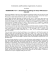
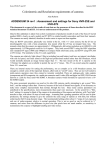
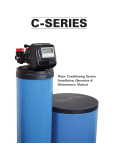
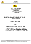
1
Brine Valve PN 3020511
Installation Manual
• Unique mechanical structure developed according to
scientific principles providing the best reliability.
• Highly expandable interface with replacement
fittings, to coordinate different uses of the control
valve.
• Adjustments are designed for ease of use and fast setup.
• Flow control is regulated by the body. Brine valve is
suitable for most water conditioning systems.
Specifications
Dimensions:
32" high unit:
3.2" L x 2.8" W x 27.38" H
(80 mm x 71 mm x 695 mm)
Rated Pressure:
20 - 120 psi (0.14 - 0.83 MPa)
Temperature Range:
34 - 140°F (1 - 60°C)
Used Media:
Clean municipal water or
brine
Max. Refill Water FLow:
1.2 GPM (4.5 L/m)
Max. Brine Flow:
1.0 GPM (3.7 L/m)
Materials:
Thank you for choosing the GE Safety Brine Valve. For a
complete water conditioner system, a brine valve is
indispensable for system protection and regeneration, as
well as ensuring the best water conditions.
The innovative design of the Brine Valve provides safe and
reliable performance, and is suitable for household and
commercial conditioner systems. This manual will help
you better understand the structure and properties of the
valve and will guide you through the installation.
We urge you to read this manual carefully and refer to it
any time a malfunction occurs. The Troubleshooting Table
highlights minor problems that you can correct yourself.
Main Valve:
ABS & PE
Seal:
Chlorine/Chloramines
resistant silicone rubber
Regenerant Tube Connection
The brine valve is compatible with a 3.5" (90 mm) GE brine
well, see Figure 1. The regenerant tube links the control
valve and the brine valve. Place one end of the right angle
elbow through the hole of the brine well. Slide the nut,
retaining sleeve and plastic gripper over the regenerant
tube. Insert the inner tube support and connect the
regenerant tube to the elbow. Finally, connect the other
end of the regenerant tube to the control valve.
Overview
The brine valve is suitable for household use. For a water
conditioner system, the brine valve has two principal
functions:
Air Check function - During system regeneration or a slow
rinse period, the brine valve prevents air from being pulled
into the resin tank, thereby ensuring the system’s
performance.
Refill Protection - “over-refill” may occur if the control
valve was set incorrectly or a system failure occurs. If this
happens, the brine valve is a protective device against
overfilling the brine tank.
Product Features
• Positive automatic opening and closing of the valve by
using vacuum or pressure.
Figure 1
Brine Valve PN 3020511
Brine Well Installation
Operation
1. The brine well should be vertically installed in the
regenerant tank.
The brine valve will work with the control valve to
automatically control the water level in the brine tank.
2. All connections should be manually tightened to
ensure a solid connection. DO NOT over tighten plastic
parts with a wrench, or you might damage plastic
components.
Another unique feature of the brine valve is the ability to
adjust the top support. The top bracket can be moved up
or down by loosening the lock nut. Hand tighten the
locknut.
3. Set the postion of the brine valve float. The float
should be positioned 0.8" - 2" (20 - 50 mm) above the
brine surface level or as required for application.
Regenerant Tube
CAUTION: DO NOT use petroleum based lubricants such as
vaseline, oils, or hydrocarbon based lubricants. Use only
100% silicone lubricant.
Base Plug
Valve Base
Figure 2
Disassembly
Assembly
Adjust Bracket
1/2” Lock Nut
Plastic Tube
Regenerant Tube - 3/8"
Figure 3
2
Arrow Direction to Tighten
Brine Valve PN 3020511
Troubleshooting
Problem
No water refill into the
salt tank
Possible Cause
Solutions
Brine valve not operating
Check that the brine valve is vertical and
moving freely.
Water flow is greater than 1.2 gpm
(4.5 L/m). Replace the refill control
washer with a smaller inside diameter
washer.
Check to see if there is too much air in
the resin tank.
Excessive refill
Obstruction in regenerant tube or valve
Inspect pipline, remove any debris.
Damaged brine valve
Replace brine valve.
Seal leak or failure
Check for debris on seal.
Replace the seal.
System uses less brine
than the regnerate
setting
The float does not close off incoming water
Float is restricted by the bracket. Raise
top bracket to allow more space for float
movement.
Damaged brine valve
Replace brine valve.
Air leak
Inspect pipeline and repair leaks.
Regenerant tube is too long
Be sure the length is less than 6.6 ft (2 m).
Brine valve is set incorrectly
Check and adjust floater to appropriate
height.
Be sure the refill controller is an
appropriate size.
The check ball was pulled at wrong time
3
Remove the check ball enclosure.
Brine Valve PN 3020511
Parts
9
10
11
No.
Description
No.
Description
1
Threaded connector
13
1/2-inch Lock nut
2
O-Ring, 22 x 1.8
14
3/8-inch Elbow
3
Regenerant tube
15
Pole base
4
Air check seal
16
Check ball
5
Float
17
Plastic pole
6
Rubber stop
18
Inner air check seal
7
Valve base
19
Inner connector
8
Base plug
20
Inner check ball enclosure
9
3/8-inch Retainer sleeve
21
Inner tube support
10
3/8-inch Plastic gripper
22
Fastener ring
11
3/8-inch Nut
23
Inner check seal retainer
12
Support bracket
© Copyright 2007 GE Water & Process Technologies
P/N 3020577 Rev C