1
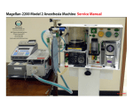
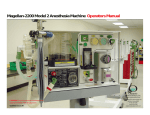
Magellan 2200, Model-3 Anesthesia Machine
Operator and Service Manual
CAUTION:
Federal Law Restricts this device to be
used by or on the order of a physician.
Key Service Contact Numbers
Phone: 913 874 2000
Fax: 913 874 2005
E-mail: [email protected]
02.17.08
2
Magellan 2200 Model-3 Anesthesia Machine
Operator and Service Manual
Table of Contents
Page
General Description
Definition of Statements
General Warnings
3
Machine Specifications
4
Functional and Operational Procedures
Assembly of Components
6
Pre-Use Checklist
9
FUNCTIONAL Operation of Controls and
Accessories
10
Post-Use Checklist
11
Cleaning and Disinfection
12
PROBLEM SOLVING GUIDE
13
CYLINDER GAS TABLE
13
Exploded View Diagrams
18
SERVICE MANUAL
WARRaNTY
20-25
27
3
General Description
The Magellan-2200, Model-3 Anesthesia Machine is
compact, robust and flexible, easy to transport and is a
simplified version of the Magellan-2200, Model-1
Anesthesia Machine that was originally designed for the
military. The Magellan-2200, Model-3 is designed to be
used when a mechanical ventilator is not needed and may
be used by mobile surgical teams, surgical specialty
hospitals, office-based anesthesia , hospitals, specialty
clinics of all descriptions and veterinary medicine.
The Magellan-2200, Model-3 may be mounted on its
custom-made carrying case, a mobile trolley or cart as
well as on a tabletop as the operator prefers.
FACTORY QUALITY ASSURANCE TESTING
Each Magellan-2200, Model-3 is tested several times during
the manufacturing process. Final testing and calibration of
components and the completed machine are recorded and
a final functional test certificate is included in the shipment
from the factory.
DEFINITION OF STATEMENTS
The following terminology and statements are important
for the operator to understand before proceeding with the
manual or operation of the Magellan-2200, Model-3:
WARNINGS: Indicate a possibility of injury to the operator
or others.
CAUTIONS: Indicate a possibility of damage to the
equipment.
NOTES: Indicate points of interest for proper operation of
the equipment.
4
SPECIFICATIONS
Dimensions:
Height
Width
Depth
14.5-inches
12-inches
8-inches
Weight:
Free Standing
Shipping Weight
29 lbs. fully equipped
40 lbs
Machine Materials:
aluminum, brass and plastic
Carrying Case Materials:
Plastic, military grade
Operating Temperature Range:
35 degrees F to
110 degrees F
Recommended Gas Supply Sources:
O2 Main and Cylinders
35 psi to 70 psi (50 psi is optimal)
O2 Concentrators
3-10 psi 5 psi is optimal)
Air Main, Cylinders and/or
35 psi to 70 psi (50 psi is optimal)
Air Compressors
Flowmeter Fresh Gas Flow
1 lpm to 20 lpm each flowmeter (20 lpm total)
Oxygen Flush Valve
Recessed, self-closing, push-button, color coded and labeled, provides 45-55 lpm constant flow while push-button is depressed
CO2 Absorber King Systems KAB-9 (re-fillable)
CO2 Absorber Canister Capacity 400 grams soda lime
Directional Valves
Built in the CO2 Absorber
CO2 Absorber Mounting Bracket Plastic, secured with knob to main frame of machine
Pressure Relief Valve and Waste-Gas Scavenging Scavenging Port
Attached to Bag/Gauge/PRV Arm
Common Gas Outlet
Quick-Connect, Size Indexed
Tubing Circuit
King SystemsF-360-61 or any standard anesthesia circle
Gas Pressure Hoses
DISS and Thread indexed, female connectors at both ends
Gas Inlet Manifold
DISS, Thread indexed male connectors with one way valves with separate filters
and filter spacers
continued on next page ...
5
Gas Inlet Pressure Regulators:
Main Supply Cylinder
Safety back-up Cylinder
DISS and Thread indexed for Oxygen and Air
Pin-Indexed, Yoke-mounted for “D” and “E” cylinders
Oxygen and Air Supply Gauges
0-3000 psi range, color-coded and clearly labeled
Oxygen Supply Alarm
Pneumatically actuated when supply pressure falls below 35 psi (mains)
1 psi (concentrator)
Alarm Power Source
9-volt battery located in body of alarm container
Air and Oxygen Flowmeters
Calibrated and scaled 0-10 lpm, color-coded, O2 flowmeter has fluted knob
for easy identification by touch
Oxygen Analyzer/Monitor
Maxtec OM-25-ME (or equivalent) galvanic cell sensor, sensor-life expectancy of 2 years under normal conditions
Oxygen Analyzer Power Source
2 each AA batteries, life expectancy approx 3000 use-hours
Auxiliary O2 Flow Selector
Scaled 0-10 lpm in set increments, used for pre/post anesthesia oxygen
administration with nasal cannula/mask
Vaporizer
Penlon Sigma Delta series, bolt (cage) mounted
Patient Pressure Gauge
Mounted on front side of Bag/PRV/Scavenger Arm, + 60 cmH2O to -60 cmH2O
Waste Gas Scavenger
Positive and negative relief valves, 1 liter reservoir, may be used with or
without constant vacuum (passive)
Total Machine Gas Leakage
@30 cmH2O
@80 cmH2O
-0- ml/min
-0- ml/min
Internal System Compliance
@20 cmH2O
@40 cmH2O
1.1 ml/cmH2O
1.3 ml/cmH2O
Internal System Resistance
@1.0 L/sec gas flow
@0.5 L/sec gas flow 4.11 cmH2O
1.80 cmH2O
APL Valve Pressure Drop
@3.0 l/min gas flow
@30 l/min gas flow
0.12 cmH2O
1.03 cmH2O
Storage Temperature
Indoors
+ 160 degrees F
Outdoors
- 30 degrees F (Allow unit to warm to normal operating
room temperature for at least one hour)
6
FUNCTIONAL & OPERATIONAL PROCEDURES
Assembly of Components
Back of Machine:
1.) Pressure Reducing Regulators/High Pressure Hoses
A. Emergency Back Up Oxygen:
Attach yoke-type regulator to the “D” or “E” cylinder to be used for safety back-up.
D. Oxygen Concentrator in Lieu of Main O2 Source:
If an O2 Concentrator is to be used instead of cylinder or wall O2 sources, the tubing from the Concentrator should be attached to the adapter that is labeled ➐ “Oxygen Concentrator Inlet Only.”
B. Oxygen Hose:
➊ Attach one end of the 24-inch green high pressure hose to the ➋ outlet port of the pressure reducing regulator and the ➌ opposite end to the ➍ left-side
Oxygen Inlet Connector on the Gas Manifold.
E. Water Trap:
➑ Attach the Water Trap to the Air Inlet port on the Gas Manifold.
Caution: Do NOT attach the Water Trap to the outlet
port of either an Air Wall Outlet or Medical Grade Air
Compressor as water may condense en-route to the
anesthesia machine in the high pressure tubing and
cause possible malfunction of some of the components.
C. Oxygen Hose Main O2 Supply:
➑ Attach one end of the 15-foot green high pressure ➎ hose to the top left Oxygen Inlet Connector on the
➏ Gas Manifold and the opposite end to the outlet port of a pressure-reducing regulator attached to an Oxygen cylinder or Oxygen wall outlet. See lower right photo.
F.
Air Hose:
Attach one end of the 15-foot yellow Air High-Pressure Hose to the inlet port of the Water Trap. Attach the opposite end of the hose to the air compressor outlet port or to the medical grade air sources (wall or cylinder).
➎
➏
➑
7
Left Side of Machine
2.) Waste Gas Scavenger:
A. Attach the waste gas scavenger to the keyholes located to the right of the low pressure alarm box,
then attach the reservoir bag to the bottom port of
the scavenger.
B. Attach suction source tubing to the inlet port of the scavenger control knob port.
1.) Bag-PRV/Scavenger Arm
As this component is already attached to the support pole, loosen the holding knob and swing the Arm so that the Pressure Gauge is facing the operator as shown below; tighten the holding knob.
C. Attach blue scavenger tubing to the labeled outlet port of the PRV/Scavenger and the opposite end to
the inlet port at the top of the scavenger.
VACUUM MANIFOLD
2.)
CO2 Absorber Support Arm
Attach the CO2 Absorber Support Arm to the main body of the machine by inserting the two guide pins of the arm into the two holes provided, then, insert the knob screw from the back side of the main body and tighten securely.
Attach the CO2 Absorber to the Support Arm and ensure that the Common Gas Outlet Tubing is attached to the CO2 Absorber as shown in the photo below:
8
3.) Tubing, CO2 Absorber to Bag-PRV/Scavenger Arm
Attach the Green, color-coded 22mm tubing to the
bottom-right outlet port of the CO2 Absorber and the
opposing end to the inlet port (located on the bottom
of the arm) of the Bag-PRV/Scavenger Arm, as shown
in the photo below.
Right Side of Machine
Vaporizer Mounting/Replacing
In the event that the vaporizer needs to be installed or
removed, the following method should be utilized:
A. Installation:
1. Insert the back side of the vaporizer into the cavity;
attach the size-coded inlet connector to the left-side
inlet port of the vaporizer.
2. Insert the two threaded stems into the two holes
provided, then mount the metal spacer onto the two
threaded stems on the Back side of the frame and
secure it in place with the two threaded knobs.
3. Attach the second size-coded connector to the
outlet port of the vaporizer.
4. If desired for transport or other reasons, place the
white plastic keeper under the bottom front of the
vaporizer and secure by using the two threaded
stem knobs into the two holes provided.
❰ A. Mount analyzer bracket
❰ B. Install analyzer
❰ C. Install O2 sensor on inhalation side of CO2 absorber
9
PRE-USE CHECKLIST
Emergency Ventilation Equipment
1. Verify Backup Ventilation Equipment is Available and Functioning
High Pressure System
2. Check Oxygen Cylinder Supply
A. Open O2 cylinder and verify at least half full
(approx. 1000 psi)
B. Close cylinder
3. Check Central Pipeline Supplies
A. Check that hoses are connected and pipline gauges read approx. 50 psi.
Low Pressure System
4. Check Initial Status of Low Pressure System
A. Close flow control valves and turn vaporizer off.
B. Check fill level and tighten vaporizer filler cap.
5.
Perform Leak Check of Machine Low Pressure System
A. Verify that the machine flow control valves are OFF.
B. Attach “Suction Bulb” to Common Fresh Gas Outlet.
C. Squeeze bulb repeatedly until fully collapsed.
D. Verify bulb stays full collapsed for at least 5 seconds.
E. Open vaporizer and repeat “c” and “d” above.
F. Remove suction bulb and reconnect fresh gas hose.
6. Test Flowmeters
A. Adjust flow of oxygen and air through their full range, checking for smooth operation of floats and undamaged flowtubes.
Scavenging System
7. Adjust and Check Scavenging System
A. Ensure proper connections between the scavenging system and APL (pop-off) valve
B. Adjust wasted gas vacuum (if needed).
C. Fully open APL valve and occlude Y-piece.
D. With minimum O2 flow, allow scavenger reservoir to collapse completely and verify that system pressure gauge reades approx. zero.
E. With the O2 flush activated, allow the scavenger reservoir bag to distend fully and then verify that system pressure gauge reads below 10 CmH2O.
Breathing System
8. Calibrate Oxygen Monitor
A. Ensure monitor reads 21% in room air.
B. Verify low oxygen alarm is enabled and functioning.
C. Reinstall sensor in circuit and flush breathing system with oxygen.
D. Verify that monitor now reads greater than 90%.
9. Check Initial Status of Breathing System
A. Check that breathing circuit is complete, undamaged and unobstructed.
B. Check reservoir bag is properly attached and undamaged.
C. Verify that CO2 absorbent is adequate.
D. Install breathing circuit accessory equipment (e.g. humidifier) to be used during the case.
10.Perform Leak Check of the Breathing System
A. Set all gas flows to zero or (minimum).
B. Close APL (pop-off) valve and occlude Y-piece.
C. Pressure breathing system to about 30 CmH2O with O2 flush.
D. Ensure that pressure remains fixed for at least
10 seconds.
E. Open APL (pop-off) valve and ensure that pres
sure decreases.
F. Close APL (pop-off) valve , attach an artificial lung
to the Y-piece and partially fill the reservoir bag, then manually compress the reservoir bag
and ensure that the one way valves and assure
inflation and deflation of artificial lung and
appropriate feel of system resistance and
compliance.
G. Remove the artificial lung from the Y-piece.
Monitors
11.Check, Calibrate and/or Set Alarm Limits of all Monitors
A. Oxygen Monitor
B. Physiologic Monitor
Final Position
12. Check Final Status of Machine
A.Vaporizer off.
B.APL valve open.
C.All flowmeters to zero.
D.Patient suction level adequate.
E. Breathing system ready to use.
10
FUNCTIONAL OPERATION OF CONTROLS AND
ACCESSORIES
With the Pre-Use Checklist completed, the Magellan
Model-3 is ready to use. It is imperative that the operator
understands how to utilize the controls of the machine
properly and the following information will be helpful:
the Inspiratory side of the patient tubing circuit.
One-way valves prevent the Oxygen Flush Gas from entering the vaporizer or being mixed with mixed gases from the flowmeters.
5.Flowmeters: The Oxygen and Air flowmeters are
operated by turning the individual control knobs
clock-wise for increased flow and counter-clockwise for
decreased flow.
NOTE: Titration of FIO2 is managed by using both
flowmeters and adjusting them until the desired FIO@ is
observed on the Oxygen Monitor display screen.
6.Common Gas Outlet: Provides a channel for all low flow
gas and vapor to flow to the inspiratory side of the CO2 Absorber, the reservoir bag and then on to the patient and rest of the circle system.
7.O2 power toggle selector for main O2 or concentrator
to power flowmeters.
8.Jackson-Reese/Mapelson-D Adapter: The adapter is
placed into the Common Gas Outlet and the selected bag-gas system is attached.
Gas Source Attachment
1. Attach the primary O2 source gas high pressure hose to either of the O2 DISS inlet adapters.
2. If the operator desires to use an Oxygen Concentrator as
an O2 source, attach the tubing from the concentrator to
either the qadapter labeled “O2 Concentrater”.
NOTE: When using an O2 concentrator as the primary O2
source, the maximum O2 concentration may not rise above
95%. Adjust the O2 Monitor low O2 % alarm accordingly.
1. Auxiliary O2 Flow Selector: Designed to allow the
operator to supply oxygen to a patient pre and post-op, with masks or cannula’s featuring small bore tubing. The selector knob will provide oxygen flow at 2,4,6,10 and
15 liters per minute.
NOTE: When not in use, the selector control should be in
the “O” position in order to not waste oxygen sources.
2.Oxygen Pressure Gauge: Indicates the source pressure
of Oxygen for all Oxygen-related components of the system.
3.Air Pressure Gauge: Indicates the source pressure of Air
for all Air-related components of the system.
4.Flush Button: Press the button inwards to activate
100% Oxygen through the system.
When activated, the oxygen gas flows for the flush
button to the Common Gas Outlet and then directly to 9. Vaporizer: The Penlon Delta Sigma vaporizers are
generally used with the Magellan anesthesia machines.
Please refer to the Penlon vaporizer Operator’s Manual for
instructions on use – depending on whether the vaporizer
is key-filled, pour-filled or Abbott adaptor-filled.
WARNING: Tilting the vaporizer past 45 degrees with liquid
in the chamber can result in patient imjury or death.. IF
tilted past 45 degree, empty the chamber, fully open the
percent control, then open the Oxygen flowmeter to 5 lpm
for 10 minutes. Operation may then resume normally.
11
12
Post-Use Checklist
1. Turn off all inlet gas pipeline and cylinder sources.
2. Turn off the vaporizer and completely empty the
fluid chamber.
3. Remove all patient-contact tubing and fittings.
4. Turn off Air and/or Oxygen and physiologic monitors.
5. Turn off back-up Oxygen cylinder.
13
CLEANING AND DISINFECTION
The Magellan-2200, Model-3 may have the entire exterior
of the device cleaned with a mild solution of soap and
water and thoroughly dried off.
Disinfection of the outer contents of the entire device may
be accomplished with a mild hospital-grade disinfectant
solution, such as CaviCide. Follow manufacturer’s
directions.
Minor Maintenance Recommendations
NOTE: For all testing procedures, pre- and postmaintenance, utilize the Pre-Use Checklist (beginning
on page 11 of this manual) to ensure that all components
are properly working.
Semi-Annual Maintenance
Back side of unit:
Gas Manifold
1. Remove the holding screw for the two oxygen and one
air retainers surrounding/securing the oxygen and air
DISS inlet adapters.
2. Remove the round spacer units from the manifold.
3. Remove the cone-shaped filter from the manifold.
4. Replace the filter, followed by the spacer then screw
in the DISS adapter.
5. Place the air and oxygen adapter retainers and tighten
the screws.
Gas Hoses and Regulators
6. Inspect the two oxygen and one air high pressure
hoses for wear and kinking.
7. Inspect the pin-indexed oxygen pressure reducing
regulator, ensuring that the pins are straight.
Front Side of Unit
9. Inspect the vaporizer, unlock and rotate the agent
concentration control selector, ensuring that it moves
freely and locks into the closed position when closed.
10. Inspect vaporizer retainer, ensuring that the holding
screws are securely in place.
11. Inspect the mounting adapters for the auxiliary
oxygen selector, oxygen and air pressure gauges, flush
button, flowmeters and gas pressure selector switch,
ensuring holding nuts are tight.
12. Inspect the soda lime absorber and mounting bracket
for undue wear.
13. Inspect the pressure gauge/scavenger/pressure relief
valve assembly for undue wear.
14. Inspect the reservoir bag and replace if needed.
Perform the Pre-Use Checklist and ensure that all
components are working properly, post-maintenance.
14
PROBLEM SOLVING GUIDE
15
GAS FLOW DIAGRAMS
16
17
18
19
20
21
Table of Contents
Page
purpose OF DOCUMENT
21
GENERAL POLICY
21
EQUIPMENT AND TOOLS FOR SERVICE
21
ANNUAL MAINTENANCE, PARTS AND TESTING
22
ROUTINE TESTING
23
CLEANING AND DISINFECTION
24
MINOR MAINTENANCE RECOMMENDATIONS
24
GENERAL WARNINGS
25
WARRENTY
26
LIMITATIONS OF LIABILITIES
27
22
PURPOSE OF DOCUMENT
This Service Manual provides the reader with important
information concerning the general service, maintenance
and general repair of the Magellan-2200, Model 1
Anesthesia Machine.
This manual will allow for the service of the Magellan-2200,
Model 1Anesthesia Machine and its accessories. This
machine may be fully serviced outside of the factory and
the reader may contact the factory at any time for
assistance.
General Policy Statement
The scope of this manual covers general maintenance,
calibration of controls, disinfecting procedures and
replacement of certain components at the intervals
indicated within this document..
Equipment Needed for Bench Testing
1. Operators Manual
6.Rubber Test Lung or Any One Liter Rubber Test Lung
or One Liter Gas Reservoir Bag: Used to simulate patient
delivered gas volumes if mechanical Test Lung is not
available.
2. Pre-Use Check List: Contained in this manual, the
Operators Manual and Separate Laminated Card
7.Carbon Dioxide Absorber: King Systems KAB-9 unit,
either full of absorbent or empty.
3. Regulated, Pressurized Gas Sources: Wall outlets for oxygen and air, gas cylinders for oxygen and air, each
with appropriate pressure-reducing regulators, portable medical grade air compressor and oxygen concentrator.
8.Patient Tubing Circuit: Any approved Patient Tubing
Circuit for Anesthesia may be utilized.
4.
Mechanical or Electrical-Mechanical Test Lung: The
factory utilizes the Bio-Med VT-2A Test Lung, however, other brands of such devices may be used for bench
testing.
5. Hand-Operated Spirometer: May be used for gas volume calibration if other mechanical test lungs are not available.
9.Monitoring Device for Anesthetic Agent: Either a
specific vaporized agent testing device such as a Bickford
Anesthesia Agent Tester, Model-3, or an anesthesia monitor
capable of measuring vaporized agent may be used.
10. Tools: The Magellan-2200, Model 3 Anesthesia
Machine was designed to be serviced with the following
common tools:
A.1/16-inch Allen’s Wrench-used with O2 flowmeter
control knob and the three ventilator control knobs.
B.Screwdriver, regular slotted head.
C.Small, adjustable crescent wrench, or:
1.1/2-inch open head wrench
2.7/16-inch open head wrench
3.regular pliers
D.1-inch sealing tape roll
E. Tube of Krytox (or other oxygen compliant) lubricant
F. Water-based leak testing solution
23
ANNUAL MAINTENANCE, PARTS NEEDED AND
TESTING
Recommended Inspection/Replacement of Certain
Components
A.Annually: The following procedures should be used to ensure proper operation of the machine, at least once per year or at any other interval that the Biomedical Technician deems necessary.
B. Parts Needed: The following parts will be needed for Annual Service
• Inlet Filters (2 each) P/N 11.3
1. Changing the Gas Manifold Inlet Filters:
Oxygen (DISS) Inlet Connectors:
(the first one is located next to the Air Connector, the
second one is located on the left-hand side of the Gas
Manifold and the procedure is identical for both Oxygen
DISS Inlet connectors.)
A. Using a crescent wrench, unscrew the DISS Oxygen.
B. Remove the filter spacer (aluminum ring) then remove the cone-shaped filter.
C. Inspect the filter for debris. If debris is found, remove it.
D. Install the filter back into the Gas Manifold (with original or new filter).
E. Install the filter spacer (aluminum ring).
Air (DISS) Inlet Connector:
A.Using a crescent wrench, unscrew the DISS Air inlet connector and remove.
B. Remove the filter spacer (aluminum ring) then remove the cone-shaped filter.
C. Inspect the filter for debris. If debris is found, remove it.
D.Install the filter back into the Gas Manifold (with original
or new filter) with the small end first.
E. Install the filter spacer (aluminum ring).
F. Pull open the one-way valve (located on the end of the threaded portion of the DISS adapter), and apply some Krytox (or, equivalent) lubricant.
G.Re-tape the DISS Air connector, threaded portion, with sealant tape.
H.Re-install the DISS Air connector, screwing it closed, snugly, with the crescent wrench.
F. Pull open the one way valve (located on the end of the threaded portion of the DISS adapter) and apply some Krytox (or, equivalent) lubricant.
G. Re-tape the DISS Oxygen connector, threaded portion, with sealant tape.
H. Re-install the DISS Oxygen Connector(s), screwing it closed, snugly, with the crescent wrench.
2.Mandatory Replacement of Gas Manifold High Pressure Color-Coded Tubing
Every five years or, at any necessary time, each of the 10
color-coded tubes that attaches to/from the Gas Manifold
should be replaced using the following procedure:
NOTE: The end of the color-coded tubing must be squarely cut; angled ends may not seat properly.
A. Green (oxygen) and Yellow (Air) Tubing: The connectors from the Gas Manifold to each of the following components are of the “push-to-insert-and-lock” type.
B. To dismount, push in on the outer ring and pull the tubing out.
C. To re-insert, push the end of the green tubing into the receptacle and then use a “pulling” action to lock the tube in place.
24
Yellow Tubing Positions From Gas Manifold to:
A. Air Pressure Gauge
B. Air Position on the Ventilator Gas Selector Toggle Switch
C. Air Flowmeter
II.ROUTINE FUNCTIONAL TEST : The functional test may
be done at annual intervals or at any time that internal
components have been replaced.
NOTE: The Routine and Annual Functional Test may be
carried out at any interval. This test will indicate any
malfunction of the machine or its components and the
Operator or Biomedical Technician will be able to rectify
any component that is not functioning properly.
Test Procedure:
1. Assemble and install all components needed for routine clinical use of the machine as outlined in the Operators Manual, or the Laminated Set-Up Card.
2. Perform the Pre-Use Checklist and Laminated Set-Up Card (with photos) in sequence. This Checklist is contained in the Operators Manual; the separate
Pre-Use Checklist laminated card and Set-Up Card are provided with each machine.
Green Tubing Positions From Gas Manifold to:
A. Auxiliary O2 Flow Selector
B. O2 Pressure Gauge
C. O2 Flush Valve
D. O2 Flowmeter
E. O2 Position on Ventilator Gas Selector Toggle Switch
F. O2 Concentrator/High Pressure O2 Selector Toggle Switch
G. O2 Low Pressure Alarm
H. O2 Very Low Pressure / O2 Concentrator Pressure Alarm
NOTE: If the machine passes the Pre-Use Checklist with
zero problems, proceed to the Calibration Guide in the next
section.
CAUTION: If the machine does not pass the Pre-Use Checklist, correct the problem(s) encountered, then proceed with
the Calibration Guide. The Problem Solving Guide on page
13 of this Manual will assist the Operator in resolving
possible common problem situations.
NOTE: If the machine passes the Pre-Use Checklist with
zero problems, proceed to the Calibration Guide in the
next section.
CAUTION: If the machine does not pass the Pre-Use Checklist, correct the problem(s) encountered, then proceed with
the Calibration Guide. The Problem Solving Guide on page
13 can assist the Operator in resolving possible common
problems.
25
CLEANING AND DISINFECTION
MINOR MAINTENANCE RECOMMENDATIONS
Cleaning
The Magellan-2200, Model 3 may have the exterior of the
device and its external components, cleaned with a mild
solution of soap and water, then thoroughly dried off.
Purpose
To ensure the Magellan-2200, Model 3 Anesthesia Machine
is in proper operating condition.
Disinfection
The Magellan-2200 may have the entire exterior of the
device and its exterior components, disinfected with a
mild, hospital grade disinfectant solution such as CaviCide.
Follow the disinfectant manufacturers directions for use.
Steam Sterilization
The following components may be autoclaved at a
temperature of 121 degrees C for 15 minutes:
1. Tubing and connectors from the common gas outlet to
the absorber inlet port.
2. Tubing and connectors from the air and oxygen
flowmeters to the vaporizer port.
3. Tubing and connectors from the outlet port of the
vaporizer to the common gas outlet.
4. Tubing and connector for the scavenger system.
5.Oxygen sensor “tee” mount.
6. Bag/Vent switch assembly and support arm.
Vaporizer
1.The process of filling and emptying the vaporizer
with agent will clean the internal passageways of the
vaporizer filler block satisfactorily.
2.The exterior of the vaporizer should be kept clean and
dust free with a dry cloth, or, if necessary, use proprietary
cold sterilized wipes or cloths and dry thoroughly.
CO2 Absorber Canister (refillable version)
1.The King Systems KAB-9 refillable absorber may be
autoclaved 40 times then should be replaced.
Scope of Recommendation
These recommendations are for routine maintenance.
Annual or other maintenance procedures are contained
in the Magellan-2200, Model 3 Service Manual.
Recommendations
1. Perform a Pre-Use Check according to the Pre-Use
Checklist.
2. Check all monitoring devices according to the
manufacturers recommendations.
3. Ensure that the Oxygen sensor can be calibrated
properly. If the sensor does not calibrate, replace.
Tools Needed for All Maintenance
1. 1-16-inch Allen Wrench
2. Screwdriver, regular head
3. Small, adjustable wrench
26
GENERAL WARNINGS
1. Patients requiring life-support equipment should be under constant surveillance of competent medical practitioners. There is always the possibility of machine and alarm failure and some malfunctions require immediate, corrective action.
2. Vaporizer-Tilting the vaporizer past 45 degrees with liquid agent in the chamber can result in patient injury or death. If tilted past 45 degrees, empty the chamber, fully open the percent control, then flush the vaporizer with Oxygen from the Oxygen flow-meter set to 5 lpm for 10 minutes.
27
WARRANTY
LIMITATIONS OF LIABILITIES
The products of Oceanic Medical Products, Inc. (OMPI
herein) are warranted to be free from defects in materials
and workmanship and to meet the published specifications
for a period of five (5) years from date of delivery to the
original customer.
This warranty does not cover normal maintenance such as
cleaning, adjustment or lubrication and updating of
equipment or parts. This warranty shall be void and shall
not apply if the equipment is used with accessories or
parts not manufactured by OMPI or authorized for use in
writing by OMPI, or if the equipment is not maintained in
accordance with a prescribed schedue of maintenance.
The warranty stated above shall extend for a period of five
years from date of delivery, effective November 15, 2000.
Te foregoing is in lieu of any other warranty, expressed or
implied, including, without limitation, warranty of
merchantability, except as to title, and can be amended
only in writing by a duly authorized representative of OMPI.
The liability of OMPI under this warranty is limited to
replacing, repairing or issuing credit, at the discretion of
OMPI, for the parts that become defective or fail to meet
published specifications during the warrant period; OMPI
will not be liable under this warranty unless (a) OMPI is
promptly notified in writing by Buyer upon discovery of
defects or failure to meet specifications; (b) the defective
unit or part is returned to OMPI, with transportation
charges prepaid by Buyer; (c) the defective unit or part is
received by OMPI for adjustment no later than four weeks
following the last day of the warranty period; and (d)
OMPI examination of such unit or part shall disclose, to its
satisfaction, that such defects or failures have not been
caused by misuse, neglect, improper installation,
unauthorized repair or alteration, or accident.
Any authorization by OMPI for repair or alteration by the
buyer must be in writing to prevent voiding warranty. In
no event shall OMPI be liable to buyer for loss of profits,
loss of use, consequential damage or damages of any
kind based upon a claim for breach of warranty, other
than the purchase price of any defective product covered
hereunder. OMPI warranties hereinabove set forth shall not
be enlarged, diminished or affected by, and no obligation
or liability shall arise or grow out of, the rendering of
technical advice or service by OMPI or its agents in
connection with Buyers order of the products furnished
hereunder.
Returned Goods Policy
All returns must be authorized by OMPI prior to shipping.
Returned goods are subject to a 20 percent restocking fee.
Contact OMPI Customer Service with your request for an
authorization number.of the products furnished hereunder.
28
8005 Shannon Industrial Park Lane
Atchison, Kansas 66002
913 874 2000 913 874 2005 FAX
e-mail: [email protected]
02.17.08