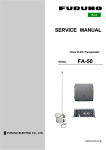
1
IMPORTANT NOTICES
General
• This manual has been authored with simplified grammar, to meet the needs of international
users.
• The operator of this equipment must read and follow the descriptions in this manual. Wrong
operation or maintenance can cancel the warranty or cause injury.
• Do not copy any part of this manual without written permission from FURUNO.
• If this manual is lost or worn, contact your dealer about replacement.
• The contents of this manual and equipment specifications can change without notice.
• The example screens (or illustrations) shown in this manual can be different from the screens
you see on your display. The screens you see depend on your system configuration and
equipment settings.
• Save this manual for future reference.
• Any modification of the equipment (including software) by persons not authorized by FURUNO
will cancel the warranty.
• All brand and product names are trademarks, registered trademarks or service marks of their
respective holders.
How to discard this product
Discard this product according to local regulations for the disposal of industrial waste. For disposal
in the USA, see the homepage of the Electronics Industries Alliance (http://www.eiae.org/) for the
correct method of disposal.
How to discard a used battery
Some FURUNO products have a battery(ies). To see if your product has a battery(ies), see the
chapter on Maintenance. Follow the instructions below if a battery(ies) is used.
In the European Union
The crossed-out trash can symbol indicates that all types of batteries
must not be discarded in standard trash, or at a trash site. Take the
used batteries to a battery collection site according to your national
legislation and the Batteries Directive 2006/66/EU.
Cd
In the USA
The Mobius loop symbol (three chasing arrows) indicates that Ni-Cd
and lead-acid rechargeable batteries must be recycled. Take the used
batteries to a battery collection site according to local laws.
In the other countries
Ni-Cd
Pb
There are no international standards for the battery recycle symbol. The number of symbols can
increase when the other countries make their own recycle symbols in the future.
i
SAFETY INSTRUCTIONS
Read these safety instructions before you operate the equipment.
WARNING
Indicates a condition that can cause death or serious
injury if not avoided.
CAUTION
Indicates a condition that can cause minor or moderate
injury if not avoided.
Warning, Caution
Mandatory Action
Prohibitive Action
Safety Instructions for the Operator
WARNING
WARNING
Immediately turn off the power at the
switchboard if water leaks into the
equipment or something is dropped
into the equipment.
Use the proper fuse.
Fuse rating is shown on the power
cable. Use of a wrong fuse can result in
damage to the equipment.
Continued use of the equipment can cause
fire or electrical shock. Contact a FURUNO
agent for service.
Do not place any object near the
exhaust or intake vent.
Immediately turn off the power at the
switchboard if the equipment is emitting
smoke or fire.
Fire may result.
Continued use of the equipment can cause
fire or electrical shock. Contact a FURUNO
agent for service.
CAUTION
Do not disassemble or modify the
equipment.
Do not connect/disconnect the signal
cable while turning the power on.
Fire, electrical shock or serious injury
can result.
The unit may be damaged.
Turn off the power immediately
if you feel the equipment is behaving
abnormally.
Handle the LCD monitor with care.
Turn off the power at the switchboard if
the equipment becomes abnormally warm
or is emitting odd noises. Contact a
FURUNO dealer or agent for advice.
The face of the LCD monitor is made
of glass. Injury may result if the
glass breaks.
ii
SAFETY INSTRUCTIONS
Safety Instructions for the Installer
WARNING
CAUTION
Turn off the power at the switchboard
before beginning the installation.
Observe the following compass safe
distances to prevent interference to a
magnetic compass:
Fire or electrical shock can result if the
power is left on.
Do not install the equipment where it
may get wet from rain or water splash.
MU-150HD
Water in the equipment can result in fire,
electrical shock or damage to the
equipment.
Standard
compass
Steering
compass
0.65 m
0.45 m
When lifting the display unit, hold it
together with the hard cover.
Grasping by the hard cover alone may
allow the display unit to fall, resulting in
possible bodily injury or damage to the
equipment.
About the TFT LCD
The TFT LCD is constructed using the latest LCD techniques, and displays
99.99% of its pixels. The remaining 0.01% of the pixels may drop out or
blink, however this is not an indication of malfunction.
iii
TABLE OF CONTENTS
Note: This manual contains both English and Japanese instructions. The Installation
Materials, Outline Drawings, and Interconnection Diagram are located at the back of this
manual.
FOREWORD ....................................................................................................................v
SYSTEM CONFIGURATION ..........................................................................................vi
EQUIPMENT LISTS .......................................................................................................vii
1.
MOUNTING, WIRING................................................................................................1
1.1
1.2
1.3
1.4
1.5
1.6
1.7
2.
Preparation.................................................................................................................... 1
Flush Mounting, Fixed at Rear ...................................................................................... 3
Flush Mounting, Fixed at Front ..................................................................................... 6
Flush Mounting, Fixed at Rear, with hood..................................................................... 8
Desktop Mounting ....................................................................................................... 10
Flush Mounting a Series Side by Side ........................................................................ 13
Wiring .......................................................................................................................... 14
ADJUSTMENTS......................................................................................................16
2.1 RGB/DVI Setting ......................................................................................................... 16
2.2 Video Composite Signal Setting.................................................................................. 18
2.3 The Menu Window Setting .......................................................................................... 19
2.3.1 How to adjust the menu window .......................................................................... 19
2.3.2 How to change the signal name .......................................................................... 20
3.
OPERATION ...........................................................................................................21
3.1 Controls....................................................................................................................... 21
3.2 How to Turn the Power On/Off.................................................................................... 22
3.2.1 Turn on/off the power........................................................................................... 22
3.2.2 Lock the operation ............................................................................................... 22
3.3 How to Adjust the Display Brilliance............................................................................ 22
3.4 How to Select the Source for Main Picture ................................................................. 23
3.5 How to Select the Source for the PIP Window............................................................ 23
3.6 SYSTEM Menu ........................................................................................................... 24
3.6.1 How to set the auto dimmer................................................................................. 24
3.6.2 How to adjust the brilliance from the external equipment .................................... 25
3.6.3 How to clear the memory..................................................................................... 25
4.
MAINTENANCE, TROUBLESHOOTING................................................................26
4.1 Maintenance................................................................................................................ 26
4.2 Troubleshooting .......................................................................................................... 27
SPECIFICATIONS .....................................................................................................SP-1
INSTALLATION MATERIALS ..................................................................................... A-1
OUTLINE DRAWINGS................................................................................................. D-1
INTERCONNECTION DIAGRAM ................................................................................ S-1
iv
FOREWORD
A Word to the Owner of the MU-150HD
FURUNO Electric Company thanks you for purchasing the MU-150HD 15” Marine Display. We are
confident you will discover why the FURUNO name has become synonymous with quality and reliability.
For over 60 years FURUNO Electric Company has enjoyed an enviable reputation for quality and
reliability throughout the world. This dedication to excellence is furthered by our extensive global
network of agents and dealers.
Your equipment is designed and constructed to meet the rigorous demands of the marine environment. However, no machine can perform its intended function unless properly installed and
maintained. Please carefully read and follow the operation, installation and maintenance procedures set forth in this manual.
We would appreciate feedback from you, the end-user, about whether we are achieving our purposes.
Thank you for considering and purchasing FURUNO.
Features
The main features of the MU-150HD are as shown below.
• Selectable screen from RGB (1 line), Digital (2 lines) or Composite (3 lines).
• Main or remote display for radars, video sounders, sonars, plotter. For the connectable equipments, see "Connectable equipment" on page vi.
• High resolution display of 1024 x 768 (XGA)
• Brightness of 1000 cd/m2 (maximum) and 0.3 cd/m2 or less (minimum) for comfortable viewing
day and night.
• Brilliance adjustment automatically with the light sensor.
• Picture-in-picture function
• Power on/off automatically through the DVI signal.
Program Number
Program Name
Main
Version
Date of Modification
1.xx
Feb. 2010
xx: minor change
v
SYSTEM CONFIGURATION
12-24 VDC
RGB
MODEL1824C/1833C/1943C,
FSV-30, FCV-30, FCV-1200L etc.
DVI
2 ports
MFD8/MFD12/MFDBB,
FAR-21X7 series etc.
VIDEO (NTSC/PAL)
3 ports
CCD camera,
DVD recorder, etc.
MARINE DISPLAY
MU-150HD
Environmental category
MU-150HD: Protected from the weather
Connectable equipment
Equipment
FCV-1200L/M
CH-250/S
CH-270
CH-300
CSH-5L/8L
FSV-24/S-BB
FSV-30/S-BB
FSV-84/L
FCV-30
CI-68/88
FR-1510MK-3
FR-21x5 series
FAR-21x7 series
FEA-2107
FEA-2807
FCR-21x7 series
FCR-28x7 series
MODEL1833C series (NAVnet)
MODEL1833C-BB series (NAVnet)
MODEL1824C series (NAVnet vx2)
MODEL1824C-BB series (NAVnet vx2)
MFD8 (NAVnet 3D)
MFD12 (NAVnet 3D)
MFDBB (NAVnet 3D)
Resolution
VGA
VGA
VGA
VGA
XGA
SXGA
SXGA
SXGA
SXGA
VGA
XGA
SXGA
SXGA
SXGA
SXGA
SXGA
SXGA
VGA
VGA
VGA
VGA
VGA
SVGA
SVGA
XGA
SXGA
Signal
Analog RGB, via IF-8000
Analog RGB, via IF-8000
Analog RGB, via IF-8000
Analog RGB, via IF-8000
Analog RGB
Analog RGB
Analog RGB
Analog RGB
Analog RGB
Analog RGB
Analog RGB, OP03-153 required
Analog RGB, OP03-162 required
DVI
DVI
DVI
DVI
DVI
Analog RGB, OP03-176 required
Analog RGB
Analog RGB, OP03-176 required
Analog RGB
DVI
DVI
DVI
Note 1: This equipment is used as a display for a Non-SOLAS radar or ECDIS.
Note 2: Landscape orientation only.
Note 3: When inputting SXGA, a circle may be displayed as an ellipse because the aspect ratio
differs. See "DISP MODE*" on page 17. Also, it may be difficult to read small characters.
vi
EQUIPMENT LISTS
Standard supply
Name
Type
Code No.
—
Qty
1
Remarks
Display Unit
MU-150HD
w/ Hard cover
Installation
Materials
CP26-01300
000-016-267
1 set • CP26-01302*
• Flush Mounting Plate Assy. (CP26-01301,
Code: 001-080-760) 2 pcs.
• Cable Assembly (MJ-A3SPF0017-050ZC,
Code: 000-157-995-10) 1 pc.
Accessories
FP26-00401
001-080-780
1 set LCD Cleaning Cloth (02-155-1082-1, Code:
100-332-651-10) 1 pc.
Spare Parts
SP26-00201
001-080-750
1 set • Fuse (FGBO-A 125V 5A PBF, Code: 000155-853-10) 3 pcs.
• Fuse (FGBO 125V 10A PBF, Code: 000155-826-10) 3 pcs.
*: See the Installation materials at the back of this manual.
Optional supply
Name
Type
Code No.
Qty
Remarks
3COX-2P-6C 5M
001-077-230-10 1
Cable length: 5 m (15 pin D-sub
connector at both ends)
3COX-2P-6C 10M
001-077-220-10 1
Cable length: 10 m (15 pin Dsub connector at both ends)
DVI-D/D
SINGLELINK5M
000-149-054-10 1
Cable length: 5 m
(with DVI-D connector at both
ends)
DVI-D/D
SINGLELINK10M
000-150-200-10 1
Cable length: 10 m
(with DVI-D connector at both
ends)
Bracket Assembly
(w/knobs)
OP26-2
000-016-268
1 set
Hood Assembly
OP26-3
001-080-840
1 set
Flush Mount Kit
OP26-4
001-080-850
1 set
Cable Assembly
vii
1.
MOUNTING, WIRING
1.1
Preparation
Mounting type
You can install the display unit as follows. See the outline drawing at the back of this manual for
mounting dimensions.
• Flush mounting, fixed at rear (standard)
• Flush mounting, fixed at front (option)
• Flush mounting, fixed at rear, with hood (option)
• Desktop mounting (option)
• Flush mounting a series side by side, fixed at rear
Note: The face of the LCD monitor is made of glass. Handle it with care.
Mounting location
When you choose a mounting location, remember the following points:
• Make sure the mounting location is strong enough to support the weight of the unit.
• Locate the unit away from direct sunlight. An LCD may black out if it is exposed to direct sunlight
for a long time.
• Select a location where the display can be easily viewed and the controls can be easily operated.
• Leave enough space around the unit for service and maintenance. See the outline drawing at
the back of this manual for minimum service clearance.
• Locate the unit away from areas subject to water splash and rain.
• Observe the compass safe distances (see page iii) to prevent interference to a magnetic compass.
How to remove/attach the hard cover
Before you install this display unit, remove the hard cover as follows.
CAUTION
When lifting the display unit, hold it
together with the hard cover.
Grasping by the hard cover alone may
allow the display unit to fall, resulting in
possible bodily injury or damage to the
equipment.
1
1. MOUNTING, WIRING
The upper edge of the hard cover
Pull forward the upper
edge by pressing here
with thumbs.
How to remove the hard cover
To attach the hard cover, follow the illustration in the figure below.
Cutout
Tab
Hard cover
Set the tabs on the top
of the hard cover to the
cutouts of the display
unit.
Push the tabs of the
bottom of the hard cover
strongly (2 places).
How to attach the hard cover
Cable running
Before you install the display unit, run all cables you use. See the interconnection diagram at the
back of this manual.
2
1. MOUNTING, WIRING
1.2
Flush Mounting, Fixed at Rear
This is the standard installation method.
1. Make a cutout in the mounting location with the “Flush mounting template” (included).
4-ø18(0.71”)
9 (0.35”)
9 (0.35”)
314±1 (12.36”)
364±1 (14.33”)
2. Attach the flush mounting sponges H15 and V15 in the order shown in the figure below.
Flush Mounting Sponge (H15)
for top and bottom
Flush Mounting Sponge (V15)
for right and left
3. Connect all cables at the back of the display unit. See section 1.7.
3
1. MOUNTING, WIRING
4. Set the display unit to the cutout.
Cutout
5. Screw the wing bolts and the wing nuts of the flush mount fixture so that the protector moves
to the mounting plate.
Wing Bolt
Wing Nut
Mounting Plate
Protector
Flush Mount Fixture 15
Set to the fixture.
4
1. MOUNTING, WIRING
6. Fasten the flush mount fixture 15 to the right and left sides of the rear of the display unit with
the washer head screws (6 places).
Washer Head Screw
Flush Mount Fixture 15
7. Fasten the wing bolts, in the order of the number shown in the figure below so that the protectors touch the mounting panel.
㽷
㽳
㽵
8. Fasten the wing bolts tightly, in the order shown in step 7.
9. Fasten the wing nuts tightly.
Wing Bolt
Wing Nut
Mounting Plate
Protector
Mounting Panel
5
1. MOUNTING, WIRING
1.3
Flush Mounting, Fixed at Front
If you do not have the enough space to fix the display unit from the rear, you can fix it from the
front with the Flush mount kit OP26-4 (option).
Flush Mount Kit OP26-4 (Code: 001-080-850)
Name
Type
Code No.
Qty.
Flush Mounting Panel (15)
OP26-4-1
001-080-960-00
1
Washer Head Screw
M4x10
000-163-836-10
8
Self Tapping Screw
5x20
000-162-609-10
4
Flush Mounting Template
C42-00909
000-172-636-10
1
1. Make a cutout in the mounting location with the flush mounting template (included).
370 (14.57”)
332±0.5 (13.07”)
9 (0.35”)
9 (0.35”)
320 (12.60”)
4-ø18 (0.71”)
Pilot hole
for mounting from the front
382±0.5 (15.04”)
2. Attach the flush mounting sponges H15 and V15 in the order shown in the figure below.
Flush Mounting Sponge (H15)
for top and bottom
Flush Mounting Sponge (V15)
for right and left
6
1. MOUNTING, WIRING
3. Attach the flush mounting panel to the display unit from the rear with the washer head screws
(8 places). Do not confuse the top and bottom of the panel and check that screw holes on the
panel and unit match.
Narrow
Flush Mounting Panel (15)
Wide
Washer Head Screw
4. Connect all cables at the back of the display unit. See section 1.7.
5. Set the display unit assembly prepared at the step 3 to the cutout for the mounting location.
6. Fix the display unit to the cutout with the self tapping screws (4 places).
Self Tapping Screw
7
1. MOUNTING, WIRING
1.4
Flush Mounting, Fixed at Rear, with hood
You can attach a hood when flush mounting the unit from the rear, using the hood assembly
OP26-3 (option).
Hood Assembly OP26-3 (Code: 001-080-840)
Name
Type
Code No.
Qty.
Hood (15) Assembly
OP26-3-1
001-080-950-00
1
F-Mount Hood Gasket 15
26-005-2305
100-351-710-10
1
Hood Gasket Bottom 15
26-005-2306
100-351-720-10
1
F-Mount Hood Gasket Side 15
26-005-2307
100-351-730-10
2
Hood Fixing Plate 15
26-005-2302
100-351-321-10
2
Knob M4
03-163-2303
100-343-602-10
4
Flat Head Screw
M3x8
000-172-167-10
6
Flush Mounting Template
C42-00908
000-172-635-10
1
1. Make a cutout in the mounting location with the flush mounting template (included).
4-ø18 (0.71”)
9 (0.35”)
9 (0.35”)
314±1 (12.36”)
368±1 (14.49”)
2. Fix the hood fixing plates to the right and left of the display unit with the flat head screws (6
places).
Flat Head Screw
Hood Fixing Plate 15
8
1. MOUNTING, WIRING
3. Attach the “F-Mount Hood Gasket 15” to the top brim, the “Hood Gasket Bottom 15” to the
bottom brim, and then attach the “F-Mount Hood Gasket Side 15” to the right and left sides of
the display unit from the rear side as shown the figure below.
F-Mount Hood Gasket 15
F-Mount Hood Gasket Side 15
Hood Gasket Bottom 15
4. Follow steps 3 to 9 in section 1.2 to fix the display unit to the mounting location.
5. Loosely fix the knobs (4 pcs.) to the hood fixing plate.
6. Slide the cutouts of the hood assembly to the knobs.
Knob (4 pcs.)
Hood (15) Assembly
Hood Fixing Plate 15
Cutout (4 places)
9
1. MOUNTING, WIRING
7. Press the top of the hood to fit the knobs in the cutouts.
Press
Press
8. Fix the hood assembly with the knobs tightly (4 places).
1.5
Desktop Mounting
You can fix the display unit to a desktop, using the bracket assembly OP26-2 (option).
Bracket assembly OP26-2 (Code: 000-016-268)
Name
Type
Code No.
Qty.
Mounting Bracket (15)
OP26-2-1
001-080-820-00
Bracket Support w/knobs
OP26-2-2
001-080-830-00
Self-Tapping Screw
5x20
000-162-608-10
4
Binding Head Screw
M4x10
000-172-165-10
9
10
1
1. MOUNTING, WIRING
1. Loosen the knobs of the bracket support to separate the mounting bracket from the bracket
support.
Mounting Bracket (15)
Bracket Support
Knob
2. Set the mounting bracket to the mounting location with four self tapping screws.
Self-Tapping Screw
5x20
Mounting Bracket (15)
11
1. MOUNTING, WIRING
3. Attach the bracket support to the rear of the display unit with the binding head screws (9 places).
Binding Head Screw
Bracket Support
4. Connect all cables at the back of the display unit. See section 1.7.
5. Loosen the knobs of the bracket support and set them in the notches on the mounting bracket.
Mounting Bracket (15)
Knob
6. Adjust the angle of the display unit and fix the knobs tightly.
12
1. MOUNTING, WIRING
1.6
Flush Mounting a Series Side by Side
You can flush mount two display units side by side.
1. Make a cutout in the mounting location as shown below.
4-ø18 (0.71”)
9 (0.35”)
9 (0.35”)
314±1 (12.36”)
736±1 (28.98”)
2. Follow steps 2 to 5 in section 1.2 to set the two display units in the mounting location.
3. Attach the flush mount fixtures with the washer head screws to join the two display units.
Flush Mount Fixture
(4 pcs.)
Join the display units with the flush mount fixtures.
4. Fasten the two display units tightly. See steps 7 to 9 in section 1.2.
13
1. MOUNTING, WIRING
1.7
Wiring
Refer to figure below and the interconnection diagram at the back of this manual to connect cables.
Connector
The bottom of the rear of the display unit
Slide switch*1
RGB signal
3COX-2P-6C
5 m/10 m (option)
Composite signal
cable
Digital signal
DVI-D/D SINGLELINK
5 m/10 m (option)
CCD camera
DVD recorder
BRILL CTRL port*2
MODEL 1833C series
FSV-30
FCV-30
IV-8 sq
FCV-1200L
(local supply)
FAR-21x7 㫊㪼㫉㫀㪼㫊
FEA-2107㩷㫊㪼㫉㫀㪼㫊
FCR-2107㩷㫊㪼㫉㫀㪼㫊
MFD8/MFD12/MFDBB
NOTE:
Attach a crimp-on lug (inner dia. ø 4) for display unit side.
Connect the ground cable as short as possible.
To ground terminal on hull
MJ-A3SPF0017-050ZC
(5 m, standard supply)
12-24 VDC
CAUTION
If the power is 24 VDC, replace the 10 A
fuse with the 5 A fuse (supplied). And
then attach the fuse label on the fuse
cover.
*1: Slide switch
• ON (upward): Allow digital signal from external equipment to control on/off of the display unit.
Upward: Default setting
(Slide switch ON)
• OFF (downward): Set this position for analog RGB signal.
Note: Turn the slide switch off when you connect equipments to both the DVI and RGB ports.
*2: BRILL CTRL port
This is not available. Please do not remove the sticker on the connector.
14
Downward
(Slide switch OFF)
1. MOUNTING, WIRING
How to fix composite signal cable
Fix the cables for the composite signal at the fixing terminal with the cable tie to prevent a loose
connection.
1. Pass the cable tie (supplied) through the side of the fixing terminal.
2. Set the cable in the cable tie and pull the tie.
3. Cut off the excess cable tie with nippers.
Fixing terminal
15
2.
ADJUSTMENTS
Adjust the MU-150HD according to the equipment connected.
2.1
RGB/DVI Setting
You can adjust the screen from the [RGB], [DVI-D1] and [DVI-D2] ports separately. Turn on external equipment and adjust the display unit as follows.
1. Select the signal to adjust at the DISP selection window. See section 3.4.
1) Press the DISP key.
2) Press the DISP key again to select [RGB], [DVI1] or [DVI2].
2. Press the MENU key to show the menu.
The main menu closes automatically when there is no operation for one minute.
3. Press the W or X key to select [RGB], [DVI1] or [DVI2].
The current setting (the cursor) is shown in orange. The menu items depend on the selected
menu. The same items are contained on [DVI1] and [DVI2] setting menus.
Note: The menus in grey are not available because of no signal.
RGB DVI1 DVI2 VIDEO1 VIDEO2 VIDEO3 OSD SYSTEM
H_SIZE
V_SIZE
PHASE
CONTRAST
H_POSITION
V_POSITION
R_LEVEL
G_LEVEL
B_LEVEL
TEMPERATURE
B STRETCH
W STRETCH
DISP MODE
SHARPNESS
640
480
16
32
50
20
31
31
31
7000K
OFF
OFF
FULL
5
(1~32)
(1~64)
(1~99)
(1~40)
(1~64)
(1~64)
(1~64)
(5500K/6500K/7000K/8000K)
(OFF, 1~10)
(OFF, 1~10)
(FULL/NORMAL)
(1~10)
Menu
Menu item
RGB setting menu
RGB DVI1 DVI2 VIDEO1 VIDEO2 VIDEO3 OSD SYSTEM
CONTRAST
H_POSITION
V_POSITION
R_LEVEL
G_LEVEL
B_LEVEL
TEMPERATURE
B STRETCH
W STRETCH
DISP MODE
SHARPNESS
32
25
20
31
31
31
7000K
OFF
OFF
FULL
1
(1~64)
(1~50)
(1~40)
(1~64)
(1~64)
(1~64)
(5500K/6500K/7000K/8000K)
(OFF, 1~10)
(OFF, 1~10)
(FULL/NORMAL)
(1~10)
DVI setting menu
4. Press the S or T key to select the menu item to adjust.
16
Menu
Menu item
2. ADJUSTMENTS
5. Press the W or X key to adjust the setting.
6. Press the MENU key to close the menu.
RGB/DVI menu descriptions
Menu item
H_SIZE
Function
Adjusts the image size horizontally.
Horizontal size: W (narrow), X (wide)
Setting
Depending on input signal
V_SIZE
Adjusts the image size vertically.
Vertical size: W (narrow), X (wide)
PHASE**
Adjusts the sample timing so that the flicker disappears and
the text is clear.
1 to 32
CONTRAST
Increases or decreases the contrast level.
W (darken), X (brighten)
1 to 64
H_POSITION
Moves the image position horizontally.
W (leftward), X (rightward)
1 to 99 (RGB),
1 to 50 (DVI1,
DVI2)
V_POSITION
Moves the image position vertically.
W (upward), X (downward)
1 to 40
R_LEVEL
Adjusts the red color level.
W (weaken), X (strengthen)
1 to 64
G_LEVEL
Adjusts the green color level.
W (weaken), X (strengthen)
1 to 64
B_LEVEL
Adjusts the blue color level.
W (weaken), X (strengthen)
1 to 64
TEMPERATURE
Adjusts the color temperature.
5500K (the most reddish), 8000K (the most bluish)
5500K, 6500K,
7000K, 8000K
B STRETCH
Emphasizes the black color.
[OFF] (standard), W (weaken),X (strengthen)
OFF, 1 to 10
W STRETCH
Emphasizes the white color.
[OFF] (standard), W (weaken),X (strengthen)
OFF, 1 to 10
DISP MODE*
FULL, NORMAL
Selects the displaying method.
[FULL]: Shows the input signal on entire screen.
[NORMAL]: Shows the input signal with original aspect ratio.
SHARPNESS**
Sharpens the edge horizontally.
W (soften characters and lines), X (sharpens characters
and lines)
1 to 10
*: When inputting SXGA, a circle may be displayed as an ellipse because the aspect ratio differs.
In this case, select [NORMAL] from the [DISP MODE] menu item on the [RGB], [DVI1], or [DVI2]
menus. The right and left on the screen are left blank, but this is normal.
**: If the characters are not clear, adjust [PHASE] and [SHARPNESS].
17
2. ADJUSTMENTS
2.2
Video Composite Signal Setting
You can adjust the VIDEO1, 2 or 3 signal from the VIDEO1, VIDEO2 and VIDEO3 ports separately. The VIDEO1, 2 or 3 signal is displayed in the PIP window also.
1. Select the signal to adjust at the DISP selection window.
2. Press the MENU key to show the menu.
3. Press the W or X key to select [VIDEO1], [VIDEO2] or [VIDEO3].
The same items are contained on [VIDEO1], [VIDEO2] and [VIDEO3] setting menus.
RGB DVI1 DVI2 VIDEO1 VIDEO2 VIDEO3 OSD SYSTEM
PIP_SIZE
CONTRAST
R_LEVEL
G_LEVEL
B_LEVEL
TEMPERATURE
B STRETCH
W STRETCH
5
32
31
31
31
7000K
OFF
OFF
(1~10)
(1~64)
(1~64)
(1~64)
(1~64)
(5500K/6500K/7000K/8000K)
(OFF, 1~10)
(OFF, 1~10)
[VIDEO1] (2 or 3) setting menu
4. Press the S or T key to select the menu item to set.
5. Press the W or X key to adjust the setting.
6. Press the MENU key to close the menu.
VIDEO menu descriptions
Menu item
Function
Setting
PIP_SIZE
Adjusts the size of picture-in-picture window.
Note: This setting is available when the PIP
window is displayed.
1 (47 mm x 31 mm) to
10 (235 mm x 160 mm)
CONTRAST
Increases or decreases the contrast level.
1 to 64
R_LEVEL
Adjusts the red color level.
1 to 64
G_LEVEL
Adjusts the green color level.
1 to 64
B_LEVEL
Adjusts the blue color level.
1 to 64
TEMPERATURE
Adjusts the color temperature.
5500K, 6500K, 7000K,
8000K
B STRETCH
Emphasizes the black color.
OFF, 1 to 10
W STRETCH
Emphasizes the white color.
OFF, 1 to 10
(Refer to "RGB/DVI menu descriptions" on page 17.)
18
2. ADJUSTMENTS
2.3
The Menu Window Setting
2.3.1
How to adjust the menu window
You can adjust the position and transparency of the menu window on the [OSD] (On Screen Display) menu.
1. Press the MENU key to show the menu.
2. Press the W or X key to select [OSD].
RGB DVI1 DVI2 VIDEO1 VIDEO2 VIDEO3 OSD SYSTEM
H_POSITION
V_POSITION
TRANSLUCENT
PIP SW TIME
PIP SKIP
11
21
OFF
OFF
OFF
(1~22)
(1~23)
(OFF/ON)
(OFF, 5~20)
(OFF, V1/V2/V3)
CUSTOM NAME
RGB
= RGB
DVI1
= DVI1
DVI2
= DVI2
VIDEO1
= VIDEO1
VIDEO2
= VIDEO2
VIDEO3
= VIDEO3
OSD menu
3. Press the S or T key to select the menu item to set.
4. Press the W or X key to adjust the setting.
5. Press the MENU key to close the menu.
OSD menu description
Menu item
Function
Setting
H_POSITION
Moves the menu window horizontally.
W (leftward), X (rightward)
1 to 22
V_POSITION
Moves the menu window vertically.
W (upward), X (downward)
1 to 23
TRANSLUCENT
Adjusts the transparency of the background color on the menu window.
[OFF]: Blue, [ON]: Translucent
Note: Alpha blending technology is used for transparency effects.
OFF,
ON
PIP SW TIME
Switches the screen image on the PIP window among VIDEO1,
VIDEO2 and VIDEO3 at the interval (5 to 20 seconds) selected here.
When [OFF] is selected, this function is not available.
OFF, 5
to 20
PIP SKIP
Selects which video signals to skip in the PIP window when PIP SW
TIME is active.
OFF: VIDEO1, VIDEO2 and VIDEO3 are shown in turn.
V1: VIDEO1 is skipped. VIDEO2 and VIDEO3 are shown alternately.
V2: VIDEO2 is skipped. VIDEO1 and VIDEO3 are shown alternately.
V3: VIDEO3 is skipped. VIDEO1 and VIDEO2 are shown alternately.
OFF,
VI, V2,
V3
CUSTOM NAME
See paragraph 2.3.2.
19
2. ADJUSTMENTS
2.3.2
How to change the signal name
You can change the signal name (“RGB”, “DVI1” or “VIDEO1” etc.) to a name (ex. the equipment
name) which is easy to understand. The changed name is shown in the DISP selection window,
PIP selection window and the indication shown at the upper right of the screen. See section 3.4
and section 3.5
1. Press the MENU key to show the main menu.
2. Press the W or X key to select [OSD].
RGB DVI1 DVI2 VIDEO1 VIDEO2 VIDEO3 OSD SYSTEM
H_POSITION
V_POSITION
TRANSLUCENT
PIP SW TIME
PIP SKIP
Signal
name area
11
21
OFF
OFF
OFF
(1~22)
(1~23)
(OFF/ON)
(OFF, 5~20)
(OFF, V1/V2/V3)
CUSTOM NAME
RGB
= RGB
DVI1
= DVI1
DVI2
= DVI2
VIDEO1
= VIDEO1
VIDEO2
= VIDEO2
VIDEO3
= VIDEO3
Signal name area
3. Press the S or T key to select the signal to change its name in the signal name area. In the
example above, RGB is selected.
4. Press the X key to select the character to change. In the example below, “G” of RGB is selected.
CUSTOM NAME
RGB
= RGB
DVI1
= DVI1
DVI2
= DVI2
VIDEO1
= VIDEO1
VIDEO2
= VIDEO2
VIDEO3
= VIDEO3
5. Press the S or T key to select appropriate alphanumeric character. In the example below,
“5” is selected.
You can set up to ten characters. “A to Z”, “0 to 9”, “–”, “.”, “ ” (space) are available.
CUSTOM NAME
RGB
= R5B
DVI1
= DVI1
DVI2
= DVI2
VIDEO1
= VIDEO1
VIDEO2
= VIDEO2
VIDEO3
= VIDEO3
6. To change another signal name, press the W key several times to return the cursor to the signal name area. Repeat steps 3 to 5.
7. Press the MENU key to close the menu.
20
3.
OPERATION
3.1
Controls
MENU
DISP
PIP
BRILL
*: It is available when the slide switch
at the bottom of rear side is OFF.
Open/Close the menu.
Select the signal to display.
MENU
Light sensor
(According to the
ambient light.)
- Power On/Off.*
- Display the brilliance
adjustment window.
DISP
- Select the menu and
menu items.
- Adjust the setting.
- Move the PIP window.
21
PIP
Display the PIP
setting window.
BRILL
Lamp
(Lights when power on.)
Green: The signal
is input.
Orange: No signal.
3. OPERATION
3.2
How to Turn the Power On/Off
This section shows how to turn on/off the display unit and the key lock function.
3.2.1
Turn on/off the power
How to turn on/off the power depends on the setting of the slide switch. The slide switch is set
when the display unit is installed. See section 1.7.
Note 1: When you restart the display unit, wait at least three seconds before powering the unit.
Note 2: The screen refreshes slower in low temperature ambient.
Slide switch “ON”
The external equipment connected to the DVI port (DVI-D1 or DVI-D2) can power on/off the display unit.
Note 1: You can not turn on the power with the
/BRILL key on MU-150HD.
Note 2: When you connect the cables to both DVI-D1 and DVI-D2 ports, turn off the power of the
connected equipments to turn off the display unit.
Slide switch “OFF”
1. Press the
/BRILL key to turn on the display unit.
2. Press and hold the
/BRILL key for three seconds to
turn off the display unit. While you hold the key, the display shown right appears.
3.2.2
SHUT DOWN
This monitor will shut down in three seconds.
Lock the operation
You can lock the display unit to prevent operation. Any key (except the
operative.
/BRILL key) will be in-
1. While you hold the PIP key, turn on the display unit. Press and hold the PIP key for more than
five seconds.
Note: When the slide switch is “ON”, turn on the connected external equipment while pressing
the PIP key to turn on the display unit.
2. To cancel the lock, turn off the display unit and then turn it on while you hold the PIP key.
Press and hold the PIP key more than five seconds.
3.3
How to Adjust the Display Brilliance
You can adjust the display brilliance as follows:
Note: The auto dimmer must be off to use this feature. See paragraph 3.6.1.
1. Press the
/BRILL key momentarily to show the BRILL adjustment window.
The window shown right disappears if there is no operation for five seconds.
22
BRILL
46
3. OPERATION
2. Press the W or X key to adjust the brilliance (available range: 1 to 50).
You can also adjust the brilliance by pressing the
/BRILL key repeatedly.
3. Press the S or T key to close the window.
Note 1: If you turn off the display unit with the minimum brilliance, you may become difficult to
watch the screen because of the ambient light at the next start. In this case, press the
key repeatedly.
/BRILL
Note 2: When you use the display unit for FAR-21x7 series, you can adjust the brilliance from the
FAR-21x7 series. (see paragraph 3.6.2.)
3.4
How to Select the Source for Main Picture
Select the signal to display on the entire screen as follows:
1. Press the DISP key to show the DISP selection window.
The signal names are shown as you customized at paragraph 2.3.2 on the window.This window disappears if there is no operation for five seconds.
RGB
DVI1
DVI2
VIDEO1
VIDEO2
VIDEO3
DISP selection window (Default setting)
2. Press the S or T key to select a signal.
You can also select the signal by pressing the DISP key continuously.
[RGB]: The signal from the RGB port is displayed.
[DVI1], [DVI2]: The signal from the selected DVI port is displayed.
[VIDEO1] - [VIDEO3]: The external video from the selected VIDEO port is displayed.
3. Press the W or X key to close the window.
The name of the selected signal appears at the right top corner for five seconds after the DISP
selection window disappears. If there is no signal, "NO SIGNAL" appears.
3.5
How to Select the Source for the PIP Window
Select the source for the PIP (picture-in-picture) window as follows. The PIP window is available
on the RGB, DVI1 or DVI2 display.
PIP window
23
3. OPERATION
1. When the RGB, DVI1 or DVI2 display appears, press the PIP key.
The PIP selection window appears. The signal names are shown as you customized at
paragraph 2.3.2 on the window. This window disappears if there is no operation for five seconds.
VIDEO1
VIDEO2
VIDEO3
OFF
PIP selection window (Default setting)
2. Press the S or T key to select the VIDEO port required.
[VIDEO1] (2 or 3) can also be selected by pressing the PIP key continuously. When you select
the [VIDEO1], [VIDEO2] or [VIDEO3], the PIP window is displayed. To close the PIP window,
select [OFF].
3. Press the W or X key to close the PIP setting window.
4. You can move the PIP window by pressing the arrow keys when the menu is closed.
Note 1: To show the VIDEO1, VIDEO2 and VIDEO3 pictures alternately, set the cycle time (5 -20
sec) with [PIP SW TIME] on the [OSD] menu. In this case, the above setting is invalid. See
paragraph 2.3.1.
Note 2: You can adjust the size of the PIP window on the [VIDEO1] (2 or 3) menus. See
section 2.2.
3.6
SYSTEM Menu
You can set the brilliance control and clear the memory on the [SYSTEM] menu. Also, you can
check the signal status and the program number on the [SYSTEM] menu.
3.6.1
How to set the auto dimmer
The auto dimmer feature automatically adjusts the brilliance according to lighting conditions
detected by the light sensor on the front panel. Also, you can select the interval in which the brilliance is adjusted.
Note: Do not put any objects in front of the light sensor.
1. Press the MENU key to show the main menu.
2. Press the X key to select [SYSTEM].
The message “Input Signal Searching. Please Wait.” is displayed and
then the [SYSTEM] menu shown
right is displayed.
RGB DVI1 DVI2 VIDEO1 VIDEO2 VIDEO3 OSD SYSTEM
AUTO DIMMER
EXT BRILL CTRL
DEFAULT RESET
Signal status
and Program
number
24
OFF (OFF, 1~5)
OFF (OFF / DVI1 / DVI2 / USB)
NO
INFORMATION
RGB
: 1280*1024 Fh : 80kHz Fv : 75Hz
DVI1
: 640*480
Fh : 31kHz Fv : 60Hz
DVI2
: NO SIGNAL
VIDEO1 : NTSC
VIDEO2 : PAL
VIDEO3 : NO SIGNAL
PROGRAM NO. : X.XX
3. OPERATION
3. Press the S or T key to select [AUTO DIMMER].
4. Press the W or X key to select the adjustment interval.
[OFF]: Not adjusted automatically
[1]: Every two seconds
[2]: Every 30 seconds
[3]: Every minute
[4]: Every three minutes
[5]: Every five minutes
5. Press the MENU key to close the menu.
3.6.2
How to adjust the brilliance from the external equipment
When FAR-21x7 series is connected to the [DVI-D1] or [DVI-D2] port, you can adjust the brilliance
of the display unit from the FAR-21x7 series connected.
Note: The auto dimmer must be off to use this feature.
1. Press the MENU key to show the main menu.
2. Press the X key to select [SYSTEM].
3. Press the S or T key to select [EXT BRILL CTRL].
4. Press the W or X key to set the desired input item.
[OFF]: You can not adjust the brilliance from the external equipment.
[DVI1]: When the DVI1 is displayed, the brilliance signal from DVI-D1 port controls this display’s brilliance. The
/BRILL key is available for the screen other than the DVI1.
[DVI2]: When the DVI2 is displayed, the brilliance signal input from DVI-D2 port controls this
display’s brilliance. The
/BRILL key is available for the screen other than the DVI2.
[USB]: This is not available.
5. Press the MENU key to close the menu.
3.6.3
How to clear the memory
You can clear the memory to restore the default settings.
1. Press the MENU key to show the main menu.
2. Press the X key to select [SYSTEM].
3. Press the S or T key to select [DEFAULT RESET].
4. Press the X key.
The display is changed to "YES" from "NO".
RGB DVI1 DVI2 VIDEO1 VIDEO2 VIDEO3 OSD SYSTEM
AUTO DIMMER
OFF (OFF, 1~5)
EXT BRILL CTRL OFF (OFF / DVI1 / DVI2 / USB)
DEFAULT RESET YES
All custom settings will be lost.
←key: cancel
→key: reset
INFORMATION
RGB
: 1280*1024 Fh : 80kHz Fv : 75Hz
DVI1
: 640*480
Fh : 31kHz Fv : 60Hz
DVI2
: NO SIGNAL
VIDEO1 : NTSC
VIDEO2 : PAL
VIDEO3 : NO SIGNAL
PROGRAM NO. : X.XX
Note: To cancel, press the W key. The display is changed to "NO" from "YES".
5. Press the X key to select "reset".
25
4.
MAINTENANCE,
TROUBLESHOOTING
NOTICE
Do not apply paint, anti-corrosive
sealant or contact spray to coating or
plastic parts of the equipment.
Those items contain organic solvents that
can damage coating and plastic parts,
especially plastic connectors.
4.1
Maintenance
Routine maintenance
Regular maintenance is important for good performance. Check the following on a regular basis
to keep the equipment in good condition.
• Check that the connectors at the bottom of the display unit are tightly fastened.
• Check the ground wire and ground terminal for rust. Clean if necessary. Confirm that the ground
wire is tightly fastened.
• Remove dust and dirt from the display unit with a dry, soft cloth. Do not use chemical cleaners
to clean any part of the display unit. They can remove paint and markings.
• Wipe the LCD carefully to prevent scratching, using LCD cleaning cloth (supplied as
accessory). To remove dirt or salt deposits, use an LCD cleaner, wiping slowly with tissue paper
so as to dissolve the dirt or salt. Change paper frequently so the salt or dirt will not scratch the
LCD. Do not use solvents such as thinner, acetone or benzene for cleaning. Also, do not use
degreaser or antifog solution, as they can strip the coating from the LCD.
Fuse replacement
The fuse in the fuse holder on the power cable protects
the equipment from internal fault. If the fuse blows, find
the cause before you replace it. If the fuse blows again after replacement, request service.
WARNING
Use the proper fuse.
Use of a wrong fuse can cause
fire or damage to the equipment.
Name
Type
Code Number
Remarks
Fuse
FGBO 125V 10A PBF
000-155-826-10
12 VDC
Fuse
FGBO-A 125V 5A PBF
000-155-853-10
24 VDC
26
4. MAINTENANCE, TROUBLESHOOTING
LCD replacement
The life of the LCD is approximately 60,000 hours. The actual numbers of hours depends on ambient temperature and humidity. When the brilliance cannot be raised sufficiently, replace the
LCD.
Fan replacement
The life of the fan is approximately 40,000 hours. The actual numbers of hours depends on ambient temperature. When the fan cannot be rotated sufficiently, the message "FAN1 ERROR" is
shown. Turn off the power and contact your dealer to request replacement of the fan.
4.2
Troubleshooting
See the following table to find the possible causes and the actions to restore normal operation. If
repair of the equipment is necessary, report the result of the troubleshooting to the service technician.
Troubleshooting
Case
You can not turn on the power.
You can not turn off the power.
Remedy
•
•
•
•
Check the setting for the slide switch. See section 1.7.
Check the battery voltage with a multimeter.
Check the fuse on the power cable.
Fasten the power cable tightly.
• Press and hold the /BRILL key for eight seconds.
• When the slide switch is set to ON, turn off the external
equipment connected.
No picture
• Fasten the cables tightly.
• Check the input signal. See section 3.6.
You can not operate any key except
Cancel the key lock function. See paragraph 3.2.2.
the
/BRILL key.
27
FURUNO
MU-150HD
SPECIFICATIONS OF MARINE DISPLAY
MU-150HD
1
GENERAL
1.1
Display
15-inch color LCD
1.2
Effective area
304 x 228 mm approx.
1.3
Resolution
XGA (1024 x 768)
1.4
Brightness
1,000 cd/m2 typical
1.5
Contrast
600: 1
1.6
View angle
160° typical (left/right and up/down: 80° or more)
1.7
Input signal
2
RGB analog
1 port, Non-interlace, RGB signal: 0.7 Vp-p, Sync. signal: TTL level
DVI-D
2 port, DVI-standard, VESA DDC2B
Composite
3 port, NTSC/PAL-standard, Video signal: 0.7 Vp-p
POWER SUPPLY
12-24 VDC: 4.5-2.2 A
3
ENVIRONMENTAL CONDITION
3.1
Ambient temperature
-15°C to +55°C
3.2
Relative humidity
93% at 40°C
3.3
Degree of protection
IP56 (CFR46, front panel), IP22 (chassis)
3.4
Vibration
IEC 60945-4
4
UNIT COLOR
N2.5
SP - 1
E4456S01B
A-1
CODE NO.
001-080-770-00
TYPE
CP26-01302
26AD-X-9402 -0
1/1
工事材料表
MU-150HD
INSTALLATION MATERIALS
番 号
NO.
名 称
NAME
略 図
OUTLINE
型名/規格
DESCRIPTIONS
数量
Q'TY
用途/備考
REMARKS
ヒューズハリマーク
1
03-153-1312-0 ROHS
FUSE LABEL
1
CODE NO.
100-292-140-10
FマウントスポンジH15
2
26-005-2123-0
FLUSH MOUNTING SPONGE
H 15
2
CODE NO.
100-351-280-10
FマウントスポンジV15
3
26-005-2124-0
FLUSH MOUNTING SPONGE
V 15
2
CODE NO.
100-351-290-10
コンベックス
4
CV-125N
CONVEX
4
CODE NO.
000-172-164-10
+ナベセムスB
5
M4X10 SUS304
WASHER HEAD SCREW *B*
6
CODE NO.
000-163-836-10
型式/コード番号が2段の場合、下段より上段に代わる過渡期品であり、どちらかが入っています。 なお、品質は変わりません。
TWO TYPES AND CODES MAY BE LISTED FOR AN ITEM.
QUALITY IS THE SAME.
THE LOWER PRODUCT MAY BE SHIPPED IN PLACE OF THE UPPER PRODUCT.
(略図の寸法は、参考値です。 DIMENSIONS IN DRAWING FOR REFERENCE ONLY.)
FURUNO ELECTRIC CO .,LTD.
26AD-X-9402
8/Mar/10 R.Esumi
D-1
8/Mar/10 R.Esumi
D-2
8/Mar/10 R.Esumi
D-3
C
B
A
NOTE
*1: SHIPYARD SUPPLY.
*2: OPTION.
*3: FOR EXPORT ONLY.
注記
*1)造船所手配。
*2)オプション。
*3)輸出仕様のみ。
VIDEO DEVICE
VIDEO DEVICE
VIDEO DEVICE
ECHO SOUNDER
SONAR
RADAR
PLOTTER
*1
COAX. CABLE (3D2V/2.5C2V)
*1
COAX. CABLE (3D2V/2.5C2V)
*1
COAX. CABLE (3D2V/2.5C2V)
*2
3COX-2P-6C,5/10m,φ8.5
RGB
*1
RCA
VIDEO3
VIDEO2
*1
RCA
RED
GREEN
BLUE
NC
GND
GND
GND
GND
NC
GND
NC
NC
HSYNC_N
VSYNC_N
NC
VIDEO1 J5
J2
*1
RCA
1
2
3
4
5
6
7
8
9
10
11
12
13
14
15
TMDS_DATA2_P
TMDS_DATA2_SHIELD
NC
NC
DDC_CLOCK
DCD_DATA
NC
TMDS_DATA1_N
TMDS_DATA1_P
TMDS_DATA1_SHIELD
NC
NC
5V_P
GND
HOT_PLUG_DETECT
TMDS_DATA0_N
TMDS_DATA0_P
TMDS_DATA0_SHIELD
NC
NC
TMDS_CLOCK_SHIELD
TMDS_CLOCK_P
TMDS_CLOCK_N
2
3
4
5
6
7
8
9
10
11
12
13
14
15
16
17
18
19
20
21
22
23
24
J6
DWG No.
SCALE
APPROVED
CHECKED
DRAWN
1
2
3
4
24
MASS
kg
Y.NISHIYAMA
T.TAKAHASHI
T.YAMASAKI
REF.No.
USB CABLE,MAX.5m
24
1
2
3
4
1
2
3
4
5
6
7
8
9
10
11
12
13
14
15
16
17
18
19
20
21
22
23
24
DVI-D
MFD8/12
MPU001(MFDBB)
*3
レーダー制御部
RADAR PROCESSOR UNIT
RPU-013(FAR-2117ser.)
4
NAME
名称
TITLE
INTERCONNECTION DIAGRAM
MARINE DISPLAY
相互結線図
MU-150HD
15型カラーLCD表示器
USB
RPU-021(FAR-1417/1427)
J12/J13
VBUS
D- 輝度制御用
FOR BRILL. CONTROL
D+
GND
レーダー制御部
RADAR PROCESSOR UNIT
DVIOTX2_N
DVIOTX2_P
A_GND
NC
NC
NC
NC
NC
DVIOTX1_N
DVIOTX1_P
A_GND
NC
NC
Vcc
GND
NC
DVIOTXD_N
DVIOTXD_P
A_GND
NC
NC
A_GND
DVIOTXC_P
DVIOTXC_N
DVI-D
J14/J15
J3
26-005-5000-0
*2
DVI-D/D SINGLELINK5M
5m,φ7
P
P
P
P
*2
DVI-D/D SINGLELINK5M/10M
5/10m,φ7
3
C4456-C01- C
7/Jul/2010
7/Jul/2010
7/Jul/2010
*1
IV-8sq.
VBUS
DD+
GND
BRILL CTRL
同上
DITTO
DVI-D2 J4
15型カラーLCD表示器 DVI-D1
MARINE DISPLAY
J3
TMDS_DATA2_N
1
MU-150HD
2
5A(24V)
POWER
MJ-A3SPF
J1
MJ-A3SPF0017-050ZC,5m 10A(12V)シロ WHT
(+)
1
クロ BLK
(-)
2
SHIELD
3
魚群探知機
ソナー
レーダー
プロッタ
12-24VDC
1
S-1