1
Hardware installation
Inserting a FortiGate-5001A board
9
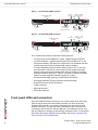
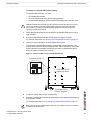
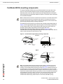
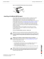
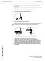
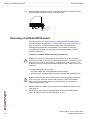
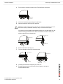
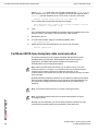
Turn both handles to their fully-closed positions.
The handles should hook into the sides of the chassis slot. Closing the handles
draws the FortiGate-5001A board into place in the chassis slot and into full
contact with the chassis backplane. The FortiGate-5001A front panel should be in
contact with the chassis front panel. For the FortiGate-5001A-DW, the right
(bottom) handle locks into place. For the FortiGate-5001A-SW, both handles lock
into place.
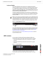
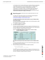
As the handles closed power is supplied to the board. If the chassis is powered on
the IPM LED starts flashing blue. If the board is aligned correctly, inserted all the
way into the slot, and the handles are properly closed the IPM LED flashes blue
for a few seconds. At the same time the STATUS LED flashes green, the interface
LEDs flash amber, and the ACC LED starts flashing green. After a few seconds
the IPM LED goes out and the FortiGate-5001A firmware starts up. During start
up the STATUS LED may continue to flash green. Once the board has started up
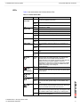
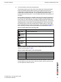
and is operating correctly, the front panel LEDs are lit as described in Table 4.
Table 4: FortiGate-5001A normal operating LEDs
LED
State
ACC
OOS
(Out of
Service)
Power
Status
IPM
Off (Or flashing green when the system accesses the
FortiGate-5001A flash disk.)
Off
Green
Off
Off
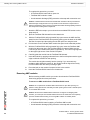
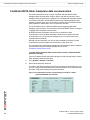
If you have installed an AMC module in the FortiGate-5001A board, the AMC
LEDs are lit as described in Table 5.
Table 5: FortiGate AMC module normal operating LEDs
LED
State
HS
Off
OOS
Off
PWR
Amber
OT
Off
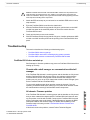
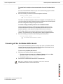
If the board has not been inserted properly the IPM LED changes to solid blue and
all other LEDS turn off. If this occurs, open the handles, slide the board part way
out, and repeat the insertion process.
FortiGate-5001A Security System Guide
01-30000-83456-20081023
17