1
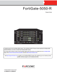
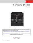
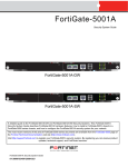
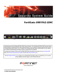
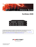
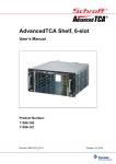
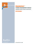
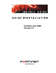
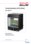
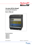
FortiGate-5050
Chassis Guide
CONSOLE
5
PWR ACC
4
PWR ACC
1
2
3
4
5
6
8
CONSOLE
USB
1
2
3
4
5
6
7
8
CONSOLE
USB
1
2
3
4
5
6
7
8
STA IPM
STA IPM
LED MODE
INT
FLT
OK
RESET
POWER
LED MODE
1
0
RESET
3
2
INT
FLT
5
4
EXT
FLT
7
6
OK
9
8
CLK
11
10
HOT SWAP
1
3
5
7
13
12
ZRE
15
14
ShMC
HOT SWAP
EXT
FLT
CLK
0
2
4
6
8
10
12
14
E1
E2
Z
R
E
2
Z
R
E
1
Z
R
E
0
R
S
2
3
2
E2
ZRE
9
11
13
15
Z
R
E
2
E1
Z
R
E
1
Z
R
E
0
R
S
2
3
2
SYSTEM
CONSOLE
SYSTEM
E
T
H
O
CONSOLE
MANAGEMENT
1
E
T
H
O
PWR ACC
2
2
7
STA IPM
MANAGEMENT
3
USB
ShMC
Critical
Major
Alarm
Alarm
Reset
Minor
Hot Swap
Status
Console
Ethernet
1
A detailed guide to the FortiGate-5050 chassis. This FortiGate-5050 Chassis Guide describes FortiGate-5050
hardware features, how to install the FortiGate-5050 chassis, and how to install FortiGate-5000 boards in the chassis.
The most recent versions of this and all FortiGate-5000 series documents are available from the FortiGate-5000 page
of the Fortinet Technical Documentation web site (http://docs.forticare.com).
Visit http://support.fortinet.com to register your FortiGate-5050 chassis. By registering you can receive product
updates, technical support, and FortiGuard services.
FortiGate-5050 Chassis Guide
01-30000-87211-20090106
Warnings and cautions
Warnings and cautions
Only trained and qualified personnel should be allowed to install or maintain FortiGate-5000 series equipment.
Read and comply with all warnings, cautions and notices in this document.
CAUTION: Risk of Explosion if Battery is replaced by an Incorrect Type. Dispose of Used Batteries According
to the Instructions.
Caution: You should be aware of the following cautions and warnings before installing FortiGate-5000 series
hardware
2
•
Turning off all power switches may not turn off all power to the FortiGate-5000 series equipment. Some circuitry
in the FortiGate-5000 series equipment may continue to operate even though all power switches are off.
•
Many FortiGate-5000 components are hot swappable and can be installed or removed while the power is on.
But some of the procedures in this document may require power to be turned off and completely disconnected.
Follow all instructions in the procedures in this document that describe disconnecting FortiGate-5000 series
equipment from power sources, telecommunications links and networks before installing, or removing
FortiGate-5000 series components, or performing other maintenance tasks. Failure to follow the instructions in
this document can result in personal injury or equipment damage.
•
Install FortiGate-5000 series chassis at the lower positions of a rack to avoid making the rack top-heavy and
unstable.
•
Do not insert metal objects or tools into open chassis slots.
•
Electrostatic discharge (ESD) can damage FortiGate-5000 series equipment. Only perform the procedures
described in this document from an ESD workstation. If no such station is available, you can provide some ESD
protection by wearing an anti-static wrist strap and attaching it to an available ESD connector such as the ESD
sockets provided on FortiGate-5000 series chassis.
•
Make sure all FortiGate-5000 series components have reliable grounding. Fortinet recommends direct
connections to the building ground.
•
If you install a FortiGate-5000 series component in a closed or multi-unit rack assembly, the operating ambient
temperature of the rack environment may be greater than room ambient. Make sure the operating ambient
temperature does not exceed Fortinet’s maximum rated ambient temperature.
•
Installing FortiGate-5000 series equipment in a rack should be such that the amount of airflow required for safe
operation of the equipment is not compromised.
•
FortiGate-5000 series chassis should be installed by a qualified electrician.
•
FortiGate-5000 series equipment shall be installed and connected to an electrical supply source in accordance
with the applicable codes and regulations for the location in which it is installed. Particular attention shall be
paid to use of correct wire type and size to comply with the applicable codes and regulations for the installation
/ location. Connection of the supply wiring to the terminal block on the equipment may be accomplished using
Listed wire compression lugs, for example, Pressure Terminal Connector made by Ideal Industries Inc. or
equivalent which is suitable for AWG 10. Particular attention shall be given to use of the appropriate
compression tool specified by the compression lug manufacturer, if one is specified.
FortiGate-5050 Chassis Guide
01-30000-87211-20090106
http://docs.fortinet.com/ • Feedback
Contents
Contents
Warnings and cautions................................................................................................... 2
FortiGate-5050 chassis............................................................................ 5
FortiGate-5050 front panel ............................................................................................. 6
FortiGate-5050 back panel ............................................................................................. 6
Physical description of the FortiGate-5050 chassis .................................................... 7
FortiGate-5050 shelf manager........................................................................................ 8
Shelf manager command line interface (CLI) ............................................................. 9
FortiGate-5050 shelf manager alarm functions ........................................................ 11
FortiGate-5050 shelf management functions............................................................ 12
Power connection and configuration................................................... 13
About data center DC power........................................................................................ 13
Connecting the FortiGate-5050 chassis to data center DC power and
data center ground........................................................................................................ 13
Connecting a FortiGate-5050 power input connector to data center
DC power.................................................................................................................. 13
Connecting the FortiGate-5050 chassis to data center ground ................................ 14
Connecting the FortiGate-5050 chassis to AC power using the
FortiGate-5053 power converter tray .......................................................................... 15
FortiGate-5053 power converter tray front and back panel ...................................... 15
Selecting the power supplies and power converter trays that you need
for your FortiGate-5050 configuration....................................................................... 17
Connecting a FortiGate-5050 chassis to the FortiGate-5053 power
converter tray............................................................................................................ 20
Turning on FortiGate-5050 chassis power ................................................................. 22
FortiGate-5050 hardware procedures .................................................. 23
Mounting the FortiGate-5050 chassis ......................................................................... 23
Air flow ...................................................................................................................... 23
Inserting 5000 series boards into a FortiGate-5050 chassis..................................... 23
Using FortiSwitch-5003A and FortiSwitch-5003 boards for backplane
communication.............................................................................................................. 24
For more information............................................................................. 25
Fortinet documentation ................................................................................................ 25
Fortinet Tools and Documentation CD ..................................................................... 25
Fortinet Knowledge Center ...................................................................................... 25
Comments on Fortinet technical documentation ..................................................... 25
Customer service and technical support.................................................................... 25
Register your Fortinet product .................................................................................... 25
FortiGate-5050 Chassis Guide
01-30000-87211-20090106
http://docs.fortinet.com/ • Feedback
3
Contents
4
FortiGate-5050 Chassis Guide
01-30000-87211-20090106
http://docs.fortinet.com/ • Feedback
FortiGate-5050 chassis
FortiGate-5050 chassis
You can install up to five FortiGate-5000 series boards in the five slots of the
FortiGate-5050 ATCA chassis. The FortiGate-5050 is a 5U 19-inch rackmount ATCA
chassis that contains two redundant DC power connections that connect to -48 VDC Data
Center DC power. The FortiGate-5050 chassis also includes a hot swappable cooling fan
tray. If all five slots contain FortiGate-5005FA2, FortiGate-5001SX, or FortiGate-5001FA2
boards, the FortiGate-5050 chassis provides a total of 40 1-Gigabit ethernet FortiGate
interfaces. If all 5 slots contain FortiGate-5001A boards the FortiGate-5050 chassis
supports 10 1-Gigabit ethernet FortiGate interfaces. If you add FortiGate-ADM-XB2
modules to the FortiGate-5001A boards the FortiGate-5050 chassis supports up to ten
10-Gigabit interfaces
You can also install FortiSwitch-5003A or FortiSwitch-5003 boards in the FortiGate-5050
chassis slots 1 and 2 to provide base backplane communications. Base backplane
communications can be used for HA heartbeat communications and data communications
using FortiGate-5050 base backplane channels. You can add a second FortiSwitch-5003A
or FortiSwitch-5003 board for redundancy. FortiSwitch-5003A boards can also provide
fabric backplane communication using the FortiGate-5050 fabric backplane channels.
You can mix and match any combination of FortiGate-5000 series boards in the
FortiGate-5050 chassis. For example, you could install two FortiGate-5005FA2 boards,
two FortiGate-5001SX boards, and one FortiGate-5001FA2 board. You can also install
FortiController-5208 and FortiGate-5005FA2 boards in a FortiGate-5050 chassis to create
a FortiGate-5005-DIST security system.
Some of the boards installed in a FortiGate-5050 chassis can be operating in a FortiGate
HA cluster and some can be operating as standalone FortiGate units. You can also
operate multiple HA clusters and standalone FortiGate units in a single FortiGate-5050
chassis. You can also use FortiSwitch-5003A or FortiSwitch-5003 boards to operate HA
clusters consisting of FortiGate-5000 series boards installed in multiple FortiGate-5000
chassis. You can also use FortiSwitch-5003A boards for fabric data communication
between chassis.
The FortiGate-5050 chassis also includes 5 rear transition module (RTM) slots. The
FortiGate-5050 chassis supports 10-gigabit fabric channel communication if you have
installed FortiGate-5001A boards with FortiGate-RTM-XB2 modules and one or two
FortiSwitch-5003A boards.
The FortiGate-5050 chassis requires -48VDC Data Center DC power. If DC power is not
available you can install a FortiGate-5053 power converter tray (purchased separately)
with FortiGate-5020/5050 power supplies.
This chapter describes the FortiGate-5050 chassis and includes the following sections:
•
FortiGate-5050 front panel
•
FortiGate-5050 back panel
•
Physical description of the FortiGate-5050 chassis
•
FortiGate-5050 shelf manager
FortiGate-5050 Chassis Guide
01-30000-87211-20090106
http://docs.fortinet.com/ • Feedback
5
FortiGate-5050 front panel
FortiGate-5050 chassis
FortiGate-5050 front panel
Figure 1 shows the front of a FortiGate-5050 chassis. Two FortiSwitch-5003 boards are
installed in slots 1 and 2. Three FortiGate-5001SX boards are installed in slots 3, 4, and 5.
The FortiGate-5050 primary Shelf Manager is also visible. The factory-installed shelf
managers provide power distribution, cooling, alarms, shelf status, and a telco alarm
interface for the FortiGate-5050 chassis. For more information about these components,
see “FortiGate-5050 shelf manager” on page 8.
Figure 1: FortiGate-5050 front panel with FortiGate-5001SX and FortiSwitch-5003 boards
installed
1
2
3
4
5
6
7
8
CONSOLE
USB
1
2
3
4
5
6
7
8
CONSOLE
USB
1
2
3
4
5
6
7
8
STA IPM
STA IPM
PWR ACC
STA IPM
2
INT
FLT
LED MODE
ShMC
Critical
Major
Alarm
Alarm
Reset
Minor
Hot-swappable
cooling fan tray
Power LED
POWER
LED MODE
OK
RESET
HOT SWAP
HOT SWAP
EXT
FLT
CLK
INT
FLT
6
EXT
FLT
8
OK
9
10
CLK
11
12
ZRE
13
14
ShMC
RESET
1
5
3
7
1
0
0
4
2
6
8
10
5
3
12
7
4
2
14
E1
15
E2
Z
R
E
2
Z
R
E
1
Z
R
E
0
R
S
2
3
2
E2
ZRE
9
11
13
Z
R
E
2
E1
15
Z
R
E
1
Z
R
E
0
R
S
2
3
2
SYSTEM
1
CONSOLE
2
SYSTEM
E
T
H
O
PWR ACC
MANAGEMENT
3
USB
CONSOLE
4
CONSOLE
PWR ACC
E
T
H
O
FortiSwitch-5003
boards
slots 1 and 2
5
MANAGEMENT
FortiGate-5001SX
boards
slots 3, 4,
and 5
Hot Swap
Status
Console
FortiGate-5050
Shelf Manager
Ethernet
1
ESD socket
Also visible on the front of the FortiGate-5050:
•
Electrostatic discharge (ESD) socket, used for connecting an ESD wrist or ankle band
when working with the chassis.
•
The location of the hot swappable FortiGate-5050 cooling fan tray behind panel.
•
Power LED.
Caution: Do not operate the FortiGate-5050 chassis with open slots on the front panel. For
optimum cooling performance and safety, the slots must contain a FortiGate-5000 series
board or an air baffle slot filler. As well the removable power supply panel must be installed
over the power connectors on the back of the chassis.
FortiGate-5050 back panel
Figure 2 shows the back panel of a FortiGate-5050 chassis. The back panel includes two
redundant -48V to - 58V DC power input connectors labelled Input A and Input B. The
power input connectors provide redundant DC power connections for the FortiGate-5050
chassis and distribute DC power to the fan tray and the FortiGate-5000 series boards
installed in the FortiGate-5050 chassis. Each power input connector includes a 24 Amp
circuit breaker that also functions as an on/off switch for the power input connector.
If you require redundant power you should connect both power input connectors to DC
power. If redundant power is not required, you should connect power input connector A to
DC power. When operating, the power input connectors are covered with clear protection
plates.
6
FortiGate-5050 Chassis Guide
01-30000-87211-20090106
http://docs.fortinet.com/ • Feedback
FortiGate-5050 chassis
Physical description of the FortiGate-5050 chassis
Figure 2: FortiGate-5050 chassis back panel
5
4
RTM
slot filler
panels
3
2
RTN
Power
wire
-48V
DC VOLTAGE RANGE
-48V TO -58V
RTN (-DC IN)
GND
Ground
Connector
(green)
RTN
1
INPUT A
-48V
DC VOLTAGE RANGE
-48V TO -58V
RTN (-DC IN)
INPUT B
25
AMP
Positive
(RTN)
(red)
-48V to -58V
Positive
(-DC in)
(RTN)
(black)
(red)
25
AMP
-48V to -58V
(-DC in)
(black)
ESD
k t
The back panel includes the FortiGate-5050 chassis ground connector which must be
connected to Data Center ground. Use the power wire fixtures for securing and managing
DC power wires. The FortiGate-5050 chassis also includes an ESD socket on the back
panel.
For detailed information about connecting power to the FortiGate-5050 chassis, see
“Connecting the FortiGate-5050 chassis to data center DC power and data center ground”
on page 13 or “Connecting the FortiGate-5050 chassis to AC power using the
FortiGate-5053 power converter tray” on page 15.
The back panel also contains 5 RTM slots numbered to correspond to the front panel
slots. The RTM slots are available for FortiGate-5000 RTM modules such as the
FortiGate-RTM-XB2 module. When the FortiGate-5050 chassis is shipped, these slots are
covered by RTM slot filler panels.
Physical description of the FortiGate-5050 chassis
The FortiGate-5050 chassis is a 5U chassis that can be installed in a standard 19-inch
rack. Table 1 describes the physical characteristics of the FortiGate-5050 chassis.
Table 1: FortiGate-5050 chassis physical description
Dimensions
8.75 x 17 x 15.5 in. (13.3 x 43.2 x 39.4 cm)
(H x W x D)
Weight
26.75 lb. (12.1 kg)
Operating environment
Temperature: 32 to 104°F (0 to 45°C)
Relative humidity: 5 to 85% (Non-condensing)
Storage environment
Temperature: -13 to 158 °F (-25 to 70°C)
Relative humidity: 5 to 95% (Non-condensing)
Power consumption
Maximum: 1,135 W
Power input
2x redundant -48VDC to -58VDC
FortiGate-5050 Chassis Guide
01-30000-87211-20090106
http://docs.fortinet.com/ • Feedback
7
FortiGate-5050 shelf manager
FortiGate-5050 chassis
FortiGate-5050 shelf manager
The FortiGate-5050 chassis includes one or two identical redundant hot-swappable shelf
managers (also called shelf manager cards (SMCs)), located in the dedicated shelf
manager slots on the bottom of the FortiGate-5050 front panel. The primary shelf manager
is installed on the right (SMC 1) the secondary shelf manager is installed on the left
(SMC 2).
The FortiGate-5050 shelf manager supports alarm and shelf management functions.
Figure 3: FortiGate-5050 shelf manager front panel
Critial, Major, and
Minor Alarm LEDs
Hot Swap and
Status LEDs
Critical
Major
Alarm
Retention
Screw
Handle
Alarm
Reset
Telco
Alarm
Interface
Minor
Alarm
LED
Reset
Button
Hot Swap
Status
Console
Ethernet
RS-232 10/100 base-T
Ethernet
Console
Port
Retention
Screw
Table 2 lists and describes the FortiGate-5050 shelf manager LEDs.
Table 2: FortiGate-5050 shelf manager LEDs
LED
State
Description
Critical
Major
Minor
Green
Normal operation
Red
Indicate the level of alarm: critical, major, or minor.
Hot Swap
Blue
LED is on when ready to be hot swapped.
Status
Green
Normal operation.
Ethernet
port
Yellow
Port is not forwarding packets.
Green
Blinking LED indicates network traffic.
Off
No link.
Table 3 lists and describes the FortiGate-5050 shelf manager connectors.
Table 3: FortiGate-5050 shelf manager connections
Connector Type
8
Speed
Protocol Description
Alarm
micro 9600 bps
DB-15
male
RS-232
serial
The external dry relay Telco alarm
interface (48VDC) provides Telco form-c
relay connections for minor, major and
critical power faults.
Console
RJ-45
9600 bps,
8/N/1
RS-232
serial
Serial connection to the command line
interface.
Ethernet
RJ-45
100Base-T
Ethernet
Provides access to Telnet , Web or SNMP
management methods.
FortiGate-5050 Chassis Guide
01-30000-87211-20090106
http://docs.fortinet.com/ • Feedback
FortiGate-5050 chassis
FortiGate-5050 shelf manager
Shelf manager command line interface (CLI)
You can use the shelf manager CLI to communicate with the intelligent management
controllers of the chassis, with boards in the chassis, and with the shelf manager itself.
The CLI is an IPMI-based set of commands that can be accessed directly or through a
higher-level management application or a script. Using the CLI, you can access
information about the current state of the chassis including current board population,
current sensor values, threshold settings, recent events, and overall chassis health.
Connecting to the shelf manager CLI using the console port
You can connect to the shelf manager CLI using the shelf manager RS-232 RJ-45 console
port. To connect this console port to a management PC you must use the Fortinet shelf
manager console adapter (FGSMC ADPTR 1). You cannot connect a standard nullmodem console cable to the shelf manager console port.
Figure 4: Connecting to the shelf manager console port
RS-232
Console
Port
Critical
Major
Alarm
Alarm
Reset
Minor
Hot Swap
Status
Console
Ethernet
FortiGate-5050 Shelf Manager
Standard
CAT5
RJ-45
Ethernet
Cable
Fortinet
Shelf Manager
Console
Adapter
Fortinet
RJ-45 to
9-pin
Console
Cable
To PC
RS-232
Console
Port
To connect to the shelf manager CLI using the shelf manager console port
1 Connect a standard CAT5 RJ-45 Ethernet cable to the shelf manager Console port.
2 Connect the other end of the Ethernet cable to the SMC side of the Fortinet shelf
manager console adapter (see Figure 4).
3 Connect the Fortinet console cable to the other side of the Fortinet shelf manager
console adapter (see Figure 4).
4 Connect the Fortinet console cable to your PC or other device RS-232 console port.
5 Start a terminal emulation program (for example, HyperTerminal) on the management
computer. Use these settings:
Baud Rate (bps)
9600
Data bits
8
Parity
None
Stop bits
1
Flow Control
None
6 Press enter to connect to the CLI.
FortiGate-5050 Chassis Guide
01-30000-87211-20090106
http://docs.fortinet.com/ • Feedback
9
FortiGate-5050 shelf manager
FortiGate-5050 chassis
7 At the login prompt enter the shelf manager user name and password.
The default user name is root with no password.
When you log into the shelf manager CLI you are logging into a Linux shell as root. The
following message appears. You can begin entering commands at the # prompt:
Welcome to
____ _ _
/ __| ||_|
_
_| | | | _ ____ _
_ _ _
| | | | | | || | _ \| | | |\ \/ /
| |_| | |__| || | | | | |_| |/
\
| ___\____|_||_|_| |_|\____|\_/\_/
| |
|_|
BusyBox v0.60.5 (2005.03.04-01:44+0000) Built-in shell (msh)
#
To add or change the shelf manager root account password
For enhanced security you should use the following steps to add a password for the shelf
manager root account.
1 At the # prompt enter the following Linux command to add a password for the root
account:
# passwd
2 Enter and confirm a new password for the root account.
The password should be between 5 and 8 characters long and should include a
combination of upper and lower case letters and numbers.
You can use the passwd command to change the root account password at any time.
You can also use the passwd command to remove the root account. Enter the passwd
command and when prompted for a password, press enter to add a blank password.
To use the shelf manager command line interface agent (CLIA)
Once you have logged into the shelf manager CLI you use the Command Line Interface
Agent (CLIA) to enter shelf manager commands. Usually you do this from the Linux
command line by entering clia followed by the required CLIA command verb and
parameters. The CLIA executable connects to the main Shelf Manager software process,
passes the command information to it and retrieves the results.
10
FortiGate-5050 Chassis Guide
01-30000-87211-20090106
http://docs.fortinet.com/ • Feedback
FortiGate-5050 chassis
FortiGate-5050 shelf manager
For example, you can enter the following command to list the most commonly used CLIA
commands:
clia help
You can also the help command to get more information about specific CLIA commands.
For example, use the following command display help for the shelf pwrreorder
command:
clia help shelf pwrreorder
Pigeon Point Shelf Manager Command Line Interpreter
Change the order of FRU Activation and Power Descriptors
instead of <addr> <fru_id> user may use:
board <N>
shm <N>
power_supply <N> (valid in 2.x systems only)
fan_tray <N>
PwrReorder <addr1> <fru_id1> before/after <addr2> <fru_id2>
FortiGate-5050 shelf manager alarm functions
The FortiGate-5050 shelf manager alarm functions provide LED indicators of
FortiGate-5050 alarms, a telco alarm connector, and an alarm LED reset button. The LED
alarm indicators include critical, major, and minor alarms.
The alarm LED reset button (RESET) on the shelf alarm panel activates the Alarm Cutoff
(ACO) state. When ACO is activated, the active alarm LED blinks and all of the alarm
relays are deactivated.
Shelf manager telco alarms
The shelf manager telco alarm interface relay circuits are capable of carrying 60 VDC or
1 A with a max. rating of 30 VA. The shelf manager accepts timed pulse inputs for clearing
minor and major alarm states. Reset is accomplished by asserting a voltage differential
from 3.3 V to 48 V for between 200 and 300 ms. The acceptance voltage range is from 0
to 48 VDC continuous (handles up to 60 VDC at a 50% duty cycle). The current drawn by
a reset input does not exceed 12 mA.
The alarm LED reset button activates the alarm cutoff (ACO) state for major, minor, and
user-defined alarms. You cannot reset critical alarms with the alarm LED reset button.
When the ACO state is activated, active alarm LEDs blink and all of the alarm relays are
deactivated. The alarm reset button activates the ACO state but does not clear the alarm
completely.
Figure 5: The telco alarm connector (DB-15 male)
15
8
FortiGate-5050 Chassis Guide
01-30000-87211-20090106
http://docs.fortinet.com/ • Feedback
9
1
11
FortiGate-5050 shelf manager
FortiGate-5050 chassis
Table 4: Telco alarm connector pin assignment
Pin
Name
Description
1
AMIR+
MinorReset+
2
AMIR-
MinorReset-
3
AMAR+
MajorReset+
4
AMAR-
MajorReset-
5
ACNO
CriticalAlarm - NO
6
ACNC
CriticalAlarm - NC
7
ACCOM
CriticalAlarm - COM
8
AMINO
MinorAlarm -NO
9
AMINC
MinorAlarm - NC
10
AMINCOM
MinorAlarm - COM
11
AMANO
MajorAlarm - NO
12
AMANC
MajorAlarm - NC
13
AMACOM
MajorAlarm - COM
14
APRCO
PwrAlarm - NO
15
APRCOM
PwrAlarm - COM
Shield
Shelf-GND
Shelf Ground
FortiGate-5050 shelf management functions
The shelf managers support redundant operation with automatic switchover. If both shelf
managers are operating normally, one acts as the active shelf manager and the other as
the standby. Usually the primary shelf manager would be the active shelf manager and the
secondary shelf manager would be the standby shelf manager. The shelf managers
monitor each other and either can trigger a switchover if necessary. The active shelf
manager performs all shelf manager functions. If the active shelf manager fails or is
removed, the standby shelf manager takes over all shelf manager functions.
The FortiGate-5050 shelf managers control chassis power up and power down, chassis
power distribution, monitor chassis operating parameters, monitor and control chassis
cooling, and can signal alarms if the chassis encounters problems. All FortiGate-5000
boards installed in the chassis communicate with the shelf managers.
The FortiGate-5050 shelf managers are factory installed. In most cases users do not have
to install or configure the shelf managers.
Each shelf manager has one ethernet interface (ETH 0 and ETH 1). You can connect to
ETH 0 from the shelf manager front panel. ETH 1 connects to the FortiGate-5050
backplane.
The shelf managers are hot swappable. You can remove a shelf manager by opening the
handle until the hot swap LED starts blinking. When the hot swap LED turns solid blue you
can remove the shelf manager from the FortiGate-5050 chassis.
12
FortiGate-5050 Chassis Guide
01-30000-87211-20090106
http://docs.fortinet.com/ • Feedback
Power connection and configuration
Power connection and configuration
This chapter describes how to connect data center DC power to a FortiGate-5050 chassis.
If data center DC power is not available, this document also describes how to use the
FortiGate-5053 power converter tray to supply DC power to the FortiGate-5050 chassis.
This chapter describes:
•
About data center DC power
•
Connecting the FortiGate-5050 chassis to data center DC power and data center
ground
•
Connecting the FortiGate-5050 chassis to AC power using the FortiGate-5053 power
converter tray
•
Turning on FortiGate-5050 chassis power
About data center DC power
The FortiGate-5050 chassis is designed to be installed in a data center or similar location
that has available -48VDC power (also called battery power). Fortinet expects that most
FortiGate-5050 customers will be installing their FortiGate equipment in a data center or
similar location that is already equipped with a -48VDC power system that provides power
to existing networking or telecom equipment. The FortiGate-5050 chassis are designed to
be connected directly to this DC power system.
In this document, data center DC power refers to a -48VDC power system that is already
available at the location at which the FortiGate-5050 chassis is being installed.
Connecting the FortiGate-5050 chassis to data center DC power
and data center ground
Connect the FortiGate-5050 chassis to data center DC power using the redundant power
input connectors on the FortiGate-5050 back panel. Fortinet supplies and recommends
AWG-14 stranded wires for all power connections: Black for -48VDC and red for RTN.
Green AWG-6 wires are recommended for ground connections. If required, install terminal
lugs on the wires before connecting them to the power input connectors.
This section describes:
•
Connecting a FortiGate-5050 power input connector to data center DC power
•
Connecting the FortiGate-5050 chassis to data center ground
Connecting a FortiGate-5050 power input connector to data center DC power
The following procedure describes how to connect one FortiGate-5050 power input
connector to data center DC power. For normal operation, only power input connector A
must be connected. For redundant DC power you can connect power input connector B to
a different DC power source.
FortiGate-5050 Chassis Guide
01-30000-87211-20090106
http://docs.fortinet.com/ • Feedback
13
Connecting the FortiGate-5050 chassis to data center DC power and data center ground
Figure 6: Connecting a FortiGate-5050 power input connector to data center DC power
Data Center
RTN connector
Data Center
-48VDC
connector
RTN (positive)
red to Data
Center RTN
-48V to -58V
(-DC in) black to
Data Center -48VDC
Power wire
fixture
Positive
(RTN)
(red)
-48V to -58V
(-DC in)
(black)
To connect a FortiGate-5050 power input connector to data center DC power
You need the following tools and equipment to connect a FortiGate-5050 power input
connector to data center DC power:
•
A number 2 Phillips screwdriver.
•
An electrostatic discharge (ESD) preventive wrist or ankle strap with connection cord.
•
One black AWG-14 stranded wire with terminal lugs attached and labelled -48V.
•
One red AWG-14 stranded wire with terminal lugs attached and labelled RTN.
1 Attach the ESD wrist strap to your wrist and to an ESD socket or to a bare metal
surface on the chassis or frame.
2 Loosen the screws and remove the protection plate.
3 Insert the black -48V and red RTN wires through the power wire fixture (see Figure 6).
4 Connect the black -48V power wire from the data center DC power source to the
terminal on the FortiGate-5050 power input connector labelled (-DC in).
5 Connect the red RTN return wire from data center RTN to the terminal on the
FortiGate-5050 power input connector labelled RTN.
6 Make sure the power wires are secured to the chassis using the power wire fixture and
tie wraps if required.
7 If required, label the black wire -48V.
8 If required, label the red wire RTN.
9 Re-attach the protection plate to the FortiGate-5050 power input connector.
Connecting the FortiGate-5050 chassis to data center ground
The FortiGate-5050 chassis has a ground connections on the lower left side of the
FortiGate-5050 back panel (see Figure 2 on page 7). This connector must be connected
to data center ground.
14
FortiGate-5050 Chassis Guide
01-30000-87211-20090106
http://docs.fortinet.com/ • Feedback
Power connection and configuration
To connect the FortiGate-5050 chassis to data center ground
You need the following tools and equipment to connect the FortiGate-5050 chassis to
ground:
•
A number 2 Phillips screwdriver.
•
An electrostatic discharge (ESD) preventive wrist or ankle strap with connection cord.
•
One green AWG-6 stranded wire with terminal lugs attached.
Figure 7: Connecting a FortiGate-5050 chassis to data center ground
Data Center
ground
connector
FortiGate-5050
Ground
connector
1 Attach the ESD wrist strap to your wrist and to an ESD socket or to a bare metal
surface on the chassis or frame.
2 Connect the green ground wire from the data center ground to the ground connector on
the FortiGate-5050 chassis (see Figure 7).
3 Secure the ground wire to the chassis.
4 Optionally label the wire GND.
Connecting the FortiGate-5050 chassis to AC power using the
FortiGate-5053 power converter tray
If data center DC power is not available, you can use the FortiGate-5053 power converter
tray with FortiGate-5020/5050 power supplies (shown in Figure 8) to convert AC power to
DC power. The FortiGate-5053 power converter tray and the power supplies are not
supplied with the FortiGate-5050 chassis and must be purchased separately. (FortiGate5020/5050 power supplies are also used to provide power to a FortiGate-5020 chassis.)
This section contains the following information about the FortiGate-5050 chassis and the
FortiGate-5053 power converter tray:
•
FortiGate-5053 power converter tray front and back panel
•
Selecting the power supplies and power converter trays that you need for your
FortiGate-5050 configuration
•
Connecting a FortiGate-5050 chassis to the FortiGate-5053 power converter tray
FortiGate-5053 power converter tray front and back panel
The front panel of the FortiGate-5053 power converter tray (shown in Figure 8) provides
access to the FortiGate-5020/5050 power supplies.
FortiGate-5050 Chassis Guide
01-30000-87211-20090106
http://docs.fortinet.com/ • Feedback
15
Connecting the FortiGate-5050 chassis to AC power using the FortiGate-5053 power converter tray
Figure 8: Front panel of the FortiGate-5053 power converter tray with one power supply
removed
AC Power
LED DC Power
LED
Slot 3
Slot 1
Slot 2
The LEDs for each installed power supply are visible from the FortiGate-5053 power
converter tray front panel.
Table 5: FortiGate-5020/5050 power supply LEDs
LED
State
Description
AC Power
Green
The power supply is connected to AC power.
Off
The power supply is not receiving DC power. This can happen if an AC
cable is not connected, if the power supply is not correctly installed in
the slot, or if the power supply is not functioning.
Green
The power supply is providing DC power.
Off
The power supply is not providing DC power. If the AC power LED is lit
and the DC power LED is not, the power supply is not functioning
correctly and should be replaced. This LED can also go off if the power
supply overheats. If this happens the power supply stops supplying DC
power. After the power supply cools down in will start supplying DC
power again and this LED lights.
DC Power
The back panel of the FortiGate-5053 (shown in Figure 9) includes one DC power
connector terminal consisting of a RTN connector and a -48VDC connector.
•
The -48VDC connector is labelled V- and may also be labelled with -48V (BLACK).
•
The RTN connector is labelled V+ and may also be labelled RTN (RED)
Figure 9: Back panel of the FortiGate-5053 power converter tray
RTN(RED) -48V(BL ACK)
V+
V+
(RTN)
(RED)
100-240VAC 1
2
3
V-
V-48V
(BLACK)
DC out
AC in
The back panel also includes three AC power connectors numbered 1, 2, 3. The AC
connector numbering corresponds to the slot numbering showing in Figure 8. Each
connector connects AC power directly to a FortiGate-5020/5050 power supply. The
FortiGate-5053 can contain 1, 2, or 3 FortiGate-5020/5050 power supplies depending on
your requirements. You should only connect AC power to the power supplies that are
installed.
16
FortiGate-5050 Chassis Guide
01-30000-87211-20090106
http://docs.fortinet.com/ • Feedback
Power connection and configuration
AC input power characteristics:
•
AC input voltage: 110 to 250 VAC
•
AC input current: 10A
•
Frequency: 47 to 63 Hz
Selecting the power supplies and power converter trays that you need for your
FortiGate-5050 configuration
This section provides some basic information for determining how many FortiGate-5053
power converter trays and FortiGate-5020/5050 power supplies that you need, depending
on the power requirements of your FortiGate-5050 chassis. This section provides
guidelines only. Actual requirements may vary depending on your installation
requirements. Contact Fortinet Technical Support if you need more information.
The FortiGate-5053 power converter tray contains space for up to three
FortiGate-5020/5050 power supplies. A FortiGate-5020/5050 power supply converts AC
power to -48 VDC power. Each FortiGate-5020/5050 power supply provides 800W of
power.
The FortiGate-5053 power converter tray uses 2 + 1 power supply redundancy. If three
FortiGate-5020/5050 power supplies are installed in a FortiGate-5053 power converter
tray, the first two power supplies provide a total of 1600W (2 x 800W) of power. The third
power supply is the redundant backup.
The maximum power output for a FortiGate-5053 power converter tray with FortiGate5020/5050 power supplies is 1600W; which can be achieved with two FortiGate5020/5050 power supplies. If you need 1600W of power and power supply redundancy,
you can add a third FortiGate-5020/5050 power supply.
Individual power requirements vary. If 800W is enough power and redundancy is not
required, you need one FortiGate-5053 power converter tray and one FortiGate5020/5050 power supply.
If 800W is sufficient but a redundant power supply is required, you can add a second
FortiGate-5020/5050 power supply. This second power supply will also cover power
requirements between 800 and 1600W. If you require redundant power greater than 800W
you can add a third FortiGate-5020/5050 power supply.
Basic power requirements
To supply enough power for a FortiGate-5050 chassis with a total of five FortiGate boards
and FortiSwitch boards you require one FortiGate-5053 power converter tray and two
FortiGate-5020/5050 power supplies (see Figure 10). The FortiGate-5020/5050 power
supplies are installed in FortiGate-5053 slots 1 and 2. This configuration supplies 1600W
of power to the FortiGate-5020/5050 chassis.
Note: If your will not be filling all of the FortiGate-5050 slots you may not need both
FortiGate-5020/5050 power supplies.
FortiGate-5050 Chassis Guide
01-30000-87211-20090106
http://docs.fortinet.com/ • Feedback
17
Connecting the FortiGate-5050 chassis to AC power using the FortiGate-5053 power converter tray
Figure 10: Non-redundant power for all FortiGate-5050 chassis slots
1 FortiGate-5053
power convertor tray
Slot 3
Slot 2
Slot 1
2 FortiGate-5020/5050
power supplies
2 x 800W = 1600W
5
USB
1
2
3
4
5
6
7
8
CONSOLE
USB
1
2
3
4
5
6
7
8
CONSOLE
USB
1
2
3
4
5
6
7
8
STA IPM
STA IPM
OK
INT
FLT
LED MODE
POWER
LED MODE
1
5
3
HOT SWAP
ZRE
0
4
2
CLK
EXT
FLT
OK
1
INT
FLT
5
3
0
ZRE
4
2
CLK
EXT
FLT
E1
HOT SWAP
8
6
9
7
8
6
14
E2
ShMC
RESET
14
12
10
E2
15
13
11
12
10
Z
R
E
2
Z
R
E
1
Z
R
E
0
R
S
2
3
2
RESET
Z
R
E
2
9
7
Z
R
E
1
E1
15
13
11
Z
R
E
0
R
S
2
3
2
SYSTEM
1
CONSOLE
E
T
H
O
STA IPM
2
SYSTEM
PWR ACC
CONSOLE
3
MANAGEMENT
PWR ACC
E
T
H
O
4
MANAGEMENT
1 FortiGate-5050
chassis
CONSOLE
PWR ACC
ShMC
Critical
Major
2
Alarm
Hot Swap
Status
Minor
Alarm
Reset
Console
Ethernet
1
Redundant FortiGate-5050 power supplies
You can supply redundant power to a FortiGate-5050 chassis by adding a third
FortiGate-5020/5050 power supply to the FortiGate-5053 power converter tray
(see Figure 11). If one of the FortiGate-5020/5050 power supplies in the FortiGate-5053
power converter tray fails, the third power supply takes its place without a power
interruption.
Figure 11: 2 + 1 redundant FortiGate-5020/5050 power supplies
1 FortiGate-5053
power convertor tray
Slot 3
Slot 2
Slot 1
3 FortiGate-5020/5050
power supplies
2 x 800W = 1600W
2 + 1 redundancy
USB
1
2
3
4
5
6
7
8
CONSOLE
USB
1
2
3
4
5
6
7
8
CONSOLE
USB
1
2
3
4
5
6
7
8
STA IPM
2
LED MODE
POWER
LED MODE
OK
1
7
5
3
HOT SWAP
INT
FLT
OK
INT
FLT
ZRE
6
RESET
ZRE
0
6
4
2
CLK
1
EXT
FLT
7
5
3
0
CLK
EXT
FLT
HOT SWAP
4
2
9
8
8
11
10
10
14
12
E2
E1
15
13
14
12
E2
ShMC
RESET
9
11
E1
15
13
Z
R
E
1
Z
R
E
0
Z
R
E
2
Z
R
E
2
CONSOLE
Z
R
E
1
Z
R
E
0
CONSOLE
R
S
2
3
2
SYSTEM
1
R
S
2
3
2
STA IPM
2
SYSTEM
PWR ACC
E
T
H
O
3
CONSOLE
STA IPM
MANAGEMENT
PWR ACC
E
T
H
O
PWR ACC
4
MANAGEMENT
1 FortiGate-5050
chassis
5
ShMC
Critical
Major
Alarm
Alarm
Reset
Minor
Hot Swap
Status
Console
Ethernet
1
Redundant FortiGate-5053 power converter trays
A single FortiGate-5053 power converter tray is usually only connected to one
FortiGate-5050 power input connector. If this power input connector or FortiGate-5053
power converter tray fails or is disconnected the FortiGate-5050 chassis will loose power.
You can supply redundant power to the entire FortiGate-5050 chassis by adding a second
FortiGate-5053 power converter containing two or three FortiGate-5020/5050 power
supplies and connected this FortiGate-5053 power converter tray to the second
FortiGate-5050 power input connector.
18
FortiGate-5050 Chassis Guide
01-30000-87211-20090106
http://docs.fortinet.com/ • Feedback
Power connection and configuration
Figure 12: Redundant FortiGate-5053 power converter trays
Slot 3
Slot 2
Slot 1
Slot 3
Slot 2
Slot 1
2 FortiGate-5053
power convertor trays
4 FortiGate-5020/5050
power supplies
2 x 800W = 1600W
2 x 800W = 1600W
5
USB
1
2
3
4
5
6
7
8
CONSOLE
USB
1
2
3
4
5
6
7
8
CONSOLE
USB
1
2
3
4
5
6
7
8
STA IPM
STA IPM
OK
INT
FLT
1
LED MODE
POWER
LED MODE
OK
INT
FLT
6
ZRE
CLK
EXT
FLT
ShMC
RESET
7
5
3
ZRE
0
6
4
2
CLK
1
EXT
FLT
7
5
3
0
HOT SWAP
4
2
8
9
8
10
11
10
E2
RESET
HOT SWAP
Z
R
E
2
9
11
Z
R
E
1
Z
R
E
0
R
S
2
3
2
E1
15
13
14
12
E2
E1
15
13
14
12
Z
R
E
2
Z
R
E
1
Z
R
E
0
R
S
2
3
2
SYSTEM
1
CONSOLE
E
T
H
O
STA IPM
2
SYSTEM
PWR ACC
CONSOLE
3
MANAGEMENT
PWR ACC
E
T
H
O
4
MANAGEMENT
1 FortiGate-5050
chassis
CONSOLE
PWR ACC
ShMC
Critical
Major
2
Alarm
Alarm
Reset
Hot Swap
1
Status
Minor
Console
Ethernet
Figure 13: Redundant FortiGate-5053 power converter trays and 2 + 1 redundant FortiGate5020/5050 power supplies
Slot 3
Slot 2
Slot 1
Slot 3
Slot 2
Slot 1
2 FortiGate-5053
power convertor trays
6 FortiGate-5020/5050
power supplies
2 x 800W = 1600W
2 + 1 redundancy
2 x 800W = 1600W
2 + 1 redundancy
USB
1
2
3
4
5
6
7
8
CONSOLE
USB
1
2
3
4
5
6
7
8
CONSOLE
USB
1
2
3
4
5
6
7
8
STA IPM
STA IPM
FortiGate-5050 Chassis Guide
01-30000-87211-20090106
http://docs.fortinet.com/ • Feedback
LED MODE
RESET
HOT SWAP
POWER
LED MODE
HOT SWAP
OK
INT
FLT
RESET
OK
INT
FLT
5
3
9
7
11
1
0
4
2
8
6
10
CLK
1
ZRE
10
CLK
EXT
FLT
15
13
14
12
E2
ShMC
2
EXT
FLT
5
3
9
7
0
11
4
2
8
6
14
12
E2
Z
R
E
2
E1
ZRE
15
13
Z
R
E
2
E1
Z
R
E
0
Z
R
E
1
Z
R
E
1
SYSTEM
CONSOLE
Z
R
E
0
R
S
2
3
2
1
R
S
2
3
2
STA IPM
2
SYSTEM
PWR ACC
E
T
H
O
3
MANAGEMENT
PWR ACC
E
T
H
O
4
MANAGEMENT
1 FortiGate-5050
chassis
CONSOLE
PWR ACC
CONSOLE
5
ShMC
Critical
Major
Alarm
Alarm
Reset
Minor
Hot Swap
Status
Console
Ethernet
1
19
Connecting the FortiGate-5050 chassis to AC power using the FortiGate-5053 power converter tray
Connecting a FortiGate-5050 chassis to the FortiGate-5053 power converter tray
To use a FortiGate-5053 power converter tray with the FortiGate-5050 chassis you need
to make DC power connections between the FortiGate-5050 chassis and the FortiGate5053 power converter tray. You also need to the connect the FortiGate-5050 chassis to
data center ground.
To connect a FortiGate-5050 power input connector to a FortiGate-5053 power
converter tray
The following procedure describes how to connect one FortiGate-5050 power input
connector to a FortiGate-5053 power converter tray. For normal operation, only one power
input connector must be connected. For redundant chassis DC power you can connect the
second power input connector to a second FortiGate-5053 power converter tray.
You need the following tools and equipment to connect a FortiGate-5020/5050 power
input connector to a FortiGate-5053 power converter tray:
•
A number 2 Phillips screwdriver.
•
An electrostatic discharge (ESD) preventive wrist or ankle strap with connection cord.
•
One black AWG-14 stranded wire with terminal lugs attached and labelled -48V.
•
One red AWG-14 stranded wire with terminal lugs attached and labelled RTN.
•
A FortiGate-5053 power converter tray containing two or three FortiGate-5020/5050
power supplies and mounted in a rack near the FortiGate-5050 chassis.
Caution: The FortiGate-5053 power converter tray should not be connected to AC power
until specified in the following procedure.
1 Attach the ESD wrist strap to your wrist and to an ESD socket or to a bare metal
surface on the chassis or frame.
2 Loosen the screws and remove the protection plate from the FortiGate-5050 power
input connector.
3 If required, loosen the screws and remove the clear plastic cover from the back of the
FortiGate-5053 power converter tray.
4 Insert the black -48V and red RTN wires through the power wire fixture (see Figure 14).
5 Connect the black -48V power wire from the FortiGate-5053 power converter tray Vterminal (the right connector) to the terminal on the FortiGate-5050 power input
connector labelled (-DC in).
6 Connect the red RTN return wire from the FortiGate-5053 power converter tray
unmarked connector (the left connector) to the terminal on the FortiGate-5050 power
input connector labelled RTN.
20
FortiGate-5050 Chassis Guide
01-30000-87211-20090106
http://docs.fortinet.com/ • Feedback
Power connection and configuration
Figure 14: Connecting a FortiGate-5050 power input connector to a FortiGate-5053 power
converter tray
V+
(RTN)
(RED)
V-48V
(BLACK)
AC in
Red RTN to
FortiGate-5053
RTN
-48V/-58 VDC black to
FortiGate-5053
-48/-58 VDC
Power wire
fixture
-48V/-58V
-DC in
Positive (RTN) (red) (black)
7 Make sure the power wires are secured to the chassis using the power wire fixture and
tie wraps if required.
8 If required, label the black wires -48V.
9 If required, label the red wires RTN.
10 Re-attach the protection plate to the FortiGate-5050 power input connector.
11 Attach the clear plastic cover to the back of the FortiGate-5053 power converter tray.
12 Connect the FortiGate-5053 power converter tray to AC power.
Only connect the power supplies that are installed in the FortiGate-5053 to AC power.
For example, if your FortiGate-5053 includes two FortiGate-5020/5050 power supplies,
the power supplies will be installed in slots 1 and 2. In this case you should only
connect AC in connectors 1 and 2 to AC power. If your FortiGate-5053 power converter
tray contains three power supples, connect all three AC in connectors to AC power.
The photograph in Figure 15 shows the back panel of a FortiGate-5053 wired to provide
power to a FortiGate-5050 chassis. This photograph also shows the clear back cover of
the FortiGate-5053 installed. You should install this cover using the mounting hardware
provided. Install the cover after connecting the power but before turning the power on.
FortiGate-5050 Chassis Guide
01-30000-87211-20090106
http://docs.fortinet.com/ • Feedback
21
Turning on FortiGate-5050 chassis power
Figure 15: Wiring the FortiGate-5053 power converter tray
To connect the FortiGate-5050 chassis to data center ground
The FortiGate-5053 power converter tray does not have a ground connector. So, even if
you are using a FortiGate-5053 power converter tray to supply DC power to your
FortiGate-5050, you must use the procedure “To connect the FortiGate-5050 chassis to
data center ground” on page 15 to connect the FortiGate-5050 to data center ground.
Turning on FortiGate-5050 chassis power
If you are using a FortiGate-5053 power converter, connect the FortiGate-5053 power
converter to AC power. When the FortiGate-5020/5050 power supplies start up the power
supply fans should begin operating. Each FortiGate-5020/5050 power supply has two
front panel power LEDs (see Figure 8 on page 16). When the FortiGate-5053 power
converter is operating normally, both of the FortiGate-5020/5050 power supply LEDs
should be lit for each connected power supply.
If you are using data center DC power, turn own the power to the chassis according to the
requirements of your data center DC power system.
Once the FortiGate-5050 chassis is connected to DC power you can turn on power to the
chassis by switching on the circuit breakers at the back of the chassis (see Figure 2 on
page 7 for location of the circuit breakers).
The FortiGate-5050 chassis powers up. If the FortiGate-5050 is operating correctly, the
Power LED on the right side of the chassis front panel should be lit (see Figure 1 on
page 6). As well, the Status LED on the FortiGate-5050 shelf manager front panels should
be lit (see Figure 3 on page 8).
When the chassis first starts up you should also hear the cooling fans operating.
In addition, if any FortiGate-5000 series boards have been installed in the chassis they
should power on and their front panel LEDs should indicate that they are operating
normally.
22
FortiGate-5050 Chassis Guide
01-30000-87211-20090106
http://docs.fortinet.com/ • Feedback
FortiGate-5050 hardware procedures
Mounting the FortiGate-5050 chassis
FortiGate-5050 hardware procedures
This chapter assumes the chassis has been mounted and connected to a power source
as detailed in “Power connection and configuration” on page 13.
This chapter discusses:
•
Mounting the FortiGate-5050 chassis
•
Inserting 5000 series boards into a FortiGate-5050 chassis
•
Using FortiSwitch-5003A and FortiSwitch-5003 boards for backplane communication
Mounting the FortiGate-5050 chassis
Note: Mount the FortiGate chassis before installing the FortiGate-5000 series boards.
The FortiGate-5050 chassis must be mounted in a standard 19-inch rack. The chassis
requires 5U of vertical space in the rack.
If you install the FortiGate-5050 chassis in a closed or multi-unit rack assembly, the
operating ambient temperature of the rack environment may be greater than room
ambient temperature. Make sure the operating ambient temperature does not exceed the
manufacturer's maximum rated ambient temperature.
Caution: The FortiGate-5050 chassis should not be operated as a free-standing appliance.
Air flow
For rack installation, make sure that the amount of air flow required for safe operation of
the FortiGate-5050 chassis is not compromised.
Inserting 5000 series boards into a FortiGate-5050 chassis
You can insert FortiGate-5000 series and FortiSwitch boards into the FortiGate-5050
chassis. Arrange the boards in slots as required for your configuration. FortiGate-5000
series boards can be installed in any FortiGate-5050 slots. FortiSwitch-5003 boards can
only be installed in switch slots 1 and 2.
Your FortiGate-5050 chassis may have been shipped with temporary slot filler panels that
include a warning message to read the FortiGate-5000 documentation before installing
your product. The temporary slot fillers must be removed and all slots filled; either with
FortiGate-5000 series boards or with air baffle slot fillers. Air baffle slot fillers are similar to
blank FortiGate-5000 boards and are required for proper cooling air flow.
FortiGate-5050 Chassis Guide
01-30000-87211-20090106
http://docs.fortinet.com/ • Feedback
23
Using FortiSwitch-5003A and FortiSwitch-5003 boards for backplane communication
FortiGate-5050 hardware procedures
Caution: FortiGate-5000 series and FortiSwitch-5000 series boards must be protected
from static discharge and physical shock. Only handle or work with FortiGate-5000 series
and FortiSwitch-5000 series boards at a static-free workstation. Always wear a grounded
electrostatic discharge (ESD) preventive wrist or ankle strap when handling FortiGate-5000
series or FortiSwitch-5000 series boards.
Caution: Do not operate the FortiGate-5050 chassis with open slots on the front panel or
rear panel. For optimum cooling performance and safety, front panel slots must contain a
FortiGate-5000 series board or an air baffle slot filler and rear panel slots must either be
covered or must contain a rear transition board or slot filler. As well the removable PEM
terminal block covers must be installed over the power connectors on the back of the
chassis.
See the following documents for information about installing and removing the following
FortiGate-5000 series and FortiSwitch-5000 series boards:
FortiGate-5001A
•
FortiGate-5001A Security System Guide
FortiGate-5005FA2:
•
FortiGate-5005FA2 Security System Guide
FortiGate-5001SX:
•
FortiGate-5001SX Security System Guide
FortiGate-5001FA2:
•
FortiGate-5001FA2 Security System Guide
FortiSwitch-5003A
•
FortiSwitch-5003A System Guide
FortiGate-RTM-XB2
•
FortiGate-RTM-XB2 System Guide
FortiSwitch-5003
•
FortiSwitch-5003 System Guide
Using FortiSwitch-5003A and FortiSwitch-5003 boards for
backplane communication
FortiSwitch-5003A boards installed in a FortiGate-5050 chassis in slot 1 or slot 2 provide
fabric backplane switching for all of the FortiGate-5000 series boards installed in chassis
slots 3 and above. Fabric backplane switching is most often used for data communication
between FortiGate-5000 series boards in a chassis, between chassis, and between the
chassis and the network.
FortiSwitch-5003A and 5003 boards installed in a FortiGate-5050 chassis in slot 1 or slot 2
provide base backplane switching for all of the FortiGate-5000 series boards installed in
chassis slots 3 and above. Base backplane switching is usually used for HA heartbeat
communication between FortiGate-5000 series boards in HA clusters.
For complete information about using the FortiSwitch-5003A and 5003 for backplane
communications (including the FortiSwitch-5003A CLI reference), see the
FortiSwitch-5003A and 5003 Fabric and Base Backplane Communication Guide.
24
FortiGate-5050 Chassis Guide
01-30000-87211-20090106
http://docs.fortinet.com/ • Feedback
For more information
Fortinet documentation
For more information
Support for your Fortinet product is available as online help from within the web-based
manager, from the Tools and Documentation CD included with the product, on the Fortinet
Technical Documentation web site, from the Fortinet Knowledge Center web site, as well
as from Fortinet Technical Support.
Fortinet documentation
The most up-to-date publications and previous releases of Fortinet product documentation
are available from the Fortinet Technical Documentation web site at
http://docs.forticare.com. FortiGate-5000 series documentation is located in its own
section of the site at http://docs.forticare.com/fgt5k.html.
Fortinet Tools and Documentation CD
Fortinet documentation is available from the Fortinet Tools and Documentation CD
shipped with your Fortinet product. The documents on this CD are current for your product
at shipping time. For the latest versions of all Fortinet documentation see the Fortinet
Technical Documentation web site at http://docs.forticare.com.
Fortinet Knowledge Center
Additional information about Fortinet products is available from the Fortinet Knowledge
Center. The knowledge center contains troubleshooting and how-to articles, FAQs,
technical notes, and more. Visit the Fortinet Knowledge Center at http://kc.forticare.com.
Comments on Fortinet technical documentation
Please send information about any errors or omissions in this document, or any Fortinet
technical documentation, to [email protected].
Customer service and technical support
Fortinet Technical Support provides services designed to make sure that your Fortinet
systems install quickly, configure easily, and operate reliably in your network.
Please visit the Fortinet Technical Support web site at http://support.fortinet.com to learn
about the technical support services that Fortinet provides.
Register your Fortinet product
Register your Fortinet product to receive Fortinet customer services such as product
updates and technical support. You must also register your product for FortiGuard
services such as FortiGuard Antivirus and Intrusion Prevention updates and for
FortiGuard Web Filtering and AntiSpam.
Register your product by visiting http://support.fortinet.com and selecting Product
Registration.
To register, enter your contact information and the serial numbers of the Fortinet products
that you or your organization have purchased. You can register multiple Fortinet products
in a single session without re-entering your contact information.
FortiGate-5050 Chassis Guide
01-30000-87211-20090106
http://docs.fortinet.com/ • Feedback
25
Register your Fortinet product
For more information
© Copyright 2009 Fortinet, Inc. All rights reserved. No part of this publication
including text, examples, diagrams or illustrations may be reproduced,
transmitted, or translated in any form or by any means, electronic, mechanical,
manual, optical or otherwise, for any purpose, without prior written permission of
Fortinet, Inc.
Trademarks
Fortinet, FortiGate and FortiGuard are registered trademarks and Dynamic Threat
Prevention System (DTPS), APSecure, FortiASIC, FortiBIOS, FortiBridge,
FortiClient, FortiGate, FortiGate Unified Threat Management System, FortiGuardAntispam, FortiGuard-Antivirus, FortiGuard-Intrusion, FortiGuard-Web, FortiLog,
FortiAnalyzer, FortiManager, FortiOS, FortiPartner, FortiProtect, FortiReporter,
FortiResponse, FortiShield, and FortiVoIP, are trademarks of Fortinet, Inc. in the
United States and/or other countries. The names of actual companies and
products mentioned herein may be the trademarks of their respective owners.
Regulatory compliance
FCC Class A, Part 15
CE mark
VCCI
C-Tick
UL/CUL
26
FortiGate-5050 Chassis Guide
01-30000-87211-20090106
http://docs.fortinet.com/ • Feedback