1
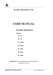
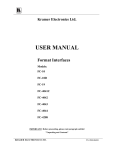
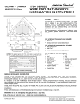
dual manager User manual
We thank you for choosing Focal amplifiers for your Car Audio system and for sharing
our philosophy: “the Spirit of Sound”. This product offers the latest advances in
Focal amplifiers. In order to obtain the best results, we highly recommend you have
your new amplifier installed by your local Focal distributor. To maximise the use
all the functionalities of your amplifier and to fully enjoy its performance levels,
we recommend that you read the entire instructions in this booklet, as well as the
Focal Dual Monitor software manual. We recommend you keep the manuals for
future reference.
1. Introduction
The Dual Manager program has been designed to give you the entire control over a car audio system
comprising one Focal Dual Monitor amplifier, operating together with its remote controller.
Français page 19
Focal ® is a trademark of Focal-JMlab ® - www.focal-fr.com
2. Installation
2.1. System requirements
To run the program you will need a PC with the following minimum configuration or specifications:
• Supported Windows OS
- Windows 98 with Microsoft Installer 2.0 (CD-ROM include last version of Installer)
- Windows ME
- Windows 2000
- Windows XP
• CPU
Minimum - 1GHz, recommended 2GHz and higher (this software makes intensive use of mathematics for DSP
calculations).
• Screen
Resolution: 1024x768 and higher
Colour depth: 16, 24, 32 Bits
• Memory
The program needs only 10MB of RAM. Any Windows OS with Microsoft recommended memory size is
acceptable. After installation of all additional programs Windows should allocate 10MB of physical memory
for the program to run without hard disk swapping activity.
• Hard disk free space
3MB in “Program Files” folder and 1 MB for Drive C:
Drive C: should be present.
2.2. Preparing the computer and installing the program
Load the CD-ROM provided with Focal Dual Monitor amplifier. Copy the content of the CD-ROM to the hard
disk, at an appropriate location.
To install the program, simply double click on the Set-up icon and follow the instructions.
If not already done, power up the Dual Monitor amplifier and connect the USB cable between the amplifier and
your computer. Wait a few seconds while the amplifier firmware is loading, when finished Windows will notify
you that a new hardware has been detected.
When prompted do NOT allow Windows to install the drivers for you. ALWAYS choose to install the drivers by
yourself. Windows 98, 2000 and XP will permit you to search for a driver. When asked to specify a location
browse the disk directory and select C:\\FOCAL USB DRIVER 1.
Install all drivers. Usually, you will need to install the drivers twice.
Note: If this program informs you about an old Windows Installer version, you must exit the program,
install a Windows Installer version 1.2 or above. Windows Installer 2.0 for Windows 98 is included on
the installation CD or it can be downloaded from the Microsoft website.
02
2. Installation
2.3. Launching Dual Manager
At the end of the previous step, a new shortcut has been created with a Focal Dual Manager icon on the
computer desktop.
To launch the program simply double click on the icon.
If at this stage the amplifier is not connected or powered the following message will appear: “Amplifier is not
connected. Program will be started in demo mode”. This mode is intended to let you to play around and get
familiar with the various functions of the program without affecting the actual settings of the amplifier.
If the amplifier and its remote controller are connected, the computer takes control and the 4 green LEDS on
the controller come on.
When the program starts a temporary start-up window will be displayed, including some information on the
program release number. Towards the bottom of the window is a button labelled “Upgrade firmware”. This
facility allows you to upgrade the various routines contained in the amplifier itself.
For a few seconds the text displayed on the button appears in black, to indicate that this option can be
activated. The first time you launch the Dual Manager program, you may be prompted to upgrade the firmware
as it will check the compatibility between the current version of firmware and the program itself. In such a case,
do execute the firmware upgrade by clicking the upgrade button.
Once the upgrade has been completed, leave the program and start it over again.
If the firmware upgrade is not executed, after a few seconds the start-up window will disappear and the main
program window be displayed.
Note: For more information on firmware upgrade please refer to another section of the manual.
03
Load menu
Save menu
Preferences menu
04
3. Title bar and menus
On the title bar is displayed a line of text which looks like the following:
Focal Dual Manager (Loaded Preset 1: No Name). Restricted user mode.
The left hand part is – obviously – the program name. The middle part, between brackets, indicates the last
loaded Preset number and name: more information on presets is given in a further paragraph. Finally the
right hand information describes the current status of the user mode: “restricted user mode” or “administrator
mode”. Underneath the title bar is the Menus bar, which contains three groups of functions “Load”, “Save”,
and “Preferences”.
3.1. Foreword on presets
Presets are sets of parameters that can be transferred between the amplifier internal non-volatile memory and
the computer. The amplifier memory can store 5 different presets which, when no computer is connected,
can be recalled by using the remote controller front buttons (numbered 1 to 5). Room for a 6th preset is
also provided: this additional Preset which will be referred to as Temporary Preset can only be recalled - and
stored - from the PC but is not accessible from the remote controller.
For more information please refer to the Dual Monitor User Manual.
When running Dual Manager, presets can be loaded from and saved to the amplifier. They can also be loaded
and saved as files on the hard disk.
3.2. Load menu
When clicking on Load a pull down menu is displayed enabling the following operations:
• Preset 1 to 5
When selecting one of the 5 presets the corresponding set of parameters will be transferred from the amplifier
to the computer. After a few seconds all the information displayed on the screen, including the graph of the
frequency response, will be updated to reflect all the parameters of the selected Preset.
• Temporary preset
This performs the same operation as above for the so-called Temporary Preset (see above).
• Load From file
This allows to recall a complete Preset previously saved as a file on the hard disk. Having clicked on this
task you can browse the disk to select the desired file (by default Dual Manager preset files have the .CFG
extension). After a few seconds all the information displayed on the screen will be updated accordingly.
Note: while the parameters imported from the file are displayed, the data are also transferred to the
amplifier and its actual settings simultaneously updated, with all the consequences it may have in
audio terms. As a general rule-except obviously in Demo mode - the information displayed on the
screen always matches the current amplifier status. On the other hand, the amplifier memory will not
be permanently modified until a Save Preset operation has been performed.
05
3. Title bar and menus
3.3. Save menu
When clicking on Save a pull down menu is displayed, enabling the following operations:
• Preset 1 to 5
When selecting one of the 5 Presets the current set of parameters, as displayed on the computer screen, will be
saved in one of the five dedicated memory areas in the amplifier.
Later on when the amplifier works in stand alone mode the Preset can be selected by pressing the corresponding
button number on the remote controller.
• Temporary Preset
This performs the same operation as above, except that once saved the Temporary Preset will not be accessible
from the remote controller when the amplifier works in stand alone mode.
• Save To File
This allows to store a complete Preset as a file on the hard disk for future use. Simply select the appropriate
location on the hard disk and enter a convenient file name.
3.4. Preferences menu
This menu gives the user control over two different facilities: User Mode management and Headroom.
Accordingly the pull-down menu that will appear when selecting Preferences contains the following options.
• Restricted user mode
In Restricted user mode, for the sake of simplified use some of the most advanced functionalities are not
accessible. In the next paragraphs it will be specified whenever Administrator mode is required.
• Administrator mode
This mode gives access to all the available parameters, allowing their modification without any restriction.
Entering a valid (case sensitive) password is required before administrator rights can be granted. The default,
factory set, password is simply Focal.
• Change Administrator’s password
Clicking on this option will open a dialog box, prompting you first to type the current password, then the new
password you want to authorise access to Administrator rights.
• Headroom
This parameter lets you set the digital attenuation you want to implement at the input of the processing section,
between -6 and -30dB in 6dB steps. The default value is 6dB, which is relevant in most situations. Increasing
the headroom can be required to avoid digital overflow, if you plan to use heavy boosts in the equalizing
sections. As a rule of thumb, the optimum value should roughly match the maximum amplitude boost that you
can see in your frequency response.
Having too much headroom however will tend to waste the resolution of the A/D converter and result in
degraded signal-to-noise ratio.
06
4. Setting up the system
(main screen)
4.1. Overview
Below the Menus bar the screen comprises:
- different areas corresponding to different processing functions or group of functions. Each of these areas is
located in a particular box with a black outline and a title in white capital letters (e.g. TIME DELAY).
- a middle area with a dB v. frequency graph, allowing to plot the frequency response resulting from the
adjustments made to the processing parameters.
The next paragraphs contain more information on how each of those various functions can be used to set-up
and optimize the sound of your car audio system.
A feature common to most areas is the use of virtual buttons with white labels on the left hand side and a
small rectangle on the right hand side mimicking a LED. This virtual LED will appear in green when the function
corresponding to the label is selected or enabled, or in light grey otherwise.
4.2. Output channel selector
The Dual Monitor amplifier includes 4 output channels:
- two of those channels are the “normal” amplifier power outputs, i.e. they are intended to drive a stereo pair
of loudspeakers. They are simply referred to as Amplifier L (L for left) and Amplifier R (R for right).
- the two other channels are line outputs, i.e. they are intended to feed the stereo input of an external amplifier.
They are named Line Out L and Line Out R, for the left and right channel respectively.
Selecting one or a pair of output channels is done by clicking on one of the 6 buttons laid out in the Output
channel selector box. Once a particular output channel (or stereo pair of channels) is selected, the entire
screen and all displayed parameters will refer to this channel or pair of channels. Future edition of parameters
will also apply to the same channel(s) only.
In Administrator mode, each of the 4 output channels can be individually selected (4 rightmost buttons).
In Restricted user mode, output channels can only be selected as stereo pairs (two leftmost buttons).
Note: the 30 band Equalizer operates before the crossover section (which then divides the signal path
towards the Amplifier or the Line outputs): it can be seen as located on the inputs rather than the
outputs. As such it affects simultaneously and identically the Amplifier R and Line Out R on the one
hand, Amplifier L and Line Out L on the other hand. Note that in Administrator mode it is possible to
set left and right equalizers differently.
4.3. Crossover
The CROSSOVER section is located in a box underneath the OUTPUT CHANNEL SELECTOR, on the left side
of the screen.
A virtual On/Off button is located in the upper left side of the box, enabling or bypassing the whole crossover section.
07
Crossover type
Crossover slope and frequency
Q-bass section
08
4. Setting up the system
(main screen)
The following settings are available:
• Crossover type
This parameter defines the crossover operation mode, out of four possible ones: Band-Pass (both high pass
and low pass are activated), Low-Pass (high-pass is disabled), High-Pass (low pass disabled), and Off (both
high pass and low pass are defeated).
To edit this parameter, just click on the combo box where it is displayed. Select the desired option by pointing
the mouse on it (it should then appear in blue) and click.
Note that the fields corresponding to disabled functions (e.g. the hi-pass parameters if Low-Pass is selected as
crossover type) are displayed in darker grey.
• Filter type (Administrator mode only)
This combo box lets you choose between Butterworth and Linkwitz-Riley. Remember that for the former type,
frequencies are defined as -3dB points whereas for the latter they are -6dB points.
• Slope
The selectivity of each filter (low pass and hi pass) can be set to 4 possible slopes, displayed in dB per octave
6, 12, 18, 24.
• Frequency
The frequency of each filter can be set individually using the corresponding combo box. To edit one frequency,
click on the arrowed button on the right and a drop-down list of values will appear. You can use the scroll bar to
navigate through the list, point to the chosen value with the mouse and click to confirm. Alternatively you can type
the desired value directly in the frequency box (followed by [Enter]). Note that only integer values are permitted.
4.4. Q-bass
A virtual On/Off button allows to switch the Q-bass section on or off (by-pass).
The Q-bass is actually a parametric equalizer (PEQ), which possible adjustments are:
• Level
Define the level of boost or cut at the center frequency of the Q-bass. The combo box allows to select between
a list of values comprised between -18 and +18dB, in 1dB steps. The values of the list are non editable.
• Frequency
The center frequency of the Q-bass must be in the 10 to 30000Hz the range, values can be selected among
a drop-down list, or typed in directly (followed by [Enter]).
•Q
The Q defines the selectivity of the filter: a low value (≤1) means a non-selective filter, a high value (>1) means
a selective one. The allowed range for Q values is from 0.1 to 9, they can be selected in a list or typed in directly.
09
Input section
Output section
Time delay section
10
4. Setting up the system
(main screen)
4.5. Input section
• Channel
This defines the input channel(s) that is to be taken for digital processing and routed to the outputs it can
selected between Left/Right (standard stereo source), Left+Right (mono summation of both input channels), Left
(mono signal from left input), Right (mono signal from right input).
• Input selector
Let you select which connection is to be used for the audio input(s): Analog (pair of RCA connectors), Coaxial
(digital input through RCA connector), or Optical (digital via optical cable). For both types of digital inputs
signal is assumed to be S/PDIF compliant.
4.6. Output section
This section includes level adjustment and polarity of the output channels.
• Level
Define the relative output level, in dB, of the selected channel(s). Possible values range from +3dB down to -∞
(Mute). If using the drop-down list and the scroll bar, values are in 0.1dB steps from +3 down to -10.0, then
in 1dB steps from -10 down to -40, then in 10dB steps. Alternatively any value within the valid range can be
typed in (followed by [Enter]), with 0.1dB precision.
• Polarity
The polarity of the output channel(s) can be inverted by clicking on the virtual button with the corresponding
label, turning the virtual LED green.
4.7. Time delay
This facility allows correct and accurate time alignment of the speakers connected to the different output
channels. Indeed most generally the propagation paths between the different acoustic sources and the target
listening position is not identical. To create a coherent sound field it is therefore desirable to compensate those
differences by delaying the source(s) that is (are) the closest to the listening position.
To do this, first assess the respective distances between the sources and the listening position. For example,
let’s imagine that the Amplifier outputs drive a stereo pair of speakers at the front of the car, while the Line Out
outputs feed an external amplifier driving a subwoofer situated in the boot of the car.
For the driver of the car, his listening distance to the front speakers might be about 0.7m, whereas it will be say
2.2m away from the subwoofer: the front speakers should be delayed by the equivalent of (2.2 - 0.7) = 1.5m.
To adjust the delay of the selected channel(s), a convenient way is to use the horizontal slide button, which leftmost
position corresponds to no delay, and the rightmost position to the maximum possible value, i.e. 22ms (or 7.6m).
11
4. Setting up the system
(main screen)
To operate the button locate the mouse cursor on it, then drag it towards the left or right until the desired delay
value is reached. While moving the cursor the updated value is displayed as a time delay, in ms (left box), and
as its equivalent propagation distance, in mm and inches. In the previous example we should stop the cursor
when the nearest value to the targeted one is reached, that is 1514mm (4.4ms).
Alternatively, the value in ms can be chosen among the drop-down list appearing when clicking on the delay
box, in 0.1ms increments.
A virtual On/Off button allows the delay to be switched on or off.
Note: for more advanced information on how to set the delays, see also paragraph 5.1
4.8. Sound effect
This section has been provided to allow extra sound processing to be implemented via plug-in routines,
as future optional features. In a standard program configuration no option is available and NONE will be
displayed in the box.
4.9. 30 band Equalizer
The 30 band Equalizer is a powerful tool allowing to accurately compensate for any acoustic deficiencies,
whether due to the environment (acoustic modes within the vehicle) or to the loudspeakers themselves.
Careful use of the equalizer may greatly help getting a very smooth frequency response.
In Restricted user mode, the equalizer operates exactly as a conventional, 1/3 octave graphic EQ: in each
individual band both frequency and filter shape (Q) are fixed.
A virtual On/Off button (upper left corner of EQ area) allows to switch on or off (by-pass) the entire equalizer section.
An additional button (upper right corner) also allows to reset all bands to 0dB.
The amplitude in each band can be varied in two different ways:
- move the vertical slide button corresponding to the desired frequency. To do so position the mouse cursor
over the button, then click on it and drag the cursor up (boost) or down (attenuation). While doing so the
circular knob below the slide button will turn green and the current amplitude within the frequency band will
be displayed in the Level, dB box located below the circular knobs row.
- select the desired frequency by clicking on the corresponding circular knob. Once it has turned green click
on the Level, dB box, and select one value among the drop-down list. Use the scroll bar to navigate between
the authorized range of values, minimum being -18dB and maximum +18dB.
12
4. Setting up the system
(main screen)
In Administrator mode, the Equalizer section is even more powerful and provides some additional flexibility:
each of the 30 bands can actually be operated as an independent parametric EQ that may be configured
individually. This is described in the next part of this paragraph, as mentioned earlier these features are
accessible only in Administrator mode.
•Q
The Q defines the selectivity of the filter: a low value (≤1) means a non-selective filter, a high value (>1) means
a selective one. The allowed range for Q values is from 0.1 to 9, they can be selected in a list or typed in
directly (followed by [Enter]).
• Frequency
In each band the frequency can be set to any valid value within the authorized range (10Hz to 30kHz). This
is irrespective of the position of the knob/slide button to which this particular band is assigned: one may set
a frequency of 1100Hz to a band appearing between 125 and 160Hz, or 12.5kHz and 16kHz. To edit the
frequency of the selected band, click on the Frequency, Hz box, then either use the drop-down list or type it
directly (followed by [Enter]).
• Filter type
The type of filter operating in a particular band can be set to one out of 3 possible options: Peak, Low-shelf,
and High-shelf.
The Peak is the most common type, it boosts or attenuates the amplitude in a symmetrical manner around the
specified frequency (centre frequency).
The Low-shelf type boosts or attenuates the amplitude below the specified frequency.
The High-shelf type boosts or attenuates the amplitude above the specified frequency
Note 1: when using large amounts of boost, beware that there is a risk that high amplitude signals
can bring the DSP to digital overflow, resulting in sound degradation and distortion. To avoid this it is
advised to use the headroom facility available in the Preferences menu (see above).
Note 2: the default frequency values that are displayed below the circular knobs are normalized ISO
frequencies. Those values are rounded, they may differ slightly from the actual one, appearing in the
Frequency, Hz box, which is more accurately spaced from 1/3 octave to the next one.
4.10. Graphic area
The graphic area is used to plot, in real time, the response curve corresponding to the values of parameters
displayed on the screen, for the selected output channel(s).
By default the horizontal scale (frequency) goes from 10Hz to 40kHz, and the vertical scale (amplitude) ranges
from -25 to 25dB.
To zoom around one particular area of the graph, locate the mouse cursor on the upper left corner of this area,
then do a left click and drag the cursor down to the lower right corner of the area, then release the click button.
The graph area will be re-displayed so to be entirely occupied by the selected portion of the curve.
To zoom out back to the default scale, position the mouse cursor to one point inside the graph, left click and
drag the cursor upwards and to the left, then release the click button.
13
5. Hints and tips
5.1. Special edition keys
When a parameter is edited by selection among a drop-down list of values, some particular keys can be used
to navigate through the list:
- [È] and [Í] keys: move one value up or down in the list
- [PageUp] and [PageDown]: move one page up or down in the list
- [Home] and [End]: go to the first or last value in the list
- [Á] and [Ë]: (time delay only) increment or decrement
5.2. Time alignment preserving optimum left/right delay compensation
The time delay section, and how to use it, has been described in paragraph 4.7.
The example chosen as an illustration was the time alignment of front speakers with a subwoofer.
There is another typical case where the use of the delay facility is extremely relevant. Indeed at one particular
listening position (that is, on one particular seat) the left and right acoustic sources are never equidistant. As a
result the sound stage is distorted and “biased” towards one side, if no compensation is applied. It is easy to
do so with Dual Manager, however it can only be done in Administrator mode.
First assess the respective distances between the left and right sources and the targeted listening position. If the
left-hand source is at the shortest distance, then it is the one to be delayed. Assuming the left source is driven
by the left amplifier channel, in the OUTPUT CHANNEL SELECTOR click on the Amplifier L button.
Adjust the delay (as described in 4.7) to the value matching the difference in distances between the left and
right sources.
It is important to be aware that, unlike the other parameters, the difference in time delay between left and right
will be preserved afterwards if the two channels are treated together as a stereo set-up.
For example, let’s consider the previous case where the Amplifier left channel has been set to - say -1ms delay, and the
Amplifier right delay to 0 (this operation requiring Administrator mode). If we now click on the Amplifier L/R button,
only the smallest of the two delay values will be displayed, i.e. 0ms. If we then increase this value to - say -4.4ms,
the right channel will effectively be delayed by 4.4ms, but the actual left channel delay will be (1.0 + 4.4) = 5.4ms.
This can be checked if (returning to Administrator mode) we select the Amplifier L button.
This scheme allows to keep a left/right delay compensation (hence preserving a balanced sound stage) while
adjusting and optimizing the time alignment between Amplifier and Line out channels.
5.3. Remote controller LED codes
On the remote controller the status of the front panel LEDs corresponds to specific situations, as detailed below.
- one LED on: Dual Monitor amplifier in stand alone mode, configured as Preset with number corresponding
to LED position (1 to 5)
- two leftmost LED flashing: system start-up in progress, after power on
- four LEDs on: amplifier connected to PC under control of Dual Manager software
- all five LEDs on: firmware upgrade is in progress
- other status: error.
14
5. Hints and tips
5.4. Default values
Before Dual Manager has been executed for the first time and Presets have been defined by the user, the
amplifier firmware uses default values for the various parameters, as listed below:
SECTION
PARAMETER
DEFAULT VALUE
Crossover
Slope,dB
Frequency, Hz (High Pass)
Frequency, Hz (Low Pass)
Crossover type
Filter type
12
500
5000
Band-Pass
Linkwitz-Riley
Q-Bass
Level, dB
Frequency, Hz
Q
6
80
1.0
Input Section
Channel
Input Selector
Left/Right
Optical
Output Section
Level,dB
0
Equalizer
Level,dB
Q
Type
0
2.0
Peak
Time Delay
ms
0
Global
Headroom (dB)
All On/Off buttons
Inverted button
File name
User mode
6
Off
Off
No Name
Restricted
5.5. System and error messages
Hereafter is a list of system and error messages, with their explanations or contexts.
• Loading stages on start-up screen
“Wait hardware.”
Wait idle state in hardware.
“Init hardware.”
Initialize hardware data.
“Create amplifier screen”, “Init amplifier screen”, Create visual data.
“Read config file”,”First device automatic selection.”
15
5. Hints and tips
• Software error messages
“Amplifier is not connected. Program will be
started in demo mode.”
Software will work in Demo mode.
“Can not find password. Program will be
terminated.”
Password data are corrupted. Please, reinstall
program again.
“Hardware port error during waiting. Program
will be terminated.”
Please, check hardware and drivers.
“Can not find amplifier in normal mode.
Program will be terminated.”
Hardware in upgrade mode. Exit program. Power off/
on device. Start program again. Upgrade program
after new errors.
“Wrong password !”
Administrator password is wrong.
“Password should contain from 3 till 25 characters !”
Password range limitation.
“Wrong old password !”
Wrong old password during password change.
“Firmware for devices is absent. Upgrade devices ?”
Invitation to upgrade firmware.
“Amplifier is absent or firmware is broken. Try to
repair firmware ?”
Device internal error. Answer yes if hardware is not
broken and properly connected and restart program
for further upgrade.
“Please, start program again.”
Please, restart program.
“Can not find remote for upgrade. Program will
be terminated.”
Please, connect remote for upgrade also.
“Database version is not correct.”
Preset file was saved with another database structure.
You can see database version in automatically
created file name during file save.
“Not digit XXX ! Try again.”
Edited parameter has incorrect format. Please follow
correct template for parameter.
“Frequency should be between 10 and 30000 Hertz.” Please, follow frequency range.
16
“Q should be between 0.10 and 9.00.”
Please, follow Q range.
“Volume should be between +3.0 and -125.0.”
Please, follow volume range.
5. Hints and tips
• Hardware connection errors
Note: In the event of such error messages being displayed, double check hardware, drivers, and restart
program. In the worst case please upgrade the firmware.
“Sensitivity setting error.”
“Sensitivity reading error.”
For sensitivity.
“Volume setting error.”
“Volume reading error.”
For volume.
“Commutator setting error.”
“Commutator reading error.”
For commutator.
“Mode setting error.”
“Mode reading error.”
State of On/Off buttons.
“Delay setting error.”
“Delay reading error.”
For delay.
“Equalizer reading error.”
“Equalizer setting error.”
For equalizer.
“Config reading error.”
“Config writing error.”
For config.
“Get input selector error.”
“Set input selector error.”
For input selector.
“Get headroom error.”
“Set headroom error.”
For headroom.
“Get config file name error.”
“Set config file name error.”
For preset file name.
“Qbass reading error.”
“Qbass setting error.”
For QBass.
“Xover reading error.”
“Xover setting error.”
For crossover.
• Hardware upgrade errors
“Error of global JumpLoaderSection.”
Error on entering upgrade mode.
“Error of XXXXX flash programming.”
Flash memory upgrade error for device XXXX.
“Error of XXXX eeprom programming.”
Eprom memory upgrade error for device XXXX.
17