1
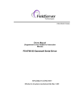
A Sierra Monitor Company
Driver Manual
(Supplement to the FieldServer Instruction Manual)
FS-8700-20 Profibus DP
APPLICABILITY & EFFECTIVITY
Effective for all systems manufactured after May 1, 2001
Driver Version:
1.02
Document Revision: 4
FS-8700-20 Profibus DP Driver Manual
Table of Contents
Table of Contents
1.
Profibus DP Description...................................................................................................3
2.
Driver Scope of Supply.....................................................................................................4
2.1.
Supplied by FieldServer Technologies for this driver ....................................................4
2.2.
Provided by the Supplier of 3rd Party Equipment...........................................................4
2.2.1. Hardware...................................................................................................................4
2.2.2. Software ....................................................................................................................4
3.
3.1.
3.2.
3.3.
3.4.
3.5.
Hardware Connections .....................................................................................................5
Hardware Troubleshooting ............................................................................................5
SST Profibus card LEDs ...............................................................................................5
Profibus Master Configuration.......................................................................................6
Using the SST Configuration Tool for Profibus Master Configuration ...........................6
Using COM PROFIBUS for Profibus Master Configuration...........................................6
4.1.
4.2.
4.3.
4.4.
4.5.
4.6.
Configuring the FieldServer as a Profibus DP Master...................................................7
General..........................................................................................................................7
Data Arrays/ Descriptors ...............................................................................................7
Client Side Connection Descriptions .............................................................................8
Client Side Node Descriptors ........................................................................................8
Client Side Map Descriptors..........................................................................................9
Creating the Network Configuration File for the Master ..............................................10
5.1.
5.2.
5.3.
5.4.
5.5.
Configuring the FieldServer as a Profibus DP Slave Only..........................................13
General........................................................................................................................13
Data Arrays/ Descriptors .............................................................................................13
Server Side Connection Descriptions..........................................................................14
Server Side Node Descriptors.....................................................................................14
Server Side Map Descriptors ......................................................................................15
4.
5.
Appendix A.
Special Driver Parameters ............................................................................16
Appendix A.1.
DP_Buffer ....................................................................................................16
Appendix A.2.
Data_Type, Address & Length ....................................................................16
Appendix B.
Driver Notes ...................................................................................................17
Appendix B.1.
Understanding buffer types and Map Descriptor functions..........................17
Appendix C.
Troubleshooting ............................................................................................19
Appendix C.1.
FieldServer as a Profibus slave...................................................................19
Appendix C.2.
FieldServer as a Profibus Master ................................................................20
Appendix C.3.
Error and Informational Messages on Ruinet E and F screens ...................21
FieldServer Technologies 1991 Tarob Court Milpitas, California 95035 USA Web:www.fieldServer.com
Tel: (408) 262-2299 Fax: (408) 262-9042 Toll_Free: 888-509-1970 email: [email protected]
FS-8700-20 Profibus DP Driver Manual
1.
Page 3 of 22
Profibus DP Description
The Profibus DP driver allows the FieldServer to transfer data to and from devices using
Profibus DP protocol. The Communications Adapter card is included with the FieldServer. The
FieldServer can function as either a Master or a Slave on the Profibus Network.
When acting as a DP Master, the FieldServer requires a Profibus master configuration file in
addition to its own configuration file.
The Profibus master configuration file
(bridge.bss/bridge.2bf) describes the operating network, and the FieldServer configuration file
(config.csv) describes the data that will be accessed within the Profibus slaves. As slaves are
added or removed from the Profibus network, the Profibus master configuration file will need to
be updated. The Profibus master configuration is created using a Profibus configuration tool.
The tool provided on the SST CD can be used to create this file.
As a slave, the Profibus DP driver allows the FieldServer to be a single slave station to another
master. This slave is capable of transferring 244 bytes of input and 244 bytes of output to the
other master. If it is necessary to transfer more data to a Profibus master, then the Profibus
DPMS driver and adapter card will be necessary. For Slave applications, the Profibus master
configuration file is not used, and only the FieldServer configuration file will be used to set the
FieldServer’s Profibus Slave station address and buffer sizes.
To connect to the Profibus network, the FieldServer has been equipped with a 5136-PFB-ISA
card. This card has a standard DB-9 Profibus port that will accommodate a DB9 (Male)
Profibus connector (supplied) and drop cable (not supplied).
The 5136-PFB-ISA card requires firmware (PFBDP.SS1) which will be factory installed onto the
FieldServer prior to shipment.
The information that follows describes how to expand upon the factory defaults provided in the
configuration files included with the FieldServer.
FieldServer Technologies 1991 Tarob Court Milpitas, California 95035 USA Web:www.fieldServer.com
Tel: (408) 262-2299 Fax: (408) 262-9042 Toll_Free: 888-509-1970 email: [email protected]
FS-8700-20 Profibus DP Driver Manual
2.
Page 4 of 22
Driver Scope of Supply
2.1.
Supplied by FieldServer Technologies for this driver
FieldServer Technologies
PART #
SST 5136-PFB-ISA
FS-8700-20
2.2.
Description
Profibus ISA card
SST CD “For Profibus Interface Cards”
Profibus connector without terminating resistor
Driver Manual.
Provided by the Supplier of 3rd Party Equipment
2.2.1.
PART #
2.2.2.
PART #
Hardware
DESCRIPTION
Profibus DP Network Components
PC for configuration tool
Profibus connector with terminating resistor (if required)
Software
DESCRIPTION
User is required to create gsd file if required. Template gsd is
available on the SST CD provided.
FieldServer Technologies 1991 Tarob Court Milpitas, California 95035 USA Web:www.fieldServer.com
Tel: (408) 262-2299 Fax: (408) 262-9042 Toll_Free: 888-509-1970 email: [email protected]
FS-8700-20 Profibus DP Driver Manual
3.
Page 5 of 22
Hardware Connections
The FieldServer is equipped with a SST 5136-PFB-ISA interface card, which has a standard
Profibus DB-9 interface available for connection to the Profibus network. If the FieldServer is
located at an end of the network, termination will be required. For more information on Profibus
cables and connections, please refer to the documentation provided on the SST CD.
WARNING: Improper cabling can cause physical layer problems that are hard to diagnose.
The FieldServer is connected to the Profibus DP as shown in the connection drawing below:
Configure the Profibus DP according to manufacturer’s instructions
SST 5136-PFB ISA card
Comms LED
Sys LED
1
A
FS-X40
Phoenix Connector
2
GND
3
4
B
5
OR
A
8
DB 9 Connector 3
GND
1
B
NOTES
1) Connect only via the Phoenix or DB9
connector to the Profibus network.
2) Terminate DB9 by connecting pin 1-2 and 4-5
on the Phoenix connector
(408)-262-2299
PROFIBUS DP
CONNECTION DIAGRAM
BASE NAME:
FILE NAME:
3.1.
DATE: 03/09/04
BY:
MC
Hardware Troubleshooting
During initialization, the Profibus DP driver checks for the 5136-PFB-ISA hardware and
checks for any conflicts with other hardware. If any errors occur during initialization, an
entry in the error log will be produced.
3.2.
SST Profibus card LEDs
There are two LEDs on the SST Profibus Card. When operating normally the COM LED
should remain solid green. Any communications errors will cause it to flash red for at least
one second. The SYS LED shows the status of both the master and slave. If using either
the slave or master, the SYS LED will show green if all is ok, amber if all is ok but the bus is
running in program mode, and red if there is a problem. If running both master and slave,
the LED will sequence through the master status, the slave status and then off.
FieldServer Technologies 1991 Tarob Court Milpitas, California 95035 USA Web:www.fieldServer.com
Tel: (408) 262-2299 Fax: (408) 262-9042 Toll_Free: 888-509-1970 email: [email protected]
FS-8700-20 Profibus DP Driver Manual
3.3.
Page 6 of 22
Profibus Master Configuration
If using the FieldServer as a Profibus master, provide a configuration file to fully describe the
network connected to the FieldServer. The Profibus driver will accept a 2BF file or a BSS
file. The 2BF file is created using COM PROFIBUS from Siemens. The BSS file is created
using the SST Profibus Configuration tool. These files can be loaded onto the FieldServer
using the FieldServer RUI utilities.
If no configuration file is found on the FieldServer, the Profibus DP driver will still be
available as a slave if the System_Station_Address and local Node ID values match. See
section on configuring as a Slave for more details. After power up, the FieldServer will
continually try to detect the Profibus baud rate. Once detected, the FieldServer will go
online and send its inputs to the master, and receive its outputs from the master. The size
of the input and output buffers are determined by examining the Map Descriptors within the
FieldServer configuration file.
3.4.
Using the SST Configuration Tool for Profibus Master Configuration
To use the SST Configuration tool, install it onto a Windows machine from the CD provided.
After starting the tool:
Create a new network specifying the SST 5163-PFB-ISA as the master.
Set the network properties such as baud rate by right clicking on the PROFIBUS-DP icon.
Add the slaves intended to connect to the network.
When complete, save the network and from the Edit menu, select export binary. Save the
binary file as bridge.bss.
Send bridge.bss to the FieldServer using RUI utilities.
3.5.
Using COM PROFIBUS for Profibus Master Configuration.
Please refer to the COM PROFIBUS manual for instructions on how to create a master
configuration file using COM PROFIBUS. Once completed, save the binary file as bridge.2bf
and send it to the FieldServer using RUI utilities.
FieldServer Technologies 1991 Tarob Court Milpitas, California 95035 USA Web:www.fieldServer.com
Tel: (408) 262-2299 Fax: (408) 262-9042 Toll_Free: 888-509-1970 email: [email protected]
FS-8700-20 Profibus DP Driver Manual
4.
Page 7 of 22
Configuring the FieldServer as a Profibus DP Master
The sections below describe the parameters available for configuring the driver as a Client.
Note that * indicates an optional parameter, with the bold legal value being the default.
4.1.
General
Section Title
FieldServer
Column Title
Title
System_Station_Address
Function
Provide a title for the
configuration file (displays on
RUI editor)
Legal Values
Up to 15 alphanumeric
characters
Profibus DP Master Station ID
0-125
of the FieldServer
Example:
// Common information
FieldServer
Title,
Profibus DP Master,
4.2.
System_Station_Address
0
Data Arrays/ Descriptors
Data Arrays are the neutral data buffers used by the FieldServer to pass data between
communications drivers, and are defined as follows:
Section Title
Data_Arrays
Column Title
Function
Data_Array_Name
Provide name for Data Array
Data_Format
Provides data format
Data_Array_Length
Number of Data Objects
Legal Values
Up to 15 alphanumeric
characters
FLOAT, BIT, UInt16,
SInt16, Packed_Bit,
Byte, Packed_Byte,
Swapped_Byte
1-10,000
Example
// Data Arrays
Data_Arrays
Data_Array_Name,
DA_AI_01,
DA_AO_01,
Data_Format,
UInt16,
UInt16,
Data_Array_Length
200
200
FieldServer Technologies 1991 Tarob Court Milpitas, California 95035 USA Web:www.fieldServer.com
Tel: (408) 262-2299 Fax: (408) 262-9042 Toll_Free: 888-509-1970 email: [email protected]
FS-8700-20 Profibus DP Driver Manual
4.3.
Page 8 of 22
Client Side Connection Descriptions
The adapter used for the Profibus driver must be declared in the connections section.
Section Title
Connections
Column Title
Adapter
Protocol
Function
Adapter Name
Specify protocol used
Legal Values
Prof_DP
Profibus_DP
Example
//
Client Side Connections
Connections
Adapter,
Prof_DP,
4.4.
Protocol
Profibus_DP
Client Side Node Descriptors
For each Profibus slave that the user wishes to access data on, an entry into a node table
must be made. The table associates a name with the node number and connection.
Section Title
Nodes
Column Title
Function
Node_Name
Provide name for node
Node_ID
Station ID of destination Profibus 0-125 ( do not use same ID as in
device
System_Station_Address)
Protocol
Specify protocol used
Adapter
Specify
which
adapter
connected to the FieldServer
Legal Values
Up
to
32
characters
alphanumeric
Profibus_DP
is
Prof_DP
Example
//
Client Side Nodes
Nodes
Node_Name,
PDP_01,
Node_ID,
1,
Protocol,
Profibus_DP,
Adapter
Prof_DP
FieldServer Technologies 1991 Tarob Court Milpitas, California 95035 USA Web:www.fieldServer.com
Tel: (408) 262-2299 Fax: (408) 262-9042 Toll_Free: 888-509-1970 email: [email protected]
FS-8700-20 Profibus DP Driver Manual
4.5.
Page 9 of 22
Client Side Map Descriptors
Map Descriptors control when and how data is transferred to or from the Profibus slaves.
Column Title
Function
Legal Values
Map_Descriptor_Name Name of this Map Descriptor
Up to 32 alphanumeric characters
Name of Data Array where data is to be stored One of the Data Array names from “Data Array”
Data_Array_Name
in the FieldServer
section above
Data_Array_Offset
Starting location in Data Array
0 to maximum specified in “Data Array” section above
Function
Function of Client Map Descriptor
RDBC, WRBC
One of the node names specified in “Client Side
Node_Name
Name of Node to fetch data or write data to
Nodes” above
Data_Type
Data type
FLOAT, WORD, BYTE, BIT
DP_Buffer
Specify buffer in the DP card being accessed.
Input, Output
0-243
Address in DP_Buffer being accessed,
Note: When using Data_Type BIT, the address is in
Address
expressed in byte offset
bit e.g. from 0 - 1951
1- 1952, depending on Data_Type
Number of points in DP_Buffer being accessed,
Length
e.g. when Data Type is WORD and length is 10, it
expressed in points defined by Data_Type
means that 10*2 = 20 bytes are used in the buffer
Example
//
Client Side Map Descriptors
Map_Descriptors
Map_Descriptor_Name,
FLOAT_IN_01,
INT_IN_01,
BYTE_IN_01,
BIT_IN_0,1
Data_Array_Name,
DA_FI_01,
DA_AI_01,
DA_BI_01,
DA_DI_01,
Data_Array_Offset,
0,
0,
0,
0,
Function,
WRBC,
WRBC,
WRBC,
WRBC,
Node_Name,
PDP_01,
PDP_01,
PDP_01,
PDP_01,
DP_Type,
FLOAT,
WORD,
BYTE,
BIT,
DP_Buffer,
Output,
Output,
Output,
Output,
Address,
0000,
0080,
0120,
0140,
Length
20
20
20
32
FLOAT_OUT_01,
INT_OUT_01,
BYTE_IN_01,
BIT_IN_01,
DA_FO_01,
DA_AO_01,
DA_BO_01,
DA_DO_01,
0,
0,
0,
0,
RDBC,
RDBC,
RDBC,
RDBC,
PDP_01,
PDP_01,
PDP_01,
PDP_01,
FLOAT,
WORD,
BYTE,
BIT,
Input,
Input,
Input,
Input,
0000,
0080,
0120,
0140,
20
20
20
32
FieldServer Technologies 1991 Tarob Court Milpitas, California 95035 USA Web:www.fieldServer.com
Tel: (408) 262-2299 Fax: (408) 262-9042 Toll_Free: 888-509-1970 email: [email protected]
FS-8700-20 Profibus DP Driver Manual
4.6.
Page 10 of 22
Creating the Network Configuration File for the Master
The output of this procedure is a bridge.bss file that has to be downloaded to the
FieldServer.
1) Start the SST Profibus Network Configuration Tool and drag the 5136-PFB-ISA MASTER
[Rev 1.3] Master device into the right-hand window pane.
2) Set the Station to be the same as defined under System_Station_Address in the
config.csv file. Click OK to close the Master window.
3) Right-click on the PROFIBUS_DP icon and choose Properties to configure the network.
FieldServer Technologies 1991 Tarob Court Milpitas, California 95035 USA Web:www.fieldServer.com
Tel: (408) 262-2299 Fax: (408) 262-9042 Toll_Free: 888-509-1970 email: [email protected]
FS-8700-20 Profibus DP Driver Manual
Page 11 of 22
4) Set the Baud Rate to a value supported by the Slaves and your cabling media. Choose a
highest Station on the network if you wish to enhance performance, which will prevent the
Master from scanning non-existant Stations. Click OK to complete the network configuration.
5) Drag your Slave devices onto the right window pane and configure them as per
manufacturer’s instructions. Choose a unique Station ID for each Slave.
There has to be Node descriptor with matching Node ID to Station ID for each Slave setup
in the FieldServer’s config.csv file.
Important Note:
All Profibus Masters check for a match in the connection size in bytes to Slaves before
allowing a connection. Make sure you add the appropriate Modules for Input/Output Data to
create a connection size that matches the connection size setup in the Slave device;
otherwise the Master will not connect to the Slave.
FieldServer Technologies 1991 Tarob Court Milpitas, California 95035 USA Web:www.fieldServer.com
Tel: (408) 262-2299 Fax: (408) 262-9042 Toll_Free: 888-509-1970 email: [email protected]
FS-8700-20 Profibus DP Driver Manual
Page 12 of 22
6) Right-click on the PFB_ISA_MASTER Icon and select Export Binary and create a file called
bridge.bss. Download this file to your FieldServer using Ruinet and restart the FieldServer.
FieldServer Technologies 1991 Tarob Court Milpitas, California 95035 USA Web:www.fieldServer.com
Tel: (408) 262-2299 Fax: (408) 262-9042 Toll_Free: 888-509-1970 email: [email protected]
FS-8700-20 Profibus DP Driver Manual
5.
Page 13 of 22
Configuring the FieldServer as a Profibus DP Slave Only
The sections below describe the parameters available for configuring the driver as a Server.
Note that * indicates an optional parameter, with the bold legal value being the default.
5.1.
General
Section Title
FieldServer
Column Title
Title
System_Station_Address
Function
Provide a title for the
configuration file (displays on
RUI editor)
Legal Values
Up to 15 alphanumeric
characters
Profibus DP Slave Station ID of
0-125
the FieldServer
Example:
// Common information
FieldServer
Title,
Profibus DP Slave,
5.2.
System_Station_Address
1
Data Arrays/ Descriptors
Data Arrays are the neutral data buffers used by the FieldServer to pass data between
communications drivers, and are defined as follows:
Section Title
Data_Arrays
Column Title
Function
Data_Array_Name
Provide name for Data Array
Data_Format
Provides data format
Data_Array_Length
Number of Data Objects
Legal Values
Up to 15 alphanumeric
characters
FLOAT, BIT, UInt16,
SInt16, Packed_Bit,
Byte, Packed_Byte,
Swapped_Byte
1-10,000
Example
// Data Arrays
Data_Arrays
Data_Array_Name,
DA_AI_01,
DA_AO_01,
Data_Format,
UInt16,
UInt16,
Data_Array_Length
200
200
FieldServer Technologies 1991 Tarob Court Milpitas, California 95035 USA Web:www.fieldServer.com
Tel: (408) 262-2299 Fax: (408) 262-9042 Toll_Free: 888-509-1970 email: [email protected]
FS-8700-20 Profibus DP Driver Manual
5.3.
Page 14 of 22
Server Side Connection Descriptions
The adapter used for the Profibus driver must be declared in the connections section.
Section Title
Connections
Column Title
Adapter
Protocol
Function
Adapter Name
Specify protocol used
Profibus_DP_Baud
Specifies network baudrate
Legal Values
Prof_DP
Profibus_DP
9600, 19200, 93.75K, 187.5K,
500K, 750K, 1.5M, 3M, 6M,
12M
Example
//
Client Side Connections
Connections
Adapter,
Prof_DP,
5.4.
Protocol,
Profibus_DP,
Profibus_DP_Baud
19200
Server Side Node Descriptors
Section Title
Nodes
Column Title
Function
Node_Name
Provide name for node
Legal Values
Up
to
32
characters
alphanumeric
0-125
Node_ID
Station ID of the Slave
Must be same as Value used for
System_Station_Address
Protocol
Specify protocol used
Profibus_DP
Adapter
Specify
which
adapter
connected to the FieldServer
is
Prof_DP
Example
//
Client Side Nodes
Nodes
Node_Name,
PDP_01,
Node_ID,
1,
Protocol,
Profibus_DP,
Adapter
Prof_DP
FieldServer Technologies 1991 Tarob Court Milpitas, California 95035 USA Web:www.fieldServer.com
Tel: (408) 262-2299 Fax: (408) 262-9042 Toll_Free: 888-509-1970 email: [email protected]
FS-8700-20 Profibus DP Driver Manual
5.5.
Page 15 of 22
Server Side Map Descriptors
Map Descriptors control when and how data is transferred to or from the card buffers for an external Profibus Master to access.
Column Title
Map_Descriptor_Name
Data_Array_Name
Data_Array_Offset
Function
Node_Name
Data_Type
DP_Buffer
Address
Length
Function
Legal Values
Name of this Map Descriptor
Up to 32 alphanumeric characters
Name of Data Array where data is to be stored in One of the Data Array names from “Data Array”
the FieldServer
section above
0 to maximum specified in “Data Array” section
Starting location in Data Array
above
Function of Server Map Descriptor
RDBC, WRBC
The node name specified in “Server Side Nodes”
Name of DP Server Node
above
Data type
FLOAT, WORD, BYTE, BIT
Specify buffer in the DP card being accessed.
Input, Output
0-243
Address in DP_Buffer being accessed,
Note: When using Data_Type BIT, the address is
expressed in byte offset
in bit eg. from 0 - 1951
1- 1952, depending on Data_Type
Number of points in DP_Buffer being accessed,
eg. when Data Type is WORD and length is 10, it
expressed in points defined by Data_Type
means that 10*2 = 20 bytes are used in the buffer
Example
//
Server Side Map Descriptors
Map_Descriptors
Map_Descriptor_Name,
FLOAT_IN_01,
INT_IN_01,
BYTE_IN_01,
BIT_IN_0,1
Data_Array_Name,
DA_FI_01,
DA_AI_01,
DA_BI_01,
DA_DI_01,
Data_Array_Offset,
0,
0,
0,
0,
Function,
RDBC,
RDBC,
RDBC,
RDBC,
Node_Name,
PDP_01,
PDP_01,
PDP_01,
PDP_01,
DP_Type,
FLOAT,
WORD,
BYTE,
BIT,
DP_Buffer,
Output,
Output,
Output,
Output,
Address,
0000,
0080,
0120,
0140,
Length
20
20
20
32
FLOAT_OUT_01,
INT_OUT_01,
BYTE_IN_01,
BIT_IN_01,
DA_FO_01,
DA_AO_01,
DA_BO_01,
DA_DO_01,
0,
0,
0,
0,
WRBC,
WRBC,
WRBC,
WRBC,
PDP_01,
PDP_01,
PDP_01,
PDP_01,
FLOAT,
WORD,
BYTE,
BIT,
Input,
Input,
Input,
Input,
0000,
0080,
0120,
0140,
20
20
20
32
FieldServer Technologies 1991 Tarob Court Milpitas, California 95035 USA Web:www.fieldServer.com
Tel: (408) 262-2299 Fax: (408) 262-9042 Toll_Free: 888-509-1970 email: [email protected]
FS-8700-20 Profibus DP Driver Manual
Page 16 of 22
Appendix A. Special Driver Parameters
Appendix A.1. DP_Buffer
Within the Profibus DP card, the FieldServer can access data from two distinct buffers. The
Input buffer is the data that is sent from the slave to master. The Output buffer is the data
sent from the master to the slave. Each Map Descriptor specifies which one of these buffers
to access in the card.
DP_Buffer
Input
Output
Description
Data to the master from a slave
Data from the master to a slave
Appendix A.2. Data_Type, Address & Length
Each Map Descriptor also specifies the Profibus DP data type. The data arrives from a
Slave or is sent from a Master as a sequence of bytes. By specifying the DP data type, the
driver knows how to interpret the bytes within the buffer. The supported types are Bit, Byte,
Word and Float. To indicate where in the buffer to access the data, the Address field is
used. For Byte, Word and Float type mappings, the address specifies the offset in bytes
from the beginning of the buffer. For Bit type mappings, the address specifies the offset in
bits from the beginning of the buffer. A bit offset of 0 would access the least significant bit in
the first byte in the designated buffer.
Data_Type
Bit
Byte
Word
Float
Description
Transfer Length bits to Data Array
Transfer Length bytes to Data Array
Swap the bytes and transfer Length words to Data Array
Swap the bytes and transfer Length floats to Data Array
FieldServer Technologies 1991 Tarob Court Milpitas, California 95035 USA Web:www.fieldServer.com
Tel: (408) 262-2299 Fax: (408) 262-9042 Toll_Free: 888-509-1970 email: [email protected]
FS-8700-20 Profibus DP Driver Manual
Page 17 of 22
Appendix B. Driver Notes
Appendix B.1. Understanding buffer types and Map Descriptor functions
The following DP_Buffer types and Map Descriptor functions are normally used together
when the FieldServer is used as a DP Master:
DP Master:
DP_Buffer
Output
Input
Function
WRBC
RDBC
The Buffer functions are reversed when using the FieldServer as a DP Slave:
DP Slave:
DP_Buffer
Output
Input
Function
RDBC
WRBC
The diagram below explains the data flows for both buffers when using the FieldServer as a
DP Master:
Note that for the Input buffer, the data is coming from the external DP Slave and is
transferred into the DP Master card’s internal input buffer. The Map Descriptor being of the
RDBC function ( Read Data Block Continuous ) transfers the data from the card buffer into
the FieldServer’s Data Array packing it correctly according to the specified DP_Type.
For the Output buffer, the data is written from the FieldServer’s Data Array by the WRBC
function Map Descriptor ( Write Data Block Continuous ) into the DP Master card’s internal
output buffer from where it is transferred across the Profibus network to the external DP
Slave’s input buffer.
FieldServer Technologies 1991 Tarob Court Milpitas, California 95035 USA Web:www.fieldServer.com
Tel: (408) 262-2299 Fax: (408) 262-9042 Toll_Free: 888-509-1970 email: [email protected]
FS-8700-20 Profibus DP Driver Manual
Page 18 of 22
FieldServer
Data Array
Data Array
DP_Buffer =
Input
DP_Buffer =
Output
RDBC Mapdesc
WRBC Mapdesc
*
*
SST 5136 – PFB - ISA
Card input buffer
0
1
…. 243
Card output buffer
0
1
….
243
Profibus
Network
External DP Slave 01
Card output buffer
0
1
243
….
Card input buffer
0
1
….
243
DP Master
.
.
External DP Slave 126
Card output buffer
0
1
….
243
Card input buffer
The Node ID determines to which external
* Note:
DP slave the data will be sent or fetched from.
0
1
….
243
FieldServer Technologies 1991 Tarob Court Milpitas, California 95035 USA Web:www.fieldServer.com
Tel: (408) 262-2299 Fax: (408) 262-9042 Toll_Free: 888-509-1970 email: [email protected]
FS-8700-20 Profibus DP Driver Manual
Page 19 of 22
Appendix C. Troubleshooting
Appendix C.1. FieldServer as a Profibus slave
If no communications is being experienced between a Profibus Master and a FieldServer
Profibus Slave, check for the following most common issues:
•
•
•
•
•
•
•
•
The baud rate for this driver must be specified in the Connections section of the
configuration.
Baud rate must match the baud rate being used on the network.
The Node_ID must match the System_Station_Address in the configuration - having
these two parameters match in the configuration tells the FieldServer that the buffer
referenced in the Node_ID refers to the buffers in the Profibus card attached to the
FieldServer.
The gse file must match the FieldServer hardware being used
o FieldServer offers several hardware platforms that support Profibus. Each
hardware platform requires it’s own gse file. Make sure that the gse file being
used is the correct file for the hardware platform in use.
o The gse file can be opened with a text editor. The Vendor and model name can
be checked in this file. For the FieldServer X40 Profibus Master/Slave, the
Vendor is “SST”, and the Model Name is “5136-PFB-ISA”. The current revision is
1.9, which uses Hardware revision 1.0 and software release 1.8.
The byte count for the gse profile must match the byte count configured in the
FieldServer
o The gse being used is either going to allow the client(via the network
configuration tool) to select the bytes to be used, or the byte make-up will be
fixed and specified in the gse. Either way, the largest byte offset used by the
client must match the largest byte offset configured in the FieldServer.
o When selecting byte count with a network configuration tool, the total amount of
bytes/words/bits setup per Input/Output buffer in the FieldServer configuration
map descriptors must match those selected in the network config tool otherwise
a connection length mismatch will occur and the connection will not be
established. The Fieldserver shows the connection size it expects on the F
(driver message) screen in the RUI utility in order that this value may be checked
against the network configuration tool.
The FieldServer may have bridge.bss loaded, which will configure it as a master
o The bridge.bss file is loaded by default when FieldServers ship with the default
Profibus Master configuration. This file must not exist in applications where
FieldServer is being used as a slave.
o To check for the file, try uploading the file from the FieldServer using the RUI
Utility. If it uploads successfully, then it will need to be deleted. See the
FieldServer Utilities manual for instructions on how to do this.
The FieldServer may be missing the pfbdp.ss1 file
o This file is compulsory for all SST Profibus applications, and may be missing for
some reason.
o To check for the file, try uploading the file from the FieldServer using the RUI
Utility. If it uploads successfully, then this is not the problem.
The direction of the communications (Input/Output Buffer) may be incorrectly configured.
o Buffer names can be confusing, especially when looking at the Slave. The
buffers are named according to their direction of communication in the Master.
FieldServer Technologies 1991 Tarob Court Milpitas, California 95035 USA Web:www.fieldServer.com
Tel: (408) 262-2299 Fax: (408) 262-9042 Toll_Free: 888-509-1970 email: [email protected]
FS-8700-20 Profibus DP Driver Manual
•
•
•
Page 20 of 22
Hence, an Input buffer in the slave will write data to the master, and data will be
received from the master in the output buffer.
o Remember that as a slave, the FieldServer will have to write data into the input
buffer (function=wrbc), and read data from the output buffer (function=rdbc).
The Profibus card may be faulty.
If this is the case, then there will be an error message in the FieldServer RUI error
screen indicating that the card could not be reached. Check for this message. If it is
there, try opening up the FieldServer and re-seating the card. If this does not help,
contact FieldServer Technical support for jumper settings on the card, and further
possible troubleshooting or return authorization.
The Data Type/Offset/Length combination may be incorrectly set up
o In the FieldServer configuration, the Offset Parameter almost always refers to the
buffer offset in bytes (starting at 0), regardless of data type. The only exception is
the BIT data type which specifies offset in bits to allow for offsets that are not a
multiple of 8. The Length parameter always refers to length in items, which
means Float data will be the number of float values, Word data will be the
number of words, etc.
Appendix C.2. FieldServer as a Profibus Master
The most important aspect of using the FieldServer as a Profibus Master is that the .bss file
must be configured and loaded into the FieldServer as bridge.bss. The SST configuration
tool must be used to configure this file. This tool can be found on the SST CD supplied with
the FieldServer.
As a Master, the FieldServer also needs to have the pfbdp.ss1 file loaded, and care must
also be taken with direction of communication and Data type/length specification. Note that
as a Master, the FieldServer will be writing to Output buffers (function=wrbc) and reading
from input buffers (function=rdbc).
FieldServer Technologies 1991 Tarob Court Milpitas, California 95035 USA Web:www.fieldServer.com
Tel: (408) 262-2299 Fax: (408) 262-9042 Toll_Free: 888-509-1970 email: [email protected]
FS-8700-20 Profibus DP Driver Manual
Page 21 of 22
Appendix C.3. Error and Informational Messages on Ruinet E and F screens
Master Mode not enabled
This message means that the FieldServer is not set up to be a Profibus DP Master. This
indicates that the FieldServer did not find a Master scanner file, (bridge.bss). This message
is normal if you configured the FieldServer to be a DP Slave. See the sections on
configuring the FieldServer as either a DP Master or Slave.
FieldServer Technologies 1991 Tarob Court Milpitas, California 95035 USA Web:www.fieldServer.com
Tel: (408) 262-2299 Fax: (408) 262-9042 Toll_Free: 888-509-1970 email: [email protected]
FS-8700-20 Profibus DP Driver Manual
Page 22 of 22
THIS PAGE INTENTIONALLY LEFT BLANK
FieldServer Technologies 1991 Tarob Court Milpitas, California 95035 USA Web:www.fieldServer.com
Tel: (408) 262-2299 Fax: (408) 262-9042 Toll_Free: 888-509-1970 email: [email protected]