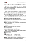
1
.32-.36 AND .46 ASSEMBLY INSTRUCTIONS
ERGO SPECIFICATIONS
Overall Length
46.5"
Tail Rotor Diameter
9.17"
Overall Height
16.38"
Gear Ratio
9.78:1:5.18
Main Rotor Diameter
48.5" (.32-.36)
50" (.46 3D)
Gross Weight
6.75-7.0 lbs.
Heli Division
INTRODUCTION
Congratulations on your purchase of the JR Ergo helicopter kit.
models. For further information, you can contact the AMA at:
This kit has been both engineered and manufactured by JR with help from some
of Japan’s top R/C helicopter engineers (now employed by JR).
Academy of Model Aeronautics
5151 East Memorial Drive
Muncie, IN 47302
(317) 287-1256
As you may well know, the name JR has for years been synonymous with stateof-the-art, high quality radio control systems known the world over for their
exceptional reliability and engineering.
JR now brings this reputation and knowledge into the helicopter market with the
development of the Ergo and the organization of the JR heli division. Years in the
making, the Ergo’s superior quality and exceptional parts fit and finish create a
new standard of quality that was previously unavailable.
PRE-ASSEMBLY INFORMATION
When first opening your Ergo kit, you will notice that all of the parts are
packaged and numbered to coordinate with the assembly step numbers of this
instruction manual.
Before you begin the assembly of your Ergo, we suggest that you first review the
entire instruction manual to become familiar with the assembly sequences and
parts layout.
All small hardware (nuts, bolts, washers, etc.) for each step are separated and
packaged separately within the main parts bags. When beginning a section, you
will need to open only the bag with the corresponding number to the section you
are going to start. It is suggested that you place all of the hardware in an open
container (e.g., coffee can) during assembly so as not to lose any of the small
parts. It may also be helpful to familiarize yourself with the various sizes of
screws, bolts, nuts, etc., as illustrated in the appropriate assembly section before
you begin assembly. At the end of each assembly, in most cases, there should be
no parts remaining.
WARNING
The radio controlled model helicopter contained in this kit is not a toy, but a
sophisticated piece of equipment. This product is not recommended for use by
children. Radio controlled models such as this are capable of causing both
property damage and/or bodily harm to both the operator/assembler and/or
spectator if not properly assembled and operated. Horizon Hobby Distributors
assumes no liability for damage that could occur from the assembly and/or
use/misuse of this product.
Great care has been taken in filling the bags with the correct quantity of parts and
hardware for each section. However, occasionally mistakes do happen. In the
event that you find a parts shortage or are in need of technical assistance, please
contact your local JR heli division parts dealer, or contact the Horizon Service
Center directly.
AMA INFORMATION
We strongly encourage all prospective and current R/C aircraft pilots to join the
Academy of Model Aeronautics. The AMA is a non-profit organization which
provides services to model aircraft pilots. As an AMA member you will receive a
monthly magazine entitled Model Aviation, as well as a liability insurance plan to
cover against possible accident or injury. All AMA charter aircraft clubs require
individuals to hold a current AMA sporting license prior to operation of their
Horizon Service Center
4105 Fieldstone Road
Champaign, IL 61821
(217) 355-9511 (9am to 5pm CST)
2
INDEX
Section
Description
Tools
Page
Section
Description
. . . . . . . . . . . . . . . . . . . . . . . . . . . . . . . . . . . . . . . . . . . . .4-6
5-2
Tail Gear Case Assembly . . . . . . . . . . . . . . . . . . . . . . . . .27
Hardware Identification . . . . . . . . . . . . . . . . . . . . . . . . . . . . . . . . . . . .7
5-3
Tail Center Hub Assembly . . . . . . . . . . . . . . . . . . . . . . . .28
1-1
Clutch Bell/Start Shaft Assembly . . . . . . . . . . . . . . . . . . . .8
5-4
Tail Blade Holder Assembly . . . . . . . . . . . . . . . . . . . . . . .28
1-2
Tail Drive Pinion/Bearing Block Assembly . . . . . . . . . . . .8
5-5
Tail Pitch Control Lever Installation . . . . . . . . . . . . . . . . .29
1-3
Control Ball Installation . . . . . . . . . . . . . . . . . . . . . . . . . . .9
5-6
Tail Fin Attachment . . . . . . . . . . . . . . . . . . . . . . . . . . . . .29
1-4
Servo Mixing Lever Unit Assembly . . . . . . . . . . . . . . . . .9
5-7
Tail Boom Carrier Installation . . . . . . . . . . . . . . . . . . . . .30
1-5
Elevator Arm Assembly . . . . . . . . . . . . . . . . . . . . . . . . . .10
5-8
Tail Boom Assembly Installation . . . . . . . . . . . . . . . . . . .30
1-6
Fuel Tank Assembly . . . . . . . . . . . . . . . . . . . . . . . . . . . . .10
5-9
Tail Boom Brace Assembly . . . . . . . . . . . . . . . . . . . . . . .31
2-1
Upper Main Frame Section Assembly . . . . . . . . . . . . . . .11
5-10
Tail Boom Brace Installation . . . . . . . . . . . . . . . . . . . . . .31
2-2
Upper Main Frame Control Lever Installation . . . . . . . . .12
6-1
Upper Servo Tray Installation . . . . . . . . . . . . . . . . . . . . . .32
2-3
Lower Main Frame Assembly . . . . . . . . . . . . . . . . . . . . .13
6-2
Servo/Switch Harness Installation . . . . . . . . . . . . . . . . . .33
2-4
Fuel Tank Installation . . . . . . . . . . . . . . . . . . . . . . . . . . . .13
6-3
Tail Control Rod Assembly . . . . . . . . . . . . . . . . . . . . . . .34
2-5
Front Radio Bed/Gyro Mounting Plate Installation . . . . .14
6-4
Tail Control Rod Installation . . . . . . . . . . . . . . . . . . . . . .34
2-6
Cooling Fan Shroud Installlation . . . . . . . . . . . . . . . . . . .14
6-5
Gyro/Receiver/Battery Installation . . . . . . . . . . . . . . . . . .35
2-7
Upper/Lower Main Frame Assembly Attachment . . . . . .15
Radio System Preparation . . . . . . . . . . . . . . . . . . . . . . . . . . . . . . . . . .36
3-1
Main Drive Gear/Autorotation Assembly . . . . . . . . . . . . .16
7-1
Aileron Linkages . . . . . . . . . . . . . . . . . . . . . . . . . . . . . . .37
3-2
Main Drive Gear/Autorotation Assembly Installation . . .16
7-2
Elevator Linkage Installation . . . . . . . . . . . . . . . . . . . . . .37
3-3
Landing Gear Assembly Installation . . . . . . . . . . . . . . . .17
7-3
Collective Linkage Installation . . . . . . . . . . . . . . . . . . . . .38
3-4
.32/.36 Cooling Fan/Hub Installation . . . . . . . . . . . . . . . .17
7-4
Tail Control Rod Servo Connection . . . . . . . . . . . . . . . . .38
3-4.1
.46 Cooling Fan Installation . . . . . . . . . . . . . . . . . . . . . . .18
7-5
Throttle Linkage Installation (ALL) . . . . . . . . . . . . . . . . .39
3-5
.32/.36 Engine Mount Attachment . . . . . . . . . . . . . . . . . .18
8-1
Body Assembly/Canopy Attachment . . . . . . . . . . . . . . . .40
3-5.1
.46 Engine Mount Attachment . . . . . . . . . . . . . . . . . . . . .19
8-2
Body Attachment . . . . . . . . . . . . . . . . . . . . . . . . . . . . . . .40
3-6
Clutch Assembly Attachment (ALL) . . . . . . . . . . . . . . . .19
8-3
Main Rotor Blade Balancing . . . . . . . . . . . . . . . . . . . . . .41
3-7
Engine Installation (ALL) . . . . . . . . . . . . . . . . . . . . . . . . .20
8-4
Main Rotor Blade Attachment . . . . . . . . . . . . . . . . . . . . .41
3-8
Installation of the Muffler . . . . . . . . . . . . . . . . . . . . . . . . .20
Servo Adjustment and Radio Set Up . . . . . . . . . . . . . . . . . . . . . . .42-43
4-1
Rotor Head Hub Assembly . . . . . . . . . . . . . . . . . . . . . . . .21
Data Sheets . . . . . . . . . . . . . . . . . . . . . . . . . . . . . . . . . . . . . . . . . .44-49
4-2
Main Blade Holder Assembly . . . . . . . . . . . . . . . . . . . . . .21
Final Pre-Flight Check . . . . . . . . . . . . . . . . . . . . . . . . . . . . . . . . . . . .50
4-3
Main Blade Holder/Seesaw Attachment . . . . . . . . . . . . . .22
General Maintenance . . . . . . . . . . . . . . . . . . . . . . . . . . . . . . . . . . . . .51
4-4
Seesaw Mixing Arm Installation . . . . . . . . . . . . . . . . . . .22
Rotor Head/Swashplate/Washout Assembly Parts List . . . . . . . . .52-53
4-5
Swashplate/Washout Assembly Installation . . . . . . . . . . .23
Start Shaft/Clutch/Engine Assembly Parts List . . . . . . . . . . . . . . .54-55
4-6
Rotor Head Installation . . . . . . . . . . . . . . . . . . . . . . . . . . .24
Cyclic Mixing Arms/Elevator/Aileron Control Arms Parts List . .56-57
4-7
Flybar Installation . . . . . . . . . . . . . . . . . . . . . . . . . . . . . . .25
Upper Main Frame/Radio Tray/Body Set Parts List . . . . . . . . . . .58-59
4-8
Flybar Paddle Attachment . . . . . . . . . . . . . . . . . . . . . . . . .25
Lower Main Frame/Landing Gear/Fuel Tank Parts List . . . . . . . .60-61
4-9
Rotor Head/Swashplate Control Rod Installation . . . . . . .26
Tail Boom/Tail Brace/Tail Boom Carrier Parts List . . . . . . . . . . .62-63
5-1
Tail Output Shaft/Pulley Assembly . . . . . . . . . . . . . . . . . .27
Tail Case/Tail Blade Holders/Tail Pitch Plate Parts List . . . . . . . .64-65
3
Page
ERGO .32-.36 AND ERGO .46 3D FEATURES
Heavy-Duty Aluminum Quad Frame System
Provides excellent rigidity and vibration absorption.
Straight Blade Axle Rotor Head Design
Provides high responsiveness and solid blade tracking.
One-Way Hex Start Shaft System
Provides positive starting. Starter shaft utilizes a one-way bearing
that allows the shaft to stop after the engine is started.
Low Drag Flybar Paddles
Provide quick yet smooth cyclic response at all flight speeds.
Wide Spread Tail Output Shaft Bearings
Reduces vibration and improves control response.
Heavy-Duty Main Blade Grips With 4mm Blade Bolts
Provide a solid and secure mounting surface to easily handle
the stresses of radical 3D flight.
Belt-Driven Tail Rotor Design
Provides easy adjustment and low maintenance. Also eliminates
the need for optional/expensive tube drive shafts.
Rearward Facing Engine Design
Provides easy access to the glow plug for starting. Engine slips
easily through the main frame for trouble-free engine maintenance.
Precision Ball Bearings at All Critical Locations
Provide low wear, high precision and reduced maintenance.
Heavy-Duty Tail Boom Carrier
Provides increased structural rigidity and improved tail rotor precision.
Unique Cyclic Mixing Control System
Offers easy adjustment and precise control.
Pre-Finished Main Rotor Blades (.30 Kit)
Provide easy assembly with excellent flight characteristics.
Self-Aligning One-Piece Steel Clutch System
Offers easy installation and adjustment with exceptional reliability.
Superior Parts Fit and Finish
Make assembly trouble free and enjoyable.
Pre-Assembled Control Linkages
High quality JR ball links are installed and pre-adjusted to take
the guesswork out of assembly while saving building time.
ITEMS REQUIRED TO COMPLETE THE JR ERGO (not supplied in kit)
1. RADIO SYSTEM REQUIREMENTS (NOT INCLUDED):
6-channel or greater R/C helicopter system with 5 servos, 1000 mAh receiver battery and gyro.
4
2. ENGINE REQUIREMENTS (NOT INCLUDED):
A .32-.36 R/C Helicopter Engine (Ergo .30) or .46 R/C Helicopter Engine (Ergo .46)
A special helicopter type muffler is also required
(JRP960078 Ergo .32-.36 Muffler Shown)
(Webra .33 Heli Engine Shown)
(Thunder Tiger Pro .46 Heli Engine Shown)
(JRP960079 Ergo .46 Muffler Shown)
3. BUILDING SUPPLIES (NOT INCLUDED):
The following items are needed to complete the assembly of the JR Ergo:
Fuel Filter
Glow Plugs
Silicone Fuel Tubing
Whip Antenna
Double Sided Servo
Mounting Tape
Locktite 242 or
equivalent
Spiral Tubing
Nylon Wire Ties To
Secure Radio Wires
5
4. TOOLS NEEDED TO ASSEMBLE THE JR ERGO (NOT INCLUDED):
Nut Drivers: 5mm, 7mm
Phillips Screwdirver
Drill and Drill Bits
Needle Nose Pliers
Scissors
Metric Ruler
X-Acto Knife
Small Hammer
Blade Balancer
Allen Wrenches: 1.5, 2.0, 2.5,
3.0mm
5. FIELD EQUIPMENT REQUIRED (NOT INCLUDED):
12 Volt Starting Battery
12 Volt Electric Starter
Helicopter Fuel 15% - 30%
Pitch Gauge
1.5 Volt Glow Plug Battery
Fuel Pump
Ball Link Pliers
6
Remote Glow Plug Adaptor
Hex Starting Shaft
Training Gear (Beginners Only)
HARDWARE IDENTIFICATION
There are many various sizes and shapes of hardware included in this kit.
Prior to assembly, please be careful to identify each screw by matching it to the
full size screw outlines included in each step.
C
A
C
A
B
Self Tapping Screw
3mm
Flat Washer
B
2.6x10mm
A
A
Socket Head Bolt
B
B
C
Socket Head Bolt
A
B
C
A
Set Screw
2x8mm
A
B
Flat Head Screw
3mm
Lock Nut
B
C
Set Screw
A
B
A B
3mm
Spring Washer
3x8mm
A
B
Flat Head Screw
C
Flat Head Cap Screw
A
.05mm
B
C
Spring Washer
A
B
2mm
Hex Nut
Flat Head Cap Screw
A
B
B
Flat Washer
C
B
B
C
B
Tapping Screw
A
4x4mm
.05mm
A
C
A
B
3x8mm
A
A
All of the hardware, screws, nuts, etc., contained in the Ergo kit are described in
the following A, B, C manner:
Hex Nut
7
Lock Nut
1-1
CLUTCH BELL/START SHAFT ASSEMBLY
Starter Hex Adaptor
..........1 pc
Complete Assembly
3x4mm Set Screw
Use Threadlock
* When installing the Start Shaft
Bearing Block Assembly, be sure
the Bearing Block is positioned so
the Bushing faces upward toward
the starter hex adaptor, with the
bearing toward the Clutchbell
Assembly.
3x4mm Set Screw
Start Shaft
*Start Shaft Bearing Block
Clutch Bell Assembly
1-2
Note: Be sure to allow a slight amount of
clearance between the Start Hex
Adaptor and the Bearing Block to
prevent binding.
TAIL DRIVE PINION/BEARING BLOCK ASSEMBLY
Install the Upper Bearing Block so that
the bearing is toward the top:
UP
Bearing
Use Threadlock
...1 pc
3x6mm Socket Head Bolt
3x6mm Socket Head Bolt
3mm Flat Washer
.........1 pc
Front Tail Belt Pulley
(Install Flat Side Up)
3mm Flat Washer
Tail Drive Pinion
Bearing Blocks
Complete Assembly
Tail Drive Pinion
with Shaft
Install the Lower Bearing Block so the
bearing face is toward the bottom:
8
UP
Bearing
1-3
CONTROL BALL INSTALLATION
Mixing Lever (3 pc)
(Prepare 3 Sets)
2x8mm Flat Head Screw
Use Threadlock
........1 pc
2x8mm Flat Head Screw
2mm Nut
Roll Bell Crank
........8 pc
Steel Joint Ball
2x10mm Flat Head Screw
2mm Nut
Steel Joint Ball
........9 pc
Steel Joint Ball
........3 pc
2mm Nut
2x10mm Flat
Head Screw (8 pc)
Mixing Base Arm
(Collective)
Joint Ball (9 pc)
1-4
2x10mm Flat
Head Screw
SERVO MIXING LEVER UNIT ASSEMBLY
Complete Assembly
........2 pc
Use Threadlock
........1 pc
3x8mm Socket
Head Bolt
3x8mm Flat Head Screw
Nylon Washers
3x8mm Socket Head Bolt
....1 pc
3x28mm Socket Head Bolt
........5 pc
Mixing Lever Bushing B
Nylon Washers
Nylon Washers
........1 pc
Mixing Lever Bushing A
3mm Flat Washer
........1 pc
3x8mm Flat Head Screw
Mixing Lever Spacer
........1 pc
Mixing Lever Bushing A
Mixing Lever Bushing B
Mixing
Lever
Spacer
Mixing Base Cross Member
Mixing Base Arm (Roll)
......1 pc
Mixing Base Cross Member
....1 pc
After assembly, any additional play or
movement in the Mixing Lever Unit can
be reduced by adding additional Nylon
Washers as needed.
9
Nylon
Washer
3x8mm Flat Head Screw
3mm Flat
Washer
3x28mm Socket Head Bolt
1-5
ELEVATOR ARM ASSEMBLY
Elevator Arm Rear
Elevator Arm Front
..........2pc
Swashplate A
Arms
2x8mm Flat Head Screw
......2pc
Steel Joint Ball
Elevator Arm Pin
......2pc
Steel Joint Ball
Steel Joint Ball
2x8mm Flat Head Screw
2x8mm Flat
Head Screw
Elevator Arm Pin
Caution: Be sure to note correct Swashplate A Arm installation direction.
Swashplate A
Arm
Swashplate A
Arm
Elevator Arm
Swashplate A Arm
Elevator Arm (Rear)
Elevator Arm (Front)
1-6
Tap-in gently with
a small hammer.
Marked Side In
Marked Side Out
Edge of Work Bench
FUEL TANK ASSEMBLY
Silicone Fuel Tubing
(not included)
Connects to Muffler Pressure Tap
Fuel Tank Clunk
* Silicone Tube (Small)
Tank Grommet
Fuel Tank
Nipple
Silicone Fuel Tubing
(not incuded)
Connects to Engine Carburetor
* Trim before installation to a length of 58mm
10
After assembly, check to be sure the
Fuel Tank Clunk can move from the
bottom to the top of the tank without
touching the back wall of the Fuel Tank.
2-1
UPPER MAIN FRAME SECTION ASSEMBLY
Upper Main Shaft Bearing Block
Use Threadlock On
All Screws
Bearing Flush
with Flange
UP
..........21 pc
Bearing
3x8mm Socket Head Bolt
Position so the side
of the bearing block
that has the bearing
flush with the flange
is upward.
Lower Main Shaft Bearing Block
..........1 pc
3x10mm Socket Head Bolt
UP
Bearing Flush
with Flange
..........11 pc
Bearing
3mm Flat Washer
Position so side of
the bearing block
that has the bearing
flush with the flange
is downward.
Tail Control
Rod Guide
Body Mounting Standoffs Shaft
.......2 pc
3x10mm Socket Head Bolt
Body Mounting Standoff: Short
..........4 pc
2.6x8mm Self Tapping Screw
Bearing side must face upward*
Note: Both the Clutch Bell/Start Shaft Assembly
(Step 1-1) and the Tail Drive Pinion/
Bearing Block Assembly (Step 1-2) are
temporarily installed at this time. These
assemblies will be adjusted and secured
in Step 3-2.
Note: Be sure to use the two shorter Body
Mount Standoffs for this installation.
2.6x8mm Self Tapping
Screw (4pc)
Body Mounting
Standoff: Short
*Bearing side must
face downward
Upper Main Frame
3mm Flat Washer
(11 pc)
3x8mm Socket Head Bolt
(21 pc)
Servo Mounting Plates
11
2-2
UPPER MAIN FRAME CONTROL LEVER INSTALLATION
Use Threadlock
Note: Be sure to install the Elevator
Arm Units in their proper
location as there is a “Front”
and a “Rear” Unit (Step 1-5).
Elevator Arm Bushing
Nylon Washer
Nylon Washer
Elevator Arm Bushing
3x8mm Socket Head Bolt
Nylon Washer
3x6mm Socket Head Bolt
3x8mm Socket
Head Bolt
Nylon Washer
Roll Bellcrank
Spacer
3x22mm Socket
Head Bolt
Mixing Base Nut
........2 pc
3x6mm Socket Head Bolt
3x6mm Socket
Head Bolt
........4 pc
3x8mm Socket Head Bolt
3x22mm Socket Head Bolt
......1 pc
Washout Arm
Bushing
Attach the pre-finished Control Rods to the
Mixing Levers/Control Arms as shown:
A
........1 pc
B
3mm Lock Nut
........5 pc
Nylon Washers
........1 pc
3mm Flat Washer
........1 pc
C
Roll Bellcrank Spacer
........1 pc
Washout Arm Bushing
Pre-Adjusted Length
Elevator Arm Bushing
........2 pc
Mixing Base Nut
........2 pc
3mm Flat Washer
A
B
C
Rod Length
110mm
45mm
75mm
Pre-Adjusted Length
92mm
24mm
59mm
12
Top View
2-3
LOWER MAIN FRAME ASSEMBLY
Lower Main Frame
2.6x8mm Self Tapping Screw (4 pc)
........ 4pc
3x8mm Socket Head Bolt
........4 pc
3mm Lock Nut
........4 pc
3mm Lock Nut
(4 pc)
2.6x8mm Self Tapping Screw
Lower Frame Angle (2 pc)
2.6x8mm Self Tapping Screw
Servo Mounting Plate
3x8mm Socket Head Bolt (4 pc)
2-4
FUEL TANK INSTALLATION
Note: Install the Fuel Tank and Tank Mounting Rubber into the lower frame halves before
attaching the Main Frame Standoffs.
Use Threadlock
Main Frame Standoff, 60mm
When securing Standoffs to frame, position the bottoms of the level surface to
prevent twisting during tightening.
Main Frame
Standoff, 60mm
Tank Mounting
Lower Main Frame
3x8mm Socket
Head Bolt
........2 pc
3x8mm Socket Head Bolt
........4 pc
3x10mm Socket Head Bolt
3x10mm Socket
Head Bolt (4 pc)
Fuel Tank
Main Frame Standoff,
60mm
3x8mm Socket Head Bolt
Main Frame Standoff, 60mm ........ 3 pc
13
Tank Mounting
2-5
FRONT RADIO BED/GYRO MOUNTING PLATE INSTALLATION
Gyro Mounting Plate
........6 pc
Use Threadlock
3x10mm Socket Head Bolt
Front Radio Bed
........2 pc
3x18mm Set Screw
Body Mounting Standoff Long
........2 pc
Body Mounting
Standoff Long
3x10mm Socket
Head Bolt (6 pc)
3x18mm Set Screw (2 pc)
Body Mount Standoff, Long
3x10mm Socket
Head Bolt
2-6
COOLING FAN SHROUD INSTALLATION
Cooling Fan Shroud
........4 pc
2.6x8mm Self Tapping Screw
Ergo .46 Fan Shroud Adjustment
2.6x8mm Self
Tapping Screw
When installing a .46 size engine it
will be necessary to trim the bottom
portion of the Fan Shroud as shown:
1 7/8"
3/4"
2.6x8mm Self Tapping Screw
Remove
14
2-7
3x22mm Socket Head Bolt
UPPER/LOWER MAIN FRAME ASSEMBLY ATTACHMENT
........12 pc
Main Frame Standoff, 32mm
........6 pc
Main Frame Spacer, 12.5mm
........12 pc
Use Threadlock On
All Screws
Main Frame Spacer, 12.5mm
(12 pc)
Main Frame Standoff, 32mm (6 pc)
3x22mm Socket
Head Bolt (12 pc)
3x22mm Socket Head Bolt
15
3-1
MAIN DRIVE GEAR/AUTOROTATION ASSEMBLY
3x6mm Socket Head Bolt (4 pc)
[Tighten equally to prevent
warping of Main Drive Gear]
Use Threadlock
Main Drive Gear
.......4 pc
3x6mm Socket Head Bolt
Autorotaion Assembly
3-2
MAIN DRIVE GEAR/AUTOROTATION ASSEMBLY INSTALLATION
Main Shaft Collar
Use Threadlock
4x4mm Set Screw (4 pc)
8mm
........4 pc
4x4mm Set Screw
Main Rotor Shaft
3x22mm Socket Head Bolt
......1 pc
........1 pc
3mm Lock Nut
3mm
Autorotation Hub
3mm Lock Nut
1.
Secure the Autorotation Hub to the Main Rotor Shaft using
the 3x22mm Socket Head Bolt. Next, slide the Main Shaft
Collar onto the Main Rotor Shaft. While pulling upward on
the Main Rotor Shaft, secure the Main Shaft Collar to the
Main Rotor Shaft using the four 4x4mm Set Screws.
3x22mm Socket Head Bolt
2.
Once the Main Shaft Assembly is in place, adjust the gear mesh of the Clutch Bell
and Tail Belt Pinion Gears, and secure the bolts left loose from Step 2-1.
16
3-3
LANDING GEAR ASSEMBLY INSTALLATION
3x12mm Socket Head Bolt (4 pc)
........4 pc
4x4mm Set Screw
........4 pc
3x12mm Socket Head Bolt
........4 pc
3mm Flat Washer
3mm Flat Washer (4 pc)
........4 pc
Landing Gear Dampers (4 pc)
3mm Lock Nut
3mm Lock
Nut (4 pc)
Landing Strut
4x4mm Set Screw (4 pc)
Antenna Tube
Landing Skid Cap
Landing Skid
20mm
3-4
.32-.36 CO0LING FAN/HUB INSTALLATION
Nut Supplied with Engine
For proper installation of the fan assembly, it is neccessary for
the engine to have the prop drive washer installed.
3x5mm Socket
Head Bolt (4 pc)
Note: If you are building the Ergo .46 3D Version,
proceed to Step 3-4.1
O.S. .32SX-H Installation
Cooling Fan .32-.36
Prop drive washer must be
used for correct installation
For proper installation of this engine, it will be
necessary to purchase the O.S. Prop Drive
Washer for this engine (Part #23408000).
*It is recommended that a Piston Locking Tool
be used to properly secure the Fan Assembly to
the engine.
Cooling Fan Hub .32-.36
Use Threadlock
........4 pc
* Revolution 1003 Piston Locking Tool
(Purchased Separately)
3x5mm Socket Head Bolt
17
3-4.1
.46 COOLING FAN INSTALLATION
Nut Supplied with Engine
Note: If you are building the Ergo .32-.36 Version, proceed to Step 3-5.
Note: It will not be necessary to use the four 3x5mm
Socket Head Bolts included in this screw bag.
Note: It will be necessary to shorten the Crankshaft of
the engine to allow clearance. Test fit the Fan
Assembly to determine the correct amount to be
removed. On the Thunder Tiger Pro .46 Heli
Engine, it will be necessary to remove 1/2" from
the tip of the Crankshaft.
Aluminum Cooling Fan
(Ergo .46)
*It is recommended that a Piston Locking Tool be used to
properly secure the Cooling Fan Assembly to the engine.
* Revolution 1003 Piston Locking Too
(Purchased Separately)
Use Threadlock
3-5
.32-.36 ENGINE MOUNT ATTACHMENT
Note: If you are building the Ergo .46 3D Version proceed to Step 3-5.1.
Engine Mount .32-.36
Use Threadlock
......4 pc
3x15mm Socket Head Bolt
3mm Serrated
Washer (4 pc)
........4 pc
3mm Flat Washer
........4 pc
3mm Serrated Washer
Motor Mount Direction
Top
Shorter Distance
Longer Distance
Bottom
3mm Flat
Washer (4 pc)
It is important to note the proper direction that the motor mount
is installed to achieve the correct alignment of the engine.
18
3x15mm Socket
Head Bolt
3-5.1
.46 ENGINE MOUNT ATTACHMENT
Engine Mount .46
Fan Assembly: .46
Use Threadlock
........4 pc
3mm Serrated
Washer (4 pc)
3x15mm Socket Head Bolt
........4 pc
3mm Flat Washer
........4 pc
3mm Serrated Washer
Motor Mount Direction:
O.S.
Motor Mount Direction:
Thunder Tiger
Top
Top
Longer Distance
Longer Distance
O.S. .46 FS
R-H
Thunder Tiger
Pro .46
Shorter Distance
3mm Flat
Washer (4 pc)
Shorter Distance
3x15mm Socket
Head Bolts (4 pc)
Bottom
Bottom
It is important to note the proper direction that the Motor Mount
is installed to achieve the correct alignment of the engine.
3-6
CLUTCH ASSEMBLY ATTACHMENT (ALL)
2mm Hex Nut
Clutch Assembly
Use Threadlock
........1 pc
*see note
2x8mm Flat Head Screw
3mm Flat Washer
(2 pc)
Steel Joint Ball
........2 pc
2x8mm Flat
Head Screw
3x5mm Socket Head Bolt
........1 pc
2mm Hex Nut
........2 pc
3mm Flat Washer
*Note:
........1 pc
Steel Joint Ball
When installing the Thunder Tiger Pro .46
Heli Engine, it will be necessary to replace
the Standard Throttle Arm with the Long
Offset Arm supplied with the engine.
19
3x5mm Socket Head Bolt
(2 pc)
3-7
ENGINE INSTALLATION (ALL)
........4 pc
3x10mm Socket Head Bolt
........4 pc
3mm Flat Washer
3mm Flat Washer (4 pc)
3x10mm Socket Head Bolt (4 pc)
Correct
Incorrect
Adjust the height and position of the Engine
as shown so the bottom of the Clutch
Assembly is flush with the bottom of the
Clutch Bell. Also check to insure that the
Engine and Clutch Bell are parallel.
3-8
INSTALLATION OF THE MUFFLER
........1 pc
Pressure Tap
3x30mm Socket Head Bolt
*It is highly recommended that you insert
the Muffler Bolts into the Engine Case prior
to installing the engine in the frame.
Note: The installation shown is for a .32-.36 size
engine with the JR muffler (JRP960078).
Installation of other .32-.36/.46 engine
muffler combinations may vary. Please refer
to your engine/muffler instructions for proper
installation.
.......2 pc
Pressure Fuel Line Attachment
Use Threadlock
Pressure Tap
3x30mm Socket Head Bolts
(*Inserted in Step 3-7)
JR .32-.36 Muffler Shown
(Purchased Separately, JRP960078)
20
4-1
ROTOR HEAD HUB ASSEMBLY
3x6mm Socket Head Bolt
Use Threadlock
Head Button
........1 pc
3x6mm Socket Head Bolt
......2 pc
3x8mm Socket Head Bolt
3x8mm Socket Head Bolt
(2 pc)
Phase Adjustment Ring
(insert onto base of Main Rotor Hub)
4-2
Main Rotor Hub
MAIN BLADE HOLDER ASSEMBLY
Steel Joint Ball
Two Sets Required
Main Blade Holder
........4 pc
3x6mm Self Tapping Screw
........2 pc
Main Blade Holder Bearing
2x10mm Flat Head Screw
........2 pc
Steel Joint Ball
Main Blade Holder Bearing
........4 pc
2x10mm Flat Head Screw
Main Blade Holder Bearing
........2 pc
Outer Main Blade Bearing Spacer
Outer Main Blade Bearing Spacer
Inner Main Blade Bearing Spacer
........2 pc
Inner Main Blade Bearing Spacer
3x6mm Self Tapping Screw
21
4-3
MAIN BLADE HOLDER/SEESAW ATTACHMENT
........2 pc
3x5mm Button Head Bolt
Blade Spindle Shaft
........2 pc
4mm Lock Nut
........2 pc
Damper Rubber (2 pc)
Seesaw Spacer (Steel)
........2 pc
Blade Holder Spacer
(Bevel Inward) (2 pc)
Seesaw Spacer (Steel)
(2 pc)
Blade Holder Spacer A
Use Threadlock
4mm Lock Nut (2 pc)
Seesaw Shaft
3x5mm Button Head Bolt
(2 pc)
4-4
SEESAW MIXING ARM INSTALLATION
Use Threadlock
Two Sets Required
........2 pc
3x16mm Socket Head Bolt
........4 pc
2x10mm Flat Head Screw
........6 pc
3mm Flat Washer
........4 pc
Nylon Washer
3mm Flat Washers
........2 pc
3x16mm Socket Head Bolt
Nylon Washer
2x10mm Flat Head Screw
(2 pc)
Nylon Washer
........4 pc
Steel Joint Ball
3mm Flat Washer
Steel Joint Ball
3x16mm Socket
Head Bolt
Seesaw Mixing Arm
Mixing Arm Bushing
22
4-5
SWASHPLATE/WASHOUT ASSEMBLY INSTALLATION
*Washout Assembly
Swashplate Assembly
Upper Swashplate Ring
Connect the two Washout Links
to the correct upper Swashplate
Balls as shown.
Complete Assembly
*SWASHOUT ASSEMBLY INSTALLATION
When installing the washout assembly be sure
the long flange of the mixing base is positioned
downward (toward the swashplate) with the short
portion facing upward.
Washout Assembly
UP
Long portion of mixing base
flange must face downward.
23
4-6
ROTOR HEAD INSTALLATION
........1 pc
3x18mm Socket Head Bolt
Completed Rotor
Head Assembly
........1 pc
3mm Lock Nut
3mm Lock Nut
3x18mm Socket Head Bolt
Rotor Hub Pin
Washout Base
Note:
24
Be sure to engage thePhase
Adjusting Ring into the Washout
Base Groove before securing the
Rotor Head Assembly in place.
4-7
FLYBAR INSTALLATION
Flybar Control Arm (2 pc)
Use Threadlock
4x4mm Set Screw
(2 pc)
*Flybar Bushings (2 pc)
........2 pc
4x4mm Set Screw
* Be sure to insert Flybar Bushings into
the Seesaw Shaft before inserting Flybar.
Flybar
Flybar Centering
Note:
Center the Flybar in the Seesaw Shaft before securing the two Flybar Control Arms.
Check to insure that the two Flybar
Control Arms are parallel to the
center line of the Flybar.
4-8
Center Line
FLYBAR PADDLE ATTACHMENT
........2 pc
3mm Lock Nut
Note proper direction of each Flybar Paddle
(short portion forward, clockwise rotation).
Thread each Flybar Paddle onto the Flybar until the
threaded tip of the Flybar protrudes approximately 4mm.
Adjust each Flybar Paddle so they are parallel to the
Flybar Control Arms, and to each other. Secure to the
Flybar using two 3mm Lock Nuts.
Flybar Paddle (2 pc)
3mm Lock Nut (2 pc)
25
4-9
ROTOR HEAD/SWASHPLATE CONTROL ROD INSTALLATION
*Double Link A (2 pc)
(Washout Arm to
Main Blade Holder)
1
3
2
Pre-Assembled Control Rod Identification:
1
Washout Arm to Flybar Control Arm
(1 Piece Double Link)
x2
47mm
Note:
2
Ergo .46 3D Kit
Your Ergo .46 3D Kit includes an additional set of
Double Links (B Style #960081). These links are
designed to provide proper blade pitch for 3D
Flight (+10° thru -10°).
Swashplate to Roll Bellcrank
(2.3mmx30mm Threaded Rod)
x1
11mm
Using the Standard Double Link “A” will provide a
Standard Blade Pitch Range (+15 thru -4).
3
Standard Double Links “A” are recommended for
all training and sport flying applications.
Swashplate to Washout Arm
(2.3mmx40mm Threaded Rod)
x2
19mm
26
5-1
TAIL OUTPUT SHAFT/PULLEY ASSEMBLY
Complete Assembly
........1 pc
Spring Pin
Tail Output Shaft
Spring Pin
Hammer
Short Distance
Note correct direction of Tail
Output Shaft during assembly.
5-2
Long Distance
Edge of Work Bench
Tail Case Pulley
TAIL GEAR CASE ASSEMBLY
3x12mm Self
Tapping Screw
3x12mm Self
Tapping Screw
Tail Gear Case (L/R)
Tail Output
Shaft Bearing
Tail Output
Shaft Bearing
2.6x12mm Socket
Head Bolt (4 pc)
Tail Drive Belt
Use Threadlock
Tail Boom
........3 pc
3x12mm Self Tapping Screw
........4 pc
2.6x12mm Socket Head Bolt
........4 pc
2.6mm Hex Nut
Tail Boom
Note:
........2 pc
Tail Output Shaft Bearing
2.6mm Hex Nut
(4 pc)
Be sure to position the
Tail Gear Case onto
the shorter slotted side
of the Tail Boom.
Longer (Helicopter)
27
Shorter (Tail Gear Case)
5-3
TAIL CENTER HUB ASSEMBLY
* Be certain to apply Locktite to the two
3x3mm set screws and attach securely to
the tail output shaft so the set screws
engage into the tail output shaft hole.
Failure to secure this assembly properly
can result in tail rotor failure during flight.
3x3mm Set Screw (2pc)
*
Tail Center Hub
Tail Blade Holder Bearing
(4pc)
Tail Output Shaft Hole
Tail Slide Ring Assembly
*
Use Threadlock
3mm Lock Nut
(2 pc)
.......2 pc
3x3mm Set Screw
........2 pc
3mm Lock Nut
........4 pc
Tail Blade Holder Bearing
5-4
TAIL BLADE HOLDER ASSEMBLY
2x8mm Socket
Head Bolt
Tail Blade Holder w/Ball
(Outside)
3x15mm Socket
Head Bolt
Use Threadlock
Rotation
Two Sets Required
........4 pc
2x8mm Socket Head Bolt
Tail Blade Holder
w/o Ball (Inside)
.......2 pc
3x15mm Socket Head Bolt
........4 pc
2mm Hex Nut
........2 pc
3mm Lock Nut
2mm Hex Nut
Rotation
Tail Rotor Blade
3mm Lock Nut
* Be sure to note direction of Tail Rotor Blades during assembly.
28
5-5
TAIL PITCH CONTROL LEVER INSTALLATION
........1 pc
2x8 Flat Head Screw
.......1 pc
2x20mm Socket Head Bolt
........1 pc
2mm Flat Washer
........1 pc
Steel Joint Ball
........1 pc
Tail Lever Bushing
Snap
Onto
Ball
Tail Pitch Control Lever
2mm Flat Washer
Tail Lever Bushing
2x20mm Socket Head Bolt
5-6
Steel Joint Ball
2x8mm Flat
Head Screw
TAIL FIN ATTACHMENT
Vertical Fin
3x10mm Socket Head Bolt
........2 pc
3x8mm Socket Head Bolt
........1 pc
3x10mm Socket Head Bolt
........2 pc
3x12mm Socket Head Bolt
Horizontal Fin
........3 pc
3x12mm Self Tapping Screw
........4 pc
3mm Lock Nut
* Do not completly secure these
bolts as this assembly will need to be
correctly positioned in Step 5-10.
3x12mm Self Tapping
Screw (3 pc)
3mm Lock Nut (4 pc)
* Note: Please attach the Tail Boom
Decal Stripe (located on the decal
sheet) prior to attaching the horizontal
fin/brace clamp.
Horizontal Fin/Brace Clamp (L&R)
*3x12mm Socket Head Bolt (2 pc)
* Tail Boom Decal Stripe
29
*3x8mm Socket Head Bolt (2 pc)
5-7
TAIL BOOM CARRIER INSTALLATION
3mm Lock Nut
Tail Boom Carrier (L&R)
........4 pc
3x15mm Socket Head Bolt
3mm Lock Nut
........2 pc
3x40mm Socket Head Bolt
........6 pc
3mm Lock Nut
* Do not fully tighten at this time. These bolts will
be secured in Step 5-10.
*3x15mm Socket Head Bolt
*3x40mm Socket Head Bolt
5-8
TAIL BOOM ASSEMBLY INSTALLATION
Slide the Tail Boom through the Tail Boom Carrier and
engage the Tail Drive Belt over the Front Pulley. Be
certain to note the correct rotation (direction shown
below. Set the belt tension per the directions below.).
Note:
Secure Bolts completly
after inserting Tail Boom
making sure that the
Tail Output Shaft is
exactly 90° to the
Main Rotor Shaft.
It may be necessary to add one thickness
of electrical tape around the end of the Tail
Boom to insure positive attachment to the
Tail Boom Carrier.
Tail Output
Shaft Pulley
Belt tension should be set so when pressing with your
finger, both sides of the belt do NOT come in contact
with each other. Be sure not to set the belt too tight,
as this can cause vibration and a loss of power.
Rotate the Tail Drive Belt in the direction shown before
installing it onto the front pulley. It is extremely
important to install the belt in the proper direction to
insure correct rotation of the Tail Rotor Blades.
Front Pulley
30
5-9
TAIL BOOM BRACE ASSEMBLY
Tail Brace Connector
........1 pc
2.6x12mm Socket Head Bolt
2.6x15mm Socket Head Bolt
......1 pc
2.6x15mm Socket Head Bolt
2.6x12mm Socket Head Bolt
Tail Brace Tube
Tail Brace T End
5-10
TAIL BOOM BRACE INSTALLATION
........2 pc
3x8mm Socket Head Bolt
3mm Lock Nut
........1 pc
3x10mm Socket Head Bolt
........1 pc
3mm Lock Nut
3x10mm Socket Head Bolt
3x8mm Socket Head Bolt (2 pc)
Secure the four Socket Head Bolts left loose from Step 5-6.
Make sure that the Horizontal Fin is level.
31
6-1
UPPER SERVO TRAY INSTALLATION
3x8mm Socket Head Bolt (4 pc)
Upper Servo Tray
......4 pc
3x8mm Socket Head Bolt
RADIO INSTALLATION SUGGESTIONS
Be sure to install four rubber servo grommets and eyelets to each servo prior to
installation. When securing the servos to the helicopter, be sure not to overtighten the mounting screws.
It is suggested that both the receiver and gyro amplifier be isolated from vibration
by wrapping them in foam, then securing them to the model using double-sided
servo tape.
All servo rods contained in this kit have been pre-adjusted to fit JR servos. If you
are installing a different brand radio system, please adjust the rod lengths to the
correct dimensions as listed in these instructions.
Be sure to keep all servo lead wires, etc., away from all servo arms, rods, and
sharp edges of the helicopter’s mechanics. Group these wires together after final
installation using small nylon wire ties.
When adjusting control rods, be sure to adjust each universal link the same
amount so as not to unthread one link too far.
32
6-2
SERVO/SWITCH HARNESS INSTALLATION
Inner Holes are for JR Servos
2.6x12mm Self Tapping Screw
2.6mm Flat Washer
......20 pc
2.6x12mm Self Tapping Screw
......20 pc
2.6mm Flat Washer (4 Per Servo)
* Note correct Servo Output Shaft
orientation dring installation.
Outer Holes are for Futaba Servos
2.6mm Flat Washer
2.6x12mm Self Tapping Screw
Switch Harness
Switch Damper Rubber
Switch
Rudder
Screws Supplied
with Switch
Switch Cover
33
6-3
TAIL CONTROL ROD ASSEMBLY
Thread Link 8mm onto Control Rod
Tail Control Rod Bushings (5 pc)
Universal Link (2 pc)
......5 pc
Tail Control Rod Bushing
Tail Control Rod
Universal Link
......2 pc
6-4
Thread Link
8mm onto
Control Rod
TAIL CONTROL ROD INSTALLATION
Tail Contol Rod Guide (4 pc)
Tail Control Rod Clip
located on Main Fram
Note:
2x8mm Self Tapping Screw
......4 pc
2x8mm Self Tapping Screw
Insert the Tail Control Rod Assembly into the
four guides through the inner holes. Adjust
the spacing of the guides as shown below
and secure using the four 2x8mm Self
Tapping Screws as shown.
140mm
140mm
34
140mm
140mm
Be sure to use the inside hole of
the Tail Control Rod Guide during
assembly.
6-5
GYRO/RECEIVER/BATTERY INSTALLATION
Caution: Be certain when installing the Gyro to the
Gyro Mounting Plate that it does not come in
contact with the frame of the helicopter, and
that the surfaces are free from oil, residue,
etc. Clean if neccessary to insure proper
adhesion.
Note:
Gyro
Nylon Wire Ties, Double Sided Servo Tape,
and Spiral Tubing are not included in this kit.
Spiral Tubing
(Available at local auto supply store)
* Wrap with foam or sponge rubber individually before
installation.
Receiver*
Nylon Wire Tie
Nicad RX
Battery Pack
Gyro Amp*
ouble Sided
Servo Tape
ouble Sided
Servo Tape
Gyro Gain Controller
Double Sided Servo Tape
35
RADIO SYSTEM PREPARATION
The following preparations are suggested for use with JR radio systems.
However, these procedures are applicable to most other brand radio systems.
These suggested adjustments are necessary to insure correct installation and
attachment of the control linkages and servo horns.
TRANSMITTER PREPARATION
1.
2.
3.
Set all trim levers, trim knobs and switches to the neutral or zero
positions.
Turn the transmitter power switch to the “on” position.
If you are using a computer radio system that has been adjusted
4.
previously to another model, reset all functions and input values to the
factory preset position.
Move the throttle/collective control stick to the center or half stick
position. Next slide the throttle trim lever to the full low position.
RECEIVER FLIGHT PACK PREPARATION
1.
2.
With the transmitter still on, slide the receiver switch to its “on”
position. All servos should move to the neutral, or center, position.
Check to insure that all servos operate with the appropriate control
stick.
3.
4.
Rest the throttle stick to the center position, making sure the throttle trim is
still at low.
Turn off the receiver switch first, followed by the transmitter.
SERVO HORN INSTALLATION SUGGESTIONS
For proper operation, it is important that the servo horns are positioned on the
servos in the “exact” neutral position. Although most computer radio systems
offer a sub-trim feature, it is suggested that the servo horns be manipulated on the
servos to achieve the “exact” neutral settings.
Since the servo output spline on a JR system has an odd number of teeth (21), it is
possible to reposition the servo arm on the servo at 90° intervals to achieve the
proper neutral attachment of the servo horn.
Once the correct arm of the servo horn has been established, it is suggested that
the remaining, unused arms be removed from the servo horn as shown in the
installation diagrams.
It will also be necessary to enlarge the appropriate hole in the servo horn slightly
to allow correct installation of the steel control balls to the servo horn.
36
7-1
AILERON LINKAGES
A Special Note To Beginners: It is suggested that the maximum travel
limits for aileron, elevator, pitch and rudder controls be reduced to 70%.
Note: Attach the steel joint ball to the correct hole as shown below:
......... 1 pc
2x8mm Flat Head Screw
Servo Horn
..........1 pc
2x8mm Flat Head Screw
Steel Joint Ball
Steel Joint Ball
.........1 pc
2mm Hex Nut
2mm Hex Nut
Make sure the Aileron Trim is in the
center position before attaching the
Servo Arm to the Servo.
2.3x35mm All Threaded Rod
Left
Right
Servo Reversing Directions
JR
Normal
Futaba
Normal
90˚
JR
20mm
10.5mm
Servo Horn Hole Selection
Use this Horn
Futaba
21mm
Futaba
JR
7-2
Be sure to remove the excess Servo Horn Arms as shown.
Secure the Servo Horn using the Servo Horn Screw.
ELEVATOR LINKAGE INSTALLATION
90˚
..........2pc
Attach the Steel Joint Ball to the bottom side of the Servo Horn.
2x8mm Flat Head Screw
2mm Hex Nut (2 pc)
Down
..........2pc
Steel Joint Ball
Servo Horn (2 pc)
..........2pc
2mm Hex Nut
Steel Joint Ball (2 pc)
Make sure the Elevator Trim is in the center position
before attaching the Servo Arm to the Servo.
Up
2x8mm Flat Head Screw (2 pc)
90˚
Servo Reversing Directions
JR
Normal
Futaba
Normal
2.3x60mm All Threaded Rod
JR
At this time, check to insure that the Swashplate is at
a 90° angle to the Main Rotor Shaft in both fore/aft
and right/left directions.
90˚
40mm
Futaba
39mm
10.5mm 10.5mm
Servo Horn Hole Selection
Use This Hole
Be sure to remove the excess Servo Horn Arms as shown.
Secure the Servo Horn using the Servo Horn Screw.
Futaba
JR
37
7-3
Note:
COLLECTIVE LINKAGE INSTALLATION
Make certain that the Collective
Servo is in the neutral or hover
position before securing the
Servo Horn to the Servo.
Servo Reversing Directions
JR
Reverse
Futaba
Reverse
90°
2x8mm Flat Head Screw
Steel Joint Ball
Servo Horn
2mm Hex Nut
2.3x35mm All Threaded Rod
20mm
..........1 pc
Servo Horn Hole Selection
Use This Hole
..........1 pc
Steel Joint Ball
10.5mm
2x8mm Flat Head Screw
21mm
..........1 pc
2mm Hex Nut
7-4
Note:
JR
Be sure to remove the excess Servo Horn Arms as shown.
Secure the Servo Horn using the Servo Horn Screw.
Futaba
TAIL CONTROL ROD SERVO CONNECTION
Make certain that the Tail Rotor Servo is in the
neutral or hover position before securing the
Servo Horn to the Servo.
Servo Reversing Directions
JR
Reverse
Futaba
Reverse
Servo Reversing Directions
JR
Reverse
Futaba
Normal
2x8mm Flat
Head Screw
Tail Control Lever Position at Center Stick
Left
90°
Right
Steel Joint Ball
90°
Servo Horn Hole Selection
Use This Hole
12.5mm
..........1 pc
2x8mm Flat Head Screw
..........1 pc
2mm Hex Nut
Servo Horn
JR
Futaba
Be sure to remove the excess Servo Horn
Arms as shown. Secure the Servo Horn using
the Servo Horn Screw.
Steel Joint Ball
..........1 pc
2mm Hex Nut
An Important Note: Check to insure the Tail Control Rod can slide through the
Tail Control Rod Guides smoothly before connecting it to the Servo. If resistance is felt,
rotate the Tail Control Rod Guides slightly until the Control Rod slides smoothly.
38
7-5
THROTTLE LINKAGE INSTALLATION (ALL)
2x8mm Flat Head Screw
..........1 pc
2x8mm Flat Head Screw
Servo Horn
Steel Joint Ball
..........1 pc
Steel Joint Ball
..........1 pc
2mm Hex Nut
2mm Hex Nut
Servo Reversing Directions
JR
Reverse
Futaba
Reverse
Note:
Low
Throttle
High
Throttle
Make sure that the Throttle Trim
is in the low position before
attaching the Servo Horn.
SERVO HORN SELECTION/LINKAGE ADJUSTMENTS
JR System/Webra .33 Engine or Thunder Tiger Pro .46 Heli Engine
JR System/O.S. .32SX-H Engine
12.5mm
12.5mm
2.3x75mm
58mm
60mm
Futaba System/Webra .33 Engine or Thunder Tiger Pro .46 Heli Engine
Be sure to remove
the excess Servo
Horn Arms as
shown. Secure the
Servo Horn using the
Servo Horn Screw.
Futaba System/O.S. .32SX-H Engine
Use This Hole
Use This Hole
57mm
59mm
THROTTLE ARM/SERVO HORN POSITIONS
90°
1/2 Stick (Throttle) Position
(Throttle Barrel 1/2 open)
Low Stick (Throttle) Position
(Throttle Barrel Fully Closed)
High Stick (Throttle) Position
(Throttle Barrel Fully Open)
*To avoid differential throttle travel, make certain both the throttle arm and the servo horn are positioned as shown in the above diagrams.
To achieve the correct position of the throttle/servo arm, it may be necessary
to re-position the throttle arm on the carburetor. It may also be necessary to
adjust the length of the throttle linkage slightly to achieve full open and closed
positions of the carburetor.
It is also possible to increase/reduce the travel of the throttle servo through
the travel adjust function found in most computer radio systems. If this
function is used, make sure the values for the high and low positions remain
equal (same value for high/low). If these values are not equal, this will create a
differential, or uneven movement of the throttle, making rotor RPM
adjustment and fine tuning more difficult.
39
8-1
BODY ASSEMBLY/CANOPY ATTACHMENT
Rubber Grommets (4 pc)
Body
Note:
It will be necessary to trim
away the unwanted plastic
off the canopy and side
window areas using an
X-Acto knife.
..........5 pc
2.3x8mm Self Tapping Screw
8-2
*Canopy (Trim prior to attachment)
2.3x8mm Self
Tapping Screw
(5 pc)
Drill four 15/64" holes and
insert Rubber Grommets
as shown.
*After trimming, attach the canopy to the body
temporarily with tape. Next drill five 1/16" holes
through both the canopy and the body and
secure using the 2.3x8mm screws provided.
BODY ATTACHMENT
Slide the completed body over the mechanics and secure
through the four canopy mount standoffs as shown.
Check to insure that the body does not come contact with any portion of the
Main Frame, Muffler, Servo/Servo Horns, etc. Trim for clearance if necessary.
40
8-3
MAIN ROTOR BLADE BALANCING
Main Rotor Blades
Step 1
Step 2
Drinking Glass (2 pc)
Spanwise C.G. Balancing
Place each rotor blade on a sharp edge of a table as
shown and adjust so each rotor blade “teeters” on the
edge of the table. If the blades are correctly balanced, they
should be at an equal distance to the edge of the table. If
they are not, apply tape to the center of the light or short
blade until equal distance can be achieved.
8-4
Final Static Balancing
To static balance the main rotor blades, it is suggested to either
attach each blade to a “seesaw” type blade balancer (RVO1001), or
bolt each of the two blades together through the blade mounting
holes shown and suspend this unit between two drinking glasses.
Add blade tracking tape (from decal sheet) to the tip of the light or
high blade until they each become level to the table surface.
MAIN ROTOR BLADE ATTACHMENT
4x30mm Socket Head Bolt
.........2 pc
4x30mm Socket Head Bolt
.........2 pc
4mm Lock Nut
4mm Lock Nut
Firmly secure the main rotor blades to the rotor head as
shown above. Be certain to note the proper direction of
the rotor blades when assembling (clockwise rotation).
Main blades should be tightened so they can pivot when
moderate pressure is applied. Do not allow the main
blades to swing freely within the main blade holders.
41
FINAL SERVO ADJUSTMENT AND RADIO SET UP
Now that the radio system is completely installed into the helicopter, it is
necessary to check and adjust the following:
1.
Servo Direction (Servo Reversing)
Check to insure that all servos have been set to the correct direction as
shown in the Control Linkage Installation Section (Steps 7-1 to 7-5).
2.
Dual Rates
It is suggested that for initial flights, the dual rate function values be
set as follows:
0 Position (low rate) 60%
1 Position (high rate) 100%
A. Pitch Curve Adjustment
Using a pitch gauge (optional) set the low, mid and high stick pitch
settings as shown in the diagram below. Use the travel adjust feature
to set the maximum high and low pitch required for all flight modes.
This pitch travel can then be reduced by altering the pitch curves as
shown below.
Pitch Range Settings
Flight Application
Mode
3.
Exponential Settings
It is suggested that the exponential rate settings remain in the 0 value
position until the initial test flights. After initial flights, adjust the
exponential values to achieve the desired control feel.
4.
Sub-Trim Settings
It is suggested that the correct neutral settings be achieved without the
use of the sub-trim feature. If sub-trim is used for final flight
adjustments, it is not suggested that the sub-trim values exceed 10. If
the sub-trim values are greater, readjust the control linkages and reset
the sub-trims to 0.
N
I
*2
H
Low Pitch Hovering Pitch High Pitch
(Low Stick) (Half Stick) (High Stick)
Hovering
Stunt & Aerobatic Flight
3D Flight (Ergo 46)
Auto-Rotation
Note:
-2°
-5°
-10°
-5°
5°
5°
0°
5°
10°
8.5°
10°
13°
* To achieve this pitch range settings with the Ergo, it will be
necessary to use the optional “B” style double link set (#960081).
(This item is included with the Ergo .46 kit.)
Pitch Curve Settings
5.
Travel Adjustment
The travel adjustment feature allows the control surface to be
adjusted to achieve maximum travel, or surface deflection. When using
this feature, it is extremely important that the high/low, up/down
values for each channel be set at an equal value or a differential
movement will occur (Diagram B). It is especially important that the
throttle and collective pitch travel limits are set to an equal value
(Diagram A).
Hovering (Linear Curve)
Pitch Range
8.5°
5°
Incorrect
A
B
-5°
Low
Half
High
-5°
-5°
Low
Stick Position
100
100
50
50
Half
High
Stick Position
Autorotation
3D Flight (Ergo 46)
Pitch Range
+10°
Flight Mode
2 (optional)
50
100
Pitch Range
+13°
Flight Mode
H
5°
0°
Non-Linear Servo Travel
-10°
-10°
6.
13°
Flight Mode
1
-2°
Correct
Straight & Linear Servo Travel
Pitch Range
13°
10°
Flight Mode
N
Please refer to the diagrams below for clarification.
50
100
Stunt & Aerobatic Flight
Pitch/Throttle Curve Adjustment
It is very important that the throttle and pitch curves are adjusted
properly to achieve the best performance from your helicopter. When
properly adjusted, the main rotor head RPM should remain consistent
throughout all maneuvers and throttle stick positions. A constant RPM
will also help to improve the effectiveness and accuracy of the tail rotor
and gyro systems.
Low
Half
Stick Position
Note:
42
High
-5°
Low
Half
High
Stick Position
When using the “B” style double link set for 3D flight, the
maximum pitch range is altered to +10¯ – ¯10, reducing the + pitch
range for autorotations.
B. Throttle Curve Settings
Below are several examples of possible throttle curves during various
flight conditions.
Since throttle curves can vary greatly due to engine and muffler
combinations, it will be necessary to fine tune and adjust these values
during test flights to achieve a constant main rotor RPM.
Flight Mode
N
3D Flight (Optional)
Stunt & Aerobatic Flight
Hovering (Linear Curve)
Power Output
Power Output
100%
100%
Flight Mode
1
Power Output
100%
100%
Flight
Mode 2
50%
50%
50%
40%
0% Idle
0% Idle
Low
Half
Low
High
High
Half
Stick Position
Stick Position
Note:
Half
High
Stick Position
The throttle curve examples shown correspond to
the pitch curve examples show in Step 6A.
neutral tail rotor. The intent of the gyro is to compensate for abrupt
movements, or wind direction changes, working in conjunction with
the revolution mixing function.
It will also be necessary to set the correct idle speed of the engine when the
throttle hold function is activated.
This idle value is located within the throttle hold function. This will allow the
engine to remain at idle when practicing autorotations.
7.
0% Idle
Low
For hovering, it is recommended that you start with the gyro gain at
approximately 60°, and continue to increase slightly until the tail of the
helicopter “hunts”, then reduce the value slightly.
Revolution Mixing
It will be necessary to adjust the revolution mixing to properly
compensate for the torque of the engine during all flight conditions
(except autorotation).
This same adjustment will also be necessary to achieve proper forward flight.
Generally, the gyro gain for forward flight will be approximately 10% - 20% less
than that of the established hover gain due to aerodynamic forces present in
forward flight.
Since there are many variables that can alter the value of the
revolution mixing (engine, blade pitch, fuel, etc.), it will be necessary
to fine tune this function during test flights.
If you are using a dual rate gyro, adjust the gain so that you are using “higher”
gain setting for hover, and the “lower” gain setting for forward flight.
The following values are shown only as a starting point toward achieving
proper compensation:
It will also be necessary to confirm the direction that the gyro compensates when
the body of the helicopter is rotated.
Flight Mode N
Up 35
Down 30
To do this, turn the radio system on and suspend the helicopter by the main rotor
head. Next, move the rudder stick to the right and watch the direction that the tail
rotor servo arm travels. Now while watching the tail rotor servo arm, rotate the
body of the helicopter counter clockwise. The servo arm should move in the same
direction as when the rudder stick was moved to the left.
Flight Mode 1
Up 15
Down 10
Flight Mode 2 (3D)
Up 15
Down 15
8. Gyro Gain Adjustment
It will be necessary to adjust the “gain” or compensation of the gyro to
create the correct amount of “holding power” necessary for a solid
If the arm moves in the opposite direction, reverse the gyro and re-test.
43
XF622 DATA SHEET #1
ERGO .32/.46 (INITIAL SET-UP)
MDL
1
2
TYP
AC
HE
D/R
SW
GEAR
FACTORY PRE-SET
*REVERSE SW
SW
FACTORY PRE-SET
THR
AIL
ELE
RUD
GER
PITCH
NORM
REV
NORM
REV
NORM
REV
NORM
REV
NORM
REV
NORM
REV
SUB-TRIM
Adjust so that no trim is required
TRAVEL ADJUST
Adjust for Full
Power
+80%
+80%
+100%
+
%
+150%
(TRV ADJ.)
Adjust for
Engine Off
–80%
–80%
–100%
–
%
–150%
L
2
H
100%
THRO CURVE
TLN, T2N, THN
TLS, T2S
N
0%
50%
S
40%
50%
PITCH CURVE
N
-2° Pitch
5° Pitch
10° Pitch
PLN, P2N, PHN
PLS, P2S, PHS
PLH, P2H, PHH
S
-5° Pitch
5° Pitch
8.5° Pitch
REVO MIX
+
POS 0
90%
90%
(A1, EL)
POS 1
100%
100%
THRO HOLD
POSITION
5° Pitch
HOLD
13° Pitch
UP (U)
35%
DOWN (D)
30%
OFF
Adjust for Idle
–
(RV)
HOLD RUDD OFFSET
XF622 DATA SHEET #2
-5° Pitch
ELEV
DUAL RATE
ON
H
AILE
(HLD)
* Before flying, confirm that all controls function in
the proper direction.
+
–
ERGO .32/.46 (INITIAL SET-UP WITH 3D PITCH/THROTTLE CURVE)
MDL
TYP
D/R
SW
*REVERSE SW
1
2
AC
HE
E.A
A
E.
GEAR
CF
SW
FACTORY PRE-SET
THR
AIL
ELE
RUD
GER
PITCH
NORM
REV
NORM
REV
NORM
REV
NORM
REV
NORM
REV
NORM
REV
Adjust so that no trim is required
SUB-TRIM
TRAVEL ADJUST
Adjust for Full
Power
+80%
+80%
+100%
+
%
+150%
(TRV ADJ.)
Adjust for
Engine Off
–80%
–80%
–100%
–
%
–150%
L
2
H
N
0%
50%
100%
**S
100%
50%
PITCH CURVE
N
-2° Pitch
5° Pitch
10° Pitch
PLN, P2N, PHN
PLS, P2S, PHS
PLH, P2H, PHH
**S
-10° Pitch
0° Pitch
10° Pitch
H
-5° Pitch
THRO CURVE
TLN, T2N, THN
TLS, T2S
REVO MIX
+
(RV)
HOLD RUDD OFFSET
UP (U)
35%
DOWN (D)
35%
13° Pitch
POS 0
90%
90%
(A1, EL)
POS 1
100%
100%
THRO HOLD
POSITION
HOLD
OFF
Adjust for Idle
* Before flying, confirm that all controls function in the
proper direction.
–
(HLD)
ELEV
DUAL RATE
ON
5° Pitch
AILE
**Note: Flight Mode “S” shown is for 3D type flying only
and is not recommended for use by entry-level pilots.
+
–
44
XP642 DATA SHEET #1
ERGO .32/.46 (INITIAL SET-UP)
* Note: Before flying, confirm that all controls
function in their proper direction.
Modulation S-PCM • Z-PCM • PPM (FM)
Model Number
1
Model Name
E32
CHANNEL
THR (1)
AIL (2)
ELE (3)
RUD (4)
GER (5)
PITCH (6)
NORM
•
REV
NORM
•
REV
NORM
•
REV
NORM
•
REV
NORM
•
REV
NORM
•
REV
*
REVERSE SW
SUB-TRIM
Adjust so that no trim is required
Adjust for
full power +
Adjust for
engine off -
TRAVEL ADJUST
(TRV ADJ.)
80 % +
80 % +
100 % +
100 % +
150 %
80 % -
80 % -
100 % -
100 % -
150 %
AILE (AI)
ELEV (EL)
FAIL-SAFE (S-PCM) Adjust only if S-PCM modulation is selected
Adjust only if Z-PCM
modulation is selected
FAIL-SAFE TIME (ZPCM)
D/R
SW
Factory Pre-Sets
DUAL
RATE
D/R
90 %
90 %
EXP
20 %
20 %
D/R
100 %
100 %
EXP
20 %
20 %
POS O
•
EXP
GEAR SW
THRO HOLD
(HLD)
REVO-MIX
(RV)
Factory Pre-Sets
POSITION
ON
L
OF
±
+
– DOWN (D)
(OFFSET HLD)
TRIM OFFSET
H
N
0%
50 %
TLS, T2S
S
40 %
50 %
35 %
PITCH CURVE
PLN, P2N, PHN,
N -2° pitch
5° pitch 10° pitch
35 %
PLS, P2S, PHS,
S -5° pitch
5° pitch 8.5° pitch
PLH, P2H, PHH
H -5° pitch
5° pitch 13° pitch
±
CHANNEL
MASTER SLAVE
A
2
THRO CURVE
TLN, T2N, THN,
Adjust for idle
UP (U)
HOLD RUDD OFFSET
PROG. MIX
POS 1
MIX SWITCH
ON • F1 • FO • H
Store trim positions after
initial test flight
45
OFFSET
+GAIN
100 %
-GAIN
XP642 DATA SHEET #2
ERGO .32/.46 (INITIAL SET-UP WITH 3D PITCH/THROTTLE CURVE)
Modulation S-PCM • Z-PCM • PPM (FM)
Model Number
Model Name
* Note: Before flying, confirm that all controls
function in their proper direction.
2
E46
CHANNEL
THR (1)
AIL (2)
ELE (3)
RUD (4)
GER (5)
PITCH (6)
NORM
•
REV
NORM
•
REV
NORM
•
REV
NORM
•
REV
NORM
•
REV
NORM
•
REV
*
REVERSE SW
SUB-TRIM
Adjust so that no trim is required
Adjust for
full power +
Adjust for
engine off -
TRAVEL ADJUST
(TRV ADJ.)
80 % +
80 % +
100 % +
100 % +
150 %
80 % -
80 % -
100 % -
100 % -
150 %
AILE (AI)
ELEV (EL)
FAIL-SAFE (S-PCM) Adjust only if S-PCM modulation is selected
Adjust only if Z-PCM
modulation is selected
FAIL-SAFE TIME (Z-PCM)
D/R
SW
DUAL
RATE
EA • A • E • CF
D/R
90 %
90 %
EXP
20 %
20 %
D/R
100 %
100 %
EXP
20 %
20 %
POS O
•
EXP
GEAR SW
THRO HOLD
(HLD)
REVO-MIX
(RV)
Factory Pre-Sets
POSITION
ON
L
OF
±
+
– DOWN (D)
(OFFSET HLD)
H
N
0%
50 %
TLS, T2S
**
S
100 %
50 %
30 %
PITCH CURVE
PLN, P2N, PHN,
N -2° pitch
5° pitch 10° pitch
30 %
PLS, P2S, PHS, **
S -10° pitch
0° pitch 10° pitch
H -5° pitch
5° pitch 13° pitch
±
PLH, P2H, PHH
CHANNEL
MASTER SLAVE
TRIM OFFSET
2
THRO CURVE
TLN, T2N, THN,
Adjust for idle
UP (U)
HOLD RUDD OFFSET
PROG. MIX
POS 1
MIX SWITCH
OFFSET
+GAIN
ON • F1 • FO • H
A
Store trim positions after
initial test flight
** Note: Flight mode “S” (Stunt) shown is for
3D type flying only and is not
recommended for use by entry level pilots.
46
100 %
-GAIN
XP-783 DATA SHEET
ERGO .32/.46 (INITIAL SET-UP)
MODEL NO.
AILE
ELEV
RUDD
D/R
90 %
90%
70 %
D/R
EXP
25%
25%
30%
EXP
D/R
100%
100%
100%
AUTO
D/R
(POS.1)
0
STUNT TRIM
*
REVERSE SW
ADJUST
%
MODULATION
S-PCM • Z-PCM • PPM
INH • ACT
ST-2
INH • ACT
D/R • R
HOLD
40%
Adjust as necessary during flight
INH • ACT
THRO
AILE
ELEV
RUDD
GEAR
PITCH
AUX2
NORM
REV
NORM
REV
NORM
REV
NORM
REV
NORM
REV
NORM
REV
NORM
REV
SUB-TRIM
TRAVEL
%
ERGO .32/.46
ST-1
AUX 2 INPUT
1
EXP
MODEL NAME
Adjust so that no trim is required
Adjust for
L
Full Power
Adjust for
R
Engine Off
80% D
80% L
100%
+
% H
150%
+
%
80% U
80% R
100% –
% L
150% –
%
FAIL- S(TYPE)
SAFE Z(TYPE)
HOLD • 1.0 S • 0.5S • 0.25S
L
1
2
3
H
THRO
N
0%
%
50%
%
100%
CURVE
1
40%
%
50%
%
(TH:)
*2
100%
%
50%
%
N
-2° Pitch
5° Pitch
10° Pitch
1
-5° Pitch
5° Pitch
8.5° Pitch
*2
-10° Pitch
0° Pitch
10° Pitch
H
-5° Pitch
5° Pitch
13° Pitch
PITCH
CURVE
(PI:)
THRO-HOLD
(HOLD)
INVERTED
(INV.P)
INH
•
ACT
INH
•
ACT
POS
Adjust for
Idle
REVOLUTION
OFFSET
(RV)
UP
(U.N.)
35%
DOWN
(D.N.)
30%
UP
(U.S.)
15 %
DOWN
(D.S.)
15%
NORMAL
MIX
STUNT
%
HOLD RUDD OFFSET
ACC-MIX
CHANNEL
%
+ POS
– POS
SW
OFFSET
MIX A
%
%
%
%
MIX B
%
%
%
%
PROGRAM MIX
* Note:
Flight Mode 2 shown is for 3D type flying only with 0° pitch at half stick. This is not recommended for use by entry-level pilots.
**Before flying, confirm that all controls function in the proper direction.
47
MODEL NO. (84) _____________________________________
PCM10SX DATA SHEET
ERGO .32/.46 (INITIAL SET-UP)
MODEL NAME (81) ERGO .32/.46
MODULATION (85) SPCM-ZPCM-PPM
**
THRO
AILE
ELEV
RUDD
GEAR
PITCH
AUX2
AUX3
AUX4
AUX5
REVERSE SW (11)
R
N
R
N
R
N
R
N
R
N
R
N
R
N
R
N
R
N
R
N
TRAVEL ADJUST
(12)
Adjust for
Full Power
Adjust for
Engine Off
L
80%
D
80%
L
100%
R 80%
U
80%
R
100%
+
%
+150%
+
% +
% +
% +
%
–
%
–150%
–
% –
% –
% –
%
Adjust so that no trim is required
SUB-TRIM (15)
TRIM RATE (83)
%
0
D/R
EXP
(13)
1
%
%
%
AILE
ELEV
RUDD
D/R
90%
90%
70%
EXP
25%
25%
30%
TYPE
NORM
NORM
NORM
D/R
100%
100%
100%
EXP
%
%
D/R
%
%
%
EXP
%
%
%
AUTO
D/R
(23)
STUNT
TRIM
(25)
INH
•
ACT
0
•
1
•
2
0
•
1
•
2
0
•
1
•
2
ST-2
INH
•
ACT
0
•
1
•
2
0
•
1
•
2
0
•
1
•
2
ST-3
INH
•
ACT
0
•
1
•
2
0
•
1
•
2
0
•
1
•
2
ST-4
INH
•
ACT
0
•
1
•
2
0
•
1
•
2
0
•
1
•
2
HOLD
INH
•
ACT
0
•
1
•
2
0
•
1
•
2
0
•
1
•
2
ST-1
INH
•
ACT
ST-2
INH
•
ACT
ST-3
INH
•
ACT
ST-4
INH
•
ACT
PROGRAM
MIX
(51) - (58)
SLAVE
TRIM
SW
→
OFF
•
ON
NR•S1•S2•S3•S4
MX•HD•INV
2
INH
•
ACT
→
OFF
•
ON
NR•S1•S2•S3•S4
MX•HD•INV
3
INH
•
ACT
→
OFF
•
ON
NR•S1•S2•S3•S4
MX•HD•INV
4
INH
•
ACT
→
OFF
•
ON
NR•S1•S2•S3•S4
MX•HD•INV
6
7
8
INH
•
INH
•
ACT
INH
•
ACT
INH
•
ACT
→
OFF
NR•S1•S2•S3•S4
OFF
ON
MX•HD•INV
ON
→
OFF
NR•S1•S2•S3•S4
OFF
ON
MX•HD•INV
ON
→
OFF
NR•S1•S2•S3•S4
OFF
ON
MX•HD•INV
ON
→
OFF
NR•S1•S2•S3•S4
OFF
MX•HD•INV
ON
•
INH • ACT
HI
INH • ACT
%
L
%
INH • ACT
INH
•
AUX 3
•
AUTO
0
85%
1
2
50%
NR S1 S2 S3 S4 HD INV
1
1
1
2
–GAIN
3
4
5
6
H
0
100
0
100
0
100
0
100
•
•
OUT
IN
•
•
OUT
IN
•
•
ON
IN
GEAR
HOLD
LOW
+GAIN
L
•
ACT
INH • INVT
HOLD
MIX SW
OFFSET
EXP
INH
•
R
4→1
MIX
(41)
0
INH
•
ACT
ACT
INH • GEAR
AILE
INH
POS
INVERTED
SW
GYRO
SENS
(44)
1
5
FLIGHT
EXTRA
PIT.
LEVER
Adjust as necessary
during flight.
CHANNEL
MASTER
Adjust for Idle
GEAR
SW
FUNCTION
SELECT
(16)
TYPE
ST-1
INH • HOLD
GEAR
POS
AUTO CUT
40%
TYPE
2
HOLD
SW
THROTTLE
HOLD
(16)
OUT
IN
•
48
OUT
PCM10SX DATA SHEET
ERGO .32/.46 (INITIAL SET-UP) CONTINUED
EXP
OFF
•
ON
N
THRO
CURVE
(18)
TH,TRIM=SLOW
HOV.T=CENTER
OFF
•
ON
OFF
•
ON
OFF
•
ON
OFF
•
ON
1
*2
3
4
OFF
•
ON
N
OFF
•
1
PITCH
ON
OFF
CURVE
•
* 2 ON
(68)
OFF
•
3
P,TRIM=CENTER
ON
HOV.P=CENTER
OFF
•
4
ON
OFF
HOLD •
ON
OFF
INVT •
ON
L
IN
0
OUT
0
——
HOV.SEL
NORM
ATS
REVO-MIX
STNT1
(47)
STNT2
STNT3
STNT4
4
5
6
H
100
50% Power
HOV
HOV
HOV
HOV
HOV
100% Power
——
HOV
0
50
100
OUT
-2° Pitch
——
5° Pitch
10° Pitch
——
IN
OUT
IN
OUT
IN
OUT
IN
OUT
IN
OUT
IN
OUT
•
50
50% Power
50
50% Power
100
100% Power
100
100% Power
100
0
HOV.SEL
100
HOV
HOV
HOV
0
-5° Pitch
0
-10° Pitch
0
HOV
HOV
HOV
100
8.5° Pitch
100
10° Pitch
100
5° Pitch
0° Pitch
0
100
0
-5° Pitch
0
HV.P
LEFT
HOV
6° Pitch
ZERO
0° Pitch
UP
35
DN
30
–P
0
+P
15
–P
15
+P
15
–P
15
100
13° Pitch
100
5° Pitch
LO.P
FAILSAFE
(77)
HI.P
Z
S
AILE
SWASH
TYPE
(65)
1s
ELEV
MODE
HOLD
SWASH
SW
GAIN
+P
1s
•
3s(90°)
•
3s(120°)
+ •—
NR • S1 • S2 • S3 • S4 • HD
AILE
%
ELEV
%
PITCH
%
–P
VOL
TIME
Flight Mode 2 shown is for 3D type flying only with 0° pitch at half stick.
This is not recommended for use by entry-level pilots.
49
0.5s
EXP
–P
**Before flying, confirm that all controls function in the proper direction.
•
MEMORY
3s
ATS ACC-MIX
(48)
1.0s
•
RUDD
MEMORY
TYPE
+P
HOLD RUDD OFS.
*Note:
3
50
0
40% Power
0
100% Power
0
RIGHT
POS
2
IN
OUT
IN
OUT
IN
OUT
IN
OUT
IN
HV.T
TRIM OFFSET
(82)
1
%
•
0.25s
FINAL PRE-FLIGHT CHECK
Once all assemblies have been completed, please review the following
suggestions before attempting initial flights.
•
•
•
Review the instruction book and confirm that all assembly steps have
been completed thoroughly.
Check to verify that the tail rotor assembly rotates in the correct
direction (see the diagram below).
Check to insure that all servos are operating smoothly and in the
correct direction. Also verify that there is no binding in the control rods
•
•
•
and that each servo horn is secured with a servo horn mounting screw.
Verify that the gyro is operational and compensating in the correct
direction (detailed in Step 8, page 42).
Make sure that both the transmitter and receiver have been fully
charged (refer to your radio system instructions for proper charging
procedures).
Check to insure that the throttle is working properly and in the correct
direction.
Correct Main/Tail Rotor Rotation Direction
Rotate the Main Rotor counter clockwise (backward)
and note the rotation of the Tail Rotor.
BLADE TRACKING ADJUSTMENT
Blade “tracking” is an adjustment to the main rotor blade pitch that must be
accomplished during the initial test flights.
lift-off RPM and view the rotor disc at eye level from a safe distance
(approximately 15 to 20 feet).
Although the blade pitch angle in each blade may appear equal, it is still possible
for a set of main rotor blades to run “out of track”, making adjustment necessary.
Note which blade is running low (by colored tracking tape) and increase the pitch
of the low blade one turn of the ball link at a time until each blade runs in track
(on the same plane).
Main rotor blades that are out of track with one another can cause vibration,
instability, and a loss of power due to additional drag.
On the initial flight, it will be necessary to increase the blade speed to just before
Please refer to the diagrams below to identify the different tracking situations, as
well as several methods to mark each rotor blade for tracking identification.
BLADE TRACKING IDENTIFICATION
Out of Track
In Track
Incorrect
Correct
Adjustment is NOT Necessary
Adjustment is Necessary
Caution: Be sure to maintain a safe distance from the helicopter
(15 to 20 feet) when tracking main rotor blades.
Blade Labeling for Tracking Purposes
Black
A:
B:
Red
A
Use two different blade tracking tape colors (e.g., black and red) at
the tip of each main rotor blade.
Use the same color blade tracking tape located at different positions
on each rotor blade.
Black
Note:
50
Red
B
Adding additional blade tracking tape to the rotor blades at this stage
will make it necessary to re-static balance the main rotor blades.
GENERAL MAINTENANCE
Engine
After each day of flying, fully drain the fuel tank. Then, start the engine
and let it idle until the engine and the fuel line are completely burned off. It is
also suggested that an after-run oil be used to prevent premature engine corrosion.
Check to insure that all universal links fit freely but securely to the control balls.
If there is excessive play noted, replace the universal link in question.
Tail Rotor Belt
Periodically check the tension on the Tail Drive Belt (as shown in Step 5,
page 29) to insure that it has sufficient tension for proper engagement. It is
especially important to check this after initial test flights.
Battery Maintenance
Check to insure that your batteries are properly mounted and charged.
The most frequent cause of crashes (aside from pilot error) is battery failure or
disconnection. Be certain that your batteries are fully charged and limit your
flight time to 3 or 4 flights between charging. If more flight time is required,
purchase a reliable quick field charger.
Check All Nuts and Bolts
A helicopter is subject to high vibration during flight. It is important
to check that all screws, nuts and bolts are properly secured after each
day of flying. It is also suggested that you perform a “quick” inspection
between each initial test flight for approximately the first 6 to 10 flights.
Cleaning
At the end of each flight or flying session, wipe down your helicopter with
a clean towel or rag. This is also a good time to inspect all parts for tightness or
fatigue. Remember, a clean, well-maintained helicopter will provide you with
many hours of trouble-free flight.
Check Ball Link Wear
51
ROTOR HEAD/SWASHPLATE/WASHOUT ASSEMBLY
960062
980049
960068
960070
960071
980023
983003
983004
960064
970029
981004
960066
960063
960067
960069
960065
970030
970002
970013
960013
970011
960060
960012
960059
960014
970010
970006
960081
970004
970001
52
960075
ROTOR HEAD/SWASHPLATE/WASHOUT ASSEMBLY PARTS LIST
PART #
DESCRIPTION
QUANTITY
960012
960013
960014
Washout Assembly
Washout Base
Swashplate Assembly
1
1
1
960059
960060
960061
960062
960063
Flybar Paddles
Flybar
Rotor Head Assembly
Head Button
Main Blade Holder
2
2
1
1
2
960064
960065
Main Rotor Body
Mixing Arms
1
2
960066
Main Rotor Hub
1
960067
Seesaw Shaft
1
960068
960069
960070
960071
960075
Blade Spindle Shaft
Flybar Control Arm
Blade Damper Rubber
Blade Holder Spacer A
Linkage Set A
1
2
4
2
1
960081
970001
970002
970004
970006
970010
970011
3D Double Link
Steel Joint Ball w/2x8mm Screw
Steel Joint Ball w/2x10mm Screw
Universal Ball Links
Double Link
Washout Link
Washout Arm
4
10
10
10
4
2
2
970012
970013
970029
970030
Washout Arm Bushing
Mixing Arm Bushing
Seesaw Spacer Collar
Main Blade Bearing Spacer
2
2
2
2
980023
980049
980051
981004
983003
983004
Main Blade Bolt Set
Nylon Washer .5
Nylon Washer 1.3
Main Blade Holder Bearing
Main Rotor Blade (.32-.36)
Main Rotor Blade (.46)
2
10
10
2
2
2
COMMENTS /ADDITIONAL CONTENTS
Complete w/all Components
3 - 2x8mm Flat Head Screws
4 - 2x10mm Flat Head Screws
7 - Steel Joint Balls
2 - 3mm Lock Nuts
Complete w/all Components
1 - 3x6mm Socket Head Bolt
2 - 2x10mm Flat Head Screws
2 - Steel Joint Balls
2 - 3x8mm Socket Head Bolts
2 - Mixing Arm Bushings
4 - Nylon Washers
4 - 2x10mm Flat Head Screws
4 - Steel Joint Balls
2 - 3x16mm Socket Head Bolts
6 - 3mm Flat Washers
1 - Washout Pin
1 - Oiless Bushing
2 - Seesaw Collars
2 - 3x5mm Button Head Cap Screws
2 - Flybar Bushings
2 - 4mm Lock Nuts
2 - 4mm Set Screws
2 - 2.3x20mm Threaded Rod
1 - 2.3x30mm Threaded Rod
2 - 2.3x40mm Threaded Rod
10 - Universal Ball Links
2 - Double Link A
10 - 2x8mm Flat Head Screws
10 - 2x10mm Flat Head Screws
2 - Washout Link Pins
2 - Washout Arm Bushings
4 - Nylon Washers
2 - 3x15mm Socket Head Bolts
2 - 3mm Flat Washers
2 - Inner Bearing Spacers
2 - Outer Bearing Spacers
2 - 4mm Lock Nuts
Pre-Covered & Weighted
53
START SHAFT/CLUTCH/ENGINE ASSEMBLY
960007
96005
960016
960018
960003
970009
960004
960011
960018
960006
960019
960078
(optional)
960008
960039
960040
950032
54
START SHAFT/CLUTCH/ENGINE ASSEMBLY PARTS LIST
PART #
DESCRIPTION
QUANTITY
960003
Clutch Assembly
1
960004
Clutch Bell Assembly
1
960005
960006
960007
960008
Starter Hex Adaptor
Start Shaft Assembly
Front Tail Belt Pulley
Engine Mount .32-.36
1
1
1
1
960039
960011
960016
960018
960019
960040
970009
Engine Mount .46
Cooling Fan Blades .32-.36
Start Shaft Bearing Block
Tail Drive Pinion Bearing Block
Fan Hub .32-.36
Aluminum Fan Assembly .46
Tail Drive Pinion w/Shaft
1
1
1
1
1
1
1
960078
.32-.36 Muffler
1
COMMENTS /ADDITIONAL CONTENTS
Complete w/One-Way Bearing
2 - 3x5mm Socket Head Bolts
Complete w/Pinion Gear, Clutch Lining
and Oiless Bushing
Complete w/One 4x4mm Set Screw
Complete w/One 3x6mm Socket Head Bolt
Complete w/Four 3x10mm Socket Head
Bolts and Four 3mm Flat Washers
Complete w/Four 3x5mm Socket Head Bolts
Complete w/Bearing
Complete w/Bearing
Complete w/One 3x6mm Socket Head Bolt and
One 3mm Flat Washer
Complete w/One Pressure Tap
55
CYCLIC MIXING ARMS/ELEVATOR/AILERON CONTROL ARMS
960024
970002
980049
960025
970015
960023
970003
970003
970019
970017
970018
970012
970014
980049
960015
970004
960076
960020
980049
970016
960022
970016
56
960022
960021
CYCLIC MIXING ARMS/ELEVATOR/AILERON CONTROL ARMS PARTS LIST
PART #
DESCRIPTION
QUANTITY
960015
Roll Bellcrank
1
960020
Elevator Arm: Front
1
960021
Elevator Arm: Rear
1
960022
960023
960024
Swashplate A Arm
Mixing Base Arm: Roll
Mixing Base Arm: Collective
2
1
1
960025
Mixing Lever: Cyclic
3
960076
Linkage Set B
1
970002
970003
970004
970012
970014
970015
970016
970017
970018
970019
980049
Steel Joint Ball w/2x10mm Screw
Mixing Base Nut
Universal Ball Link
Washout Arm Bushing
Mixing Lever Bushing A
Mixing Lever Bushing B
Elevator Arm Bushing
Roll Bellcrank Spacer
Mixing Lever Spacer
Mixing Base Cross Member
Nylon Washer .5mm
10
2
10
2
2
2
2
2
2
1
10
57
COMMENTS /ADDITIONAL CONTENTS
Complete w/Bushing
2 - Steel Joint Balls
2 - 2x8mm Flat Head Screws
2 - 2mm Hex Nuts
Complete w/Bushing
Steel Joint Ball
2x8mm Flat Head Screw
Complete w/Bushing
Steel Joint Ball
2x8mm Flat Head Screw
Complete w/2 A-Arm Pins
Complete w/Bushing
Complete w/Bushing
Steel Joint Ball
2x8mm Flat Head Screw
2mm Hex Nut
Complete w/Bushings
6 - Steel Joint Balls
6 - 2x8mm Flat Head Screws
1 - 2.3x45mm Threaded Rod
1 - 2.3x75mm Threaded Rod
1 - 2.3x10mm Threaded Rod
6 - Universal Links
UPPER MAIN FRAME/RADIO TRAY/BODY SET
960072
982002
982001
960031
970004
970005
960077
960002
970022
970008
960035
960009
960001
970005
960017
970020
960029
970024
58
UPPER MAIN FRAME/RADIO TRAY/BODY SET PARTS LIST
PART #
DESCRIPTION
QUANTITY
960001
960002
960009
960017
960029
960031
Autorotation Assembly
Main Drive Gear 88T
Main Rotor Shaft
Main Shaft Bearing Block
Upper Main Frame
Servo Mounting Plates
1
1
1
1
2
4
960035
Upper Servo Tray
1
960072
960077
Rubber Grommet
Linkage Set C
4
1
970004
970005
970008
970020
970022
Universal Ball Links
Autorotation Shaft Hub Sleeve
Main Shaft Collar
Main Frame Standoff: 32mm
Body Mounting Standoff
10
1
1
2
4
970024
982001
Main Frame Spacer 12.5mm
Ergo .32/.46 Body Set
6
1
982002
960073
Ergo .32/.46 Canopy
Ergo .32/.46 Decal Set
1
1
COMMENTS /ADDITIONAL CONTENTS
Complete w/Four 3x6mm Socket Head Bolts
Complete w/Four 3x6mm Socket Head Bolts
Complete w/Bearing
8 - 2.6x8mm Self Tapping Screws
8 - 2.6x12mm Self Tapping Screws
8 - 2.6mm Flat Washers
4 - 3x8mm Socket Head Bolts
12 - 2.6x12mm Self Tapping Screws
12 - 2.6mm Flat Washers
2 - 2.3x35mm Threaded Rod
2 - 2.3x60mm Threaded Rod
1 - 2.3x75mm Threaded Rod
10 - Universal Ball Links
Complete w/Clip
Complete w/Four 4x4mm Set Screws
2-3x8mm Socket Head Bolts
2-3x18mm Socket Head Bolts
4 - Rubber Gromments
5 - 2.3x8mm Self Tapping Screws
5 - 2.3x8mm Self Tapping Screws
59
LOWER MAIN FRAME/LANDING GEAR/FUEL TANK
960030
960026
960027
960030
970022
960010
970021
960027
960028
970022
960117
960038
960039
960037
980013
960040
980036
980015
960036
960033
960038
960034
970023
60
LOWER MAIN FRAME/LANDING GEAR/FUEL TANK PARTS LIST
PART #
DESCRIPTION
QUANTITY
960010
960026
960027
960028
960030
960032
Cooling Fan Shroud
Gyro Mounting Plate
Lower Frame Angles
Front Radio Bed
Lower Main Frame
Landing Gear Set
1
1
2
1
2
1
960033
960034
960036
960037
Landing Struts
Landing Skids
Antenna Tube
Fuel Tank Set
2
2
3
1
960038
970021
970022
Tank Mounting Rubber
Main Frame Standoff: 60mm
Body Mounting Standoff
2
2
4
970023
970025
960117
Landing Skid Caps
Switch Damper Rubber
Landing Gear Damper
4
4
4
COMMENTS /ADDITIONAL CONTENTS
4 - 2.6x8mm Self Tapping Screws
4 - 3x10mm Socket Head Bolts
2 - Landing Skids
2 - Landing Struts
4 - Skid Caps
4 - 3x4mm Set Screws
4 - 3x12mm Socket Head Bolts
4 - 3mm Flat Washers
4 - 3mm Lock Nuts
4 - 3x4mm Set Screws
4 - Skid Caps
1 - Fuel Stopper
1 - Tank Grommet
2 - Installation Rubbers
1 - Silicone Fuel Tubing
1 - Fuel Clunk
2 - 3x8mm Socket Head Bolt
2 - 3x18mm Socket Head Bolt
61
TAIL BOOM/TAIL BRACE/TAIL BOOM CARRIER
960048
960047
983002
960045
960046
960044
960046
983001
960042
960041
960043
62
TAIL BOOM/TAIL BRACE/TAIL BOOM CARRIER PARTS LIST
PART #
DESCRIPTION
QUANTITY
960041
Tail Brace Set
1
960042
960043
Tail Brace Tube
Tail Brace T End
1
1
960044
960045
Tail Brace Connector
Tail Fin Set
1
1
960046
Horizontal Tail
Fin/Brace Clamp
1
960047
Tail Boom Carrier
1
960048
Tail Rod Guide Set
4
983001
983002
Tail Boom
Tail Control Rod
1
1
COMMENTS /ADDITIONAL CONTENTS
1 - Tail Brace Tube
1 - Tail Brace Connector
1 - Tail Brace T End
1 - 2.6x12mm Socket Head Bolt
1 - 2.6x15mm Socket Head Bolt
2 - 3x8mm Socket Head Bolt
1 - 2.6x15mm Socket Head Bolt
1 - 2.6x12mm Socket Head Bolt
1 - Vertical Fin
1 - Horizontal Fin
3 - 3x12mm Self Tapping Screw
2 - 3x12mm Socket Head Bolts
2 - 3mm Lock Nuts
2 - 3x8mm Socket Head Bolts
2 - 3x12mm Socket Head Bolts
5 - 3mm Lock Nuts
1 - 3x10mm Socket Head Bolt
2 - 3x40mm Socket Head Bolts
4 - 3x15mm Socket Head Bolts
6 - 3mm Lock Nuts
4 - Tail Rod Guides
5 - Tail Rod Guide Collars
1 - Tail Control Rod Guide
4 - 2x8mm Self Tapping Screws
1 - 3x10mm Socket Head Bolt
63
TAIL CASE/TAIL BLADE HOLDERS/TAIL PITCH PLATE
960051
960056
970026
960052
960058
970028
960050
970222
960057
960053
970027
960049
960055
981003
981003
960054
980007
970001
960053
.32-.36 AND .46 ASSEMBLY INSTRUCTIONS
960074
ERGO SPECIFICATIONS
Overall Length
Overall Height
Main Rotor Diameter
46.5"
16.38"
48.5" (32-36)
50" (46 3D)
Tail Rotor Diameter
Gear Ratio
Gross Weight
9.17"
9.78:1:5.18
6.75-7.0 lbs.
960045
Heli Division
64
TAIL CASE/TAIL BLADE HOLDERS/TAIL PITCH PLATE PARTS LIST
PART #
DESCRIPTION
QUANTITY
960045
Tail Fin Set
1
960049
960050
960051
960052
Tail Drive Belt
Tail Slide Ring Assembly
Tail Rotor Blades
Tail Blade Holder Set
1
1
2
2
960053
Tail Case Set (L&R)
1
960054
Tail Pitch Control Lever
1
960055
960056
960057
960058
960074
970001
970222
970027
970028
981003
Tail Case Pulley
Tail Pitch Link
Tail Pitch Plate
Tail Slide Ring
Ergo .32/.46 Assembly Manual
Steel Joint Ball w/2x8mm Screw
Tail Center Hub, 1 Piece
Tail Output Shaft
Tail Slide Ring Sleeve
Tail Output Shaft Bearing
1
2
2
1
1
10
1
1
1
2
65
COMMENTS /ADDITIONAL CONTENTS
1 - Horizntal Fin
1 - Vertical Fin
3 - 3x12mm Self Tapping Screws
2 - 3x12mm Socket Head Bolts
2 - 3mm Lock Nuts
Complete w/all Components
2 - 3x15mm Socket Head Bolts
4 - 2x8mm Socket Head Bolts
2 - 3mm Lock Nuts
4 - 2mm Hex Nuts
4 - 2.6x12mm Socket Head Bolts
4 - 2.6mm Hex Nuts
1 -3x10mm Socket Head Bolt
1 - Lever Bushing
1 - 2x20mm Socket Head Bolt
1 - 2mm Flat Washer
1 - Steel Joint Ball
1 - 2x8mm Flat Head Screw
1 - Pressure Pin
Complete w/2 Link Pins
Complete w/Bearing
10 - 2x8mm Flat Head Screws
Heli Division
Revised 3/4/97