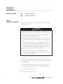
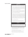
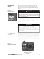
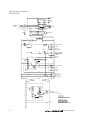
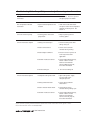
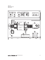
1
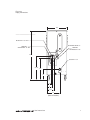
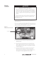
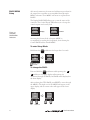
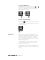
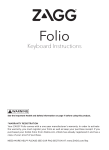
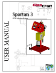
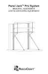
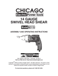
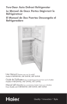
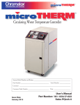
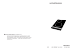
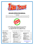
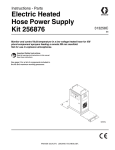
Circulating Oil Temperature Control System System Model Number and Rating_____________________________________________________ Part Number ________________________________________ Serial Number ________________ Customer ________________________________________________________________________ Customer Order Number__________________________ Date _ _____________________________ Issue Date July 2012 User’s Instruction Manual Part Number: 161-123417-025 PQ446-1 User Instructions User Instructions Table of Contents______________________________________________ SectionTopic Page 1 Getting Started..................................................................................................... 1 2 Installation............................................................................................................ 4 3 Temperature Control ......................................................................................... 10 4 Operation............................................................................................................ 15 5 Diagnostics.......................................................................................................... 18 6 Maintenance........................................................................................................ 20 7 Troubleshooting.................................................................................................. 26 8 Specifications....................................................................................................... 28 9 Index.................................................................................................................... 31 User Instructions i Illustrations____________________________________________________ FigureTopic Page 1.1 System Photo..........................................................................................................2 1.2 Control Panel.........................................................................................................3 2.1 Piping......................................................................................................................6 2.2 Piping Connections................................................................................................7 2.3 Power Connection Terminals.................................................................................8 2.4 Control Voltage Fuse..............................................................................................9 3.1 Control Panel Layout............................................................................................10 3.2 Controller Displays ...............................................................................................11 3.3 Controller PAGE/MENU Selections...................................................................12 5.1 Diagnostic Indicators............................................................................................18 5.2 Pump Reset Switch................................................................................................19 5.3 Over Temperature Controller Reset Switch..........................................................19 6.1 Electrical Schematic, Heat, Cool..........................................................................23 6.2 Electrical Schematic, Heat, Cool, SCR.................................................................24 8.1 Pump Capacity......................................................................................................28 8.2 Power and Capacity Information..........................................................................28 8.3 Replacement Parts Identification..........................................................................29 ii User Instructions Section 1 Getting Started________________________________________________ Section Contents Introduction System Photo Important Read and understand all instructions in this user’s manual and the enclosed 2104 temperature control instruction manual before attempting to install or operate system. Introduction Congratulations on purchasing the Chromalox microTHERM™ Oil Temperature Control System. This system has been thoroughly engineered, carefully built, and fully tested to assure years of service. The microTHERM™ Oil can be operated at a maximum temperature of 550°F. Oil temperature is maintained by a microprocessorbased temperature controller which applies heating and cooling as needed. Electrical and hydraulic components are located in distinctly separate areas in the system to better manage heat buildup and prevent component damage. It is designed to drastically reduce the chance of oil dripping inside the product and provide ease of service and maintenance. Standard casters make it easy to move the system from machine to machine. Power requirements for the system are 240 or 480 volts, 3 phase, 60 cycle, and 6 to 24 kW. See the system nameplate for the appropriate voltage and wattage ratings. Oil or other synthetic fluids or mineral based fluids may be used with this product. See section 4 number 1. The System Photo and Control Panel Illustrations, on the following pages identifies all key components. User Instructions 1 Figure 1.1 System Photo (Side View) Operating temperatures of 50° to 550°F for a wide variety of applications. Steel sheath Chromalox® heating elements. 3.2 sq. ft. heat exchanger (cooling) Integral with heating chamber. 3hp Centrifugal Pump. Cabinet design allows access to all components. Compact, rugged cabinet fits into tight spaces. Rolling casters allow easy transfer between locations. System Photo (Rear View) ASME safety relief valve opens if water pressure exceeds 125 psi, ensuring safe operation. Oil Outlet Cooling Water Inlet Cooling Water Outlet Integral solenoid valve for precise temperature control on cooling. Oil Inlet 2 User Instructions Figure 1.2 Control Panel CMXO Series Temperature Control System Pump START/STOP Pushbuttons Manual Cooling Switch User Instructions Status and Diagnostic Indicators Chromalox 2104 Temperature and Process Controller 3 Section 2 Installation____________________________________________________ Section Contents Before Hydraulic Installation Hydraulic Installation Electrical Installation Before proceeding with the installation please take note of the following information: WARNING Hazard of Explosion, Fire and Scalding Burns 1. The cooling water feed line must not have any obstructions which could cause buildup in pressure. 2. When installing system, allow sufficient room to remove the heater element and other serviceable items when necessary. 3. To avoid excessive pressures, do not connect any valves or obstructions which could prevent free discharge from relief valve in a safe manner. Vent outlet of pressure relief valve to a drain where steam or scalding water will not cause personal injury. Do not allow drain to freeze or corrode shut. 4. Use only on concrete floor or other nonflamable surface. Use in an open area with at least 1 foot clearance from walls and combustible materials. 1. This product is designed to roll over smooth flat floors. Do not roll over uneven floors and on ramps. Do not move while hot or containing fluid. 2. Reduced diameter fittings may be used down to 1” if they do not reduce flow rate and increase pressure drop significantly. 3. Use softened water for cooling. 4. Use and maintain oil filters. 4 User Instructions Hydraulic Installation WARNING Hazard of Explosion, Fire and Scalding Burns 1. Connect the 1/2” NPT port identified as “COOLING OUTLET” to an open or plant drain that contains no valves or obstructions that could impede discharge. Review the condition of potential hot water or steam going down a plant drain. Verify that local codes and materials are acceptable for this service. 2. This system is for use only with liquid phase heat transfer fluids suitable for a max bulk temperature of 550°F at atmospheric pressure. Use with any other fluids could result in death, personal injury, fire or damage to the equipment. 3. Do not place valves in vent line or allow vent line to become even partially clogged. Vent line on the expansion tank must be piped to a safe area and/or catch drum. Provisions must be taken to allow constant slope on vent to allow draining and to prevent liquids from collecting in the vent pipe. Vent should be periodically checked to verify it is free and clear of all obstructions. Vent piping should be no smaller than connection on the system. Do not place valves in vent line as system must remain vented at all times. 4. Do not overfill expansion tank. 5. Do not allow heat transfer oil to saturate insulation. Failure to comply could result in personal injury or property damage. Important Read and understand all instructions in this manual and other manuals shipped with the system prior to installation. All work specified within this instruction sheet should be performed by qualified personnel as required (electrician, plumber or mechanic). 1. System should be mounted on a solid level foundation. Where required, containment area should be provided in case of fluid loss. The system should be installed at the same level or higher than the process to be heated. 2. Before installing, check that all mounting bolts on equipment are tight. These sometimes loosen in shipment. 3. Piping to and from the process should match the piping on the system. If extremely long runs of pipe are to be used, one 6 User Instructions 5 Hydraulic Installation (continued) size larger than the system connections can be used to minimize pressure drop. Piping should be arranged to be self-supporting and not supported by the heat transfer system. On long runs, isolation from thermal expansion should also be provided. If the above are not taken into consideration, unnecessary stress will be put on the pump and/or piping. 4. Thread sealant and/or gaskets used on process piping should be rated for temperatures and heat transfer fluid to be used. Check with manufacturer for compatibility. 5. The piping of the entire system should be arranged to minimize pockets where air may be trapped. Manual bleed valves must be provided at any location where air may be trapped. 6. Connect the cooling water supply (30 psi to 80 psi) to the unit’s 1/2” NPT “WATER SUPPLY/COOLING INLET” port with suitable pipe or hose. Figure 2.1 Piping VENT SAFETY RELIEF VALVE TO SAFE AREA 6 User Instructions Figure 2.2 Piping Connections 18.6 ___________________ OIL/OUTLET 1-1/2" NPT HEATER DRAIN 1/2" COOLING WATER/INLET 1/2" NPT COOLING WATER/OUTLET 1/2" 45.1 OIL/INLET 1-1/2" 22-3/8 20 10 3-3/4 5 6-1/4 12 (Back of Product) User Instructions 7 Electrical Installation WARNING Hazard of ELECTRIC SHOCK 1. Disconnect all power before installing or servicing the heat transfer system. This system must be installed by a qualified person in accordance with National Electric Code, NFPA 70. Failure to comply can result in personal injury or equipment damage. 2. The heat transfer system must be effectively grounded to the grounding means provided in control box in accordance with National Electric Code. Fusing or other over-current protection must be supplied to the system by the user. The unit is completely wired when shipped. The only wiring necessary is to the blue colored terminals L1, L2, L3, and the green-andyellow colored ground. To make these connections: Figure 2.3 Power Connection Terminals L1, L2, L3 1. Loosen the screw on the front electrical enclosure door to unlock the latch. 8 2. Open the front electrical enclosure door. Using 90°C wire sized per National and local codes, run each leg of the three phase supply power and ground to the appropriate terminals as shown in Figure 2.3. 3. A separate fused disconnect is required. Locate this fused disconnect near the equipment. Codes may require the location of disconnect in sight of operation standing next to the equipment. Consult applicable codes for details. User Instructions 4. With power off, check the wiring connections by tugging on the lines. Tighten all terminals in the control area. These can loosen due to vibration in shipping. Pump Rotation Check 5. Close the front electrical enclosure door. Pull the top cover off of the heat transfer system and locate the pump motor. 6. Press the START and STOP buttons in quick succession. Watch the rotation on the pump motor to insure it matches the label. 7. If rotation is incorrect, disconnect power to the system and swap any two of the supply lines. Repeat rotation check. WARNING ELECTRIC SHOCK HAZARD Close the front electrical enclosure door and retighten the locking screw. This must be done to limit access to high voltage components. Failure to comply result in personal injury or equipment damage. Control Voltage Fusing Figure 2.4 contains a 120V fuse for the control circuitry. This fuse protects the control transformer and circuitry. 1. Should the fuse blow, an indicator will light on the terminal block. 2. Disconnect power from the system. 3. Determine the cause of the blown fuse. 4. Replace with an equivalent fuse. 5. Reconnect power. Figure 2.4 Control Voltage Fuse User Instructions 9 Section 3 Temperature Control Operations_______________________________ Control Panel Temperature Controller Operation Figure 3.1 Control Panel Layout Outlet Pressure “To Process” Inlet Pressure “From Process” CMXO Series Temperature Control System START/STOP Pushbuttons Status and Diagnostic Indicators Temperature Controller Press START to start the pump. System shuts down if any red diagnostic indicator is illuminated. Top Display reads current system outlet temperature. Pump Overload: • Pump has drawn too much current. Bottom Display reads setpoint temperature. Indicator will illuminate while pump is running. Press STOP to stop the pump. Over Temperature: • System temperature has exceeded 600°F. Pump Running Heating Cooling 10 Manual Cooling: • If manual cooling is on, heaters shut off and water cooling is on. Normally this is off and the temperature controller determines when to heat or cool. Press ▲ to increase setpoint temperature. Press ▼ to decrease setpoint temperature. OUT 1 • Heat is being applied. OUT 2 • Cooling is being applied. AUX • Indicates system is in Standby. User Instructions Temperature Controller Operation The Chromalox® 2104 1/4 DIN temperature controller is a highperformance, single-loop controller. The 2104 controller has two control outputs for heating and cooling that can be configured separately and provide flexible temperature control. A dual digital display of current process temperature and setpoint temperature make the system easy to understand and operate. The 2104 controller has extended capabilities and functions for more technically advanced applications. To learn more about how these controller capabilities may be used, consult the enclosed 2104 Controller Technical Manual, part number, 0037-75276. Figure 3.2 Controller Displays OUT 1 • Indicates Heat ON OUT 2 • Indicates Cool ON • • System Outlet Temperature Display Alphanumeric Menu Display in Setup Mode LEDs indicate °F or °C selected for Process Temperature LED indicates the controller is in Standby mode Setpoint Temperature Display User Instructions 11 PAGE/MENU Setup All control parameters, selections and calibration procedures for the temperature controller are accomplished through simple MENU selections. These MENU selections are organized into PAGES. The Display PAGE (DISP) allows you to view the status of the controller. The Control Page (CTRL) allows you to change the control setpoint and security lock. DISP Figure 3.3 Controller PAGE/MENU Selections PAGE CTRL PAGE Display RESET AUX Control RESET AUX Accessing the Security Lock or Setpoint MENU is accomplished by entering the Setup Mode, then selecting the Control PAGE and the desired MENU. To enter Setup Mode: Hold down the 250 250 RESET RESET pushbutton LOCH ➪ AUX 123 AUX RESET Hold for at least 3 seconds. for longer than 3 seconds. Setup Mode entered. To change the PAGE: Press and hold the RESET pushbutton while pressing the ▲ or ▼ pushbutton. the upper display will increment (or decrement) through the PAGEs, and PAGE will be displayed in the lower display. After reaching the CTRL PAGE, press RESET to move through the MENUs. The alpha cue for the MENU will appear on the upper display, and the current value will appear in the lower display. SP 250 RESET Hold 12 AUX ➪ CTRL PAGE RESET AUX Press ▲ or ▼ User Instructions To change a MENU value: After the MENU is selected and displayed, use the ▲and ▼ pushbuttons to change the value. For large adjustments (for example, 100 to 200), hold the pushbutton pressed and the display will change more quickly. SP 100 RESET SP ➪ AUX 200 RESET AUX To return to Operating Mode: Press and hold RESET for more than 3 seconds. The controller will automatically return to operating mode after 10 minutes of no pushbutton activity. STBY 101 RESET AUX Hold for at least 3 seconds. Security Code Every parameter or selection in the 2104 controller’s setup PAGEs has an identifying MENU. The MENUs are accessible only if the correct Security Code is entered. This allows you to set the Security level that is appropriate for your operating environment, prohibiting unauthorized access to or accidential changing of control parameters. The microTHERM™ system is factory preset to security code 123. To adjust any of the controller’s setup parameters, the security code must be set to 458. The Security Code is entered on the Control PAGE CTRL, at the MENU LOCH. This code determines which MENUs may be adjusted. User Instructions 13 To access and enter the Security Code: 1. Press and hold RESET for more than 3 seconds to enter Setup Mode. Security Lock is the first menu that will appear (LOCH). 2. To change the Security Code, press ▲ or ▼ until the correct security code is displayed (458 to change controller setup). LOCH 123 RESET AUX 3. Reference the factory preset MENU settings (Figure 8.2, page 35), when replacing the controller or if the settings have been changed. CTRL PAGE RESET AUX Control Page Menu Description LOCH Security Lock SP Setpoint 14 Available Settings 0 to 9999 Instrument sensor span Factory Settings 123 32°F Security A B User Instructions Section 4 Operation______________________________________________________ CAUTION Damage to the pump and/or heater may occur if the system is operated without fluid. Fill system prior to starting. Operate in 105°F or less surrounding temperature. Note: Read and understand instructions on the temperature control before operating the system. 1. Check to ensure the fluid is the same as or compatible with the fluid with which the system was factory pretested. (Mobiltherm 603) Important For disposal see fluid manufacturer’s recommendations. 2. The system is filled with heat transfer fluid directly from the 55 gallon drum by simply connecting a hose from the expansion tank (located on the top of the system) to the drum. Fill expansion tank until sight glass indicates it is approximately 1/3 full. 3. The overheat temperature control is located inside the control panel. Setpoint should be adjusted 50°F higher than the indicating temperature control. WARNING: Never exceed a setting of 600°F on the overtemperature control. 4. Close control box door and turn circuit breaker on. Start pump — do not be alarmed if the pump is noisy during the initial start-up operation, this is due to air in the system. 5. Bleed out all air by opening bleeder valves in the customer’s piping. The pump should become quiet. CAUTION: During the initial start-up operation, the liquid level in the expansion tank must be checked continually. This level should not exceed the three-quarter mark on the glass nor drop below the one-quarter mark. Note: If abnormal fluid expansion is detected, this is probably due to a pocket of air or steam still present in the system. Check all bleed valves. If problem continues, de-energize pump and check bleed valves. 6. Set indicating or controlling thermostat at 220°F, which will energize the heater. The heater is interlocked with the pump motor starter so that, in the event of motor failure, the heating elements will shut off automatically. User Instructions 15 7. Run the system until 220°F is reached. Periodically open the bleed valves in the customer’s piping to remove air from the system. At 220°F any moisture that has been trapped in the system will flash into steam as it goes through the heater and can be bled out through the bleed valves. 8. Excessive moisture and air in the system will cause the heat transfer liquid to back up into the expansion tank, thus evacuating the piping or process. If this happens, shut the system down, bleed off the steam and air allowing the liquid to return. If problem persists, drain the system and recharge with new moisture-free heat transfer liquid. 9. After the system is completely free of air pockets and moisture, set control thermostat at the desired temperature. Never set temperature control above 550°F. 10. For detailed operation and tuning procedure on the temperature control, consult instruction manual on the temperature control. Note: Consult Service Manual PQ410 for additional aid to help start-up and to service Chromalox Heat Transfer Systems. WARNING BURN Hazard Operating systems at temperatures above 140°F will create surface temperatures on pipes that can cause burns. Precautions should be taken to prevent operator contact with hot pipes. Also, bleed valves should be locked down to prevent release of hot fluid. ☛ Note: This is a PID type controller and cycling of the heat and cool can be expected below and above setpoint. 11. For system shutdown, lower the setpoint to 90°F or lower (see Section 3). Allow the system to cool to this temperature. 12. Press STOP to de-energize the pump and disable the system. 13. Disconnect power to the unit. WARNING ELECTRIC SHOCK AND BURN HAZARD Do not leave system unattended in a HOT electrical condition. Do not leave system unattended while HOT. 16 User Instructions Manual Cooling If manual cooling is on, heaters will be off and water cooling will be on. Normally, manual cooling is off and the temperature controller determines when to heat or cool. Manual cooling is optional. To use manual cooling: 1. Turn manual cooling on and observe temperature. 2. Optional. If at a safe temperature, you may stop the pump until you are ready to run again. Important, even if the pump is off, cooling water will run to the heater as long as manual cooling is on and there is electricity to the product. 3. When ready, turn pump on and turn manual cooling off. The temperature controller will heat or cool to the desired temperature. Important, even if electricity is turned off to the product, when electricity is turned on, the temperature controller will go back to the previous temperature before manual cooling. If this is not desired, it is best to use the temperature controller instead of manual cooling. User Instructions 17 Section 5 Diagnostics____________________________________________________ Section Contents Pump Overload Over Temperature Etire CMXO Series Figure 5.1 Temperature Control System Diagnostic Indicators Diagnostic Functions 18 All red light diagnostic functions will shut down the system and require the operator to remedy the problem before it can be restarted. User Instructions Pump Overload Indicator The Pump Overload Indicator will illuminate when the pump draws too much current. Low line voltage, single phase power input, and a seized pump motor are all possible causes for pump overload. Figure 5.2 Pump Reset Switch WARNING ELECTRIC SHOCK HAZARD If the Pump Overload Indicator is illuminated, disconnect all power and piping to the system. Failure to do so could result in personal injury or equipment damage. Pump Reset Switch After the system power is disconnected, solve the electrical current problem. To put the pump back on-line, open the front electrical enclosure and press the pump reset switch. See Figure 5.2. WARNING ELECTRIC SHOCK HAZARD Close the front electrical enclosure door and retighten the locking screw. This must be done to limit access to high voltage components. Failure to comply could result in personal injury or equipment damage. Over Temperature Controller If the system temperature exceeds 600°F (315°C), the Over Temperature Indicator will illuminate. When the system temperature drops below 550°F, press reset on the over temperature controller inside the panel. Close door and retighten the screw. The controller will not reset until the temperature is below 600°F. Or remove electricity to the product and the over temperature controller will reset after temperature is below 600°F. Figure 5.3 Over Temperature Controller Reset Switch LIMIT-10100 Limit Control R Over Temperature Controller Reset Switch User Instructions 19 Section 6 Maintenance_________________________________________________ Section Contents Take Out Of Service Heater Removal/Replacement Pump Removal/Replacement WARNING ELECTRIC SHOCK AND BURN HAZARD Disconnect all power before servicing or performing maintenance to the system. Do not attempt to service system while it is operating or while hot. Failure to comply can result in: a. Electric shock. b.Burns from hot heating elements, piping, and hot oil or water. c. Injury from operating or rotating pump and motor. Maintenance is to be performed by qualified personnel only. Thoroughly read and understand these instructions. Consult the factory if you have any questions. Take Out Of Service To take the unit out of service, the following steps must be done in sequence: 1. Set the temperature controller setpoint to 90°F or lower. Allow to cool. 2. Turn off power to the unit. The controller will turn off. 3. Turn off the water supply to the unit. 4. Disconnect electrical supply to the unit. 5. Drain the system. 6. If it is exposed to freezing temperatures while out of service, remove water by blowing air through cooling pipe. You will need to open the cooling valve by turning on manual cooling or removing it. 20 User Instructions Heater Removal/Replacement WARNING ELECTRIC SHOCK HAZARD Disconnect all power to system before servicing. Failure to comply can result in personal injury or equipment damage. BURN HAZARD Never service system while hot. Allow system to cool to room temperature before servicing. 1.Check that power is disconnected from the system and remove wiring to heater. 2. Disconnect thermocouple from control cabinet. 3. Drain heater and pump. 4. Remove bolts on heater and undo fittings on pipe. Remove heater through the front door. 5. Install new heater and retighten all bolts and fittings. 6. Put all sheet metal back in place and retighten screws. 7. Refill system and follow operation procedure in Section 4. LEAKS 1. Leaks should be minimized. 2. CAUTION: Hazard of Fire. Some heat transfer fluids are flammable and if allowed to leak on hot pipes or in fibrous thermal insulation, a fire hazard can be created. 3. Disassemble, clean and reseal the connections using high temperature sealant. (Do not use TFE or other tape.) Sealants are to be rated for temperatures and fluids used in the system. WARNING ELECTRIC SHOCK HAZARD Close the front electrical enclosure door and retighten the locking screw. This must be done to limit access to high voltage components. Failure to comply could result in personal injury or equipment damage. User Instructions 21 Pump Removal/Replacement WARNING ELECTRIC SHOCK HAZARD Disconnect all power to system before servicing. Failure to comply can result in personal injury or equipment damage. BURN HAZARD Never service system while hot. Allow system to cool to room temperature before servicing. 1. If pump requires service, drain system and remove top and side panels. 2. Pump/motor can be removed from the system as an assembly for service. 3. Disconnect piping at unions on inlet and outlet piping leading to the pump. 4. Remove four bolts which hold the pump/motor base to the base of the system. 5. After verifying power is disconnected remove conduit and wiring from the motor. 6. Lift out pump/motor assembly. 7. Service pump per pump manufacturers instructions. 8. If replacing the pump, be sure to remove piping from old pump casing before discarding. Clean thread on pipe and thread into new pump casing using high temperature oil resistant thread sealant. DO NOT USE TFE OR OTHER TAPE SEALANTS. 9. Install new pump in system reconnect piping. 10. Reconnect wiring and check rotation as indicated in “INSTALLATION” section. WARNING ELECTRIC SHOCK HAZARD Close the front electrical enclosure door and retighten the locking screw. This must be done to limit access to high voltage components. Failure to comply could result in personal injury or equipment damage. 22 User Instructions Figure 6.1 Electrical Schematic, Heat, Cool DISCONNECT SWITCH 2GND HEATER 1M OL L1 GND 1T1 1T2 1T3 2T1 L2 2T2 L3 2T3 MOTOR PUMP MOTOR 1GND REFER TO TRANSFORMER LABEL FOR VOLTAGE WIRING 1 DI-1 B3 B1 5 2 3 STOP R4 START OL R5 95 2PB-1 1M-1 1PB-1 4 13 5 R6 1M MOTOR CONTACTOR A1 A2 SNUBBER A 1M-2 R7 96 14 MANUAL COOLING OFF ON ( ) R9 (X0) 1C 1SS-1 S 6 7 W2 90VA X2 1F 1 53 R8 54 ITC 8 OUT1 10 11 SEE LINE 10 24 11 12 1 16 13 T/C - - T/C + + A 1TE TYPE "J" T/C N 177 R11 1 12 OL-1 98 INDICATOR 'HEATING' SNUBBER OFF ON ( ) R11 (0X) 1SS-2 S 15 16 HEATER CONTACTOR W2 2104 14 INDICATOR 'PUMP RUNNING' SNUBBER G 9 OUT2 R12 97 17 OFF ON 18 1SS-3 ( ) R13 (0X) A INDICATOR 'COOLING' R INDICATOR 'PUMP OVERLOAD' A INDICATOR 'MANUAL COOLING' COOLING SOLENOID CONTINUED BELOW B3 W2 19 OTC 20 21 22 2TE TYPE "J" T/C + - T/C+ 6 T/C7 PWR 3ÿ POWER L1 L2 L3 L1 L2 L3 PWR CUSTOMER 1C 23 8 25 9 26 RESET 24 L1 1 L2 2 NC 3 4 C 5 B3 R R10 INDICATOR 'OVER TEMPERATURE' 10 SEE LINE 11 4-12KW @ 208V 4-18KW @ 240V 4-24KW @ 480V LIMIT-10100 MOTOR WIRE: 12GA 125°C ° POWER WIRE: 10GA 250 C 27 28 M User Instructions ENCLOSURE FAN HEATER GND WIRE: 10 GA, 250°C 23 Figure 6.2 Electrical Schematic, Heat, Cool, SCR DISCONNECT SWITCH 2GND 4003 + SCR PWR CTL A1 A 1C L1 L2 L3 L1 CUSTOMER CONNECTIONS L2 3ÿ POWER L3 GND 1M OL L1 1GND GND G L1 1 L2 3 L3 5 + A A1 - - A A2 SEE ITC LINE 9 T1 2 HEATER 4 T3 6 2T1 L2 2T2 L3 2T3 MOTOR PUMP MOTOR L1 L2 1 DI-1 B3 5 B1 1F 1 2 START 3 CPT X1 90VA X2 13 5 95 96 R6 MOTOR CONTACTOR 1M A2 A1 SNUBBER 14 A MANUAL COOLING ON R8 ( ) R9 (X0) 6 7 W2 OL R5 2PB-1 1M-1 4 REFER TO TRANSFORMER LABEL FOR VOLTAGE WIRING 1M-2 R7 SEE LINE 22 6 54 53 1SS-1 1C 8 ITC + - 12 13 + 8 9 L 1 16 177 G 18 14 A OUT1 1TE TYPE "J" T/C + 100 + A1 A - ZONE D-3 A22 A C 11 NO 12 B3 ((0X)) R10 COOLING SOLENOID 1SS-2 SS R10 SNUBBER 2104 15 A INDICATOR 'COOLING' R INDICATOR 'PUMP OVERLOAD' INDICATOR 'MANUAL CO0LING' W2 16 OL-1 17 INDICATOR 'HEATING' B3 PWR 11 HEATER CONTACTOR SNUBBER 9 10 INDICATOR 'PUMP RUNNING' 98 R11 97 ( ) R12 (0X) 18 1SS-3 A CONTINUED BELOW B3 W2 19 21 2TE TYPE "J" T/C 22 + - T/C+ 6 T/C7 23 8 25 9 RESET 24 PWR OTC 20 L1 1 2 3 NO 4 C 5 R13 R7 R INDICATOR 'OVER TEMPERATURE' 6 SEE LINE 7 4-12KW @ 208V 4-18KW @ 240V 4-24KW @ 480V 26 MOTOR WIRE: 12GA 250°C HEATER WIRE: 8GA 250°C 27 28 M ENCLOSURE FAN ° HEATER GROUND WIRE: 10GA 250°C 29 30 24 User Instructions Maintenance Record Date Maintenance Record User Instructions 25 Section 7 Troubleshooting_______________________________________________ Troubleshooting Guide—For qualified personnel only. See warnings in earlier sections. Symptom Unit will not start, control display does not light. Probable Cause Correction 2.Disconnect switch OFF. 2.Turn disconnect ON. 1.Unit not wired correctly. 1.Check wiring. 3.Blown fuse. 3.Check customer disconnect fuses and 120V fuse on terminal block (blown fuse indicator will light if fuse is blown). 4.Wrong voltage. 4.Check supply voltage and unit’s rated voltage. Control display lights, unit will not start. 1.Pump motor overload. 1.See Section 5. Determine problem and press pump reset. 2.System above temperature 2.Allow unit to cool below 550°F temperature controller inside the panel. See Section 5. limit of 600°F. and press reset on over Unit stops while running. 1.Pump motor overload. 1.Determine problem, press pump reset, and restart. 2.System exceeds temperature 2.Allow unit to cool below 550°F, press reset on over temperature controller inside the panel, and restart. See Section 5. limit of 600°F. continued 26 ➔ User Instructions Troubleshooting Guide—For qualified personnel only. See warnings in earlier sections. Symptom Probable Cause Correction Pump Overload Indicator 1.Pump motor overload. 1.See Section 5. Determine problem illuminated. and press pump reset button. Over Temperature Indicator 1.System above temperature limit 1.Allow unit to cool below 550°F illuminated of 600°F. and press reset on over temperature controller inside the panel. See Section 5. Unit runs but fails to pump. 1.Incoming phase reversed on 1.Swap any two legs on the pump motor. incoming power. Unit will not heat to setpoint. 1.Cooling valve stuck open. 1.Check for cooling water flow during heat cycle. 2.Heater element failure. 2.Check current at heater contactor during heating. 3.Heater output insufficient. 3.Excessive losses in process or incorrectly sized unit for application. 4.Controller needs to be tuned. 4.Check factory MENU settings, Section 3 of this manual. Refer to 2104 Controller Technical Manual, page 35, for further information. 5. Manual cooling on. 5. Turn manual cooling off. Unit will not cool to setpoint. 1.Inadequate cooling water flow. 1.Open cooling water supply line more and assure adequate pressure. 2.Cooling outlet obstructed. 2.Check cooling outlet for obstructions. 3.Heater contactor fused closed. 3.Check voltage across contactor during cooling cycle. 4.Controller needs to be tuned. 4.Check factory MENU settings, Section 3 of this manual. Refer to 2104 Controller Technical manual, page 35, for further information. If you continue to have problems with the system after review of the above issues, please contact Chromalox Product Service at 800-443-2640. User Instructions 27 Section 8 Specifications________________________________________________ Pump Size (HP) Nominal Oil Water Flow Connections (gpm) (inches dia.) (inches dia.) Approximate Dimensions (inches) 45 height 3 30 1 1/2 NPT 1/2 NPT 38 depth 19 width Figure 8.1 Pump Capacity Ft. 0 (As reported by 140 pump manufacturer on Model HTO-80; 120 Size 1.5 x 1.25; Speed 3450 RPM; 100 S.G. (.85)). 80 60 40 20 0 Figure 8.2 Power & Capacity Information 10 20 30 40 60 70 50 U.S. Gallons Per Minute BTU’s Nominal Amps* Volume kW Per Hour 240V 480V (Gal.) 80 90 Heat Exchanger Surface Area (Ft.) 4 6 15,354 21.4 10.7 6.1 3.2 20,472 26.2 13.1 6.1 3.2 9 30,708 33.4 16.7 6.1 3.2 12 40,944 40.7 20.3 6.1 3.2 18 61,416 54.7 27.5 6.1 3.2 24 81,888 34.6 6.1 3.2 *Total per leg based on 3 phase, 60 cycle power with heater at rated voltage, motor at rated output, and control transformer at full load. Measured value may vary depending on conditions. 28 User Instructions Figure 8.3 Replacement Parts Identification 9 25 8 11 11 12 10 10 12 2104 TT100 7 or 22 CAUTION-DO NOT SET TEMPERATURE ABOVE 600 DEGREES F 20 13 24 19 21 SCR PWR CONTROLLER OPTIONAL 14 CONNECT ____VOLT SUPPLY HERE 23 16 15 FAN User Instructions 29 Replacement Heaters kW Replacement Parts Voltage Heater 6 240 480 052-305096-001 052-305096-002 9 240 480 052-305096-007 052-305096-008 12 240 480 052-305096-005 052-305096-006 18 240 480 052-305096-003 052-305096-004 24 480 052-305096-001 Replacement Parts Common to All Models Identification # Part Name Part # 1 ............................. 3 HP Pump & Motor 230V/460V..............................................226-304843-002 Pump Rebuild Kit (Seal, Gasket, etc.)...............................251-121946-032 2 ............................. Solenoid Valve................................................................................344-072237-021 3 ............................. Safety Relief Valve.........................................................................344-300032-103 4 ............................. Pressure Gauge 0-100psig........................................................130-118661-037 5 ............................. Pressure Gauge 30” Vac - 30 psig..........................................130-118661-038 6 ............................. Thermocouple Process T/C................................................................................309-304460-036 Overtemp T/C............................................................................300-304460-012 7 ............................. Temperature Controller...............................................................309-123617-101 8 ............................. Push Button, Start.........................................................................292-304687-003 9 ............................. Push Button, Stop..........................................................................292-304687-004 10 ............................. Light, Red.........................................................................................213-122066-041 11 ............................. Light, Amber....................................................................................213-122066-042 12 ............................. Light, Green.....................................................................................213-122066-043 13 ............................. Motor Contactor 240/480V........................................................072-123534-065 14 ............................. Auxillary Motor Contact Block.................................................071-122886-055 15 ............................. Motor Thermal Overload 240V.................................................359-122078-097 15 ............................. Motor Thermal Overload 480V.................................................359-122078-096 16 ............................. Transformer 240/480V.................................................................315-303786-001 17 ............................. Caster, Swival..................................................................................375-123425-006 18 ............................. Caster, Rigid....................................................................................375-123425-007 19 ............................. Control Voltage Fuse....................................................................303-123432-024 20 ............................. Heater Contactor...........................................................................072-304551-008 21 ............................. Over Temperature Controller.....................................................381-700400-297 22 ............................. Temperature Controller with digital communications - Call 1-888-996-9258 23 ............................. Fan......................................................................................................112-121869-005 24 ............................. SCR.....................................................................................................300-400360-610 25 ............................. On/Off Cooling Switch.................................................................292-304687-002 30 User Instructions Section 9 Index_________________________________________________________ Alarm •Latching 14 •Overtemperature 11, 14, 27 •Relay Action 14 Cabinet 2 Contactor 23, 30 Control Output #1 (Heat) 10, 11 Control Output #2 (Cool) 10, 11 Control Setpoint 10, 11, 14, 15, 16, 26, 30 Control Voltage Fusing 9, 30 Controller •Temperature Controller 1-3, 10, 11, 12, 17, 19, 30 Cooling, Control 10, 11, 17 Cooling, Manual 17 Cooling Solenoid 23 See Valve, Cooling Cooling Water Valve 2, 26, 27 Diagnostic Functions 18 Diagnostic Indicators 3, 10, 18 •Over Temperature 10, 14, 18, 19, 23, 27 •Pump Overload 10, 18, 19, 27 Display, Control 11, 26 Motor 6, 9, 15, 19, 20, 22, 23, 26, 27, 30 Motor Contactor 23, 30 Motor Control 10, 19 Operating Mode 13 Operating Temperature 2 Output Relay #3 14 Output Relay #4 14 Overtemperature Indicator 10, 14, 18, 19, 23, 27 Power Requirements 1, 28 Pressure Gauges 30 Process Temperature 11, 14, 15, 16, 19 Pump 2, 3, 6, 9, 10, 15-22, 26, 27, 28, 30, 31 •Pump Indicator Light 19, 23 •Removal/Replacement 20, 21 •Rotation Check 9 Pump Capacity 28 Pump 9, 15, 19, 20, 22, 23, 26, 27 Pump Reset Switch 19, 26 Replacement Parts 29, 30 Schematic, Electrical 23, 24 Indicators •Cooling 10, 23 •Diagnostic 10, 18 •Heating 10, 23 •Overtemp 10, 14, 18, 19, 23, 27 •Pump Overload 10, 18, 19, 27 Safety Relief Valve 2, 4, 30 Security Code 13, 14 •Access 2, 9, 12, 13, 14, 19 •Change 2, 12, 13, 14, 28 Security Lock 12, 14 Service 20, 30 Setpoint 10, 11, 12, 14, 15, 16, 20, 27 •Change 10, 14, 27 •Control 10, 11, 14, 15, 16, 26, 30 •Temperature 1-3, 5, 6, 10-12, 14-22, 26, 27, 30 Setup Mode 11, 12 Shutdown 16 Solenoid Valve 2, 30 Specifications 28 Switch •Pump Reset 19 kW 28 Troubleshooting 26 Leaks 21 Valve •Cooling 1, 2, 4-6, 10, 11, 17, 20, 26, 27, 30 •Safety Relief 2, 4, 30 •Solenoid 2, 30 Vent 5 Electrical Installation 8 Fusing 8, 9 •Control Voltage 9, 30 Hazard 4, 5, 8, 9, 15, 16, 19, 20, 21, 22 Heater 4, 15, 16, 17, 20, 21, 27, 28, 30, 31 •Removal/Replacement 20, 21 Manual Cooling 10, 17 MENU Selections 12 •Control 12, 13, 14 •Display 11, 12 •Setup 12 MENU Value 13 Wiring Diagram •Heat, Cool 23 •Heat, Cool, SCR 24 User Instructions 31 32 User Instructions