1
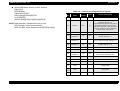
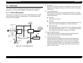
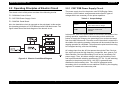
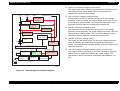
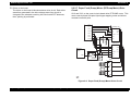
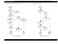
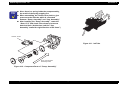
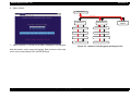
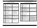
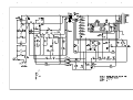
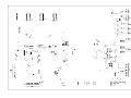
EPSON Stylus Photo 750
+42 VDC
Revision A
+5 VDC
† +42V Line Constant Voltage Control Circuit:
The output level of the +42V line is monitored by a detection circuit
consisting of seven Zener diodes.This circuit prevents from
dropping for constant output voltage.
PSC Signal
from Main board
ZD53
† +5V Line Over Voltage Protection Circuit:
This protection circuit is in the same line as +42V over voltage
protection circuit is located. The output voltage level of the +5V line
is monitored by a Zener diode. This circuit shuts down the circuit
operation forcefully when the voltage level exceeds +9V.
+5VDC Line
Over Voltage
Limitation
IC51
+5V Regulator
ZD52,87
+42VDC Line
Over Voltage
Limitation
ZD90
† +42VDC Line Drop Limitation Circuit:
This protection circuit is in the same line as +42V over voltage
protection circuit is located. The output voltage level of the +42V line
is monitored by a Zener diode. This circuit shuts down the circuit
operation forcefully when the voltage levels drops +36V.
+42VDC Lin Drop
Limitation Circuit
ZD81-86,ZD51
+42VDC Line
Constant Control
C84,Q84
Power Drop
Delay Circuit
C51
Smoothing
Circuit
† +42VDC Line Over Voltage Circuit:
This circuit is in the same line as +5V line over voltage protection
circuit is installed. The output level is monitored by two Zener
diodes. If the voltage level exceeds +48VDC, this circuit stops circuit
operation forcefully.
PC1
Photo
Coupler
D51
TRANS(T1)
C11
Smoothing
Circuit
Over Current
Protection
F1
Abnormal
Feed back circuit
Main Switching
Circuit
Filter Circiut
L1,R1-2
C1-C4
† +5V Line Constant Voltage/Constant Current Control Circuit:
The output current is monitored by a +5VDC generation switching
control IC(IC51), which also monitors the output voltage. This
information is input to the internal comparator and stabilizes +5V
line.
Q2,Q3,Q31
Q1
Full Wave
Rectifier circuit
DB1
AC Input
op03
Figure 2-3. Power Supply Circuit Block Diagram
Operating Principles
Operating Principles of Electric Circuit
31