1
Instruction Leaflet
IP258
November 2004
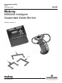
Mobrey
MSM400 Intelligent
Suspended Solids Monitor
Software Version 1.1
www.mobrey.com
Level
CONTENTS
Page
1.
PRODUCT INTRODUCTION
1.1
The MSM400 slurry monitoring system
1.2
Description
5
5
5
2.
SENSOR TYPES
2.1
Safety Precautions
2.2
Hazardous Area systems
2.3
Quick Start guide
7
7
8
3.
CONTROL UNITS
3.1
MSM400 Displays and Keypad
3.2
Specifications
9
9
10
4.
INSTALLATION
4.1
Preliminary Checks
4.2
Pipe Section Installation
4.3
Suspended Sensor Installation
4.4
Sensor Cabling
4.5
Control Unit
4.6
Electrical Connections
11
11
11
12
12
13
PROGRAMMING
5.1
Programme Structure
5.2
Navigation in the Menu System
5.3
Diagnostic Parameters
5.4
Ex-Factory System Features
16
19
18
18
CALIBRATION
6.1
Zero Setting
6.2
Re checking Zero
6.3
Auto cal zero setting procedures
6.4
Auto cal span setting procedure
6.5
Auto cal lab values
6.6
Maximum % solids
6.7
Calibration - Alternative method
6.8
Zero setting procedure
6.9
Span Calibration Methods
6.10 Method 1-Slurry Type
6.11 Method 2-Sample Calibration
6.12 Method 3-Attenuation Value
18
19
19
20
21
22
22
22
22
22
22
23
7.0
PROGRAMMING THE MSM400 FUNCTIONS
7.1
Outputs
7.2
Current output
7,3
Relay Operation
7.4
Alarm
7.5
Display
7.6
Back Light
7.7
Engineering
7.8
System
24
27
27
27
28
28
29
29
29
8.
HART SMART COMMUNICATIONS
30
9.
MAINTENANCE / INSPECTION
30
5.
6.
APPENDICES
A1.
Full Listing of Menu Structure
A2.
Full List of Programme Parameter Functions
A3.
HART and PSION Operating Instructions
D
Handheld Communicator - Assembly Instructions
31-32
33-37
38-40
41-59
Footnote :In this manual the following terms are used which refer to trademarks from other manufacturers:
HART: is the protocol adopted for the MSM400 SMART Communications.
HART is a registered trademark of the HART Communications Foundation and is a mnemonic For
Highway Addressable Remote Transducer.
PSION: is the trade mark of PSION plc who manufacture the PSION ORGANISER Hand held computer.
The MOBREY SMART program is stored in a DATAPAK which is also a trademark of PSION plc, and is an accessory
for the Model LZ Organiser
IP258
2
Safety Precautions
The following safety precautions should be observed before using this product or working on the attached cables.
This MSM400 product is intended for use by qualified personnel who recognize shock hazards and are familiar with
the safety precautions required to avoid possible injury. Read the operating information carefully before using the
product.
The types of product users are:
Responsible body: This is the individual or group responsible for the use and maintenance of equipment, and for
ensuring that operators are adequately trained.
Operators use the product for its intended function. They do not require access to the electrical connections within
the control box, and would normally only operate the external keypad and monitor the display.
Maintenance personnel perform routine procedures on the product to keep it operating, for example, checking the
line voltage or checking electrical connections, replacing mains fuses etc.
Service personnel are trained to work on live circuits, and perform safe installations and repairs of products. Only
properly trained service personnel may perform installation and service procedures. However, the only serviceable part
in MSM400 is the mains cartridge fuse.
Users of this product must be protected from electric shock at all times. Product users must be trained to protect
themselves from the risk of electric shock.
Before operating the instrument, make sure the mains supply is connected to a properly grounded power supply.
Periodically inspect the connecting cables for possible wear, cracks, or breaks. Check lid and glands are tight, also
check unit for damage and if damaged do not use.
The fuse may only be replaced with same type and rating for continued protection against fire hazard.
To clean the instrument, use a damp cloth or mild, water based cleaner. Clean the exterior of the instrument only. Do
not allow liquids to enter or spill on the instrument.
WARNING - If this equipment is used in a manner not specified by Mobrey Measurement, the protection provided
may be impaired. The MSM400 is regarded as permanently installed equipment and as such a double pole supply
isolating switch or circuit breaker must be included in the installation. This should be in close proximity to and not
be obstructed by the equipment. It should be marked as its disconnecting device.
A protective earth must be used for all applications.
The installation of the MSM400 and its associated power cables must be such that tank overflow, local flooding or
pump failure do not cause these to be submerged or subject to flows of water. Sensors and sensor cabling can be
submerged without hazard to equipment operators when correctly connected as described in this manual.
CHECK THAT THE POWER SUPPLY IS SUITABLE BEFORE SWITCHING POWER ON.
Internal adjustments can select mains 115 Volts AC power, which makes the equipment unsuitable for 230V AC
supplies. Check this Voltage selection switch compared to the available power supply.
Explanation of symbols:
The Protective earth terminal must be connected to an external Protective earthing system.
!
Refer to manual.
Hazardous area systems :Where the MSM400 is connected to sensors located in an explosive atmosphere additional instructions apply.
Refer to Safety Instructions IP258/SI
IP258
3
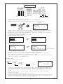
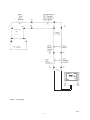
QUICK START
Green
Black
White
Black
White
Green
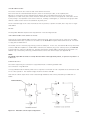
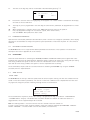
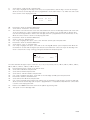
Terminal connections
SENSOR CONNECTION
1)
2)
3)
L IVE NEUTRAL EARTH
MAINS IN
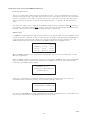
Connect the mains supply to the terminal connections L, N and E as shown above.
Connect the sensor to the terminals as shown above.
With power on, press a button on the key pad as shown below. This will access the main menu.
DISPLAY
MAIN MENU
TOGGLE RUN
CALIBRATION
SETUP
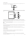
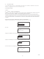
4)
5)
6)
11)
AUTOCAL
0
SETZERO
MAX % 0
SETSPAN
LAB VALUES
0
0
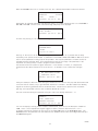
Highlight SETZERO and press ENT
SET ZERO
In clear liquor
Press
8)
9)
10)
0
Navigation around the menu system is achieved by using the up and down arrow keys to highlight an option and
the ENT key to accesss the various levels. Pressing ESC returns the user to the previous level.
Highlight toggle run and press ENT. PRESS ENT AGAIN to open the toggle run padlock. Press ESC to return to
main menu. Parameters may now be altered.
To calibrate the unit, highlight CALIBRATION and press ENT.
Now highlight AUTOCAL and press ENT.
CALIBRATION
AUTOCAL
MANUAL ENTRY
MAX %
7)
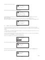
0
0
SET ZERO
In clear liquor
press ENT to set
16.2 dB
25.3 dB
0
0
0
-------------Signals from sensor
Follow the instruction then wait a few seconds.
When ENT is pressed the zero is set. Press ESC four times to return to normal display.
Follow the same procedure to set the span. i.e. Highlight SETSPAN in the AUTOCAL menu and press ENT.
Up to 3 SPAN values can be taken. Press down arrow to access next span.
When setting span, sludge samples should be taken for analysis. The results of the samples are the input to the
control unit for reference in THE LABVALUES menu.
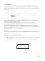
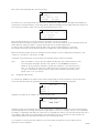
INPUTTING A VALUE
1)
Access the parameter as shown below :
CALIBRATION -
Manual/Entry
AUTOCAL -
ENT
0
SETZERO
SETSPAN
LAB VALUES
LabVal 1
-
ENT
------------------
0.00
%
P150
0
LabVal 1
LabVal 2
LabVal 3
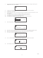
To input a value press the right arrow to highlight the correct digit to be altered. The value of the digit is then
incremented or decremented by using the up or down arrows. To save a value press ENT. 'ESC to return to menu'
Now input your expected max % solids required. Located in - Calibration - AUTOCAL - Max %. (See section 6 for
details)
All other parameters are setup in a simpler way and can be located by looking at the full menu structure in
Appendix 1 of this manual.
For outputs to be made active Toggle run padlock must be closed.
Note: Press and hold ESC to return to the main menu form any where in the menu structure. Press ESC once more
to return to normal display. Once a parameter is reached (indicated by P*** or D*** on the display) all other
parameters can be reached by simply scrolling using the up or down arrows.
ENT
2)
3)
4)
5)
IP258
4
1.0
PRODUCT INTRODUCTION
1.1
THE MSM400 SLURRY MONITORING SYSTEM
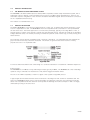
The MSM400 is an advanced Microprocessor based, HART compatible, versatile slurry measurement system, with a
wide range of built-in display, control and alarm function options. The Menu driven programming is simple to use,
and allows complete configuration of the unit from the external membrane keypad. Sensor and electrical connections
are in a separated terminal housing.
This manual is for Software Version 1.1
1.2
PRODUCT DESCRIPTION
The Mobrey MSM400 is a microprocessor based electronic control unit. It operates with sensors mounted in a pipe
section or suspended in a tank. The MSM400 monitors the suspended solids concentration in the liquid between
the two sensor faces. The normal application is to monitor this percentage, typically in the range 0.5% to 15%, to
provide signals for a plant control system to operate the slurry transport process. Typically this might be to desludge a
sewage settlement tank, or in mineral processing to maintain the percent solids of china clay, or similar, moving on to
further refiners.
The technique used to measure suspended solids is ultrasonic attenuation. As suspended solids pass between the
gap in the sensor faces they scatter the ultrasound. The amount of signal that the sensor receives is inversly
proportional to the % of suspended solids.
To allow accurate measurement over a wide range of % solids the attenuation is measured at 2 different frequencies.
Control signals :
The MSM400 has a 4-20mA, 2 relays and analogue output, typically 4-20mA, The MSM400 can control a desludge
operation using a combination of measured % solids, external trigger and internal timers.
The unit is also HART compatible, to feed in to digital control systems using HART protocol.
A typical application would be with the sensors mounted in a discharge line from a refiner or settlement tank. The
relay in the MSM400 would be used to stop the de-sludge cycle when the liquor runs clear, switching at typically
about 4-5% suspended solids.The ultrasonic technique has an advantage over some techniques in that it is largely
unaffected by fouling of the sensor face.
IP258
5
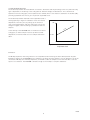
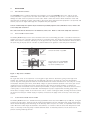
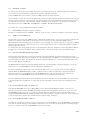
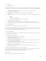
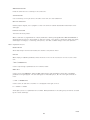
SLURRY CHARACTERISTICS
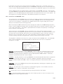
The relationship between the measurement of ultrasonic attenuation and the percentage solids of a particular slurry
type is dependent on the density of the slurry particles and their average size distribution. This is known from
experience for most slurry types, and is expressed as a number, which is the ultrasonic attenuation in deciBels (dB),
per mm gap between sensor faces, per one percent suspended solids.
The relationship between attenuation and suspended solids is
shown graphically in Figure 2. Calibration of the unit involves
adjustment of the zero point, by setting up the sensors in
clean liquid (supernatant), and then setting the slope of the
straight line graph, either according to past data or from site
samples.
In the memory of the MSM400 there is information on various
slurry types, to enable simple initial set-up. More accurate
adjustment can then be made once site samples have been
taken.
Attenuation
(dB)
pe
Slo
Zero Ref
% Solids
Figure 2 :
Ultrasonic Attenuation versus
Suspended solids
Calibration:
The Mobrey experience with using ultrasonics for suspended solids monitoring has been developed over 25 years.
Calibration systems for the MSM400 use this experience, allowing the plant operator to choose whether to set up the
unit based on Mobrey site and slurry experience, or whether to take site samples to fine tune that data to suit the
specific site conditions. The MSM400 is versatile enough to allow simple or complex calibrations.
IP258
6
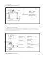
2.0 SENSOR TYPES
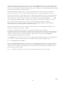
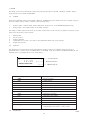
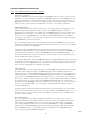
2.1 SUSPENDED SENSOR TYPE MSM433
20
Material :
Gap size :
316 Stainless steel
100mm, 150mm, 200mm,
300mm,
450mm
(others on request)
Cable :
Dual twin-axial
Max. Pressure :
105 kg/cm2 (103 bar)
Temperature range : -40°C to + 70°C (others on
request) Refer to Sensor
safety data for intrinsically
safe systems
R¾" (BS21:1973)
¾" BSPT
61
Standard gap = 150mm
22
102
Specify gap
50 to 450mm
30
30
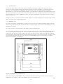
Figure 3 : MSM433 Sensor and Specifications
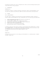
2.2
MOBREY PIPE SECTION SENSORS
The Mobrey pipe section is used as part of a pipeline transporting the slurry to be monitored. Each pipe section
contains two sensors, installed with their faces accurately aligned and flush with the pipe inner wall, to avoid any
excessive slurry or grease build up on the faces.
455
Material pipe section :
Material sensors :
Drain fitting :
Mounting connection :
Flanges :
Retaining nut
Max pressure :
Temperature range :
Location pin
Sensor cable :
Cable length :
Cable junction box :
Malleable cast iron epoxy coated
316 stainless steel
1" NPT
In line installation
DN100, DN150, DN200 to BS4772
(others on request)
10 Bar (PN10)
-40°C to +70°C(for T6), +120°(for T5)
(Others on request)
Refer to Sensor safety data for intrinsically
safe systems
Oil hose protected on pipe section,
Screened twisted pair
7m dual twin-axial from junction box (others
on request)
IP65 aluminium alloy
'O' ring
Sealing
face
Figure 4 : MSM448 Pipe Section Sensors
IP258
7
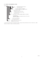
2.3 SENSOR TYPE NUMBERING SYSTEM
MSM *** * *** * * / *
No.
- Indicates special requirement
i.e. 1 - with PN16 flanges
7
D
V
P
T
000
A
N
433
448
- 7m cable supplied as standard
- Customer defined upto 100m (must be
clearly stated on order
- Spray valve (pipe section only)
- No spray valve (pipe section only)
- 433 tank mount
- Sensor size i.e. 100, 150, 300, 450mm as standard
for tank mount
100, 200, 150mm as standard for pipe section sensor
(others on request)
- Intrinsically safe (ATEX)
- Non Intrinsically safe
- Sludge blanket tank mount sensor
- Sludge pipe mount sensor
In intrinsically safe systems, the maximum length of integral cable permitted by the sensor certification is 50m.
Additional extension cables are however permitted.
IP258
8
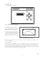
3.0 CONTROL UNIT
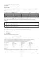
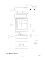
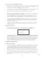
3.1 MSM400 DISPLAYS AND KEYPAD
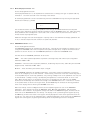
Figure 5 : MSM400 keypad and LCD display
The MSM400 is wall mounted: the lower
section of the housing is for cable connections,
and the upper part has the 4 line LCD and
keypad controls. The whole unit is IP65.
Typically the display will show as in Figure 7,
the top line shows whether the programme lock
is open together with the time display. The
actual value is displayed in the centre. The
attenuation figure in decibels is on the bottom
line.
Display 1
03.09
1
2
4.6 %
0
RL1
RL2
46.3dB
Display 3
Display 2
Figure 6 : Typical MSM400 liquid crystal display
Additional flags on the display show the status of the two relay outputs, RL1 and RL2 ,and of the digital control
inputs into the MSM400.
KEYPAD OPERATION :
There are 6 buttons on the MSM400 front panel, the four ARROWS allow navigation around the programming menu
and the " ESC" and "ENT" buttons allow movement from one screen to the next. By pressing "ESC" repeatedly, the
screen will always return to the normal display as shown in Fig 7. Movement through the menu structure using the
arrows is shown by the titles being "highlighted", ie reversed to showing white letters on a black background. The LCD
is backlit for operator convenience. (This can be turned off if required).
IP258
9
3.2
SPECIFICATIONS--MSM400
Housing
ABS with polycarbonate lid, IP65
External dimensions
256.5 wide, 236.7 high, 95.0 deep, including wall mounting brackets
Cable Glands
3x 16mm holes and plastic glands supplied
3x 20mm holes and plastic glands supplied
Weight
2 kg
Wall Mounting holes
6 off Diam 5.0mm (See Drawing Section 4.5)
Power supply options
115 V a.c. (±15%) 50 / 60 Hz
230 V a.c. (±15%) 50 / 60 Hz
or 24 V d.c. (15 to 30 Volts)
Power consumption
a.c. 10VA
d.c. 6W
Fuse (F1)
200 mA (T) 5 x 20mm
Current Output
0-20 or 4-20 mA selectable,
maximum load 1KΩ (at 22mA)
maximum applied voltage 48v d.c
HART
HART digital communications, Two HART internal test terminals provided.
Relay Outputs
2x SPCO Relays, rated 5 Amps at 250 V a.c. Resistive
DC Power Output
24V DC for external sensors such as Mobrey Electrosensor
Sensor connections
Terminals for Mobrey sensor Tx and Rx cables, each 2 cores and screen
Trigger inputs
Unit accepts two 5V d.c.trigger input signals. 5V d.c. provided - compatible
with Mobrey Electrosensor
Terminals
Max. cable size 2.5mm2
Ambient temperature
-30°C to 55°C
Max Altitude
2000m
Max Humidity
95% RH
Electrical Safety
Conforms to EN61010-1
Installation Category
Cat III 132V a.c. Max., Cat II 264V a.c. Max.
Pollution Degree
2
EMC
Complies with EN61326 (Industrial level)
IP258
10
4
INSTALLATION
4.1
PRELIMINARY CHECKS
The MSM400 system is normally supplied in two packages, one for the MSM400 Control Unit and one for the
sensor, whether it is a pipe section or a tank sensor. Take care in handling the pipe section. In particular do not
damage the cable or the hose protection for the cable where it enters the sensors. Before installation check that
there has been no damage in transit, particularly to the sensor cables. Check that the equipment is as specified, and
that the pipe section length and flanges are compatible with plant pipework.
Sensors in intrinsically safe systems may be mounted in potentially explosive areas ("hazardous areas"). Refer to the
sensor safety data section 2.4.
The control unit must be mounted in a non-hazardous ("safe") area. Refer to control unit safety data section 3.3.
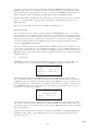
4.2
PIPE SECTION INSTALLATION
The Mobrey MSM448 pipe section sensor should be same size as surrounding pipe work. It should be installed in a
straight section of line, if possible, with the sensors in a horizontal plane. This avoids the sensors being covered with
debris at the bottom of the pipe, and being in an air gap at the top of the pipe. Particular attention must be paid to
the positioning of the pipe section in relation to pressure reduction or agitation of the slurry to be monitored :
Sensors horizontal in pipe OK
Pipe line
Sensors vertical in pipe NOT OK
Sludge settles on bottom sensor
Top sensor probably in air
Pipe line
Figure 7 : Pipe sensor orientation
WARNING:
Air or gas that comes out of suspension in a slurry gives a high ultrasonic attenuation, giving a false high solids
reading. The installation must maintain the full hydrostatic pressure in the slurry up to the pipe measurement
section. Any unnecessary pressure reduction should be avoided. This means avoid free fall of the slurry into a sump,
avoid pumps and partly open valves, avoid abrupt changes of pipeline diameter upstream of the sensor pipe section
installation point. If possible position the sensors directly at the outlet of the tank, low down, so that the full
hydrostatic head is maintained on the monitored liquid. However, it may be necessary to remove the sensors for face
cleaning later, so isolation valves are desirable. The Mobrey Sensor pipe is supplied with a flushing spray nozzle,
which directs a supply of water at the sensor faces. This is a useful cleaning procedure, avoiding the need to remove
the sensors from the pipe. A water supply is required, connected to the purge nozzle on the top of the sensor pipe
section.
4.3
SUSPENDED SENSOR INSTALLATION
The Mobrey MSM433 sensor is available with the gap between sensor faces from 100 mm up to 450 mm, for higher
sensitivity to light slurries. These sensors are usually mounted directly into the settlement tank, at pre-selected levels
above the tank discharge outlet. Mounting can be vertically down on a piece of conduit, or suspended on the sensor
cable. Whilst the conduit might be attached to the tank wall, it is normal to have the sensor well away from the wall
itself, to avoid any non moving slurry or "dead" settlement areas. It should be possible to lift the sensor out for
periodic cleaning and/or rag removal.
IP258
11
4.4
SENSOR CABLES
The ultrasonic drive signals on the sensor cables are normally at 1MHz and 3.3MHz. The cables are a special
construction of two separately screened twisted pairs, designed to meet electromagnetic compatibility regulations.
The cables can be extended up to 100 metres, but should use the same cable type, available from Mobrey
Measurement. (or consult factory for alternative vendors). The certification for intrinsically safe systems requires that
cable joins should be in enclosures rated at least IP20 and suitable for the intended enviornment and that the wiring
should withstand a test voltage of 500V rms to earth. The electrical parameters of the cable used must conform to
Table 1 in section 2.4.
Twisting the cables on installation should be avoided. Cable runs should be separated from any high voltage or mains
cables, to avoid crosstalk or switching transients.
4.5
CONTROL UNIT
The control unit housing is rated IP65. It is suitable for mounting outside, but this should be above any flood level,
away from any overflow water path, and away from direct sunlight. Internal sensors turn the LCD backlight off if the
temperature is excessive.
The control unit must not be mounted in areas where an explosion hazard exists.
It is not necessary or advisable to remove the lid to the upper part of the box, containing the LCD and keypad.There
are no user serviceable parts inside. The control unit must not be modifed in any way. The keypad and LCD are
linked to the lower electronic pcb by a ribbon cable at the left hand side of the upper housing. Mounting brackets
for wall mounting are provided, and these should be attached to the rear of the housing using the self tapping screws
(also provided).The brackets are then used to wall mount the MSM400, using the six mounting holes available.
Dimensional information is shown below:
203.5
Internal wall mounting holes
33.35
80.0
224.2
236.7
100.0
104.2
12.5
4.2
6 off mounting holes Ø
5.0
226.5
241.5
256.5
Figure 8 : MSM 400 Control Unit Dimensions
Note that the weight of the MSM400 is 2Kg. To conform with safety requirements the wall should be capable of
supporting 4 x this weight, ie. 8Kg. 5mm diameter steel screws should be used.
IP258
12
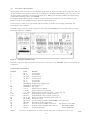
4.6
ELECTRICAL CONNECTIONS
All field wiring connections are accessible by removing the lower lid, which is secured by two screws. Note that it is
the responsibility of the installer to observe all local regulations and approval requirements, and to use cable to suit
the environmental requirements of the particular application. Obtain and check any hazardous area work permits
required before applying power to the MSM400.
The diagram below shows the layout of external connection terminals: all terminal blocks are suitable for wires
0.5mm2 to 2.5mm2 (26-12 AWG). Insulation should be stripped back 7mm.
Ensure wiring is suitable for the load current and the insulation is suitable for the voltage, temperature and
environment of the installation.
Note that in intrinsically safe systems, apparatus connected to the MSM400 must not be supplied from a voltage
greater than 250V rms or 250V DC.
FUSE
200mA
K7941
Figure 9:
Connection Terminal Layout
Note that not all of the labelled terminals are functional in this version of the MSM400. The functions available are
listed below :
CONNECTION DESCRIPTIONS :
Terminal
1
2
3
4
5
6
7
8
10
16
17
18
19-21
22-24
25
26
27
28
29
30
31
NOTE 1
Label
RX A
RX B
RX SCN
TX SCN
TX A
TX B
TRIGGER 0V
TRIGGER D1
TRIGGER 5V
I out Io
I out 0V
I out 24V
RELAY 1
RELAY 2
DC out 24V
DC out 0V
DC in 24V
DC in 0V
Mains L
Mains N
Mains E
Function
Sensor Cable
Sensor Cable
Screen for 1+2
Screen for 5+6
Sensor Cable
Sensor Cable
Ground ref for Trigger inputs
Digital input No 1
5 V output
Current output (4-20mA)
Current output zero ref terminal
Current output 24 V DC loop power : refer to Fig. 10
NC-C-NO Relay output terminals for Relay 1
NC-C-NO Relay output terminals for Relay 2
Output of 24 VDC for powering external devices.
Ref for DC output
Positive supply at 24VDC to the MSM400--ie DC power input
Ref terminal for DC supply input
AC power input 115/230V, Live terminal
NB: SELECT 115 or 230V
AC power input 115/230V, Neural terminal
ON SWITCH ABOVE
Protective Earth (PE)
THESE TERMINALS
The sensors are symmetrical, so either of the two cable pairs can be chosen as "Tx" or "Rx
13
IP258
SENSOR CONNECTIONS
The sensor connections are on the left side of the terminal enclosure.
Each sensor has two screened twisted wire pairs, either as one dual pair cable, or two separate pairs
One pair is connected to the TX (transmit) group and the other to the RX (receive) group. The sensors are
symmetrical so either of the pairs can be chosen as TX or RX. The two cores in each group are connected to A and
B, the polarity is not important. Each screen connection, normally coloured green, is connected to the group’s SCN
terminal. Cable screens must not be earthed at any other point.
The un-screened length of the cores should be as short as possible, to prevent crosstalk, but in any case no longer
than 30mm.
RELAYS
The relay NC-C-NO labels represent the relay terminals in the de-energised state.
HART CONNECTIONS AND JUMPER SETTINGS
There are two clearly labelled HART Test Points, labelled A and B. These test points are for connection of a HART
Hand Held Communicator, to provide a local interface to the MSM400 if required. Above terminal blocks 7-12 there
is a plug selector labelled PL1.
The normal position is with the plug shorting out the left hand pins. In this case, the external 20 mA loop must have
at least a 250 ohm impedance to enable HART communictions. With the plug in the central position, the MSM400
itself provides this load in the 20 mA loop. The right hand position enables HART communication when there is no
external loop connected by connecting a 270 ohm resistor across the current output. (See Appendix D).
NOTE:
The 20 mA output will not function correctly when the link is in this right hand position, so replace it in position 1 or
2 after use!
CURRENT OUTPUT
The current output may be connected in loop-powered mode or internally powered mode.
See connections in Fig 10 below.
In Loop-powered mode an external power source is required. A minimum of 2.5v is required across terminals 16 and
17 for correct operation. The external voltage should not be more than 30v.
Note that the current output must not be routed through hazardous areas unless protected by an additional I.S.
barrier.
Terminal Number
Figure 10 : Alternative current output configurations
IP258
14
TRIGGER INPUTS
There is trigger input D1. This can be used to control desludge and other functions see programming section. The
digital trigger input is connected as shown below:
5V
10
D1
8
0V
7
A voltage greater than 2V on Terminal 8 (D1) causes trigger input 1 to be active. This can be achieved by
connecting to terminal 10 (5V) via an external switch or relay. The maximum voltage should not exceed
28V.
24V
24V
25
0V
MES*AI OR
ELECTRO SENSOR
26
D1
8
0V
0V
7
The trigger input is also compatible with the MOBREY Electrosensor sensors and head amplifiers. A 24V output is
provided for this purpose. Typically this allows complete control of the desludge cycle by using a second sensor
(Electrosensor) to start or stop the cycle. The terminal connections are shown above (note: it is important that the two
0V connections on terminals 7 and 26 are linked).
NOTE : When connected to these terminals the electrosensor sensors and head amplifiers MUST NOT be
installed in explosive atmospheres.
MAINS SUPPLY
The unit can be powered either by 24V DC or by mains AC power. If both are connected, the unit will select the
supply producing the highest internal 24V power rail. Select the AC Voltage as 115V or 230V using the selector slide
switch above the AC line terminals.
Although the MSM400 meets all European standards for surge immunity on power and signal lines, it is
recommended that lightning suppressors are fitted if local conditions make this advisable. Units manufactured by
Telematic are suitable.
SAFETY PRECAUTIONS
A switch or circuit breaker should be installed in close proximity to the instrument, and labelled as such.
The unit must be earthed using the protective earth terminal 31.
INITIAL POWER UP
The unit will initially display the software revision number on Power up, and then revert to the standard display
screen, showing a measured slurry/sludge density. If the sensor is in air, then this value will be high -the unit is
effectively at full scale deflection.
15
IP258
5.0
PROGRAMMING
5.1
The operation of the MSM400 is controlled by means of programmable parameters. These are stored in
memory and may be set by the user to define variables such as calibration scale factors, set points, and modes of
operation. The parameters are accessed using the keypad, by means of a menu system as shown below. (Parameters
may also be edited remotely using the HART protocol. See Appendix N). For a full listing of the menu structure refer
to Appendix A1.
5.2
Navigation in the menu system
From the main display, pressing any key except ESC will enter the menu system. The top level menu contains the list
of available menu items:
TOGGLE RUN
CALIBRATION
SETUP
MONITOR
To move up and down the list, use the UP and DOWN arrows until the required menu item is highlighted, then use
the ENT or RIGHT arrow key to select it. The presence of additional menu items off the screen is indicated by up
and down arrows on the right hand side of the display
The next level of the menu is then displayed and the required option can again be selected as above.
Continue until the required parameter is displayed and select it using the ENT key. (Note that menu groups are in
upper case letters, parameters are in upper and lower case.)
The parameter may now be modified. Numeric values are edited one digit at a time, the LEFT and RIGHT arrows
select each digit by highlighting them and the UP and DOWN arrows increment and decrement each digit. Some
parameters e.g. “PV Units” are in the form of a list. These are edited in a similar way, selecting with the RIGHT arrow
and using the UP and DOWN arrows to scroll through the list
When the displayed value is correct, press the ENT key to store it.
Scrolling
When a parameter is displayed but no digit is selected, the UP and DOWN arrow keys will scroll to the next parameter
in numeric order. This provides an alternative method of accessing parameters without using the menu facility.
Example: Relay 1 set point programming.
To programme the relay, follow the simple steps shown below;
1.
2.
To alter any menu option the padlock icon in the top left of the display must be open. This is done using the
TOGGLE RUN menu.
To access TOGGLE RUN from the normal display, press any key except ESC to display the main menu. The
down arrow (↓) shown on the screen indicates that there are further options. (including MONITOR)
MAIN MENU
TOGGLE RUN
CALIBRATION
SETUP
0
0
↓
IP258
16
3.
Use the down arrow key (ß) to highlight the TOGGLE RUN option and select it using the “ENT” key. The
TOGGLE RUN screen is then displayed:
TOGGLE RUN
4.
5.
6.
7.
8.
9.
10.
To open (or close) the padlock press ENT as required. Press ESC to return to the main menu.
Programming is now enabled.
From the Main Menu screen, use the down arrow key (ß) to highlight the SETUP option and select it using
the “ENT” key
In the SETUP menu use the ß key to highlight the OUTPUT option and select it.
In the OUTPUT menu use the ß key to highlight the RELAY option and select it.
The parameters associated with the relays are now shown.
In the RELAY menu highlight the RELAY 1 MODE and select it using the “ENT” key.
0
0
Relay 1 Mode
Set Point
11.
P410
Press the right key (Þ) to highlight the option.
0
0
Relay 1 Mode
Set Point
12.
13.
14.
P410
Note; with the option highlighted pressing the up and down arrows scrolls through the available options.
With the set point option highlighted press ENT to select. The highlighting now disappears.
Pressing ß will display the next item in the menu, RL1 On Point.
0
%
0
P411
RL1 On Point
0.00
15.
This is a numeric parameter, therefore pressing Þ highlights the first digit that can be edited.
RL1 On Point
000.00
16.
0
0
0
%
0
P411
Select the digit to be edited by pressing Þ as necessary.
RL1 On Point
000.00
0
%
0
P411
IP258
17
17.
The value of the digit may now be incremented or decremented by pressing ⇑ ⇓.
RL1 On Point%
003.00
0
0
P411
18.
Press ENT to store the value. The highlighting will disappear. If an invalid number is entered then the display
will revert to the last valid value.
19.
The relay off point is programmed in the same way (all other numeric parameters are programmed in a similar
way).
When programming is complete, return to the TOGGLE RUN menu and close the padlock.
Note; any programme changes will not alter the outputs, which remain frozen,
until the TOGGLE RUN padlock has been closed.
20.
21.
5.3
DIAGNOSTIC PARAMETERS
Apart from the user-settable parameters described above, there is another set of diagnostic parameters, which display
measured or calculated data to analyse and optimise system performance. These have the prefix “D” and cannot be
modified.
5.4
EX-FACTORY SYSTEM FEATURES
The MSM400 Control Unit is supplied with default parameters that allow basic initial operation. The values and
descriptions are listed in appendix two of this manual.
6.0
CALIBRATION
There are several methods for calibrating the MSM400, AUTOCAL and MANUAL ENTRY, these together with some
important basic principles are explained below. Calibration always comprises two stages, zero setting and span setting.
Zero setting calibrates the system so that the control unit indicates 0% solids in clear liquid.
Span and lab value setting calibrates the system to monitor suspended solids accurately.
The recommended, simplest and most accurate method for calibrating the MSM400 is by using the AUTOCAL
procedure, which is explained below.
6.1
ZERO SETTING
INITIAL ZERO
The MSM400 has the facility to warn the operator that the sensors require cleaning. The first zero calibration will be
stored in initial zero reference parameter, “Init zero ref”. Future zero calibrations are compared with this value and
any significant change will produce a warning message like the one shown below.
SET ZERO
In clear liquor
press ENT to set
Sensor dirty
0
0
The actual difference required to produce this warning is programmed in dirty point (SETUP – ENGINEERING
– SENSOR LIMITS – Dirty Pt). The default value is 0, which disables this feature. To enable the feature it is
suggested that a value of approximately 6 dB is entered.
Note: this warning feature is not active until the first zero calibration has been carried out.
To reset or clear initial zero value, ‘0’ must entered in Initial zero reference parameter (CALIBRATION – MANUAL
ENTRY – ZERO REF – “Init Zero–1MHz” and “Init Zero–3MHz”, P123 & P124).
IP258
18
6.2
RECHECKING ZERO
It is recommended that the zero is checked regularly. The frequency of re-calibration is dependent on the process.
However, it is suggested that this be done at least every 6 months.
CALIBRATION METHODS
AUTO CAL
6.3
AUTO CAL - ZERO SETTING PROCEDURE
AUTOCAL is a simple step by step calibration routine in which the user is guided through the calibration process by a
series of user friendly screens. AUTOCAL is the recomended calibration proceedures.
The attenuation of the ultrasonic signal in dean liquid varies slightly from sensor to sensor. For optimum system
accuracy it is important to set up this zero loss accurately. When the system has been installed, immerse the sensors
in the clearest liquid available. If this is not practical, choose a point in the cycle when the liquid in the gap between
sensors has the lowest possible % suspended solids. For example on sewage treatment plants wash water would be
acceptable.
Firstly enable access using the “TOGGLE RUN” command in the MAIN MENU.
Highlight the CALIBRATION option in the MAIN MENU by pressing the down arrow key.
MAIN MENU
TOGGLE RUN
CALIBRATION
SETUP
0
0
Press ENT.
CALIBRATION
AUTOCAL
MANUAL ENTRY
Max %
0
0
Highlight the AUTOCAL option by pressing the down arrow key, and press ENT.
CALIBRATION
AUTOCAL
MANUAL ENTRY
Max %
0
0
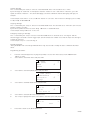
Highlight the SETZERO option and press ENT. The following will show on the display.
CALIBRATION
SETZERO Max %
SETSPAN
LAB VALS
0
0
Follow the instruction, the display will show the following
SET ZERO
In clear liquor
Press
⇒
0
0
IP258
19
The display will show the following.
SET ZERO
In clear liquor
please wait
0
0
After a few seconds the display will show the following.
SET ZERO
In clear liquor
Press ENT to set
23.1dB
26.2dB
0
0
The two dB values at the bottom of the screen are the zero values for the operating frequencies of the sensor
(1MHz and 3.3MHz).
Once the ENT key is pressed the zero is set. All zero reference data is now saved together with the
date of zero calibration. The screen now gives the option to re-do the zero setting or return to the AUTOCAL menu.
SET ZERO
Zero is now set
ESC to finish
ENT to re-do
6.4
0
0
AUTOCAL - SPAN SETTING PROCEDURE
The span setting measures the signal received from a representative sample of sludge. Later when the sludge is
analysed and the results entered in the control unit the system automatically calculates the correct calibration factor
(SLOPE).
If suitable slurry is not available an approximate calibration can be done using slurry types chosen from a list. This
proceedure is detailed in Sectiono 6.10.
At least one span measurement must be taken. However, for better accuracy it is possible to take up to three span
measurements and the MSM400 will calculate the average value.
Return to the AUTOCAL menu and highlight the SETSPAN option.
CALIBRATION
SETZERO Max %
SETSPAN
LAB VALS
0
0
Press ENT. The following is shown on the display
SET SPAN
In sample 1
Press
⇒
0
0
Now allow the normal or thickest (thickest is best) sludge which is to be metered, to cover the MSM400 sensor.
Press the ⇒ key the display will show.
SET SPAN
In sample 1
please wait
0
0
IP258
20
After a few secnds the display will show the following.
SET SPAN
In sample 1
Press ENT to set
33.6dB
44.2dB
0
0
The bottom line of the display shows the attenuation caused by the sludge. During a desludge these readings will
fluctuate due to random variations in the sludge density. When the readings are reasonably stable press ENT at the
same time that a sample is taken. This will store the reading from the sensor.
SET SPAN
Span1 is now set
ESC to finish
↓ for Span2
0
0
Press the down arrow key to access the sample 2 and sample 3 screens (if required).
Repeat the above procedure for samples 2 and 3. The span is now set and ready for input of laboratory result (see
later). When the sample procedure is complete press ESC until the normal display shows.
For best accuracy the three samples should be taken over a period of approximately 2 to 3 minutes.
The samples should now sent for laboratory analysis to establish the actual suspended solids content.
When the laboratory analysis results are available, the span calibration can be completed by entering the solids
content (in % Solids) into “Lab Value 1” (P150).
If required, an estimated value can be used until the laboratory analysis results are available.
Note:
6.5
Each time SPAN 1 is set the other two SPAN and LAB values are cleared and are not used
until new Span2 and Span3 calibrations are carried out. The MSM400 calculates the
average of all the valid span calibrations (a valid span calibration is one which has both a
span ‘N’ and lab val ‘N’ value). The calibrations must be carried out in numerical order
i.e. Span 1, then Span 2 and then Span 3. These values should be carried over a short
period of time i.e. 2 to 3 minutes.
AUTO CAL LAB VALUES
To complete the AUTO CAL the samples must now be analysed and the results entered into the lab value menu.
Access the LAB VALS menu by highlighting this option in the AUTOCAL menu and pressing ENT.
LAB VAL
LabVal 1
LabVal 2
LabVal 3
0
0
Highlight the number of the LabVal to be entered and press ENT
LabVal 1
LAB VAL
%
0
0
0.00 P150
Highlight the digit to be edited by pressing left or right arrows. To change the LabVal use the up and down arrows
until the required value is showing, then use left or right arrow to move on to next digit. The units of this parameter
are always % suspended solids. When the correct value is displayed press ENT to store the value. Repeat this step to
input LabVal 2 and LabVal 3 if required (please note that better accuracy is achieved if all three samples and
corresponding LabVals are entered). Press ESC until the normal display shows.
It is important to note that until the LabVal (1,2 or 3) are entered the system will use the default value of
attenuation for the calibration.
IP258
21
6.6
MAXIMUM % SOLIDS
To complete the calibration and to enable the system to automatically select the optimum frequency of operation., it
is necessary to set the maximum % solids that the system is required to measure.
In the AUTOCAL Menu, select ‘Max % Solids’ (P 160) and enter the value required.
If the maximum % solids are low then the system will choose the higher operating frequency (3.3 MHz). This will give
the best possible resolution. If the maximum % solids are higher than can be measured at 3.3 MHz then the system
will automatically select the lower frequency (1 MHz). The figure for the maximum % solids that can actually be
measured can be seen in MONITOR - DIAGNOSTICS - SENSOR – Max Measurable (D861)
The control unit is now calibrated and ready for operation.
6.7
CALIBRATION- Alternative calibration methods
Calibration is normally done via AUTOCAL. However, in special cases, if required, calibration can be done manually.
6.8
ZERO SETTING PROCEDURE
Firstly enable access using the “TOGGLE RUN” command in the Main menu. See section 5.2. Next, ensure that the
frequency of operation corresponds to the frequency of the sensor by checking parameter D860 located in
Monitor\Diagnostics\Sensor\Frequency. If necessary it can be changed. The relevant parameter is “Frequency” (P630)
located in Set up\ Engineer\. When the sensor is in “clear” liquid note the value of “Attenuation (D852) located in
Monotor\Diagnostics\ Sensor.
To complete the zero setting, enter this value in the appropriate “Zero ref” parameter, located in Calibration\ Manual
Entry\Zero ref.. “Zero ref A” (P120) is used for 1MHz sensors, “Zero ref B” (P121) is used for 3.3MHz sensors.
6.9
SPAN CALIBRATION/GRADIENT METHODS
There are three alternative ways of setting the gradient relationship between the measured attenuation and the %
solids displayed (See Graph shown in Figure2). It is recommended that if AUTOCAL is not used then the Initial Setup
should use Method 1: when later, figures are entered according to Methods 2 or 3, these automatically take priority
over an original Method I calibration.
The First alternative method uses previous Mobrey experience of slurries/sludges, and the slurry type is chosen by
name from a list. The MSM400 then uses the appropriate calibration line.
The Second alternative method uses actual site samples, and as such it is usually the most accurate calibration
method. When the MSM400 reading is stable, a sample of slurry is taken for Lab analysis, and the attenuation
measured at that time is recorded/entered in the MSM400 memory. Later the Lab result is also entered into a
different location in the MSM400 memory, and the microprocessor computes the relationship.
The Third alternative method uses a known mathematical value of attenuation versus suspended solids for the slurry
to be monitored from site experience on other tanks or other installations with the same sensor arrangement and
slurry.
6.10
CALIBRATION METHOD 1-SLURRY TYPE
Enter the CALIBRATION option on the MAIN MENU screen. Then ENTER ‘MANUAL ENTRY’. There are four
selections possible here. Select SENSOR\ Sensor Gap and enter the space between sensor faces, in mm. This tells
the MSM400 how big the sensor is, to relate it to memory figures of attenuation. Select SLUDGE TYPE (access
through CALIBRATION, MANUAL ENTRY, SENSOR menu) and for Method I calibration select one of the listed types
to suit the application. The unit will now work with this typical sludge calibration.
6.11
CALIBRATION-METHOD 2-SAMPLES
This Method of calibration offers the highest accuracy (and is used by AUTOCAL), since the MSM400 is set up based
on actual site sample analysis. It does therefore require quite a lot of site work in taking samples, and analysing the
solids %, to enter this later into the MSM400 microprocessor memory.
IP258
22
Under stable operating conditions, the objective is to record the MSM400 attenuation figure, and immediately take a
sample of the slurry present between the sensor faces.This is then analysed in the lab, to derive the solids %, and
this % value is later linked to the previous ultrasonic attenuation. The objective is to take three separate readings and
samples, which are averaged by the Microprocessor.
Preferably the readings should be taken for a slurry concentration that Is as high as possible, to give the best
accuracy for the slope calculation. The three readings are date coded, and can all be separately inspected.
Ensure that the frequency is correct and that access is enabled as above. With the sensor in a stable representative
slurry, note the value of the relevant “Span dB” which is the attenuation due to the suspended solids. This is the
total attenuation minus the zero ref and is available in two parameters, Span dB @ A MHz (D854) for
1MHz
sensor and Span dB @ BMH2 (D855) for 3.3MHz sensors. They are located in Monitor \ Diagnostics \ Sensor.
At the same time take a physical sample of the slurry for laboratory analysis by drying and weighing.
Now enter the value of “Span dB” recorded, in the relevant “Span I @ 1MHz” (P130) or “Span I @ 3MHz”
(P131) parameters. (accessed via Calibration / Manual Entry / Span)
When the laboratory analysis results are available, the span calibration can be completed by entering the solids
content (in % Solids) into “Lab Value 1” (P150). (If required, an estimated value can be used until the laboratory analysis results are available.)
For improved accuracy up to three samples can be taken. These should be taken at roughly the same time and the
“Span dB” noted for each one. The values are entered into the relevant Span 1, Span 2, Span 3 and Lab Value 1,
Lab Value 2, and Lab Value 3 (accessed via Calibration / Manual / Entry / Lab Values). The MSM400 will
automatically average as many values as are entered.
The MSM400 stores the calculated value of the slope in 0858 (1MHz) and D859 (3.3MHz) It is recommended that a
note is made of this value. Note that the value of the frequency not being used is displayed as zero.
6.12
ATTENUATION VALUE-METHOD 3
Select the CALIBRATION /Manual Entry / Sensor to access the dB FACTOR value. This is the attenuation in dB per
percent solids for the size/type of sensor and the slurry in use. Typically this data would have come from another
installation of the same type, or previous data on this installation, read from the Diagnostic Display Data screens.
Enter the numerical value required.
NB:
It Is advisable to recheck the zero setting on the plant periodically (Every 6 months at least).
IP258
23
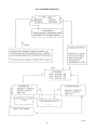
7.0 PROGRAMMING THE MSM400 FUNCTIONS
DUTY (MODE)
DESLUDGE MODE.
There are several methods of starting, stopping, overriding and stopping early a de-sludge operation. The desired
options can be selected in the SETUP – DUTY (Mode) – DESLUDGE menu. The following table explains the various
options.
(PV = process value i.e. % suspended solids)
Start on
PV above level*
Digital i/p 1 low ***
Time
Stop on
PV below level**
Digital i/p 1 low ***
Max Time
Stop if
PV below level**
Digital i/p 1 low ***
Do not start if
Digital i/p 2 low****
Normally relay 1 is used for control purposes. Relay two is normally the alarm relay.
If selected, the desludge operation defaults to “Start on”– Time, “Stop on”– PV below a level.
“Do not start if” and “Stop if” are set to “none” (i.e. in default conditions these do not affect the desludge
operation).
*
**
***
****
Above level is above Relay 1 or 2 On Point
Below level is below Relay 1 or 2 Off Point
Digital input 1 low for 1 sec, 2 sec, 5 sec, 10 sec, 15 sec, 20 sec, 30 sec, 40 sec, 50 sec, 60 sec, 90
sec, 120 sec, 180 sec, 240 sec & none
Digital input 2 low for 1 sec, 2 sec, 5 sec, 10 sec, 15 sec, 20 sec, 30 sec, 40 sec, 50 sec, 60 sec, 90
sec, 120 sec, 180 sec, 240 sec & none
The min and max times described in Set point operation also apply in de-sludge mode.
If it is required to set the control unit up to Start on Time then 4 parameters can be set up:1.
2.
3.
4.
(Start
Start time 1
Time interval 1
Start time 2
Time interval 2.
time 2 and interval 2 default to not used.)
The time interval indicates the interval between de-sludges.
Start time 1 indicates the time of the first de-sludge operation. A de-sludge will always happen at this time each day
independent of the time interval.
Start time 2 indicates the time of another fixed de-sludge time.
If either of the start times are set to 0:00 then the interval associated with that start time is not used.
If both of the time intervals are set to 0:00 then de-sludge only occurs at the start times.
The following table shows the default and limits of the time desludge operations.
No. of operation.
Start time 1
Time interval 1
Start time 2
Time interval 2
Set in
(hrs & mins.)
hh:mm
hh:mm
hh:mm
hh:mm
Default value
(hrs & mins)
8:00
1:00
0:00
0:00
Max value
(hrs & mins)
23:59
24:00
23:59
24:00
Example:
In this example it is required to control the desludge operation as follows: Relay 1 will be used to open a discharge
valve. Desludge cycles should start at fixed intervals. Each desludge cycle should stop on detection of thin sludge,
thus preventing unwanted transfer of clear liquor. The “Stop if” function will also be used to stop the desludge using
a digital input (i.e. an external trigger.). from a pump protection switch if the pump should fail. Typically in this
example the sensor is mounted close to the bottom of a primary tank or in the discharge line.
IP258
24
Starting desludge
This is controlled by the “Start on” function in the DESLUDGE menu. This should be set to “Time”.
Cycles will begin at “Start Time 1” and repeat at intervals “Interval 1” until “Start Time 2”. After this, cycles will
repeat at intervals “Interval 2”. This allows desludging to be done at different intervals during day and night, for
example.
In the example “Start Time 1” is set to 7:30 and “Interval 1” to 5 hours. This will result in desludge cycles at 7:30,
12:30, 17:30, 22:30 and 03:30
Stopping desludge
This is controlled by the “Stop on” function in the DESLUDGE menu. This should be set to “PV<level” (PV = Process
Variable, normally % solids)
Cycles will stop when the PV is less than “Relay 1 Off Point” in the RELAY menu.
In the example “Relay 1 Off Point” is set to 2%
Emergency stopping of desludge.
This is controlled by the “Stop if” function in the DESLUDGE menu. It should be set to “Ext Trig Xs” and the
external trigger connected to the D1 trigger input. (The X indicates the number of seconds the input must be high to
activate the function)
In the example “Stop if” is set to Ext Trig 2s
Related parameters.
“Relay N Max On Time” and “Relay N Min Off Time” may also be used to modify the basic commands described
above.
Programming procedure.
1.
2.
From the normal display Press any key (except ESC) to access main menu (note; ensure TOGGLE RUN
padlock is open).
Scroll down to the SETUP menu and press ENT.
SETUP
DUTY (Mode)
INPUT
OUTPUT
3.
0
0
↓
Scroll down to the DUTY (Mode) menu and press ENT.
DUTY (Mode)
PV CALCULATION
Description
Message
4.
0
0
↓
Scroll down to the Start On menu and press ENT.
Use ⇒ key to highlight the option, scroll down to the Time option and press ENT.
0
0
Start On
Time
7.
↓
Scroll down to the DESLUDGE menu and press ENT.
DESLUDGE
Start On
Stop On
Do not start if
5.
6.
0
0
P250
Press ESC to return to the DESLUDGE menu.
IP258
25
8.
9.
Scroll down to “Start time #1” and press ENT.
Use ⇒ key to highlight the first digit in the time, scroll up and down to edit the digit. Use the left and right
arrows to move to the next digit (the time is programmed in hours and minutes h : m). When the correct start
time is shown on the display press ENT.
Start Time
7:30
10.
11.
12.
13.
14.
15.
16.
17.
18.
#1 h:m
P254
0
0
Press ESC to return to the DESLUDGE menu.
Scroll down to “Interval #1” and press ENT.
The interval is the time that the control unit waits between the end of one desludge and the start of the next.
To set the interval use ⇒ key to highlight the first digit in the interval, scroll up and down to edit the digit.
Use the left and right arrows to move to the next digit (the time is programmed in hours and minutes h : m).
When the correct interval is shown on the display press ENT.
Press ESC to return to the DESLUDGE menu.
Scroll to “Stop on” and press ENT.
Use ⇒ key to highlight the option, scroll to the “PV<level” (P251) option and press ENT.
Press ESC to return to the DESLUDGE menu.
Scroll down to “Stop if” and press ENT.
Use ⇒ key to highlight the option, scroll down to the “Ext Trig Ns (P252)” option and press ENT. Where N =
the number of seconds that the digital input must be active before the control unit stops the desludge. This
value is chosen from a list by scrolling, picking the desired time and pressing ENT.
Stop if
Ext Trig 2s
0
0
P252
The times available are digital input 1 active for 1 sec, 2 sec, 5 sec, 10 sec, 15 sec, 20 sec, 30 sec, 40 sec, 50 sec,
60 sec, 90 sec, 120 sec, 180 sec, 240 sec & none.
19.
Press ESC three times to return to the SETUP menu.
20.
Scroll down to OUTPUT and press ENT.
21.
Scroll down to RELAY and press ENT.
22.
Scroll down to “RELAY 1 Mode” and press ENT.
23.
Use ⇒ key to highlight the option, scroll down to the “Desludge” (P410) option and press ENT.
24.
Press ESC to return to the RELAY menu.
25.
Scroll down to RL1 Off Point and press ENT.
26.
Use ⇒ key to highlight the first digit to be edited, scroll up and down to edit the digit. Use the left and right
arrows to move to the next digit (the off point is programmed in % suspended solids). When the correct value
is shown on the display press ENT.
27.
Return to the TOGGLE RUN menu and lock the padlock by pressing enter.
28.
The system is now in desludge mode.
IP258
26
7.1
OUTPUTS
7.2
CURRENT OUTPUT
The operation of the current output is set up by four different parameters and is always controlled by the process
variable (PV), which is normally % suspended solids. These are found in SETUP – OUTPUT – CURRENT OUTPUT.
1.
2.
3.
Lower range value (Low range val)
This is the value of PV which corresponds to the minimum current output, either 0 or 4mA
Upper range value (Up range val)
This is the value of PV which corresponds to the maximum current output, 20mA.
Alarm action
This is the value to which the current output is driven under alarm conditions and is selectable from a list.
•
•
•
4.
3.6mA
21mA
Hold (i.e. hold last reading)
For alarm conditions see the section below titled ALARM.
5.
0-20mA or 4-20mA setting (0/4-20mA)
This parameter sets the current output range to either 0-20mA or 4-20 and is selected from a list.
If required the 4-20mA can be trimmed using an external calibration meter. (For details see Section 7.8)
7.3
RELAY OPERATION
The MSM400 controller offers various options for operating the relays.
There are 2 relays that are programmable to different modes, set point operation, de-sludge, alarm and fault. The
mode of operation is selected through the SETUP – OUTPUT – RELAY – Relay Mode menu. The default mode for
Relay 1 is set point operation and Relay 2 default mode is alarm.
a) SET POINT OPERATION
It is possible to program both relays for set point operation. These are found in SETUP – OUTPUT – RELAY. The
process value (PV) controls the relays.
1.
2.
3.
4.
5.
Relay on point (RL* On Point)
This is the value of PV at which each relay will turn on
Relay off point (RL* Off Point)
This is the value of PV at which each relay will turn off
Relay minimum on time (RL* Min ON)
This is the minimum time that the relay will stay on for and this takes priority over the maximum on time.
Relay maximum on time (RL* Max ON)
This is the maximum time that the relay will stay on for.
It is important to note that this function only operates when the minimum off time is set to a non zero
value.
Relay minimum off time (RL* Min OFF)
Once the relay has turned off this is the minimum time before the relay will turn on again.
(*=1or 2 i.e. relay one or two)
If both on and off parameters are set to zero then relay is turned off.
If the on and off points are equal (non-zero) the relay is on when PV is above the set point and off when below.
If both minimum and maximum on times are set to zero (default) then they are not used.
(See also the example in “NAVIGATION IN THE MENU SYSTEM”).
b) DESLUDGE
When in desludge mode the relays operate as explained above.
IP258
27
c) ALARM
The relays can be set for alarm mode conditions by selecting the option in SETUP – OUTPUT – RELAY – Relay *
mode. See the section below titled ALARM.
7.4
ALARM
There are six different alarms in the SETUP - OUTPUT - ALARM menu. Each alarm can be set to operate a relay, or
drive the current output, or both, or neither to the following states.
1.
2.
Current output - 3.6mA, 21mA, Hold as defined in “Alarm action” in the CURRENT OUTPUT menu.
Relay outputs – The relays energise in the alarm condition
The relays or current output must be set up for alarm or fault action for this function to operate. The effects of each
alarm action are shown in the list below :
1.
2.
3.
4.
5.
Memory fault
PV out of limits
Current saturated
Temperature out of limits - this refers to the temperature within the control housing.
Digital input 1 active
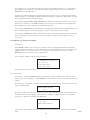
7.5
DISPLAY
The display has 3 sections which can be programmed to display a selection of variables. Each section has a
parameter which is used to select the variable which is displayed. They are located in SET-OUTPUT-DISPLAY. The
required option is selected from the list as shown below.
■
0
0
12.35
←−− UPPER DISPLAY
11:59 0
0
←−−−−−−−−− MIDDLE DISPLAY
←−−−−−−− LOWER DISPLAY
Display option parameter number
Description
D800
PV process value
D801
Sludge density
D805
% Current out
D806
Current output (mA)
D821
RL1 run time
D822
RL2 run time
D844
Control unit temperature
D850
Attenuation at 1 MHz
D851
Attenuation at 3.3 MHz
D860
Sensor frequency
P730
Date
P731
Time
Bargraph
Please note that the bargraph only works on the
lower display and it shows % current output.
7.6
BACKLIGHT
IP258
28
The display has a backlight, which can be set to On, Off or Auto. When set to Auto the backlight automatically turns
off after a few minutes if no keys are pressed.
7.7
ENGINEERING
FREQUENCY SET
The frequency of operation is normally set automatically. Under certain conditions it may be advantageous to force
the control unit to operate at either 1 MHz or 3.3 MHz. This should not be done without consulting the factory.
7.8
SYSTEM
TEST – CURRENT OUTPUT
The current output is calibrated in the factory and should not require any adjustment. However, if required, it is
possible to adjust the 4mA and 20mA points using a calibrated meter. This is done by following the procedure below.
1.
2.
3.
4.
5.
6.
7.
Connect a millammeter to the current output terminals (No. 16 and No. 18).
Ensure the toggle run padlock is open.
Access the SETUP – SYSTEM – TEST – CURRENT OUTPUT MENU.
Select either the “4mA out adjust” or the “20mA out adjust” and press ENT.
Read the actual current on the calibrated meter.
Enter this value in the chosen parameter and press ENT.
Check that the actual current is now exactly 4mA or 20mA.
For diagnostic purposes the current output can be driven to any value between 4mA and 20mA (SETUP – SYSTEM –
TEST – CURRENT OUTPUT – Set current). With a suitable meter connected to the current output terminals a value
can programmed on the control unit and the same value will appear on the meter.
This programmed current will remain until the toggle run padlock is closed.
SETTINGS
Keypad sound
The keypad sound can be turned on or off according to the users preference. It is controlled by SETUP – SYSTEM –
SETTINGS – Keypad sound.
IP258
29
8.0 HART SMART Communications
The MSM400 is compatible with the HART digital signalling system, either as well as the 4-20 mA output , or on a
Bus system. MSM400 supports Version 5.x of the HART protocol, and is fully supported by the MOBREY CK-1 HHC
(Hand Held Communicator) and by the UNIVERSAL 275 HHC. It is normally necessary to load the Universal HHC
with the transmitters Device Description to access anything more than the basic transmitter information-contact
Mobrey Measurement for details. The MSM400 can also communicate with the MOBREY H-View PC based system.
Normal requirements of the loop impedance apply to allow the HHC to communicate properly. The MSM400 has a
built in 270 ohm load, which can be selected if required-see section 4.6. This section also shows the special
terminals in the MSM400 terminal compartment available for connection of a HHC across the current output. The
MSM400 Cn number in relation to HART circuits is 1.
Please consult the HHC manual to see how to interrogate the Universal and Transmitter specific parameters.
The HART messages and Transmitter/Sensor ID Numbers are accessed and set up (where allowed) by the operator on
the INFORMATION Structure, APPLICATION+CONTROL UNIT+SENSOR screens. Some of this data is factory preset,
and is not alterable, to make the MSM400 identifiable to Universal communicators. But the main Description, Tag
Number and Message should be used to identify the equipment and the actual site application for site operator use.
The Normal Universal Commands are always available over the HART interface--PV-Process Value
% of current output (% of FSD)
Actual mA current output being transmitted
Alarms active
Temperature (inside the electronics housing)
PV for 0 or 4 mA output as programmed
PV for 20 mA output as programmed
PV units of measurement
Time Damping used on the measurement
Description (Customer supplied)
Message (Customer supplied)
Tag Number (Customer supplied)
9.
MAINTENANCE / INSPECTION
9.1
Spares
The MSM400 is a factory built in instrument and apart from the mains fuse there are no spare parts that can be
fitted in the field. Should the MSM400 require any repair or replacement parts, it must be returned to Mobrey
Measurement for action.
CONTROL UNIT
No maintenance is required beyond occasional cleaning of the enclosure with a damp cloth. Solvents or bleaches
should not be used. The fuse may only be replaced with the same type and rating. Do not modify or attempt to
repair the unit.
SENSORS
No maintenance is required beyond occasional cleaning. The frequency of cleaning will be determined by
experience. A message warning that cleaning is required may be generated when performing routine zero
calibrations. Refer to Section 6.1
IP258
30
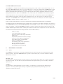
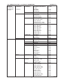
FULL MENU STRUCTURE - LOCATION OF PARAMETERS
MAIN MENU
SUB MENU 1
SUB MENU 2
PARAMETER DESCRIPTION
TOGGLE RUN
CALIBRATION
(specific)
Par No.
Toggle
AUTOCAL
MANUAL ENTRY
SENSOR
ZERO REF
SPAN
LAB VALUES
SETUP
APPENDIX A1
DUTY (Mode)
PV Calculation
DESLUDGE
INPUT
SENSOR INPUT
OUTPUT
CURRENT
OUTPUT
RELAY
SET ZERO
SET SPAN
LAB VALUES
Max % solids
Sensor Gap
Sludge Type
dB Factor @ 1MHz
dB Factor @ 3MHz
Zero Ref @ 1MHz
Zero Ref @ 3.3MHz
Date of Zero Ref
Initial Zero Ref @ 1MHz
Initial Zero Ref @ 3.3MHz
Span 1 @ 1MHz
Span 1 @ 3.3MHz
Span 2 @ 1MHz
Span 2 @ 3.3MHz
Span 3 @ 1MHz
Span 3 @ 3.3MHz
Date for Span 1
Date for Span 2
Date for Span 3
Lab Value 1
Lab Value 2
Lab Value 3
Max % Solids
PV Units
Density Units
Description
Message
Tag
Start On
Stop On
Do not Start if
Stop If
Start Time #1
Interval #1
Start Time #2
Interval #2
Serial Number 1
Type 1
Damping 1
Lower range value
Upper range value
Alarm action
0-20mA/4-20mA
Relay 1 mode
Relay 1 On Point
Relay 1 Off Point
Relay 1 Min On Time
Relay 1 Max On Time
RL 1 Min Off Time
Relay 2 mode
Relay 2 On Point
Relay 2 Off Point
Relay 2 Min On Time
Relay 2 Max On Time
RL 2 Min Off Time
L125
L126
L127
P100
P101
P102
P103
P120
P121
P122
P123
P124
P130
P131
P132
P133
P134
P135
P140
P141
P142
P150
P151
P152
P160
P200
P201
P240
P241
P242
P250
P251
P252
P253
P254
P255
P256
P257
P300
P301
P302
P400
P401
P402
P403
P410
P411
P412
P413
P414
P415
P420
P421
P422
P423
P424
P425
IP258
31
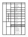
MAIN MENU
SUB MENU 1
SUB MENU 2
PARAMETER DESCRIPTION
Par No.
SETUP (Contd)
ALARM
MONITOR
Memory Fault Alarm
PV Out of Limits
Current Saturated
Temperature Out of Limits
Logging Memory Filling
Digital Input 1 Active
DISPLAY
Display Select 1 (upper)
Display Select 2
Display Select 3
Backlight On/Off
LOGGING
Interval
Fast Log Select
Overwrite Old
ENGINEERING
Frequency
(setup)
SENSOR LIMITS
Min dB
Max dB
Sensor Dirty Threshold
SYSTEM
TEST CURRENT OUTPUT 4mA output adjust 1
20mA output adjust 1
Set Current 1
SETTINGS
Date
Time
Keypad Sound On/Off
FIXED
Model Code
Serial Number
Hardware Version
Software Revision
HART
Manufacturer’s Code
Unique ID
Universal Command Rev
TS Command Rev
Preamble Bytes
Flags
READINGS
PV(process variable)
SV (Sludge Density)
% Current Output 1
Current Output 1
Totaliser
RELAY
RELAY RUN TIMES Relay 1 Run Time
Relay 2 Run Time
ALARM REPORT
DIAGNOSTICS
Digital input status
Temperature
Sensor
Attenuation @ 1MHz
Attenuation @ 3.3MHz
Attenuation unsmoothed
Signal level (Raw A/D bits)
Span Average @ 1MHz
Span Average @ 3.3MHz
Sample Average @ 1MHz
Sample Average @ 3.3MHz
Slope 1
Slope 3
Frequency of operation
Max. density measurable
P540
P541
P542
P543
P544
P545
P570
P571
P572
P575
P590
P591
P592
P630
P640
P641
P642
P700
P701
P702
P730
P731
P735
D750
D751
D752
D753
D760
D761
D762
D763
D764
D765
D800
D801
D805
D806
D810
D821
D822
D830
D835
D844
D850
D851
D852
D853
D854
D855
D856
D857
D858
D859
D860
D861
IP258
32
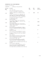
APPENDIX A2: FULL LIST OF FUNCTIONS
Parameter list and description
P=Parameter,
D=Diagnostic Display Parameter
Parameter
No.
P100
P101
P102
P103
P120
P121
P122
P123
P124
Description
Sensor Gap in mm.
This is a user entered parameter (optional).
This value is ignored when an alternative span
calibration is caried out (i.e. method two or three).
Sludge type
The user can select from a list of sludge type to set
up the span for the calibration procedure (optional).
Each sludge type is associated with an attenuation
factor for each frequency. This value is ignored when
an alternative span calibration is caried out
(i.e. method two or three).
dB Factor @ 1MHz
A user alterable parameter. This is the attenuation
number in dB/% at 1MHz. This is used for the span
calibration (method three).
dB Factor @ 3.3MHz
A user alterable parameter. This is the attenuation
number in dB/% at 3.3MHz.This is used for the span
calibration (method three).
Zero Ref @ 1MHz
This is the value in dBs (@ 1MHz) that is stored in
the control unit when a zero calibration is carried out.
This value is over written each time a zero calibration
is carried out.
Zero Ref @ 3.3MHz
This is the value in dBs (@ 3.3MHz) that is stored in
the control unit when a zero calibration is carried out.
This value is over written each time a zero calibration
is carried out.
Date of Zero Ref
This is automatically stored by the control unit when
the zero calibration is done. The actual date can be
set-up in the ENGINEER menu (P730)
Initial Zero Ref @ 1MHz dB’s
This is the value in dBs (@ 1MHz) that is stored in
the control unit when the initial zero calibration is
carried out.This value is compared with subsequent
zero calibrations.0 must be entered to reset or clear initial
zero value
Initial Zero Ref @ 3.3MHz dB’s
This is the value in dBs (@ 3.3MHz) that is stored in
the control unit when the initial zero calibration is
carried out.This value is compared with subsequent
zero calibrations.0 must be entered to reset or clear initial
Min
value
Max
value
Default
Ex-Factory
0
1000
0.0
-
-
none
0
-
0.000
0
-
0.000
-
-
16
-
-
16
-
-
--/--/----
-
-
0
IP258
33
Parameter
No.
Description
Min.
value
Max.
value
Default
Ex-Factory
P130
P131
P132
P133
P134
P135
P140
P141
P142
P150
P151
P152
P160
P200
Span 1 @ 1MHz
Measured attenuation
Span 1 @ 3.3MHz Measured attenuation
Span 2 @ 1MHz
Measured attenuation
Span 2 @ 3.3MHz Measured attenuation
Span 3 @ 1MHz
Measured attenuation
Span 3 @ 3.3MHz Measured attenuation
Date for Span 1
Date for Span 2
Date for Span 3
Lab Value 1
Lab Value 2
Lab Value 3
Max % Solids
PV Units
The PV units can be selected from a list
(%, kg/hr, lb/hr,g/l, ppm, None)
Density Units
Description
16 character user-defined description of application, say.
Message
User set up message for HART info
Tag Number - Control Unit
User-defined alpha-numeric entry up to 32 characters in
accordance with HART. May be entered by keypad.
Start On
This parameter is used to set up the mode of start
for a desludge operation and is selected from a list
(Time, PV, Ext. Trig)
Stop On
This parameter is used to set up the mode of stop
for a desludge operation and is selected from a list
(Time, PV, Ext. Trig)
Do not Start if
This parameter is used to set up the mode 'do not start if'
for a desludge operation and is selected from a list
(Light sludge, Ext trigger)
-
-
0.0
0.0
0.0
0.0
0.0
0.0
0
0
0
0
0
0
-
-
%
%
MSM400 MONIT
32 Chars
MSM40055
Stop If select from list
This parameter is used to set up the mode 'stop if'
for a desludge operation and is selected from a list
(Light sludge, Ext trigger)
P201
P240
P241
P242
P250
P251
P252
P253
P254
P255
P256
P257
P258
P300 P
P301 P
P302
Start Time #1
The time of day that the first desludge cycle starts
Interval #1
The time interval for the first desludge cycle
Start Time #2
The time of day that the second desludge cycle starts
Interval #2
The time interval for the first desludge cycle
Max retries
Sensor Serial Number
User-settable
Sensor Type
dB Damping
-
1
3
none
1
3
none
1
3
not used
1
3
not used
00:00
23:59
7:00
00:00
23:59
1:00
00:00
23:59
00:00
00:00
-
23:59
Not implemented
-
00:00
-
IP258
34
Parameter
No.
Description
P400
Lower range value
The mA set point for minimum PV in selected units
Upper range value
The mA set point for maximum PV in selected units
Alarm action
The is the value that the current will drive to on alarm
action. The alarm action is programable and is selected
from list (3.6/21mA/hold last reading).
0-20mA/4-20mA
The mA output is selectable by user,
either 0 or 4 to 20mA
Relay 1 Mode
Select Relay function from a list (Off, Set Point,Desludge
Alarm, Totaliser, Fault)
Relay 1 On Point
The value of the variable (as set in relay mode parameter)
at which relay 1 turns on. Programmable by user
Relay 1 Off Point
The value of the variable (as set in relay mode parameter)
at which relay 1 turns off.
Relay 1 Min On Time
A programmable parameter for the minimum on time
of relay 1. This is to overcome slugs of clear liquor at
the start of desludge cycles
Relay1 Max On Time
A programmable parameter for the maximum on time
of relay 1. This is to ensure, for example, a pump does
not continue to run due to a faulty signal from sensor.
Relay 2 Mode
Select Relay function from a list (Off, Set Point,Desludge
Alarm, Totaliser, Fault)
Relay 2 On Point
The value of the variable (as set in relay mode parameter)
at which relay 2 turns on. Programmable by user
Relay 2 Off Point
The value of the variable (as set in relay mode parameter)
at which relay 2 turns off. Programmable by user
Relay 2 Min On Time
A programmable parameter for the minimum on time
of relay 2. This is to overcome slugs of clear liquor at
the start of desludge cycles
Relay 2 Max On Time
A programmable parameter for the maximum on time
of relay off. This is to ensure, for example, a pump does
not continue to run due to a faulty signal from sensor.
Relay 1 Min Off Time
Relay 2 Min Off Time
P401
P402
P403
P410
P411
P412
P413
P414
P420
P421
P422
P423
P424
P415
P425
Min.
value
Max.
value
Default
Ex-Factory
-
-
0
-
-
auto
1
3
hold
1
2
4-20mA
1
5
set point
-
-
0
-
-
0
0:00
999.59
000:00
0:00
999.59
000:00
1
5
set point
-
-
0
-
-
0
0:00
999.59
000:00
0:00
-
999.59
-
000:00
-
IP258
35
Parameter
No.
Description
P540
Memory Fault Alarm
If the control unit detects a memory fault
PV Out of Limits
If the Pv is out of limits then an alarm can be reported by
a relay, current output or by both
Current Saturated
If the current is saturated is out of limits then an alarm
can be reported by a relay, current output or by both
Temperature Out of Limits
If the temperature is out of limits then an alarm can be
reported bya relay, current output or by both
Digital Input 1 Active
Display Select 1 (upper)
This parameter designates what is shown on the upper
display and can be selected from a list (PV, %, clock)
Display Select 2 (mid)
This parameter designates what is shown on the mid
display and can be selected from a list (PV, %, clock)
Display Select 3 (lower)
This parameter designates what is shown on the lower
display and can be selected from a list (PV, %, clock)
Backlight On/Off
Set Frequency of Operation
High, Low or Auto
Min dB
Max dB
Sensor Dirty Threshold
A user alterable value in dBs.The control unit
compares successive zero calibrations and if the
difference exceeds this value then the control unit
displays the warning 'CHECK SENSOR CLEAN'.
4mA output adjust
Factory calibrated. The user can adjust the 4mA output
via the up down arrows
20mA output adjust
Factory calibrated. The user can adjust the 20mA output
via the up down arrows
Set Current
Force current to a value to check loop equipment
Date
Time
P541
P542
P543
P545
P570
P571
P572
P575
P630
P640
P641
P642
P700
P701
P702
P730
P731
Min.
value
Max.
value
Default
Ex-Factory
0
3
both
0
3
both
0
3
none
0
-
3
-
none
-
1
-
- Time
1
-
- PV
1
-
-
- bar graph
-
-
-
-
0
-
0
-
-
735
-
-
3194
-
-
0
-
IP258
36
Parameter
No.
Description
Min.
value
Max.
value
Default
Ex-Factory
D750
D751
Model Code Hart parameter
Serial Number - Control Unit
Store as Final Assembly Number (FAN)
Hardware Revision
Factory-set
Software Revision
Factory-set, embedded in software
Manufacturer’s Code
Factory set not atlerable
Unique ID
Hart parameter
Universal Command Revision
Hart parameter
Transmitter Specific Command Revision
Hart parameter
Preamble Bytes
Hart parameter
Flags Hart parameter
PV
Sludge Density
% Current Output
Current output
Current is proportional to PV
Totaliser Value
Relay Status
Relay 1 Run-Time
Resettable - Hours & Minutes
Relay 2 Run-Time
Resettable - Hours & Minutes
Alarm report e.g. Sensor Fault, ….
Digital input status
Current input
Value of current input (mA)
Temperature
The temperature oC within the control unit
Attenuation @ 1MHz Attenuation
Attenuation @ 3.3MHz
Attenuation
Attenuation unsmoothed
Signal level (Raw A/D bits)
Raw RF A/D output
Span Average @ 1MHz (dB)
Diagnostic parameter that averages the span calibrations
Span Average @ 3.3MHz
Diagnostic parameter that averages the span calibrations
Slope 1
The value of the attenuation in dB/% @ 1MHZ
determined by the control unit.
Slope 3
The value of the attenuation in dB/% @ 3.3MHZ
determined by the control unit.
Frequency of operation
Diagnostic of frequency(ies) being used (MHz)
Maximum density
The maximum density that can be measured.
This value is calculated from zero and span data.
-
-
-
-
-
-
-
-
-
-
-
-
-
-
-
-
-
-
-
-
-
-
-
-
-
-
-
-
-
-
-
-
-
-
-
-
-
-
-
-
-
-
-
-
-
-
-
-
-
-
-
-
-
-
D752
D753
D760
D761
D762
D763
D764
D765
D800
D801
D805
D806
D810
D820
D821
D822
D830
D835
D841
D844
D850
D851
D852
D853
D854
D855
D858
D859
D860
D861
IP258
37
APPENDIX A3 : HART and PSION Operating Instructions
1.0.
HART CONSIDERATIONS
Special Considerations for HART
If the HART communications facility built into the control unit will be used at the time of installation or
during its future working life, then it is essential that a resistive load of at least 250 Ohms is connected in the
supply cable. This may be provided by other devices in the loop (Chart recorder, meter, etc.) or more usually
by installing a standard 270 Ohm 0.25W resistor in series with control unit. In this way the master device will
be able to signal to the control unit without the power supply short-circuiting the data.
In addition, excessive cable capacitance will attenuate the HART signalling and so the capacitance must
anyway be limited if HART communications is to be used. The RC time constant for the network must not
exceed 65µs, e.g. if the network resistance is, say, 650Ω then the maximum network capacitance is 0.1µF.
HART transmitters are often given a Cn number where n is the multiple of 5000pF which the device presents
to the network. In the case of MSM400 the value of n is 1 since its capacitance is below 5000pF.
Total loop resistance and capacitance
Additional equipment such as indicators or recorders may be inserted in the loop subject to the resistance and
capacitance limits discussed above.
Cable trays
It is recommended that HART signal cables are not run alongside power cables.
1.1
Multi-drop installations (MSM400 in HART digital mode)
Up to 15 transmitters may be connected in parallel with each other, and each must be set to a different
HART address between 1 and 15. When HART transmitters are connected in multi-drop mode, each control
unit draws a fixed current of 4mA.
Compatibility with other HART instruments.
Any HART instrument, regardless of the manufacturer, may be connected in parallel with another to create a
multi-drop network. They may be combined with separately powered, current sourcing or sinking devices but
care must be taken to ensure that the HART signal current passes through the 250W minimum impedance to
establish communications. For full details of HART instrument availability, refer to the HART Communication
Foundation publications or individual manufacturers' literature.
Handheld Communicators
A handheld communicator (HHC) may be connected across the network (downstream of the minimum 250
Ohm loop resistance) to programme or interrogate a HART control unit. Some HHC’s support only a subset of
a transmitter’s functions, and will thus only access the control units Universal and Common Practice
commands. However, the MSM400 is fully supported by the MOBREY-CK1 HHC and by the UNIVERSAL 275
HHC (provided the 275 is loaded with the transmitter’s Device
Description – contact Mobrey Measurement or the HART Communications Foundation for details).
IP258
38
2.0
SMART COMMUNICATION WITH THE MOBREY MSM400
With a SMART HHC, you can make adjustments and calibrate your MSM400 at any point on the two wire
connection to the control unit. You can also make many other adjustments and obtain operational and
diagnostic information using the HHC.
Alternatively, Mobrey have a PC based software package called Mobrey H-View which allows you to make
adjustments and obtain readings through a standard PC. Contact Mobrey or your local agent for details.
If you have a Mobrey type CK HHC (Psion Organiser based) and the appropriate datapak, refer now to
Appendix D for details of assembly, connection and menu structure before reading on to the specific
adjustments listed below.
If you have another type of SMART communicator or computer based software tool, you must ensure that the
MSM400 Device Description (DD) is correctly loaded or compiled to gain access to all of the MLT parameters.
If you do not have the MSM400 DD loaded, you will only be able to access the Universal and Common
Practice commands.
Contact or any other HART Host Subscriber to update your communication device with the latest MSM400
DD.
The MSM400 control unit is a SMART instrument using the HART protocol to communicate with external
devices.
The Mobrey HHC is a hand-held organiser based communication device fitted with a HART interface to allow
communication with Mobrey HART instruments.
By connecting the HHC across the two wire loop at any point downstream of the minimum 250 Ohm loop
resistance, communication can be established. The MSM400 has integral test pins provided for this purpose.
Refer to Appendix D3.0 for details of HHC connection and operation.
The following paragraph details how to re-range and change damping using the HHC once communication
with the MSM400 has been established.
2.1
Calibration adjustments at operating conditions.
Important note : Making changes to the position or span of the 4-20mA range with a communicator can cause
the control unit to make step changes in the output. You should arrange to set your plant control loop to
“Manual” before making changes if this could be a problem.
4mA point – from the “Program” menu / “Calibrate” sub-menu, access Parameter P500. The factory default
value is “0”.
Enter the desired new value of the PV (Process Value), normally the sludge level in % solids, required to give a
4mA output, and confirm when prompted by pressing the “exe” key that this is correct. The new value is now
entered and saved.
Note, the 4mA point can be positioned above the 20mA point to reverse the operation of the control unit,
thus giving a falling current output with rising sludge level.
20mA point – from the “Program” menu / “Calibrate” sub-menu, access Parameter P501. The factory default
value is “A”. This represents “Automatic” and in this case means that the 20mA point is automatically set to
the maximum range of the control unit.
Enter the desired new value of the PV (Process Value), required to give a 20mA output, and confirm when
prompted by pressing the “exe” key that this is correct. The new value is now entered and saved.
Damping – from the “Program” menu / “Engineer” sub-menu, access parameter P625. The factory default
value is 5s.
Enter the desired new value in seconds and press “exe” to confirm and save the new value.
IP258
39
2.2
Further customisation using the SMART HHC
There are some other features of the control unit that can be changed at this stage:
Identity
The following parameters can be recalled from the “Info” menu, and those shown * below can be site
configured :P701
P710
P700
P702
P722
P760
P660
MESSAGE
TAG
DESCRIPTION
DATE
FINAL ASSY No.
SENSOR SERIAL No
PASSWORD
*general purpose 32 character message
*control unit identifier (8 characters)
*E.G. control unit application or location (16 char)
Automatically updated on exit if changes made
Factory set – hardware assembly number
Factory set – LVDT serial number
* 3 level password system.
Simply enter any message or tag number as appropriate and the control unit will retain this information in
memory for future identification. This is particularly useful if you are likely to interrogate the control unit
using the HHC from a remote location.
Refer to Appendix D for more detailed information.
Units of Operation and Display
The units displayed on the display or the HHC when used can be changed from the default “%” using P610
accessible through the “Program”Engineer sub-menu.
IP258
40
Appendix D
D.
HANDHELD COMMUNICATOR – MOBREY – CK*
D.1.0. Hand Held Communicator – Assembly Instructions
The MOBREY-CK* SMART Hand Held Communicator is supplied as a kit of items (Figure DI) which are
assembled as follows:
D.1.1 Remove the lower sliding cover (1) of the Psion organiser (2) completely to expose the battery compartment lid
(3) at the base of the keypad, and the two slots for Datapaks behind the right hand side of the keypad.
D.1.2 Remove the lower of the two blank Datapak mouldings and insert the preprogrammed Mobrey SMART Datapak
(4), pressing the unit home. This lower slot is the “C” slot in Psion Organiser memory.
D.1.3 Remove the battery compartment lid (3) and insert the 9V battery (5), positive terminal first. Replace the
battery compartment lid (3) and the lower sliding cover (1) over the base of the Psion Organiser. Leave the
keyboard exposed.
D.1.4 At the top of the Psion Organiser above the LCD, slide the cover across to the right to expose the connector.
Insert the MOBREY SMART interface unit (6) in this slot.
D.1.5 The lead used to connect the MSM400 cabling is plugged into the MOBREY SMART interface unit. On the
MOBREY-CK1 and MOBREY-CK3 this is via a 3.5mm jack plug. On the -CK2 a multi pin plug is used. The
latter also has the hook-on connectors built into the leads instead of push on crocodile clips.
D.1.6 The MOBREY SMART Interface Unit has another socket at the top left hand side for connection of a standard
Psion external power unit as an alternative to battery operation.
D.2.0.
Notes
D.2.1 Although it is possible to insert two Datapaks into the HHC, this is not recommended as a conflict between
them can occur.
D.2.2 The MOBREY-CK* Datapaks enable communication with both MSP100 ultrasonic level transmitters and
MSM400 displacement level transmitters, and also gives generic support for all other HART transmitters.
D.2.3 When not in use, remove the Mobrey SMART Interface unit from the HHC to prolong battery life.
D.3.0.
Requirements for loop powered SMART Operation (Refer to Fig. DII)
D.3.1 The MSM400 control unit requires a DC supply voltage of 2.5 volts at its terminals for satisfactory operation
(V3).
D.3.2 Resistance between any two SMART Interface connection points must exceed 250 ohms. (R1).
D.3.3 For the minimum DC supply voltage (V1) to be calculated, the voltage drops in the loop at 20mA must be
assessed. The absolute minimum value of V1 will therefore be 7.5 volts, since 5 volts is required for the
voltage drop across R1 at 20mA. (See Note 2 below).
D.3.4 If R1 is 250 ohms or more the SMART communicator can be connected between B1-B2, or C1-C2, or D1-D2
or E1-E2. It is also allowable to connect across the SMART Load resistor R1, on B1-A1, or across any
resistance in the circuit that exceeds 250 ohms.
D.3.5 The current loop load resistance R2 can be considered to be part of the 250 ohms needed as the SMART
Load resistor. In this case R1 + R2 must exceed 250 ohms, and the communicator can be connected
between C1-C2, D1-D2, E1-E2, or C1-A1.
IP258
41
Fig DII. : Loop diagram
IP258
42
Fig D1 : MOBREY-CK* HHC assembly
IP258
43
Technical Notes:
1.
At no time can the SMART communicator be attached across A1-A2, since the DC supply effectively short
circuits the transmitted and returned digital communications signals.
2.
The minimum DC Voltage V1 required for satisfactory 20mA loop operation can be calculated from the
formula –
V1 > 2.5 + V2 + [20 x 10-3 ]x (R1 + R2 + R4 +R5)
D.3.6.3.
An alternative way of looking at this voltage requirement is in terms of the maximum loop resistance
that can be tolerated, which has to be less than (V1 – 2.5) x 50 ohms.
The maximum allowable value for V1 is 30 Volts.
D.3.6.4.
The HART protocol itself sets the maximum values that can apply to the loop resistances, labelled R1
to R5.
The total load on the loop (R1 + R2 + R4) must not exceed 1100 ohms.
In addition the maximum length of cable in a loop working on the HART protocol is specified as 3000
metres on a single screened loop cable, or 1500 metres if multicore multi-loop cabling is used.
D.4.0. How to connect the SMART Communicator
Assemble the Psion based SMART Communicator unit as shown in Fig. DI fitting the battery, 100 SMART
Datapak, SMART Interface unit and lead. The push on crocodile clips are optional.
Power the MSM400 Control unit from a DC supply as shown in Figure DII. A 250 ohm (or higher value) load
resistance must be incorporated in the loop.
The SMART Communicator is self powered and draws no current from the loop.
The two wires from the SMART Communicator are interchangeable – it does not matter which way round they
are connected.
a)
These two wires can be connected to the HART test pins inside the lid of the MSM400 control unit, using
the crocodile clips provided on the CK1 or CK3.
b)
Alternatively connection can be made via the crocodile clips or hook on probes to each wire of the 2
wire current loop at a convenient terminal box or strip.
c)
At the control room the two wires can be connected either across the “SMART” Load resistor or between
a terminal on the chart recorder/indicator and the other side of the loop.
IP258
44
D.5.0. Hand Held Communicator : Operation
Language
Initially the Psion Organiser will power up and display the Psion Copyright message, when the ON button is
pressed. Then a choice of languages will be offered. This applies to the operation of the Psion Organiser
functions only, MSM400 programme, although Datapaks will be available from MOBREY in different
languages.
MSM400 Programme
The main menu selection of the Psion Organiser is automatically amended to include the MOBREY option
when the Datapak is fitted. This cannot be permanently repositioned nor deleted.
Time
The only data in the Psion Organiser used by the MOBREY programme is the date held in the Organiser
memory. On making changes to an MSM400 the date will be stored in the MSM400 control unit
microprocessor, as shown by the Psion Organiser. To set this clock, select TIME, press MODE, select SET, and
use the arrows to select the correct date and time on the display. Then press EXE to start the clock, and ON/
CLEAR to return to the main menu.
Disconnecting SMART Interface
To disconnect the interface unit it is necessary to press down the catch in the top centre face of the unit to
release the lock, when the interface can be pulled vertically away. The Psion programme knows when the
interface is not present and will no longer seek to find an instrument connected – it will only allow OFFLINE
programming. Naturally, no diagnostic parameters are made available.
Note : Programme Lock-up
This will occur if the interface unit is disconnected from the Psion before it has finished all communications,
or as a function of the Psion ON button features. The LCD is frozen:
a)
Reconnect the interface unit, to allow completion of the procedure.
b)
If the Lock-up has occurred after pressing the ON/CLEAR button, it probably results from the Psion
Organiser “CLEAR” function which stops/freezes all programmes running at the time. The programme can be
restarted by pressing any button again (except Q).
c)
If the Lock-up occurs as a result of an incomplete procedure, there is no easy release process. The LCD on
the SMART Communicator is frozen. Once the buffer store for instructions has been filled with 16 command
key instructions, a bell like sound is made when any further button is pressed. The best escape route is to
remove the battery to totally clear the memory of the Psion. Beware that this will also clear the date, diary
and alarm memories of the Psion Organiser itself. Clearing the memory occurs after approx. 30 seconds with
no battery, or immediately on pressing ON/CLEAR after the battery has been removed.
IP258
45
D.6.0 How to drive a Psion based SMART Communicator
Familiarity with the Psion
The Psion is supplied with several manuals to described its function. The main keyboard functions that are
important are the yellow keys. Press “ON” and see the functions of the arrows to move the cursor around the
selections in the menu. Press “EXE” to see the Psion functions. Note that a short cut to selecting a menu
item is to press the key with the initial letter of the required selection – for example “O” switches the unit
“OFF”.
Note that if the “CALC” option is selected, the keyboard changes from the “Alphabet” marked on the keys, to
the “numbers” and symbols marked above the keys. The Psion selects the expected function required of the
keyboard. This function can be changed back by depressing the “SHIFT” key.
MOBREY Menu
If “MOBREY” is selected from the start up menu on the Psion, by pressing “EXE” the space available in the A
memory of the Psion is checked. If there is insufficient then a message is displayed and the program returns
to the main menu. Data, Note Pad or Diary files in A must be removed to allow the program to run. The
SMART Communicator then establishes whether the SMART interface unit is plugged in or not.
10:41
MOBREY Find Save
Diary Calc Time
Notes World Alarm
When the SMART interface is not connected, the Communicator does not look for an instrument – it offers
OFF-LINE programming.
When the SMART interface is connected to the Psion, on selecting the “MOBREY” menu item the programme
seeks an instrument that is expected to be functioning on a 4-20mA loop (the loop that is expected to be
connected to the SMART interface cables).
MOBREY V3.1
SEEKING INSTRUMENT
PLEASE WAIT
If the loop is not powered, or the interface cables are not properly connected to the loop, or the loop
impedance/resistance values are incorrect, the unit will fail to find the control unit.
NO SINGLE LOOP
INSTRUMENT CONNECTED
RETRY (Y)es or (N)o
Note that if the MSM400 control unit is programmed to respond as a numbered sensor on a multidrop loop, it
will also fail to communicate to the SMART communicator at this point.
IP258
46
When an MSM400 Control unit is located on the loop, this is identified and further instructions awaited.
MSM400
FOUND
TAG
TANK 1
ACCESS (Y)es or (N)o
Alternatively an Unknown Instrument may have been found, i.e. a HART instrument that is not a MSM400 or
MSP100 or MLT100. This will cause a similar message and prompt to be displayed.
UNKNOWN INSTRUMENT
TAG FLOW1
ACCESS (Y)es or (N)o
In either case pressing “Y” will cause the following prompt to be displayed:
UPLOAD ALL
PARAMETERS
NOW?
(Y)es or (N)o
Pressing “Y” will result in all the parameters being read into the HHC. If “N” is pressed then the delay
imposed by a full upload can be avoided. If parameters in the D240 to D265 and P100 to P104 are accessed
later on all the parameters in that group will be uploaded. Thus only the parameters of interest need to be
uploaded, with the minimum delay. A full upload must be done at some stage if the parameters in the
instrument are saved, printed, or used to program another instrument.
The asterisks show each transfer of digital information. If one transfer is incorrect, or corrupted, the
Communicator will advise and ask for an action decision – an example of one of these error messages
is –
NO RESPONSE FROM
CONTROL UNIT
RETRY (Y)es or (N)o
A retry will attempt to obtain the same data again, whereas the “No” decision will jump that data transfer and
collect the next set of data, to try to gain whatever information is available. The data loaded in the Working
register for the missing parameters will be the default values, instead of those present in the instrument.
Typically, a full upload data collection time is between 30 and 45 seconds.
The main screen describing the equipment now gives control unit identify information – i.e.
MSM400
TAG TANK ALL
MSM400 XDUCER
ACCEPT (Y)es or (N)o
Line 2 of the display is the Tag number loaded as Parameter 01, and Line 3 is the Description loaded into
P700. If this is not acceptable the program suggests a return to the Psion menu functions. If it is
acceptable, pressing the Y button will give access to the FUNCTION menu of the MSM400 Program. The
MSM400 control unit parameters are now loaded into the SMART Communicator (Psion Organiser) memory in
the WORKING Register.
IP258
47
Future work on this data can be carried out whilst the SMART communicator is connected to the loop, in
which case all changes will be immediately sent to the MSM400, or after disconnection of the Communicator,
in which case the amended programme will have to be stored in the “OFFLINE” register of the communicator.
The Psion Organiser has four separate registers of data relating to the MSM400 control unit. These registers
are named WORKING, SAFE, OFF-LINE and DEFAULT, and are explained in Section D13.0. All changes and
operations occur in the Working Register, identified by W on the right hand end of line 2 on the display. The
other registers are for storage and transfer of data between transmitters or for reference.
D7.0 Introduction and FUNCTION menu
The microprocessor in the MSM400 control unit retains the calibration required for the particular application
or tank involved, once this has been entered into the memory (EEPROM). On the initial interrogation of the
control unit, this information is transferred to the SMART Communicator using the HART protocol, which
defines the command structure and message format.
When received by the SMART Communicator, these messages are loaded into the WORKING register (which
resides in the Psion Organiser memory), which then adds the descriptions and other information shown on the
4 line liquid crystal display. The operator is presented with the information he requested, in a meaningful
format in relation to the application.
The first selections of the MSM400 control unit programme use a menu structure, where the operator
identifies the part of the programme required from a list of options available. The detailed information under
each menu item can be inspected, after selection, by scrolling through the listing. Each item is given an
identifier in the top right hand corner of the screen, identified by a parameter reference number, to allow
accurate recording of the data interrogated and to simplify communications relating to this data.
The programme is divided into two main sets of data, selected from the FUNCTION menu. The FUNCTION
menu is the first programme screen presented when the data from the control unit is accepted and
interrogation is to begin.
***** FUNCTION *****
Calibration
Monitor Program
Info
Toggle access
Help
D**
MONITOR – The data presented on selecting MONITOR is the live “read only” information from the control
unit, for example the liquid level in the tank, and the value of the current output. These parameters are
labelled D, for Display information parameters, and are indexed between D200 and D265. The Display
parameters are described and listed in Section D10.0
PROGRAM – The data presented on selecting PROGRAM is the operator adjustable data used to configure the
control unit for the particular application. These are “read/write” parameters, labelled P for Program
parameter, and are indexed from P300 to L104. The Program parameters are described and listed in Section
D10.0
FIXED DATA – These are the MOBREY factory preset display parameters, identifying the equipment type, serial
number, software information, etc.
BACK UP – This menu item controls the transfer of data between registers or a file available in the Psion
Organiser memory: operation is described in Section D13.0.
D** - Allows direct access to a Display parameter by entering the relevant code number.
HELP – The HELP information display screens give some introductory advice on the use of the keys on the
Psion Organiser and the Programme structure.
IP258
48
D7.1 Monitor/Display Parameters – D**
Access and programme structure
The Display Parameters (D***) are separated into several blocks according to the type of operator read only
information. See menu structure in the main body of the manual.
All the Display parameters can be accessed directly from the FUNCTION menu by selecting the appropriate
identification number, e.g. D240.
ENTER PARAMETER No
D The live data recalled on the displays are updated continuously by the SMART Communicator every 0.5
seconds, and so represents the latest available information from the MSM400 control unit. When monitoring
these parameters the Psion Organiser is active and so will not switch itself off (the normal action after 5
minutes without any keyboard input).
Additional messages and codes are displayed in a priority order on the LCD when the Display parameters are
in use, to indicate exceptional tank conditions or operational problems.
D7.2 PROGRAM Parameters – P***
Access and Programme Structure
The PROGRAM Parameters are separated into three blocks. These blocks are available for operator access to
configure the MSM400 control unit as required for the particular application, or adjust the normal mode of
operation of the unit. Access to all the PROGRAM parameters is made via the PROGRAM menu.
The three blocks of PROGRAM parameters are as follows:
MODE – The normal operator adjustments equivalent to desludge setup and current input configuration.
Parameters P300 - L102.
ENGINEER – The more technical operator parameters, establishing response time, alarm delay time and HMI
(keypad sound). Parameters P400 - P562.
OUTPUT – These allow Relay and current output configure.
These PROGRAM parameters are read/write parameters, so that when a particular parameter is recalled its
value can be changed by one of three methods – either entering a new value on the blue numeral key pad, or
on the alphabet keys for a text entry parameter, or by scrolling sideways. Each of the parameters uses only one
of these methods : sideways scrolling is prompted by the appearance of horizontal arrows on line 3 of the
LCD. When the new value is on the display correctly, this is entered using the “EXE” key. The SMART
Communicator immediately then transmits the change to the MSM400 control unit. If the value is incorrect
or the operator wants to revert to the original value, the CLEAR/ON key will reinstate the existing parameter
value on the display, without affecting the MSM400 control unit.
Within the memory of the Psion Organiser there are four separate registers for each of the PROGRAM
Parameters. These registers are known as WORKING, SAFE, OFFLINE and DEFAULT, and are further
described in Section D13.0. All programme changes are made in the WORKING register, and these are the
values sent to the MSM400 Control unit memory. The display can be cycled through the registers by using
the MODE key, and the initial letter of the register currently displayed is shown at the right hand end of the
second line – the same line as the parameter value. Individual parameters can be moved into the WORKING
register from other registers, by pressing the EXE key whilst the required register value is displayed.
IP258
49
WORKING REGISTER
Holds the same value as is currently in the control unit.
SAFE REGISTER
Use as a backup, can only be sent to the same control unit as it was loaded from.
OFF-LINE REGISTER
General purpose register, use to program a control unit offline or transfer data between transmitters of the
same type.
DEFAULT REGISTER
The normal ex-factory values.
When a new value is programmed into certain parameters a warning message OUTPUT MAY BE CHANGED is
displayed with the option to proceed with or abort this change. This may be of importance where the output,
either digital or analogue, is controlling some process, such that a sudden change could cause problems.
D8.0 Keyboard Functions
ON/CLEAR KEY
Aborts data entry if this has been started, else returns to the previous menu.
EXE KEY
When display is read/write parameter, writes the value on line 2 or the list selection on line 3 to the control
unit.
↑ AND ↓ ARROW KEYS
Used to step through a parameter block in numerical order.
MODE KEY
Used to access the WORKING, SAFE and OFF-LINE registers and the DEFAULT value while a read/write
parameter is being displayed. The selected register is indicated by W, S, O or D on the right hand side of
line 2.
← AND → ARROW KEYS
Used to select an item from a list when <> is displayed on the right of line 3.
P*** AND D*** ENTRY
Allows direct access to a parameter via its number. Other parameters in the same group can then be accessed
by the ↑ and ↓ arrow keys.
IP258
50
HAND HELD COMMUNICATOR REGISTERS
D9.0 SAFE, WORKING, OFFLINE, DEFAULT, Registers
Introduction to Registers
From the FUNCTION screen, whilst interrogating an MSM400 control unit, there is a selection titled
“BACKUP”. This allows the data now stored in the WORKING register (i.e. the MSM400 control unit
data) to be transferred to a separate secure memory, to either retain it while making changes to the
MSM400 control unit (i.e. as a “revert to the original program” insurance data store) or to save it in
memory so that it can be copied or consulted back in the office. The registers available are
WORKING REGISTER
This is literally the work sheet where all work is done – all changes made to the parameters on the
SMART Communicator keyboard are made to the data in the WORKING Register. While the
Communicator is attached across the 4-20mA loop, the WORKING register is exactly the same as the
MSM400 control unit memory, so all changes made to the WORKING register are also made to the
control unit itself. The MSM400 control unit memory and the WORKING register in the SMART
Communicator are identical. If communication between the two units fails, then changes attempted
in the WORKING register will be rejected.
Note : The SMART Communicator can be unaware of changes to the MSM400 control unit memory
made by (a) a Primary Master (such as Mobrey H-View) also attached to this control unit loop, and (b)
the local zero and span on the MSM400.
The data existing in the WORKING register is overwritten (and therefore lost) when new data is
loaded from another register, or when the SMART communicator is reconnected to an MSM400 loop,
because the start up routine will load this new MSM400 memory into the WORKING register. To
save any data that has been entered in an “Off-loop” state (i.e. back in the office) the data must be
held in the OFFLINE register (see below).
It is recommended that the data in the WORKING register is transferred OFFLINE before disconnection
of the SMART communicator from the loop, if it is likely to be needed for reference back in the office.
However, the data in the WORKING register is retained in the Psion memory after this disconnection,
and can still be interrogated until overwritten by new data.
SAFE REGISTER
The SAFE Register is literally a register where the current MSM400 calibration data can be stored and
kept SAFE, while changes are made on the WORKING register and the SMART Communicator is
attached to the loop. If these WORKING register changes then prove ineffective or not required, the
SAFE register data can be recalled into the WORKING register (and therefore to the MSM400 control
unit) to reset all the MSM400 parameters to their original values – i.e. the values in the control unit
when the last “Backup” operation transferring the data to the SAFE register was carried out. The data
in the SAFE register can only be loaded into the WORKING REGISTER when the communicator is
attached to the same MSM400 control unit that was the source of the data – i.e. the control unit with
the same unique identifier (D08). It is not possible to transfer programmes between instruments
using the SAFE register.
The SAFE register is retained even when the Communicator is disconnected from the loop, powered
down, and then reconnected to another loop, collecting new data in the WORKING register. It is not
accessible until the correct control unit loop is interrogated, so that the check on the D08 Unique
Identifier has been satisfied.
OFF-LINE REGISTER
This is the register used for transfer of programmes between one unit and the next, or from a
programme developed on the SMART Communicator at the office desk, stored OFF-LINE and then
down loaded into an MSM400 control unit on the plant later. Such data transfer is achieved by
connecting the SMART Communicator across the relevant MSM400 loop, loading the WORKING
register with the current MSM400 program (see below) then transferring the OFF-LINE stored data
into the WORKING register – this overwrites the previous programme in the MSM400 (both the
control unit memory and the WORKING Register).
IP258
51
An obvious precaution in the above procedure after loading the WORKING register with the current
MSM400 control unit data, is to transfer this data to the SAFE register in case the OFF-LINE sorted
new programme does not give the expected result – if necessary the MSM400 can be restored to its
original programme status by transferring the SAFE register data to the WORKING register.
The OFF-LINE register is retained when the communicator is disconnected from the loop or powered
down. It is only wiped when a new set of data is transferred to the OFF-LINE register from the
WORKING register.
Only one set of parameters can be stored in the OFF-LINE register at once.
DEFAULT REGISTER
This is the register of all the normal ex factory settings for the MSM400 Control unit. It is a useful
start or reference point for programming any control unit, since the values set in each parameter are
known and only those that need The screens showing the Transfer functions of data between registers
provide step by step instruction for achieving such data transfer . There are also facilities for allowing
the normal interface between the Psion Organiser and a printer or personal computer to provide
output of the MSM400 programme data.
The options presented on the LCD are amended when the SMART Communicator senses that a loop
is not present or the Interface unit is not plugged into the Psion. In such cases OFF-LINE operation is
offered or selected automatically. After changes to the PROGRAM screens which modify data in the
WORKING Register, these changes must be saved in the OFF-LINE Register or to a Data File using the
TRANSFER function.
b)
Loop transfers
The BACK-UP selection on the main FUNCTION menu allows manipulation of the data held in the
various registers. Since all transfers are to or from the WORKING Register, the initial screen
SELECT DATA SOURCE
Safe
Off Line
Working Defaults
File
Immediately transfers data to the WORKING Register if SAFE or OFFLINE are selected. If the
source is a Data File then a location and a File name are prompted for and the data is transferred to
the OFFLINE Register followed by a transfer from OFFLINE to WORKING. This final transfer can be
prevented by pressing “N” when asked to accept that the output may be changed. If the data source
is the WORKING Register, the screen prompts for a full upload if any parameters have not yet been
read then asks for a destination decision.
SELECT DATA
DESTINATION
Safe
Off-line
File
To know where to place the data. Transfer to a Data File will prompt for a location and a file name.
The location is either the internal memory at A or a Data or Rampak in the upper side slot which is B.
The filename can be up to 8 characters long. In this case the WORKING Register remains unchanged
after the data transfer.
Please note that Parameters in the range P44 to P69 are not transferred to the WORKING Register in
any BACK-UP data transfer. These parameters are left as set up by the Service Engineer for that
particular control unit.
IP258
52
D.9.1 Printout or PC transfer of MSM400 programme data
When used “Off-Line” the Hand Held Communicator can be instructed to transfer the programme memory
into a PC or print a list of the parameters and the values in the working register on a paper printer. This is
achieved using the Standard Psion COMMS LINK routines and interfaces.
To send or receive data from a PC the COMMS LINK must be plugged in and connected to the PC port and
the CL program must be running on the PC. See the COMMS LINK manual for further details.
The Psion will set itself up for transfer to or from a PC when this option is selected.
The file name is any valid MS DOS file name including path names and extensions. The PSION/HART
program restricts the length of the input to 17 characters.
The actual transfer to a PC is a complete list of parameter numbers (P100 and P761), of the memory
values in the WORKING register. Certain parameters have numeric codes to identify the option
(normally chosen in text, such as LINEAR or HOLD). Do not modify this data while it is in the PC file.
To printout the parameter list the COMMS LINK must first be set up to match the requirements of the
attached printer with regards to the Baud Rate, start bits, stop bits and protocol. To test the printer
and get the desired settings, use the AUTO function in the SETUP menu, and experiment with the
HAND settings, try XON + DTR first.
The printout includes the parameter number, title and value of all the valid parameters in the range
P100 and P761. Where necessary the value will be related text instead of the value in the data file,
e.g. “HOLD” instead of 2.
D.9.2 Display of Parameter Data
The four different registers relate only to the \Programmed Parameters in the MSM400 memory.
When interrogating an MSM400 control unit, a typical parameter display would show:
STANDING VALUE
**** **
VALUE OF PV
AT ZERO LEVEL
P***
W
The W shown on the second line right hand end indicates that this displayed value is the value present
in the WORKING register. This can be compared with the SAFE, OFFLINE or DEFAULT equivalent values
by pressing the “MODE” button, which cycles through these registers. The data displayed is labelled
with the initial letter of the register selected. This is useful for comparing transmitters (between W and
O) or noting changes on this control unit (Between W and S). A transfer of this single parameter can be
made into the WORKING register by pressing “EXE” when the desired alternative register value is
shown on the LCD – the display will show the letter changing to W to acknowledge the transfer.
D.10.0ERROR MESSAGES ON THE HHC
D.10.1Alarm and Error Messages
Throughout the programming of the MSM400 Control unit using the SMART Communicator, any failure
of a communication message or other problem in the SMART interface will be advised with a message
on the Liquid Crystal Display. Certain error messages prompt for an operator input or decision, for
example, whether the procedure should be repeated. These need simple “Yes” or “No” responses.
Other errors, for example, “No response from control unit” when programme parameters are being
changed, will produce a reset of the parameter value back to the original value in the WORKING Register.
In the first interrogation of the control unit, each asterisk shown on the LCD represents a message,
which can contain up to 10 parameters. In the event of a failure of this communication, the option of a
retry or move to the next set of parameters is offered. It is always preferred to use “Retry” to collect a
full set of data.
IP258
53
Control unit Status Messages
Further operational alarm/error messages are shown on the LCD when any display parameter is
selected. When either Readings or Diagnostic parameters (D200 - D265) are shown, the SMART
Communicator is interrogating the MSM400 control unit every 0.5 seconds, and the information returned
includes various message signals concerning the current status of the returned echo. These messages are
displayed on the LCD line 2 for two seconds when the condition is first detected, instead of the Display
parameter value. After this display period the condition message is abbreviated to a two letter code
shown on the right hand side of the LCD, as long as the condition persists These status messages are
updated every 10 seconds. Only one status message is displayed at a time, in a priority order, as listed
below, to see all the alarms present use P520 - P525.
CURRENT SATURATED (CS)
The echo currently monitored is from a process value outside the pre-programmed 4-20mA range, so
the current is either at 4mA or 20mA and is possibly not valid.
TEMPERATURE LIMIT (TL)
This indicates that the process temperature or a combination of the process and ambient temperatures
have resulted in the electronics becoming too hot or too cold. Using the HHC, check P523 to see the
maximum and minimum temperatures recorded. If the MSM400 electronics has recorded a temperature
above 55°C then the electronics may have been permanently damaged. The MSM400 should be
returned to Mobrey Measurement or your local agent for repair or replacement.
There are also various microprocessor fault messages which should be shown on the LCD, indicating
significant problems with the sensor microprocessor. For all these error conditions reference should be
made to the factory, and it will probably be necessary to return the unit for repair. The messages and
codes are:
ROM CHECKSUM
EEPROM SIGNATURE
EEPROM CHECKSUM
RAM TEST
RC
ES
EC
RT
When an Unknown instrument is being interrogated, a universal set of error messages is used:
DEVICE MALFUNCTION
PV OUT OF LIMITS
NON PV OUT OF LIMITS
CURRENT SATURATED
DV
PL
NL
CS
D.10.2Invalid Data Entry
When the Operator tries to enter a command or parameter value which is invalid, the message on the
screen will indicate this. Typical messages occur as follows:
“INVALID INPUT”
(Rejected by the Psion Organiser)
“INVALID DATA”
(Rejected by the MSM400 control unit)
- Parameter value entered is outside the limits allowed for that parameter, or resetting of this
parameter is not allowed as per the data entered.
“IN WRITE PROTECT MODE”
- The Password is “Closed” or does not allow access to this parameter.
“INVALID PARAMETER NUMBER”
- Parameter number entered is not known by MSM400.
IP258
54
“PASSWORD NOT OPEN”
- If the Password in the MSM400 control unit memory is set “CLOSED”, then it will not be
possible to load data from the SAFE or OFFLINE register. The Password protects the data in the
MSM400.
“INVALID ACTION NOT THE SAME INSTRUMENT”
- If an attempt is made to transfer SAFE register data to the WORKING register of an MSM400
control unit which is not the origin of the SAFE register data, this will not be allowed. The
message indicates that D731 on the currently connected loop is not the same as the D731 in the
SAFE register.
“INSTRUMENT IN MULTIDROP MODE”
- The current output control circuitry in the MSM400 control unit is only active when the MSM400
is operating as a 0-20 or 4-20mA device. In a multidrop configuration the current is set to 4mA,
and trimming and current set commands are inoperative.
D.10.3Communication Errors
Communications between the MSM400 control unit and the SMART interface/Psion organiser are subject
to error checking and acknowledgement signals according to the HART protocol. This means that only
valid messages are accepted, and if the message is invalid then it will be rejected.
The screen of the LCD will indicate if a message has not been received correctly. This is perhaps most
likely to be seen when the Display parameters are being used, since these are updated with a new value
in a message every 0.5 seconds. If the message is received incorrectly, the second and third lines of the
display will show one of the following messages:
VERTICAL PARITY ERROR IN REPLY
OVERRUN ERROR IN REPLY
FRAMING ERROR IN REPLY
LONGITUDINAL PARITY ERROR IN REPLY
BUFFER OVERFLOW IN REPLY
Which describe the cause of the fault.
There is an identical group of errors in the outgoing message:
VERT PARITY ERROR IN OUTGOING MESSAGE
OVERRUN ERROR IN OUTGOING MESSAGE
FRAMING ERROR IN OUTGOING MESSAGE
LONGDNL PARITY ERROR IN OUTGOING MESSAGE
BUFFER OVERFLOW IN OUTGOING MESSAGE
If this occurs frequently, it is appropriate to check the electrical connections to the instrument loop, the
presence of the SMART load resistor and that the SMART Communicator is attached at the correct
position in the loop.
The “IN OUTGOING MESSAGE” group of error messages if displayed while accessing the Programme
Parameters implies that the message from the SMART Communicator was not received correctly by the
MSM400. Therefore the instructions in the message would have been rejected, and the Parameters
remain unchanged at their previous value. This previous value will be shown on the LCD screen on the
SMART Communicator after the error message, to prompt the operator to repeat the last parameter
value amendment. During a Register transfer this message will automatically cause the Communicator
to hold transmission, and suggest a retry because of the error.
The “IN REPLY” group of error messages if displayed when programming the instrument, signals a more
significant communications failure. This indicates that the acknowledgement of the change instruction
sent to the MSM400 was incorrect. It is not known whether the Parameter value in the MSM400 was
changed or not. The SMART Communicator assumes that it was not changed, and reverts to the original
IP258
55
OFF-LINE MEMORY TRANSFERS
D0 - D8 :
MSM400
IP258
56
(pre change) value : this prompts the operator to re-enter the required new value. It is important that
the Parameter is re-entered, to ensure that the Working register memory in both the Psion and the
MSM400 contain the same data.
If either of the above two Outgoing or Reply Comms Error messages occurs in a Backup menu transfer
between registers, it is advisable to repeat the Backup operation to complete the data transfer, or check
that the memory has been transferred correctly.
The message “NO RESPONSE FROM TRANSMITTER” Indicates a failure of the power on the loop or a
failure of the connection of the SMART interface across the loop or the address of the instrument has
been changed. Connection should be re-established if possible.
The message “LOCKED OUT BY BUS ACTIVITY” indicates there are either two secondary masters on the
bus or a primary master is continuously trying to access an instrument that does not exist.
The message “INCOMPLETE REPLY” indicates that a start of a message was detected but the message
was not completed in the time allowed. This is most likely to be due to a power failure or a loss of
connection.
D.11.0Current Loop Checks and Trimming
Introduction
The MSM400 4-20mA control unit has no customer or service engineering adjustable potentiometers
on the printed circuit boards. All current trimming of the 4mA and 20mA set points is achieved via the
SMART communicator. Because this is a “live” interaction, the access to this function is via the
MONITOR functions and screen on the Communicator.
Select “Current – Output” and the screen displayed is
** CURRENT OUTPUT **
Set current
Trim-maximum
Trim-maximum
These three functions are as follows:
D.11.1Set current
This selection is used for MSM400 transmitters attached to a single 4-20mA loop to check for correct
functioning of all the equipment – the MSM400, the communications and the other loop indicators and
outputs.
By selecting the “Set-current” option the screen prompts the operator to choose a current value for the
loop, for example 12mA.
ENTER NEW VALUE
12On pressing “EXE”, the current in the loop is set to this value, and the loop indicators and trips can be
checked for function and calibration. The LCD screen changes to suggest selection of a new value if
necessary. To abort the procedure press ON/CLEAR
CURRENT OUTPUT =
12 mA
ENTER NEW VALUE
Some specific error messages are used to prevent the loop current being set outside the valid 4-20mA
limits.
57
IP258
D11.2
Trim Current
If the procedure shown above suggests that there is a calibration difference between the MSM400
output and other current monitoring equipment on the loop, it will be necessary to use a calibrated
meter to establish which unit is in error. Using the “Set current” routine of the MSM400 can be
instructed to provide outputs between 4 and 20mA that the MSM400 considers correct. If these are in
error, the “Trim current” routine is used as follows:
The “Trim current” selection sets the current output of the MSM400 either at maximum (supposed to be
20mA) or minimum (supposed to be 4mA) depending on the option selected.
For maximum the display shows:
CURRENT OUTPUT IS
NOW 20mA. MEASURE
CURRENT AND USE ↑ & ↓
TO TRIM THE OUTPUT
Follow the instructions and if the current output is in error, i.e. not 20mA, use the ↑ and ↓ arrows as
trimming signals to adjust the value to be exactly 20mA. Each press of the arrow causes an audible
signal and adjusts the output value by a discrete step. (approx 6μA)
This process should then be repeated for the 4mA setting. Once the current output is seen to be correct
the ON/CLEAR key is used to escape.
Mode Cancelled Warning
If while trimming or fixing the current the analog output returns to its normal mode the message FIXED
CURRENT MODE CANCELLED will be displayed. This could occur for three reasons, master has sent the
appropriate command, the MSM400 has been powered off then on again, or the output in fixed current
mode has been at the same value for 20 minutes.
D.12.0Unknown Instrument
This limited support for unknown control unit is provided so that the identification and basic performance
of any control unit can be obtained without having to change to another HHC. This is of particular use in
multi-drop networks where all the currently occupied addresses need to be identified when selecting an
address for an additional control unit on the loop.
If the control unit detected is not an MSM400, MSP100 or MLT100 then Unknown instrument is
displayed and an access to the parameters is prompted for. If this is selected then the parameters that
are present on all transmitters are uploaded, after first setting up any files that are required.
If the instrument conforms to revision 5 or higher of the HART protocol then the manufacturer of the
instrument will be available. If it is of an earlier revision then only the model number will be available.
IP258
58
D13.0
SMART Interfaces – Compatibility
D13.1
Introduction
The MOBREY MSM400 SMART slurry monitoring system unit uses the HART digital communications
protocol.
This was originally developed by Rosemount Inc. in USA, and uses Bell 202 Frequency Shift Key
signalling on top of a 2 wire DC loop supply. The MOBREY MSM400 system conforms to Revision 5.1
of the HART protocol.
Various other manufacturers use this same HART protocol and produce sensor equipment that can be
attached to 4-20mA or digital loops. Similarly there are other hand held communicators that use the
HART protocol to interrogate transmitters in such loops. Not all manufacturers’ equipment conforms to
the Revision 5.3 of the protocol.
At present the major SMART communicators working to a HART protocol are
MOBREY –CK1 and –CK2
HART Communicator Model 275 manufactured by Rosemount
Rosemount Model 268
Measurement Technology MTL 611 and CNF 41
MOBREY H-View
This is a rapidly developing field, and the specification of these units is continually being updated. Each
updating produces better interoperability and user friendly operation. However, even equipment
conforming to the same Revision of the protocol from different manufacturers cannot be regarded as
compatible, because each sensor has a unique programme structure.
D.13.2Transmitters recognised by the MOBREY SMART Communicators
The MOBREY-CK1 and –CK2 SMART Communicators can identify and interrogate all variants of the
MLT100 and MSP100 ultrasonic level transmitters and MSM400 slurry monitors.
If a MOBREY SMART Communicator is connected to a loop with another type of control unit, for e
example the Rosemount 1151 pressure control unit, it will record the presence of an “Unknown
instrument”. Various parameters can be read and a limited set of common parameters can be changed.
D.13.3Use of multiple SMART Communicators
The HART SMART protocol allows two SMART digital communicators to be active on the same loop
at once. Only one of these can be a hand held communicator (known as “Secondary Master”) such as
the MOBREY-CK1 or the Rosemount 275 : the second must be a permanent monitoring system such as
MOBREY H-View (which is designated as a ”Primary Master”).
If two hand held communicators are connected to the same loop at the same time and both try to
communicate at once there will be a conflict in the messages and neither unit will function correctly.
IP258
59
Instruction Leaflet
IP258
November 2004
Level
The Emerson logo is a trade mark and service mark of Emerson Electric Co.
Rosemount is a registered trademark of Rosemount Inc.
Mobrey is a registered trademark of Mobrey Ltd.
All other marks are the property of their respective owners
We reserve the right to modify or improve the designs or specifications of product and services at any time without notice.
International:
Emerson Process Management
Mobrey Measurement
158 Edinburgh Avenue,
Slough, Berks, UK, SL1 4UE
T +44 (0) 1753 756600
F +44 (0) 1753 823589
www.mobrey.com
Americas:
Emerson Process Management
Rosemount Inc.
8200 Market Boulevard
Chanhassen, MN US 55317
T (US) (800) 999-9307
T (International) (952) 906-8888
F (952) 949-7001
www.rosemount.com
ABCDEF