1
Instruction Manual
51-DO-03/04/rev.C
October 2004
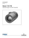
Model DO-03/04
Dissolved Oxygen Measurement System
with Air Blast Cleaner
ESSENTIAL INSTRUCTIONS
READ THIS PAGE BEFORE PROCEEDING!
Rosemount Analytical designs, manufactures, and tests its products to
meet many national and international standards. Because these instruments are sophisticated technical products, you must properly install, use,
and maintain them to ensure they continue to operate within their normal
specifications. The following instructions must be adhered to and integrated into your safety program when installing, using, and maintaining
Rosemount Analytical products. Failure to follow the proper instructions
may cause any one of the following situations to occur: Loss of life; personal injury; property damage; damage to this instrument; and warranty
invalidation.
• Read all instructions prior to installing, operating, and servicing the product. If this Instruction Manual is not the correct manual, telephone 1800-654-7768 and the requested manual will be provided. Save this
Instruction Manual for future reference.
• If you do not understand any of the instructions, contact your
Rosemount representative for clarification.
• Follow all warnings, cautions, and instructions marked on and supplied
with the product.
• Inform and educate your personnel in the proper installation, operation,
and maintenance of the product.
• Install your equipment as specified in the Installation Instructions of the
appropriate Instruction Manual and per applicable local and national
codes. Connect all products to the proper electrical and pressure
sources.
• To ensure proper performance, use qualified personnel to install, operate, update, program, and maintain the product.
• When replacement parts are required, ensure that qualified people use
replacement parts specified by Rosemount. Unauthorized parts and
procedures can affect the product’s performance and place the safe
operation of your process at risk. Look alike substitutions may result in
fire, electrical hazards, or improper operation.
• Ensure that all equipment doors are closed and protective covers are in
place, except when maintenance is being performed by qualified persons, to prevent electrical shock and personal injury.
WARNING
ELECTRICAL SHOCK HAZARD
Making cable connections to and servicing this instrument require access to shock hazard level voltages
which can cause death or serious injury, therefore,
disconnect all hazardous voltage before accessing
the electronics.
Relay contacts made to separate power sources must
be disconnected before servicing.
Electrical installation must be in accordance with the
National Electrical Code (ANSI/NFPA-70) and/or any
other applicable national or local codes.
Unused cable conduit entries must be securely sealed
by non-flammable closures to provide enclosure
integrity in compliance with personal safety and environmental protection requirements. Use NEMA 4X or
IP65 conduit plugs supplied with the instrument to
maintain the ingress protection rating (IP65).
For safety and proper performance this instrument
must be connected to a properly grounded three-wire
power source.
Proper relay use and configuration is the responsibility of the user. No external connection to the instrument of more than 60VDC or 43V peak allowed with
the exception of power and relay terminals. Any violation will impair the safety protection provided.
Do not operate this instrument without front cover
secured. Refer installation, operation and servicing to
qualified personnel.
WARNING
This product is not intended for use in the residential, commercial or light industrial environment per
certification to EN61326.
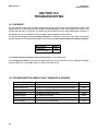
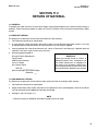
About This Document
This manual contains instructions for installation and operation of the Model DO-03/04. The following
list provides notes concerning all revisions of this document.
Rev. Level
Date
A
1/04
This is the initial release of the product manual. The manual has been reformatted to reflect the
Emerson documentation style and updated to reflect any changes in the product offering.
B
5/04
Drawings and part numbers were updated on pages 5, 6, 7, and 51.
C
10/04
Updated Specifications, Section 1.0.
Emerson Process Management
Rosemount Analytical Inc.
2400 Barranca Parkway
Irvine, CA 92606 USA
Tel: (949) 757-8500
Fax: (949) 474-7250
http://www.raihome.com
© Rosemount Analytical Inc. 2004
Notes
MODEL DO-03/04
TABLE OF CONTENTS
MODEL DO-03/04 MEASURING SYSTEM
TABLE OF CONTENTS
Section Title
Page
1.0
1.1
1.2
1.3
SPECIFICATIONS...................................................................................................
Features and Applications .......................................................................................
Specifications...........................................................................................................
Ordering Information................................................................................................
1
1
2
6
2.0
2.1
2.2
INSTALLATION.......................................................................................................
Unpacking and Inspection .......................................................................................
Installation................................................................................................................
7
7
7
3.0
3.1
3.2
3.3
WIRING ...................................................................................................................
General ....................................................................................................................
Power, Alarm, and Output Wiring ............................................................................
Sensor Wiring ..........................................................................................................
12
12
12
16
4.0
4.1
4.2
4.3
DISPLAY AND OPERATION...................................................................................
Display .....................................................................................................................
Key Functions and Control ......................................................................................
Alarm Status ............................................................................................................
17
17
17
17
5.0
5.1
5.2
5.3
5.4
5.5
5.6
5.7
5.8
5.9
5.10
5.11
5.12
SOFTWARE CONFIGURATION .............................................................................
Changing Alarm Setpoints .......................................................................................
Ranging the Outputs................................................................................................
Testing Outputs and Alarms ....................................................................................
Choosing Display Options .......................................................................................
Changing Output Parameters..................................................................................
Changing Alarm Parameters ...................................................................................
Temperature Compensation and Temperature Units...............................................
Noise Reduction ......................................................................................................
Barometric Pressure................................................................................................
Main Sensor Calibration Parameters ......................................................................
Security....................................................................................................................
Analyzer Mode Priority ............................................................................................
18
24
25
26
27
29
31
35
36
37
38
39
40
6.0
6.1
6.2
CALIBRATION - TEMPERATURE..........................................................................
Introduction ..............................................................................................................
Temperature Calibration ..........................................................................................
41
41
42
7.0
7.1
7.2
7.3
7.4
7.5
CALIBRATION - DISSOLVED OXYGEN................................................................
Introduction ..............................................................................................................
Zeroing the Sensor ..................................................................................................
Calibrating the Sensor in Air....................................................................................
Calibrating the Sensor Against a Standard Instrument ...........................................
Calibrating Barometric Pressure..............................................................................
43
43
44
45
47
48
8.0
8.1
8.2
CALIBRATION - CURRENT OUTPUTS .................................................................
Introduction ..............................................................................................................
Trimming the Outputs ..............................................................................................
49
49
49
i
MODEL DO-03/04
TABLE OF CONTENTS
TABLE OF CONTENTS (CONTINUED)
Section
Title
Page
9.0
9.1
9.2
9.3
9.4
MAINTENANCE ......................................................................................................
Analyzer (Model 54eA-01).......................................................................................
Oxygen Sensor (Model 499ADO-54) ......................................................................
Air Compressor........................................................................................................
Air Blast Sensor Washer .........................................................................................
50
50
50
52
53
10.0
10.1
10.2
10.3
10.4
10.5
10.6
10.7
TROUBLESHOOTING ............................................................................................
Overview..................................................................................................................
Troubleshooting When a Fault Message is Showing ..............................................
Troubleshooting When No Fault Message is Showing - Temperature ....................
Troubleshooting When No Fault Message is Showing - Oxygen............................
Troubleshooting Not Related to Measurement Problems .......................................
Simulating Inputs - Dissolved Oxygen.....................................................................
Simulating Temperature...........................................................................................
54
54
54
56
56
59
59
60
11.0
RETURN OF MATERIALS......................................................................................
61
LIST OF TABLES
Table No.
5-1
5-2
9-1
Title .........................................................................................................................
Program Settings List ..............................................................................................
Controller Mode Priority Chart.................................................................................
Replacment Parts ....................................................................................................
ii
Page
21
40
50
MODEL DO-03/04
TABLE OF CONTENTS
LIST OF FIGURES
Section
1-1
Title
Page
Suggested Arrangement of Handrail Mounting Assembly, Maintenance Clamp,....
Air Compressor Enclosure, and 54eA Analyzer ......................................................
4
1-2
Analyzer Dimensions...............................................................................................
4
1-3
Enclosure Dimensions.............................................................................................
5
1-4
Standard Sensor with Integral Cable.......................................................................
5
1-5
Air Blast Washer Head ............................................................................................
5
2-1
Suggested Arrangement of Handrail Mounting Assembly, Maintenance Clamp,....
Air Compressor Enclosure, and 54eA Analyzer ......................................................
8
2-2
Pipe Mounting..........................................................................................................
8
2-3
Attaching the Air Compressor Enclosure to the Handrail........................................
10
2-4
Assembling and Attaching the Handrail Mounting Assembly ..................................
10
2-5
Installing the Sensor in the Washer Head Assembly ..............................................
11
3-1
Power Input, Relay, and Output Wiring for 54eA Analyzer......................................
13
3-2
Model DO-03 — Wiring Air Blast Compressor to Model 54eA Analyzer 115 Vac ..
14
3-3
Model DO-04 — Wiring Air Blast Compressor to Model 54eA Analyzer 230 Vac..
15
3-4
Wiring Label.............................................................................................................
16
3-5
Oxygen Sensor with Standard Cable ......................................................................
16
3-6
Oxygen Sensor with Optimum EMI/RFI Cable or Variopol Cable ...........................
16
4-1
Main Display Screen................................................................................................
17
5-1
Menu Tree for the 54eA Analyzer............................................................................
18
5-2
Low Alarm................................................................................................................
32
5-3
High Alarm ...............................................................................................................
32
5-4
Interval Timer ..........................................................................................................
34
7-1
Sensor Current as a Function of Dissolved Oxygen Concentration .......................
43
9-1
Sensor Parts ............................................................................................................
52
9-2
Replacement Parts ..................................................................................................
53
10-1
Simulate Dissolved Oxygen.....................................................................................
59
10-2
Three-Wire RTD Configuration................................................................................
60
10-3
Simulating RTD Inputs.............................................................................................
60
iii
MODEL DO-03/04
SECTION 1.0
SPECIFICATIONS
SECTION 1.0
SPECIFICATIONS
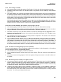
• COMPLETE SYSTEM INCLUDES sensor, analyzer, sensor washer head, mounting hardware, and air compressor.
• AIR BLAST CLEANER system can keep DO sensors
longer.
funtioning up to 3 months or
• SENSOR MAINTENANCE is quick and easy.
• FEATURE-PACKED ANALYZER: on-board pressure sensor for completely automatic air
calibration, large backlit display, dual outputs, three fully programmable alarm relays.
FEATURES AND BENEFITS
The Model DO-03/04 is a complete system for the determination of dissolved oxygen in wastewater aeration
basins. It consists of a sensor, an analyzer, a handrail mounting assembly, a sensor washer head, and an air
compressor. A timer in the analyzer allows the user to customize the air blast cleaning cycle.
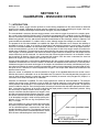
The Model DO-03/04 uses a membrane-covered amperometric sensor. A polarizing voltage applied to a gold
cathode behind the membrane destroys oxygen diffusing through the membrane and keeps the concentration of
oxygen in the sensor equal to zero. The current generated by the cathode reaction is proportional to the rate of
diffusion of oxygen through the membrane. Because the concentration of oxygen in the sensor is zero, the diffusion rate and the current are proportional to the concentration of oxygen in the sample.
Sensor maintenance is fast and easy. Replacing a membrane requires no special tools or fixtures. A screw cap
holds the pre-tensioned membrane in place. Replacing the electrolyte solution takes only minutes.
The Model DO-03/04 includes the rugged, easy-to-use Model 54eA analyzer. The analyzer features two fully programmable 4-20 mA outputs, and three fully programmable alarm relays. The backlit three line display allows the
user to read oxygen levels at a glance. The analyzer permits both air calibration and calibration against a laboratory instrument. Air calibration is completely automatic. All the user does is expose the sensor to water-saturated
air and press a few buttons.
The Air Blast Sensor Cleaner, which includes the washer head and air compressor, keeps the sensor membrane
clean, helping ensure reliable, trouble-free oxygen measurements and reducing sensor cleaning maintenance to
as little as every three months. At programmed intervals, the air blast cleaner blows a stream of air across the
membrane to clear bio-film from on the membrane. The frequency and duration of the air blast is programmable
from the 54eA analyzer.
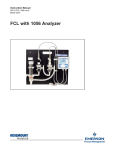
The photograph shows a sensor after nine weeks in an aeration basin. The cathode is clearly visible under the
membrane. A 60-second air blast every eight hours is keeping the membrane clean.
Plant service air can be used in place of the air compressor. The 54eA analyzer relay is then used to operate a
solenoid valve.
1
MODEL DO-03/04
SECTION 1.0
SPECIFICATIONS
Cathode: Gold (not normally wetted)
Outputs: Two 4-20 mA or 0-20 mA isolated outputs.
Continuously adjustable. Outputs can be assigned
to oxygen or temperature. Output dampening is
user-selectable. Maximum load at 100/200 Vac is
550 ohms.
Accuracy: ±0.2 ppm at 25°C
Output Accuracy: ± 0.05 mA
Repeatability: ±0.05 ppm 25°C
Alarms: Relays 1, 2, and 3 are assignable to oxygen
or temperature. One relay can also be used as
an interval timer to operate the air blast cleaner.
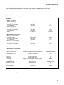
SPECIFICATIONS - 499ADO-54 SENSOR
Range: 0 to 20 ppm (mg/L)
Wetted parts: Noryl1 Viton2 EPDM, Teflon3, silicone
Response time: 25 sec to 63% of final reading at 25°C
Pressure: 0 to 65 psig (0 to 549 kPa abs)
Temperature: 32 to 122°F (0 to 50°C)
Process connection: 1 inch MNPT
Electrolyte volume: 25 mL (approx.)
Cable length (standard): 25 ft (7.6 m)
Relay 4 - Sensor/analyzer fault alarm
Each relay has a dedicated LED on the front panel.
Relay Contacts: Relays 1-3: Epoxy sealed form A
contacts, SPST, normally open
Relay 4: Epoxy sealed form C, SPDT
Resistive
Inductive
115 Vac
5.0 Amps
3.0 Amps
230 Vac
5.0 Amps
1.5 Amps
Cable length (maximum): 300 ft (91 m)
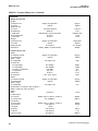
SPECIFICATIONS - 54EA-01 ANALYZER
Enclosure: Epoxy-painted (light gray) cast aluminum,
NEMA 4X (IP65). 144 x 144 x 132 mm
(5.7 x 5.7 x 5.2 in.), DIN size panel cut-out.
Front Panel: Membrane keypad with tactile feedback.
Three green LEDs indicate alarm status. Red
LED indicates fault condition.
Display: Three-line, back-lit, dot matrix LCD, 70 x 35 mm.
First line is oxygen reading. Second line is temperature and current output. Third line is userselectable. Character heights: 1st line - 16 mm
(0.6 in.), 2nd and 3rd lines - 7 mm (0.3 in.).
Power:
115 VAC ± 10%, 50/60 Hz ± 6%, 8 W
230 VAC ± 10%, 50/60 Hz ± 6%, 8 W
RFI/EMI: EN-61326
LVD: EN-61010-1
2
Ambient Temperature: 0 to 50°C (32 to 122°F).
Analyzer can be operated between -20 and 60°C
(-4 to 140°F) with some degradation in display
quality.
Relative Humidity: 95% (maximum) non-condensing
Temperature correction for membrane permeability:
automatic between 0 and 50°C.
Calibration: automatic air calibration or calibration
against a standard instrument
Pressure sensor range: 113 to 862 mm Hg (150 to
1150 mbar)
1Noryl is a registered trademark of General Electric
2Viton is a registered trademark of E.I. duPont de Nemours & Co.
3Teflon is a registered trademark of E.I. duPont de Nemours & Co.
MODEL DO-03/04
SECTION 1.0
SPECIFICATIONS
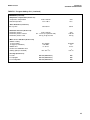
SPECIFICATIONS - COMPRESSOR FOR
AIR BLAST CLEANER SYSTEM
SPECIFICATIONS - HANDRAIL MOUNTING
ASSEMBLY
Enclosure: Fiberglass reinforced polyester with polyester cover, NEMA 4x (IP65). 11.9 x 11.9 x 6.9 in
(302 x 302 x 175 mm).
Materials of Construction:
Compressor: Oil-less, non-lubricating piston and
cylinder. 1/12 HP permanent split capacitor motor
with thermal overload protection.
Maximum continuous pressure: 50 psig
(446 kPa abs)
Weather cap: Schedule 40 PVC
Pipe clamp and bracket: Aluminum
Clevis: zinc-plated steel
U-bolts, nuts, and bolts: zinc-plated steel
Washers: stainless steel
Operating pressure: 20 psig (239 kPa abs)
Air hose: 25 ft (7.6 m) included with ABSH
Ambient temperature: 5 to 122°F (-15 to 50°C)
assuming intermittent operation
Power:
Code -03: 115 VAC, 60 Hz or 100
VAC, 50/60 Hz, single phase,1.3 to
1.4 A, starting current 3.88 A, insulation class B; UL approved
Code -04: 220 VAC, 50 Hz, single
phase, 0.6 A, starting current 1.5 A,
insulation class A; CE approved
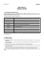
SHIPPING INFORMATION
The Model DO-03/04 is shipped in a single container.
Shipping weight is 38 lbs (17.5 kg).
PLANT AIR SYSTEM REQUIREMENTS
(for customers using plant air in place of
air compressor)
Pressure: 20 psig (239 kPa abs)
Flow: 0.50 SCFM (14 L/min at STP)
SPECIFICATIONS - AIR BLAST CLEANER
SYSTEM WASHER HEAD
Air hose: (customer supplied) compatible with ¼ inch
barbed fitting for connection at washer head
Process connection: 1-1/2 inch PVC pipe socket
Dimensions (diameter x length): 2-1/2 x 10-3/4
inches (64 x 273 mm)
Wetted materials: PVC, Noryl, Viton
Pipe boom: 1-1/2 inch schedule 80 PVC, maximum
length 12 feet (3.6 m) past handrail mounting clamp.
Pipe boom is supplied by customer.
Maximum distance between compressor and sensor:
25 ft (7.6 m). ABSH is supplied with 25 ft (7.6 m) of air
hose.
3
MODEL DO-03/04
SECTION 1.0
SPECIFICATIONS
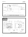
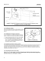
FIGURE 1-1. Suggested arrangement of handrail mounting assembly, maintenance clamp,
air compressor enclosure, and 54eA analyzer
WHEN INCH AND METRIC DIMS
ARE GIVEN
MILLIMETER
INCH
FIGURE 1-2. Analyzer dimensions
4
MODEL DO-03/04
SECTION 1.0
SPECIFICATIONS
WHEN INCH AND METRIC DIMS
ARE GIVEN
INCH
MILLIMETER
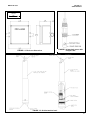
FIGURE 1-3. Enclosure dimensions
FIGURE 1-4. Standard sensor with
integral cable
FIGURE 1-5. Air blast washer head
5
MODEL DO-03/04
SECTION 1.0
SPECIFICATIONS
ORDERING INFORMATION
The Model DO -03/04 is a complete system for the determination of oxygen in wastewater aeration basins. It
consists of a 54eA analyzer, a 499ADO-54 oxygen sensor, an air blast washer head with air compressor and
hose, and a handrail mounting bracket. All hardware necessary to mount the analyzer and the air compressor
enclosure on a handrail is provided. Cable gland fittings for the analyzer are also supplied. Three replacement
membranes and a bottle of electrolyte solution are shipped with the sensor. Pipe boom is supplied by customer.
MODEL DO DISSOLVED OXYGEN MEASURING SYSTEM WITH AIR BLAST CLEANER
MODEL
DO
Description
Dissolved Oxygen Measuring System
CODE
Power (required selection)
-03
115 Vac, 60 Hz or 100 Vac, 50/60 Hz
-04
220 Vac, 50 Hz
DO -03
EXAMPLE
ACCESSORIES FOR 54eA ANALYZER
Part #
9240048-00
DESCRIPTION
Tag, stainless steel, specify marking
CONSUMABLES FOR SENSOR
Part #
23502-00
9210264
DESCRIPTION
Membrane replacement kit with O-ring, qty 3
Amperometric sensor fill solution #1, 4 oz (120 mL)
Customers using plant compressed air should order the following items in place of Model -03/04:
54e-A-01
2002577
23554-00
499ADO-54
24057-00
HRMS-02
9320101
24049-00
9160549
Model 54eA analyzer
Mounting bracket for Model 54e, pipe/wall
Cable glands kit for Model 54e, qty 5
Model 499ADO oxygen sensor
Smooth membrane retainer for 499ADO sensor
Handrail clamp assembly for washer head (clamp, sensor maintenance kit, and elbow)
Elbow, 90° female socket, PVC schedule 40
Air blast washer head
Air hose, 1/4-inch ID x 1/2-inch OD, 25 ft (7.6 m)
REPLACMENT PARTS AND ACCESSORIES
9380088
9380089
24051-00
Air compressor; 115 Vac, 60 Hz or 100 Vac, 50/60 Hz
Air compressor; 220 Vac, 50 Hz
Mounting hardware for air compressor enclosure
24053-00
O-ring kit for sensor washer head (three O-rings and lube)
6
MODEL DO-03/04
SECTION 2.0
INSTALLATION
SECTION 2.0
INSTALLATION
2.1 UNPACKING AND INSPECTION
Inspect the shipping container. If it is damaged, contact the shipper immediately for instructions. If there is no
apparent damage, unpack the container. Be sure all items shown on the packing list are present. If items are
missing, notify Rosemount Analytical immediately.
The Model DO-03/04 consists of the following items.
Model or part number
Description
54e-A-01
Model 54eA analyzer
2002577
Mounting bracket for Model 54e, pipe/wall
23544-00
Cable glands kit for Model 54e, qty 5
499ADO-54
Model 499ADO oxygen sensor
24057-00
Smooth membrane retainer for 499ADO sensor
HRMS-02
Handrail clamp assembly (clamp, sensor maintenance kit, and elbow)
24049-00
Air blast washer head
24050-00
Air compressor and enclosure with air hose (115 VAC) option -03 only
24050-01
Air compressor and enclosure with air hose (220 VAC) option -04 only
24051-00
Mounting hardware for air compressor enclosure
24053-00
O-ring kit for sensor washer head (three O-rings and lube)
The customer must supply a schedule 80 1-1/2 inch PVC pipe boom to immerse the sensor and cleaning head in
the aeration basin.
2.2 INSTALLATION
2.2.1 General information
1. Although the equipment is suitable for outdoor use, do not install it in direct sunlight or in areas of extreme
temperatures.
2. Install the equipment in an area where vibrations and electromagnetic and radio frequency interference are
minimized or absent.
3. To keep the analyzer watertight, install plugs (provided) in the unused cable openings.
4. Keep the analyzer and sensor wiring at least one foot from high voltage conductors. Be sure there is easy
access to the analyzer.
5. Provide room to allow the sensor and attached piping to be removed from the aeration basin for service. A
maintenance bracket (part of PN 24048-00) can be used to rest the PVC pipe boom on the handrail.
Figure 2-1 shows the suggested arrangement of the analyzer, air compressor, and maintenance bracket on the
handrail.
7
MODEL DO-03/04
SECTION 2.0
INSTALLATION
FIGURE 2-1. Suggested arrangement of handrail mounting assembly, maintenance clamp,
air compressor enclosure, and 54eA analyzer.
2.2.2 Installing the analyzer
When used in Model DO-03/04, the 54eA analyzer is intended to be mounted on the basin handrail. See Figures 2-1
and 2-2.
2.2.3 Installing the air compressor enclosure
The air compressor is in a NEMA 4X fiberglass enclosure.
Figure 2-3 shows how to attach the enclosure to a handrail.
1. Locate the enclosure within 25 ft (7.6 m) of the sensor.
2. Be sure the ambient temperature is between 5 and
122°F (-15 to 50°C). Do not expose the enclosure to
direct sunlight. The operating temperature for the air
compressor might be exceeded.
FIGURE 2-2. Pipe Mounting
2.2.4 Installing the handrail mounting assembly
The handrail mounting assembly (PN 24048-00) is shipped completely disassembled. Assemble and attach the
mounting assembly to the handrail. Refer to Figure 2-4. The spring pin shipped with the handrail mounting
assembly is not needed. Do not attach the boom clamp to the clevis yet. Attach the maintenance bracket (PN
24044-00) to the handrail. See Figure 2-1.
2.2.5 Assembling the pipe and pipe clamp
Slide the PVC pipe boom through the handrail mounting pipe clamp. Tighten the bolt to keep the clamp from
sliding off. Use 1-1/2 inch schedule 80 PVC piping. Distance between the clamp and the end of the pipe should
not exceed 12 feet (3.6 m). See Figures 2-1 and 2-4.
8
MODEL DO-03/04
SECTION 2.0
INSTALLATION
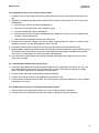
2.2.6 Installing the sensor in the washer head assembly
1. Remove the sensor from its box. Remove the plastic protective cap from the end of the sensor. Save the
cap.
2. Replace the knurled cap provided with the sensor with the smooth cap (PN 33521-01). The smooth cap is
shipped loose.
a. Hold the sensor with the membrane end pointing up.
b. Unscrew the knurled cap. Leave the membrane in place.
c.
Screw the smooth cap in place. Hand tighten.
d. Hold the sensor with the membrane end pointing down. Shake the sensor a few times as though shaking down a clinical thermometer.
e. Slide the protective cap back over the end of the sensor.
3. Remove the set screw at the bottom of the sensor washer head assembly. See Figure 2-5. Pull the washer
head from the shank. You are pulling against a dual O-ring seal.
4. Press the metal tab on the air hose quick connect fitting and remove the fitting and check valve.
5. Wrap the bottom facing threads of the sensor with pipe tape. Remove the protective cap and slide the O-ring
(PN 9550291) over the end of the sensor until it rests against the lower edge of the bottom facing thread.
The O-ring is in a bag taped to the side of the washer head assembly.
6. Screw the sensor into the bottom of the washer assembly. Hand tighten only. Replace the air hose and
check valve assembly.
2.2.7 Assembling the washer head and pipe boom
1. Cement the upper portion of the washer assembly head to the PVC pipe boom. See Figure 2-5. Use 1-1/2
inch schedule 80 PVC pipe. Press (do not cement) the PVC elbow (PN 9320101) to the top of the pipe
boom. The elbow keeps water from collecting in the pipe boom.
2. Pass the sensor cable and air hose through the boom and elbow.
3. Connect the end of the air hose to the barbed fitting on the check valve.
4. Push the washer head back onto the shank. Use a small amount of grease to lubricate the O-rings. Replace
and tighten the set screw.
2.2.8 Attaching the pipe boom to the handrail mounting assembly
1. Slide the tongue of the pipe clamp into the clevis. Insert the bolt as shown in Figure 2-3.
2. Rest the boom on the maintenance bracket until ready to submerge the sensor in the basin.
9
MODEL DO-03/04
SECTION 2.0
INSTALLATION
FIGURE 2-3. Attaching the air compressor enclosure to the handrail
FIGURE 2-4. Assembling and attaching the handrail mounting assembly.
The spring pin (not shown) shipped with the handrail mounting assembly is not used.
10
MODEL DO-03/04
SECTION 2.0
INSTALLATION
FIGURE 2-5. Installing the sensor in the washer head assembly
11
MODEL DO-03/04
SECTION 3.0
WIRING
SECTION 3.0
WIRING
3.1 GENERAL
WARNING
Electrical installation must conform to the National Electrical Code, all state and local codes, and all plant
codes and standards for electrical equipment. Electrical installation and wiring must be done by qualified
personnel.
The five holes in the bottom of the Model 54eA enclosure accept 1/2-in. (PG-13.5) strain relief connectors or conduit fittings. The rear openings are for power and alarm relay wiring. The left front opening is for sensor wiring and
the right front opening is for analog output wiring. Seal unused openings with conduit plugs.
3.2 POWER, ALARM, AND OUTPUT WIRING
Figure 3-1 shows the power, relay, and current output terminals. For access to the terminals, loosen the screw holding the protective cover in place and remove the cover. Make power and alarm connections on TB3. Make analog
output wiring connections on TB2.
DANGER
Live voltages may be present.
Will cause severe injury or death.
Alarm contacts are dry (i.e., not powered) and are normally open. Refer to Section 1.0 for relay specifications.
Refer to Figure 3-2 or 3-3 for details on how to wire the Model ABSH (air blast system) to the 54eA analyzer. Figure
3-2 is for Model DO-03 (115 Vac 60 Hz). Figure 3-3 is for Model DO-04 (220 Vac 50 Hz).
NOTE
The 54eA analyzer has four alarm relays. Relays 1, 2, or 3 are normally open (NO) and can be used to
operate the air blast cleaner. The wiring diagrams show alarm relay 3 being used. The relay used for the
air blast cleaner MUST be configured as an interval timer. See Section 5.6 for programming details.
For best EMI/RFI protection, shield the output cable and enclose it in an earth-grounded, rigid, metal conduit.
Connect the outer shield of the output cable to the earth ground connection on TB2 (see Figure 3-1).
Keep sensor and output signal wiring separate from power wiring. Do no run sensor and power cables in the same
conduit or close together in a cable tray.
AC wiring must be 14 gauge or greater. Be sure to connect earth ground from the power cable to the nearby
ground lug. A good earth ground is necessary for proper operation of the analyzer. Provide a switch or breaker to
disconnect the analyzer from the main power supply. Install the switch or breaker near the analyzer and label it as
the disconnecting device.
WARNING: RISK OF ELECTRICAL SHOCK
AC connections and grounding must comply with UL 508 or local electrical code. DO NOT apply
power to the analyzer until all electrical connections are verified and secure.
12
MODEL DO-03/04
SECTION 3.0
WIRING
DWG. NO.
454EPH02
REV.
D
FIGURE 3-1. Power Input, Relay, and Output Wiring for 54eA analyzer
13
MODEL DO-03/04
SECTION 3.0
WIRING
FIGURE 3-2. Model DO-03 — Wiring Air Blast Compressor to Model 54eA Analyzer 115 Vac
14
MODEL DO-03/04
SECTION 3.0
WIRING
FIGURE 3-3. Model DO-04 — Wiring Air Blast Compressor to Model 54eA Analyzer 230 Vac
15
MODEL DO-03/04
SECTION 3.0
WIRING
3.3 SENSOR WIRING
3.3.1 General
The wiring label, which is shown in Figure 3-4,
is a general purpose label. It has wiring information concerning other sensors, for example,
contacting conductivity and pH, that can be
used with the 54eA instrument platform. For
the measurement of oxygen only terminal strip
TB3 is used.
3.3.2 Wiring the Oxygen Sensor
Figure 3-5 shows how to wire the oxygen sensor to the analyzer.
Although it is not standard with the Model DO03/04, an optional quick disconnect (Variopol)
sensor and cable are available. Figure 3-6
shows how to wire this sensor to the analyzer.
DWG. NO.
40054e03
FIGURE 3-4. Wiring Label
DWG. NO.
REV.
40499A23
A
FIGURE 3-5. Oxygen sensor
with standard cable.
16
DWG. NO.
40499A24
REV.
A
FIGURE 3-6. Oxygen sensor with optimum
EMI/RFI cable or Variopol cable.
REV.
A
MODEL DO-03/04
SECTION 4.0
DISPLAY AND OPERATION
SECTION 4.0
DISPLAY AND OPERATION
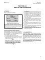
4.1 DISPLAY
Figure 4-1 shows the main display.
1.00 ppm
26.2°C.
ALI: 0.50
12.00 mA
I: 3200 nA
FIGURE 4-1. Main Display Screen
The concentration of oxygen is displayed continuously in
large numerals. The temperature and output current are
displayed on the second line. The third line can be configured by the user. In the example the third line shows the
alarm 1 setpoint and the sensor current.
3. Press Enter (F4) to access a sub-menu or an item
in a sub-menu.
4. To change a number or a setting press Edit (F4).
The display will change to show the cursor on the
first digit or on a + or - sign. Use the and keys
to increase or decrease a digit or to toggle the +
and - signs. Use the and keys to move the
cursor left and right.
5. If an entire number or a word is highlighted, use the
and keys to scroll through the list of choices.
6. To store a number or setting in memory, press
Save (F4).
7. To leave without storing changes, press Esc (F3).
8. To leave and return to the previous screen, press
Exit (F1).
9. To end a calibration step and leave the previous
calibration in place, press Abort (F1).
10. Occasionally, information screens will appear. To
leave the information screen and move to the next
screen press Cont (F3).
4.2 KEY FUNCTIONS AND CONTROL
The keys labeled F1, F2, F3, and F4 are multi-function.
The function appears in the main display just above the
key. For example, F1 is usually labeled Exit and F4
may be labeled Edit, Save, or Enter.
1. To enter the main menu, press any key.
2. Use the and keys to move the cursor to the
desired sub-menu. The position of the cursor is
shown in reverse video.
NOTE
When the last item of a menu has been
reached, the cursor will be on the third line
of the display. If the cursor is on the second
line of the display more items remain.
Continue pressing the key.
4.3 ALARM STATUS
Green LEDs (labeled 1, 2, and 3) indicate when alarm
relays 1, 2, and 3 are energized. The fourth relay indicates a fault condition. When a fault occurs, the red
LED (labeled FAIL) lights up, a descriptive error message appears, and the outputs and alarm relays act as
described in Section 5.5 and Section 5.6 under fault
value.
The red LED also indicates when the interval timer routine is activated and when the time limit has been
reached on a feed limit timer. For more information on
these subjects, see Section 5.6.
17
MODEL DO-03/04
SECTION 5.0
SOFTWARE CONFIGURATION
SECTION 5.0
SOFTWARE CONFIGURATION
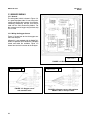
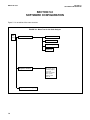
Figure 5-1 is an outline of the menu structure.
FIGURE 5-1. Menu Tree for the 54eA Analyzer
Main
Menu
Calibrate
Calibrate main sensor
Zero main sensor
Adjust temperature
Output trim
Diagnostic Variables
Program (see following page)
18
Main measurement
Main sensor current
Sensitivity (μA/ppm)
Zero current
Barometric pressure
Noise rejection
Software version
Device ID
MODEL DO-03/04
SECTION 5.0
SOFTWARE CONFIGURATION
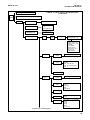
FIGURE 5-1. Menu Tree for the 54eA Analyzer
(continued)
Calibrate (see previous page)
Main
Menu
Diagnostic Variable (see previous page)
Program
Alarm Setpoints
Alarms 1, 2, and 3 setpoints
Output setpoints
4 mA or 0 mA
20 mA
Present output current
Simulated tests
Test output 1 or 2
Test alarm 1, 2, 3, or 4
Configure
Display
Main
Sensor
Oxygen
Sensor type and manufac.
Units: ppm, ppb, % sat
°C or °F
Output 1 (mA or %FS)
Output 2 (mA or %FS)
Language
Line 3 display
Display contrast
Timeout (on or off)
Timeout - limit
Polling address
Outputs
Output 1 and 2
control
Output 1 and 2
setup
Measurement: main snr, temp.
Range (0-20 or 4-20 mA)
Dampen
Hold - keep last value
Hold - go to specified value
Fault
Hold feature setup
Alarms
Alarm 1, 2, & 3
control
Alarm 1, 2, & 3
setup
Measurement: main snr, pH, temp.
Alarm: High, low, or off
Setpoint
Hysteresis
Delay
Relay default
Alarm 4 setup
Feed limit timer
Interval timer
Feed limit: Alarm 1, 2, or 3 or disable
Timeout
Timer: Alarm 1, 2, or 3 or disable
Interval
Repeats
On time
Off time
Recovery time
Continued on following page
19
MODEL DO-03/04
SECTION 5.0
SOFTWARE CONFIGURATION
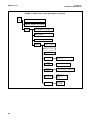
FIGURE 5-1. Menu Tree for the 54eA Analyzer (continued)
Main
Menu
Calibrate (see page 16)
Diagnostic Variable (see page 16)
Program
Alarm Setpoints (see page 17)
Output setpoints (see page 17)
Simulated tests (see page 17)
Configure
Display (see page 17)
Outputs (see page 17)
Alarms (see page 17)
Temperature
Noise
Rejection
Barometric
Pressure
20
Temperature comp: auto or manual
Units: °C or °F
Noise rejection: 50 or 60 Hz
Measurement: Auto or manual
Units: mm Hg, kPa, atm, barg, in Hg
Main sensor cal
Stabilize conc’n
Stabilize time
Salinity
Security
Lock all
Lock program
Lock configure
MODEL DO-03/04
SECTION 5.0
SOFTWARE CONFIGURATION
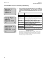
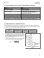
Table 5-1 lists the default settings and the range of choices available for each setting. To reduce the chance of
error when configuring the analyzer the first time, enter settings in the order shown in the table.
TABLE 5-1. Program Settings List
ITEM
SETPOINTS
A. Alarms (Section 5.1)
1. Alarm 1 (low action)
a. if oxygen (ppm)
b. if oxygen (% saturation)
c. if temperature
2. Alarm 2 (high action)
a. if oxygen (ppm)
b. if oxygen (% saturation)
c. if temperature
3. Alarm 3
B. Outputs (Section 5.2 and 5.3)
1. Output 1 or 2: 4 mA setting
a. if oxygen (ppm)
b. if oxygen (% saturation)
c. if temperature
2. Output 1 or 2: 20 mA setting
a. if oxygen (ppm)
b. if oxygen (% saturation)
c. if temperature
CONFIGURE
A. Display options (Section 5.4)
1. Measurement
2. Sensor (Oxygen only)
3. Units (Oxygen only)
4. Temperature units
5. Output 1
6. Output 2
7. Language
8. Main display left
9. Main display right
10 Display contrast
11. Test timeout
12. Timeout value
CHOICES
FACTORY SETTINGS
-99 to 99 ppm
0 to 200%
-5 to 130°C
0 ppm
0%
0.1°C
-99 to 99 ppm
0 to 200%
-5 to 130°C
See alarm 2
20 ppm
200 %
130°C
See alarm 2
-99 to 99 ppm
0 to 200%
-5 to 130°C
0 ppm
0%
0.1°C
-99 to 99 ppm
0 to 200%
-5 to 130°C
20 ppm
200%
130°C
Oxygen, ozone, free chlorine, total chlorine
Rosemount standard, Rosemount biopharm, or
other steam sterilizable
ppm, ppb, % saturation
°C or °F
mA or % of full scale
mA or % of full scale
English, Français, Español, Deutsch, Italiano
See section 5.5
See section 5.5
00-99 (darkest)
On or off
1 to 60 min
Oxygen
Rosemount standard
ppm
°C
mA
mA
English
Sensor current
Output 1 current
50
On
10 min
Continued on the following page
21
MODEL DO-03/04
SECTION 5.0
SOFTWARE CONFIGURATION
TABLE 5-1. Program Settings List (continued)
ITEM
CONFIGURE
B Outputs (Section 5.5)
1. Output 1
a. Measurement
b. Control
2. Output 1 Setup
a. Current
b. Dampening
c. Hold mode
d. Fixed hold value
e. Fault value
3. Output 2
a. Measurement
b. Control
4. Output 2 Setup
5. Hold feature
CHOICES
FACTORY SETTINGS
Oxygen or temperature
Normal
Oxygen
Normal
4-20 mA or 0-20 mA
0-299 sec
Hold last value or go to fixed value
0-22 mA
0-22 mA
4-20 mA
0 sec
Hold last value
21 mA
22 mA
Oxygen or temperature
Normal
See output 1
Enable, disable, or 20 min timeout
Temperature
Normal
See output 1
Disable
C. Alarms (Section 5.6)
1. Alarm 1
a. Activation method
Oxygen or temperature
b. Control mode
Normal
2. Alarm 1 setup
a. Configuration
Low, high, or off
b. Hysteresis
if oxygen (ppm)
0 to 20 ppm
if oxygen (ppb)
0 to 999 ppb
if oxygen (% saturation)
0 to 200%
if temperature
0 to 10°C
c. Delay time
0-99 sec
d. Relay fault
none, open, closed
3. Alarm 2
a. Activation method
Oxygen or temperature
b. Control mode
Normal
4. Alarm 2 setup
a. Configuration
Low, high, or off
Rest of alarm 2 setup is the same as alarm 1
5. Alarm 3 setup is the same as alarm 1
6. Alarm 4
Alarm
Fault or off
7. Feed limit timer
a. Feed limit
Disable, alarm 1, alarm 2, or alarm 3
b. Timeout value
0 to 10,800 sec
8. Interval timer
a. Select alarm
Disable, alarm 1, alarm 2, or alarm 3
b. Interval time
0 to 999.9 hr
c. Repeats
1 to 60
d. On time
0 to 2999 sec
e. Off time
0 to 2999 sec
f. Recovery time
0 to 999 sec
22
Oxygen
Normal
High
0 ppm
0 ppb
0%
0.1°C
0 sec
None
Oxygen
Normal
Low
Fault
Disable
600 sec
Disable
24.0 hr
1
120 sec
1 sec
600 sec
Continued on the following page
MODEL DO-03/04
SECTION 5.0
SOFTWARE CONFIGURATION
TABLE 5-1. Program Settings List (continued)
ITEM
CONFIGURE (continued)
D.Temperature compensation (Section 5.7)
1. Temperature compensation
2. Manual temperature
E. Noise Reduction (section 5.8)
Noise rejection
F. Barometric Pressure (Section 5.9)
1. Barometric pressure
2. Barometric pressure manual
3. Barometric pressure units
G. Main sensor calibration (Section 5.10)
1. Stabilize reading
a. oxygen (ppm)
b. oxygen (% saturation)
2. Stabilize time
3. Sensor zero stabilization value
4. Salinity (parts per thousand)
H. Security (Section 5.11)
1. Lock all
2. Lock program
3. Lock configuration
CHOICES
FACTORY SETTINGS
Auto or manual
-15 to 130°C
Auto
25°C
50 or 60 Hz
60 Hz
Auto or manual
0.4 - 1.2 atm (or equivalent units)
mm Hg, in Hg, bar, kPa
Auto
1.00 atm
mm Hg
0 to 20 ppm
0 to 200%
0 - 30 sec
0.05 ppm
1%
10 sec
0.0 - 99.9 o/oo
0.0 o/oo
000-999 (000 disables)
000-999 (000 disables)
000-999 (000 disables)
000
000
000
23
MODEL DO-03/04
SECTION 5.0
SOFTWARE CONFIGURATION
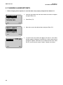
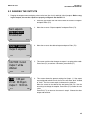
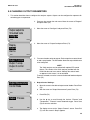
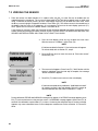
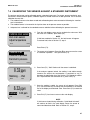
5.1 CHANGING ALARM SETPOINTS
1. Before changing alarm setpoints, be sure that alarms are properly configured. See Section 5.6.
2. Press any key to enter the main menu. Move the cursor to "Program"
and press Enter (F4).
Alarm setpoints
Output setpoints
Simulate tests
Exit
3. Press Enter (F4).
Enter
4. Move the cursor to the desired alarm and press Enter (F4).
Alarm 1 setpoint
Alarm 2 setpoint
Alarm 3 setpoint
Exit
Enter
Alarm Low : 0.000 ppm
Exit
24
Edit
5. A screen like the one shown will appear. The alarm is a low alarm
and the setpoint is 0.00 ppm. Press Edit (F4). Use the arrow keys to
change the setpoint. Press Save (F4) to store the new value. Press
Exit (F1) to return to the screen in step 4. Choose a new alarm.
MODEL DO-03/04
SECTION 5.0
SOFTWARE CONFIGURATION
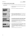
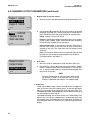
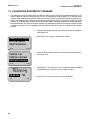
5.2 RANGING THE OUTPUTS
1. Ranging the outputs means assigning values to the low (0 or 4 mA) and high (20 mA) outputs. Before ranging the outputs, be sure the outputs are properly configured. See Section 5.5.
2. Press any key to enter the main menu. Move the cursor to "Program"
and press Enter (F4).
3. Move the cursor to "Output setpoints" and press Enter (F4).
Alarm setpoints
Output setpoints
Simulated test
Exit
Enter
Output 1 setpoints
Output 2 setpoints
Exit
4. Move the cursor to the desired output and press Enter (F4).
Enter
CAUTION: Current
Output 1 will be
affected.
Abort
5. This screen confirms that changes to output 1 are going to be made.
Press Cont (F3) to continue. Otherwise, press Abort (F1).
Cont
4 mA : 0.00 ppm
20 mA: 20.00 ppm
Output 1: 12.00 mA
Exit
Edit
6. This screen shows the present settings for Output 1. If the output
was configured to be 0-20 mA, the first line will show "0mA" instead
of "4mA". The live current output is shown on the third line.
Move the cursor to the desired line and press Edit (F4). Use the
arrow keys to change the setpoint. Press Save (F4) to store the new
value.
Press Exit (F1) to return to the screen in step 4. Choose the other
output and continue.
25
MODEL DO-03/04
SECTION 5.0
SOFTWARE CONFIGURATION
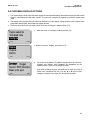
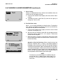
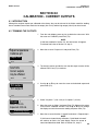
5.3 TESTING OUTPUTS AND ALARMS
1. For testing purposes, the analyzer can be programmed to generate simulated outputs and to activate and
deactivate alarms.
2. Press any key to enter the main menu. Move the cursor to "Program"
and press Enter (F4).
3. Move the cursor to "Simulated tests" and press Enter (F4).
Output setpoints
Simulated tests
Configure
Exit
Enter
4. Move the cursor to the desired output or alarm. Both outputs and all
four alarms can be tested. Press Enter (F4).
Test output 1
Test output 2
Test alarm 1
Exit
A screen will appear warning that the output or alarm will change.
Press Cont (F3) to continue. Press Abort (F1) to cancel the simulation.
Enter
Test output 1: 10.00 mA
The simulated current will be generated for 10 minutes, then the output returns to normal operation. To change the timeout to a different
value see Section 5.4.
Simulating output1
Exit
5. This screen appears when an output is being simulated. To change
the simulation current, press Edit (F4). Use the arrow keys to change
the current to the desired value. Press Test (F4), then Esc (F3).
Edit
To end the simulation at any time, press Exit (F1).
Test alarm 1: Open
6. This screen appears when an alarm is being simulated. To change
the state of the relay, press Edit (F4). Use the or keys to change
from open to closed. Press Test (F4), then Esc (F3).
Simulating alarm1
The alarm will be simulated for 10 minutes, then the alarm returns to
normal operation. To change the timeout to a different value, see
Section 5.4.
Exit
Edit
To end the simulation at any time, press Exit (F1).
26
MODEL DO-03/04
SECTION 5.0
SOFTWARE CONFIGURATION
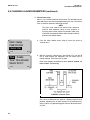
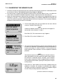
5.4 CHOOSING DISPLAY OPTIONS
1. The 54eA analyzer can be used with other oxygen sensors manufactured by Rosemount Analytical as well as with
chlorine, monochloramine, and ozone sensors. The user must configure the analyzer to match the sensor being
used.
2. The display menu also lets the user customize the third line in the display, change timeout values, choose a language other than English, and change the display contrast.
3. Press any key to enter the main menu. Move the cursor to "Program" and press Enter (F4).
4. Move the cursor to "Configure" and press Enter (F4).
Output setpoints
Simulated tests
Configure
Exit
Enter
5. With the cursor on "Display", press Enter (F4).
Display
Outputs
Alarms
Exit
Enter
Measure : Oxygen
Sensor: RMT Standard
Meas units: ppm
Exit
Edit
6. The screen at left appears. The default settings shown for “Measure”
(Oxygen) and “Sensor” (RMT Standard) are appropriate for the
499ADO sensor. There are no changes to make.
If you wish to change the units, use the key to move the cursor to
"Meas units" and press Edit (F4). Use the or keys to scroll
through the choices. Press Save (F4) to store the selection.
27
MODEL DO-03/04
SECTION 5.0
SOFTWARE CONFIGURATION
5.4 CHOOSING DISPLAY OPTIONS (CONTINUED)
7. Set the remainder of the display parameters. Use the and keys
to choose the desired parameter. Then press Edit (F4). Use the key to move the cursor to the desired selection. Press Save (F4) to
store.
Temp units: °C
Output 1: mA
Output 2: mA
Exit
Edit
Language: English
Display left: I
Display right: Out 2
Exit
Edit
Display contrast: 40
Timeout: On
Timeout value: 10 min
Exit
28
Edit
Temp units
°C or °F
Output 1
mA or % of full scale
Output 2
mA or % of full scale
Language
English, Français, Español, Deutsch, Italiano
Display left
sensor current (I), alarm 1 setpoint (no units),
alarm 3 setpoint (no units), or blank
Display right
sensor current (I), alarm 2 setpoint (no units),
alarm 3 setpoint (no units), output 2, or blank
Display Contrast
00 (lightest)-99 (darkest); the display contrast
changes as the number changes
Timeout
Timeout value
Timeout returns the display from any other screen
to the main display if no key is pressed before the
timeout value is exceeded.
Polling address
Identifies analyzer in multi-drop HART applications.
SECURITY CAUTION
The analyzer uses the timeout value to activate security. Once
the analyzer is unlocked by entering a security code, security will
not re-activate until a display timeout occurs. If timeout has been
turned off, security will never reactivate.
MODEL DO-03/04
SECTION 5.0
SOFTWARE CONFIGURATION
5.5 CHANGING OUTPUT PARAMETERS
1. This section describes how to configure the analyzer outputs. Outputs can be configured to represent dissolved oxygen or temperature.
2. Press any key to enter the main menu. Move the cursor to "Program"
and press Enter (F4).
3. Move the cursor to "Configure" and press Enter (F4).
Output setpoints
Simulated tests
Configure
Exit
Enter
4. Move the cursor to "Outputs" and press Enter (F4).
Display
Outputs
Alarms
Exit
Enter
5. Five menu headers relate to outputs. Each output has a control header and a setup header. The fifth header allows the output hold feature
to be configured.
Output 1 control
Output 1 setup
Output 2 control
Exit
NOTE
The 54eA analyzer can be ordered with optional PID control
feature. The version of the 54eA analyzer provided with the
DO-03/04 does not have control. Although the control header appears in this screen, it is not activated.
Enter
To access a header, move the cursor to the desired header and press
Enter (F4).
Output Measurement
Control Mode
6. Output Control Settings:
a. Move the cursor to the desired output control header. Press Enter
(F4).
b. With the cursor on "Output Measurement" press Enter (F4).
Exit
Enter
c.
Output : Process
Exit
Press Edit (F4).
d. Use the key to scroll through the choices: "Process" and
"Temperature". "Process" means dissolved oxygen. Press Save
(F4) to store the selection.
Edit
e. The display returns to the “Output: Process” screen. Press Exit
(F1) until the screen in Step 5 appears.
29
MODEL DO-03/04
SECTION 5.0
SOFTWARE CONFIGURATION
5.5 CHANGING OUTPUT PARAMETERS (continued)
7. Output setup for normal outputs:
Output 1 Control
Output 1 Setup
Output 2 Control
Exit
a. Move the cursor to the desired output setup and press Enter (F4).
Enter
b. Use the and arrow keys to move the cursor to the desired
parameter. Press Edit (F4). Use the arrow keys to change the setting to the desired value and press Save(F4) to store the value.
Range : 4-20 mA
Dampen: 0 sec
Hold: Last Value
Exit
Range: Choose 4-20 mA or 0-20 mA.
Edit
Dampen: Dampening averages the output current, thus smoothing out a noisy reading. Higher values provide more smoothing
but increase the response time of the output.
Hold and Fixed Hold: If the analyzer is placed in hold, the outputs will either remain at the last value or go to a fixed value
selected by the user. The fixed value must be between 0 and
22.00 mA.
Fault: If the analyzer detects a fault, the output will signal the fault
by going to a user-selected current between 0 and 22.00 mA.
For allowed values, see Table 5-1.
Output 2 control
Output 2 setup
Hold feature setup
Exit
8. Hold setup.
a. Move the cursor to "Hold feature setup" and press Enter (F4).
Enter
b. Press Edit (F4). Use the to scroll through the choices: "Disable
feature", "Enable feature", and "20 min timeout". If "20 min timeout" is selected, hold mode will automatically disengage after
being on for 20 minutes.
NOTE
Selecting "Enable hold" or "20-min timeout" does not put
the analyzer in hold. It only allows the user to put the
analyzer in hold when the analyzer is in calibrate mode.
9. Using hold.
If hold was enabled in step 8 above, the hold screen will appear as
soon as the user enters the Calibrate menu. To activate Hold, press
Edit (F4). Use the key to change Off to On and press Save (F4).
"Hold Mode Activated" will be displayed. Outputs and relays will go to
the values programmed in step 7b.
"Hold Mode Activated" will continue to flash in the main display even
after the user has left the Calibrate menu. To deactivate hold, enter
the Calibrate menu and press Edit (F4). Use the key to change On
to Off and press Save (F4). Press Exit (F1) twice to return to the main
display.
30
MODEL DO-03/04
SECTION 5.0
SOFTWARE CONFIGURATION
5.6 CHANGING ALARM PARAMETERS
1. This section describes how to configure the analyzer alarms. Alarms 1, 2, and 3 can be assigned to dissolved
oxygen or temperature. In addition, alarm 1, 2, or 3 can be configured as a feed limit timer or as an interval
timer (see steps 10 and 11). Alarm 4 is always a fault alarm.
2. Press any key to enter the main menu. Move the cursor to "Program"
and press Enter (F4).
3. Move the cursor to "Configure" and press Enter (F4).
Output setpoints
Simulated tests
Configure
Exit
Enter
4. Move the cursor to "Alarms" and press Enter (F4).
Outputs
Alarms
pH
Exit
Enter
5. Nine menu headers relate to alarms. Alarms 1, 2 and 3, each have a
control header and a setup header. Alarm 4 has only a setup header.
The eighth menu header is for configuring the feed limit timer, and the
ninth menu header is for configuring the interval timer.
Alarm 1 control
Alarm 1 setup
Alarm 2 control
Exit
NOTE
Enter
The 54eA analyzer can be ordered with optional TPC control
feature. The version of the 54eA analyzer provided with the
DO-03/04 does not have control. Although the control header appears in this screen, it is not activated.
To access a header, move the cursor to the desired header and press
Enter (F4).
6. Alarm Control Settings:
Activation method
Control mode
a. Move the cursor to the desired output control header. Press Enter
(F4).
b. With the cursor on "Activation method" press Enter (F4).
Exit
Enter
31
MODEL DO-03/04
SECTION 5.0
SOFTWARE CONFIGURATION
5.6 CHANGING ALARM PARAMETERS (continued)
c.
Activate : Process
Exit
Edit
a. Move the cursor to the desired alarm setup and press Enter (F4).
Enter
Alarm : Low
Setpoint: 0.000 ppm
Hysteresis: 0.000 ppm
Exit
Edit
FIGURE 5-2. Low Alarm
32
d. The display returns to the "Activate: Process" screen. Press Exit
(F1) until the screen in Step 5 appears.
8. Alarm setup for normal alarms:
Alarm 1 control
Alarm 1 setup
Alarm 2 control
Exit
To change the activation method, press Edit (F4). Use the key
to scroll through the choices, "Process" or "Temperature".
"Process" means dissolved oxygen. Press Save (F4) to store the
selection.
b. Use the and keys to move the cursor to the desired parameter. Press Edit (F4). Use the arrow keys to change the setting to
the desired value and press Save (F4) to store the value. See the
Figures 5-2 and 5-3 for an explanation of terms: low alarm, high
alarm, hysteresis, and delay. See Table 5-1 for allowed values
and limits.
Relay default determines how the relay will operate if there is a
fault or the analyzer is in hold. Alarms can be forced on (Close),
off (Open), or remain unchanged (None).
FIGURE 5-3. High Alarm
MODEL DO-03/04
SECTION 5.0
SOFTWARE CONFIGURATION
5.6 CHANGING ALARM PARAMETERS (continued)
9. Alarm 4 setup:
Alarm : Fault
Alarm 4 is a dedicated fault alarm. When a fault condition exists, the
red LED on the front display will light.
a. From the menu header screen (step 6) move the cursor to "Alarm
4 setup."
Exit
Edit
b. To disable the alarm, press Edit (F4) and use the key to
change the "Fault" to "Off"
10. Feed limit timer setup:
Alarm 1, 2, or 3 can be configured as a feed limit timer. The feed limit
timer prevents overfeeding of treatment chemicals by automatically
turning off the relay after a timeout period.
a. From the menu header screen (step 6) move the cursor to "Feed
limit timer." Press Enter (F4).
b. With the cursor on "Feed limit" press Edit. Use the key to scroll
through the choices: disable, AL 1, AL 2, and AL 3. Press Save
(F4) to store the selection.
Feed limit : Disable
Timeout: 3600 sec
Exit
c.
Move the cursor to "Timeout". Press Edit (F4) and use the arrow
keys to change the timeout to the desired value. Press Save (F4)
to store the setting.
Edit
1.000 ppm
26.2°C
12.0mA
Feed limit alarm 1
Operation of the feed limit timer. When a feed limit alarm has
timed out, "Feed limit alarm 1" (if alarm 1 was chosen) appears in
the display. At the same time the red FAIL LED will light and alarm
4 will close (if not turned off), and the selected feed limit relay (alarm
1) will open (de-energize). All other alarms and current outputs will
remain unchanged. The relays remain in the state described until
the Ack (F2) key is pressed, at which time the analyzer returns to
normal operation and the feed limit clock starts again.
NOTE
Pressing Ack (F2) acknowledges all conditions that turn
on the red LED. If another event occurs after F2 is
pressed, F2 must be pressed again to acknowledge the
new event.
33
MODEL DO-03/04
SECTION 5.0
SOFTWARE CONFIGURATION
5.6 CHANGING ALARM PARAMETERS (continued)
11. Interval timer setup:
Alarm 1, 2, or 3 can be used as an interval timer. The selected relay will
open and close at time intervals programmed by the user. The interval
timer is useful for automatic cleaning of sensors.
NOTE
The alarm relay used for the interval timer cannot be
used for other purposes. When a timer sequence is
occurring, both current outputs are placed in hold (even
if hold was not enabled) and the other two alarms will be
placed in their default states.
a. From the menu header screen (step 6) move the cursor to
"Interval timer."
Alarm 4 setup
Feed limit timer
Interval timer
Exit
Enter
Timer : Disable
Timer: Time activated
Interval: 24.0 hr
Exit
b. With the cursor on "Interval timer", press Enter (F4). Use the key to scroll through the selections. Use the arrow keys to
change settings. Press Save (F4) to store.
Refer to the diagram for definition of terms: interval, repeats, on
time, off time, and recovery.
Edit
FIGURE 5-4. Interval Timer
The user must determine the optimum cleaning frequency and
duration. Operating the air blast cleaner for 60 seconds every
eight (8) hours is a good starting point. Allow a 90-second recovery time.
34
MODEL DO-03/04
SECTION 5.0
SOFTWARE CONFIGURATION
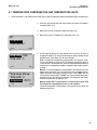
5.7 TEMPERATURE COMPENSATION AND TEMPERATURE UNITS
1. Refer to Section 6.1 for a discussion of the ways in which temperature affects dissolved oxygen measurement.
2. Press any key to enter the main menu. Move the cursor to "Program"
and press Enter (F4).
3. Move the cursor to "Configure" and press Enter (F4).
4. Move the cursor to "Temperature" and press Enter (F4).
pH
Temperature
Noise rejection
Exit
Enter
5. Use the and keys to move through the list of items. To make a
change press Edit (F4). Use the arrow keys to change settings to the
desired value. Press Save (F4) to store changes.
Temp comp : Auto
Temp units: °C
Exit
Edit
Temp comp: Manual
Temp units: °C
Temperature : 25.0°C
Exit
Edit
Auto: In automatic temperature compensation, the analyzer measures the temperature using an RTD (resistance temperature device)
in the sensor. The analyzer then uses the measured temperature to
calculate the membrane permeability correction and oxygen solubility factor.
Manual: In manual temperature compensation, the analyzer uses the
temperature entered by the user to calculate the membrane permeability correction and oxygen solubility factor. It does NOT use the
actual process temperature. Do NOT use manual temperature compensation unless the difference between the calibration and measurement temperatures is less than 2°C.
Manual temperature compensation is useful if the sensor RTD
has failed and a replacement sensor is not available.
If Manual temperature compensation is selected, be sure to enter the
desired temperature.
35
MODEL DO-03/04
SECTION 5.0
SOFTWARE CONFIGURATION
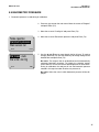
5.8 NOISE REDUCTION
1. For maximum noise reduction the frequency of the ac power must be entered into the analyzer.
2. Press any key to enter the main menu. Move the cursor to "Program"
and press Enter (F4).
3. Move the cursor to "Configure" and press Enter (F4).
4. Move the cursor to "Noise rejection" and press Enter (F4).
Temperature
Noise rejection
Main sensor cal
Exit
Enter
Noise rejection : 60 Hz
Exit
36
Edit
5. To change the frequency setting, press Edit (F4). Use the key to
toggle between 50 and 60 Hz. Press Save (F4) to store the change.
MODEL DO-03/04
SECTION 5.0
SOFTWARE CONFIGURATION
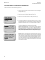
5.9 BAROMETRIC PRESSURE
1. Barometric pressure is used during air calibration.
2. Press any key to enter the main menu. Move the cursor to "Program"
and press Enter (F4).
3. Move the cursor to "Configure" and press Enter (F4).
Noise rejection
Barometric pressure
Main sensor cal
Exit
Enter
5. Use the and keys to move through the list of items. To make a
change, press Edit (F4). Use the arrow keys to change settings to the
desired value and press Save (F4).
Bar meas : Auto
Bar units: mm Hg
Exit
4. Move the cursor to "Barometric pressure" and press Enter (F4).
Edit
Bar meas: The analyzer has an on-board sensor that automatically
measures barometric pressure. To bypass the pressure sensor,
select "Manual'. Be sure to enter the desired pressure in the third line.
During air calibration, the analyzer will use the barometric pressure
entered in this step no matter what the true pressure is.
Bar units: Select the units in which barometric pressure will be displayed.
37
MODEL DO-03/04
SECTION 5.0
SOFTWARE CONFIGURATION
5.10 MAIN SENSOR CALIBRATION PARAMETERS
1. Main sensor refers to the dissolved oxygen sensor.
2. Press any key to enter the main menu. Move the cursor to "Program"
and press Enter (F4).
3. Move the cursor to "Configure" and press Enter (F4).
4. Move the cursor to "Main sensor cal" and press Enter (F4).
Noise rejection
Main sensor cal
Security
Exit
Enter
5. Use the and keys to move through the list of items. To make a
change press Edit (F4). Use the arrow keys to change settings to the
desired value and press Save (F4). For allowed ranges, see Table 5-1.
The choices depend on the measurement being made.
Stabilize : 0.050 ppm
Stabilize time: 10 sec
Exit
Edit
Stabilize: 0.050 ppm
Stabilize time: 10 sec
Salinity : 0.0 o/oo
Exit
38
Stabilize and Stabilize time: For the analyzer to accept calibration
data, the concentration must remain within a specified range for a
specified period of time. The default values are 0.05 ppm and 10 seconds. Using a small stabilize value and a long stabilize time is the
best protection against calibration while a reading is still changing.
Edit
Salinity: Salinity is used with oxygen measurements only. The solubility of oxygen in water depends on the concentration of dissolved
salts in the water. Increasing the concentration decreases the solubility. If the salt concentration is greater than about 1000 ppm, the accuracy of the measurement can be improved by applying a salinity correction. Enter the salinity as parts per thousand (o/oo). One percent
is ten parts per thousand.
MODEL DO-03/04
SECTION 5.0
SOFTWARE CONFIGURATION
5.11 SECURITY
1.
The analyzer can be programmed to require a password for access to menus. There are three levels:
Level 1: A level 1 user can
1. Zero and calibrate the oxygen sensor
2. Calibrate the barometric pressure sensor
3. Change temperature compensation from automatic to manual and enter a manual compensation temperature
4. View diagnostic variables.
Level 2: A level 2 user can
1. Do everything a level 1 user can do
2. Change alarm setpoints
3. Rerange the 4-20 mA outputs
4. Manually test both outputs and all four alarm relays.
Level 3: A level 3 user has access to every menu item. Only a level 3 user can change passwords.
A person with no password can only view the main display.
Noise rejection
Main sensor cal
Security
Exit
Press any key to enter the main menu. Move the cursor to "Program" and
press Enter (F4).
3.
Move the cursor to "Configure" and press Enter (F4).
4.
Move the cursor to "Security" and press Enter (F4).
5.
Use the and keys to move through the list of items. To enter a password,
press Edit (F4). Use the arrow keys to enter a three-digit password. Press
Save (F4) to store the value.
Enter
Lock all : 0
Lock program: 0
Lock config: 0
Exit
2.
Lock all: Until the user enters the "lock all" password, all he can do is view
the main display. Entering the "lock all" password allows the user access to
all Level 1 functions.
Edit
Lock program: Entering the "lock program" password allows the user
access to all Level 2 functions.
Lock config: Entering the "lock config" password allows the user access to
all Level 3 functions.
The analyzer will accept a higher level security code at a lower level security gate. For example, the analyzer will accept a level 2 password at a level 1
gate.
NOTES:
a.
A code of 000 disables security for that level.
b.
The security feature will not activate until after the timeout period has
passed with no key presses.
c.
A hold condition will indefinitely prolong the timeout period.
d.
Security will activate immediately if power is removed and then restored.
e.
To recall a forgotten code, press and hold F4 for five seconds when the
security screen appears. The code for that level will appear.
39
MODEL DO-03/04
SECTION 5.0
SOFTWARE CONFIGURATION
5.12 ANALYZER MODE PRIORITY
The Model 54eA analyzer can function in different modes
depending on how it is configured, what process conditions exist, and actions an operator may have made. To
reconcile these possible modes, there is a set priority that
determines exactly what will happen to the two (2) current
outputs and the four (4) alarm relays in the event of multiple modes occurring at the same time. See Table 5-2
below.
Priority is in the following order (from lowest to highest):
normal, fault, timer, hold, feed limit, test. Each output or
relay acts as if it is only in the state of highest priority.
NOTE
Some of these features may not be in use in
the analyzer.
TABLE 5-2. Analyzer Mode Priority Chart
Condition
1
Priority
Current
Output 1
Current
Output 2
Alarm
Relay 1
Alarm
Relay 2
Alarm
Relay 3
Alarm
Relay 4
Normal
1
Normal
Normal
Normal
Normal
Normal
Open
Fault
2
Default
Default
Default
Default
Default
Closed
Interval Timer
3
Hold
Hold
Default/
Normal1
Default/
Normal1
Default/
Normal1
Prior
Hold Mode
4
Hold
Hold
Default
Default
Default
Prior
Feed Limit
5
Normal
Normal
Open1
Open1
Open1
Closed
Simulate tests
6
Test1
Test1
Test1
Test1
Test1
Test1
Indicates the state IF that item has been configured or selected (i.e. if it is an interval timer or a feed limit
timer or it is the one being tested). Unconfigured or unselected items are not affected by that mode.
Condition Definitions:
1. Normal refers to conditions when no other mode is present.
2. Fault means the instrument has diagnosed a fault condition. A fault message is displayed and the red LED
is on.
3. Interval Timer means the timer sequence is occurring.
4. Hold Mode occurs when hold is activated by the operator (i.e. during calibration).
5. Feed Limit occurs when a feed limit timer has reached its limit and is turned off after being on for too long.
6. Simulate tests are described in Section 5.4.
Action Definitions:
1. Normal is determined by process conditions or how the item has been configured (Section 5.6)
2. Open is a deenergized alarm relay (alarm off).
3. Default is the setting configured for each item if there is a fault. (Section 5.6)
4. Closed is an energized alarm relay (alarm on).
5. Hold is the setting for the current output configured in Section 5.5 (fixed mA value or the last normal value).
6. Prior is the state the alarm had before that mode occurred.
7. Test is the value input by the operator (mA for current, on or off for a relay).
40
MODEL DO-03/04
SECTION 6.0
CALIBRATION - TEMPERATURE
SECTION 6.0
CALIBRATION - TEMPERATURE
6.1 INTRODUCTION
The Model 499ADO sensor is a membrane-covered amperometric sensor. As the sensor operates, oxygen diffuses through the membrane and is consumed at an electrode immediately behind the membrane. The reaction produces a current that depends on the rate at which oxygen diffuses through the membrane. The diffusion rate, in turn,
depends on the concentration of oxygen and how easily it passes through the membrane (the membrane permeability). Because the membrane permeability is a function of temperature, the sensor current will change if the temperature changes. To correct for changes in sensor current caused by temperature, the analyzer automatically
applies a membrane permeability correction that converts the sensor current to the value at 25°C. The change is
about 3%/°C at 25°C, so a 1°C error in temperature produces about a 3% error in the reading.
Temperature plays an additional role in oxygen measurements. Oxygen sensors are calibrated by exposing them
to water-saturated air, which, from the point of view of the sensor, is equivalent to water saturated with atmospheric oxygen (see Section 7.0 for more information). During calibration, the analyzer calculates the solubility of atmospheric oxygen in water using the following steps. First, the analyzer measures the temperature. From the temperature, the analyzer calculates the vapor pressure of water and, using the barometric pressure, calculates the partial pressure of atmospheric oxygen. Once the analyzer knows the partial pressure, it calculates the equilibrium
solubility of oxygen in water using a temperature-dependent factor called the Bunsen coefficient. Overall, a 1°C
error in the temperature measurement produces about a 2% error in the solubility calculated during calibration and
about the same error in subsequent measurements.
Without calibration the accuracy of the temperature measurement is about ±0.4°C. Calibrate the controller if
1. ±0.4°C accuracy is not acceptable
2. the temperature measurement is suspected of being in error. Calibrate temperature by making the controller
reading match the temperature measured with a standard thermometer.
41
MODEL DO-03/04
SECTION 6.0
CALIBRATION - TEMPERATURE
6.2 TEMPERATURE CALIBRATION
Place the sensor and a standard thermometer in the process liquid.
1. Check the analyzer temperature reading (main display) to make sure the sensor has stabilized. Compare the
analyzer temperature with the standard thermometer. The readings should differ by at most 1°C. If the readings differ by a greater amount, refer to Section 15.3. Go to the next step if the reading requires adjustment.
2. From the main display, press any key. With the cursor on “Calibrate,”
press Enter (F4).
NOTE
If Hold was enabled in Section 5.5, the hold screen will appear.
To activate hold, refer to Section 5.5, step 9.
Zero main sensor
Adjust temperature
Output trim
Exit
3. Press the key twice to move the cursor to “Adjust temperature,”
then press Enter (F4).
Enter
4. Press Edit (F4) to adjust the temperature. The screen below will then
appear. Using the arrow keys, enter the correct temperature and
press Save (F4). The controller will enter the value in memory. To
abort the change, press Esc (F3). Press Exit (F1) three times for the
main display.
25.1 °C
Adjust temp : 25.1 °C
Exit
Edit
If Hold was activated during calibration, “Hold Mode Activated”
will continue to flash in the main display. Return the sensor to
normal and deactivate Hold. Refer to Section 5.5, step 9.
25.1 °C
Adjust temp : + 025.1 °C
Esc
42
NOTE
Save
MODEL DO-03/04
SECTION 7.0
CALIBRATION - DISSOLVED OXYGEN
SECTION 7.0
CALIBRATION - DISSOLVED OXYGEN
7.1 INTRODUCTION
As Figure 7-1 shows, oxygen sensors generate a current directly proportional to the concentration of dissolved
oxygen in the sample. Calibrating the sensor requires exposing it to a solution containing no oxygen (zero standard) and to a solution containing a known amount of oxygen (full-scale standard).
The zero standard is necessary because oxygen sensors, even when no oxygen is present in the sample, generate a small current called the residual current. The analyzer compensates for the residual current by subtracting it
from the measured current before converting the result to a dissolved oxygen value. New sensors require zeroing
before being placed in service, and sensors should be zeroed whenever the electrolyte solution is replaced. The
recommended zero standard is 5% sodium sulfite in water, although oxygen-free nitrogen can also be used.
The purpose of the full-scale standard is to establish the slope of the calibration curve. Because the solubility of
atmospheric oxygen in water as a function of temperature and barometric pressure is well known, the natural
choice for a full-scale standard is air-saturated water. However, air-saturated water is difficult to prepare and use,
so the universal practice is to use air for calibration. From the point of view of the oxygen sensor, air and air-saturated water are identical. The equivalence comes about because the sensor really measures the chemical potential of oxygen. Chemical potential is the force that causes oxygen molecules to diffuse from the sample into the
sensor where they can be measured. It is also the force that causes oxygen molecules in air to dissolve in water
and to continue to dissolve until the water is saturated with oxygen. Once the water is saturated, the chemical
potential of oxygen in the two phases (air and water) is the same.
Oxygen sensors generate a current directly proportional to the rate at which oxygen molecules diffuse through a
membrane stretched over the end of the sensor. The diffusion rate depends on the difference in chemical potential between oxygen in the sensor and oxygen in the sample. An electrochemical reaction, which destroys any oxygen molecules entering the sensor, keeps the concentration (and the chemical potential) of oxygen inside the sensor equal to zero. Therefore, the chemical potential of oxygen in the sample alone determines the diffusion rate
and the sensor current.
When the sensor is calibrated, the chemical potential of oxygen in the standard determines the sensor current.
Whether the sensor is calibrated in air or air-saturated water is immaterial. The chemical potential of oxygen is the
same in either phase. Normally, to make the calculation of solubility in common units (like ppm DO) simpler, it is
convenient to use water-saturated air for calibration.
Automatic air calibration is standard. The user simply exposes the sensor to water-saturated air. The analyzer
monitors the sensor current. When the current is stable, the analyzer stores the current and measures the barometric pressure and temperature. The temperature element is part of the dissolved oxygen sensor. The pressure
sensor is inside the analyzer. From the temperature, the analyzer calculates the saturation vapor pressure of water.
Next, it calculates the pressure of dry air by subtracting the vapor pressure from the barometric pressure. Using
the fact that dry air always contains 20.95% oxygen, the
analyzer calculates the partial pressure of oxygen. Once
the analyzer knows the partial pressure of oxygen, it uses
the Bunsen coefficient to calculate the equilibrium solubility of atmospheric oxygen in water at the prevailing temperature. At 25°C and 760 mm Hg, the equilibrium solubility is 8.24 ppm.
Often it is too difficult or messy to remove the sensor from
the process liquid for calibration. In this case, the sensor
can be calibrated against a measurement made with a
portable laboratory instrument. The laboratory instrument
typically uses a membrane-covered amperometric sensor
that has been calibrated against water-saturated air.
FIGURE 7-1. Sensor Current as a Function of
Dissolved Oxygen Concentration
43
MODEL DO-03/04
SECTION 7.0
CALIBRATION - DISSOLVED OXYGEN
7.2 ZEROING THE SENSOR
1. Place the sensor in a fresh solution of 5% sodium sulfite (Na2SO3) in water. Be sure air bubbles are not
trapped against the membrane. The current will drop rapidly at first and then gradually reach a stable zero
value. To monitor the sensor current, go to the main display. Press any key to obtain the main menu. Press
the key once to highlight “Diagnostic variables.” Press Enter (F4). The sensor current is the second item in
the display. Note the units: nA is nanoamps, μA is microamps. To return to the main display, press exit (F1)
twice. Typical zero current for a 499ADO sensor is less than 50 nA.
A new sensor or a sensor in which the electrolyte solution has been replaced may require several hours (occasionally as long as overnight) to reach a minimum current. DO NOT START THE ZERO ROUTINE UNTIL THE
SENSOR HAS BEEN IN ZERO SOLUTION FOR AT LEAST TWO HOURS.
2. From the main display, press any key to obtain the main menu.
With the cursor on “Calibrate,” press Enter (F4).
NOTE
If Hold was enabled in Section 5.5, the hold screen will appear.
To activate hold, refer to Section 5.5, step 9.
Calibrate main sensor
Zero main sensor
Adjust temperature
Exit
Enter
0.0 ppm
Sensor must be in zero
solution
Abort
3. Press the key once to move the cursor to “Zero main sensor.”
Press Enter (F4).
4. The screen at left appears. Press Cont (F3). “Wait” flashes until the
sensor is stabilized. Once the zero step is complete, the message
“Sensor zero done” appears.
5. Press Exit (F1) three times to return to the main display.
Cont
NOTE
If Hold was activated during calibration, “Hold Mode Activated”
will continue to flash in the main display. Return the sensor to
normal and deactivate Hold. Refer to Section 5.5, step 9.
NOTE
During calibration, ERROR and WARNING messages may appear. If an ERROR message appears, press
Exit (F1) to leave and return to the previous screen. If a WARNING message appears, press Cont (F3) to
continue the calibration or press Abort (F1) to leave. Continuing the calibration after a warning message
appears may cause substantial errors in the subsequent measurement. Refer to Section 15.4 for assistance.
44
MODEL DO-03/04
SECTION 7.0
CALIBRATION - DISSOLVED OXYGEN
7.3 CALIBRATING THE SENSOR IN AIR
1. Remove the sensor from the process liquid. Use a soft tissue and a stream of water from a wash bottle to clean
the membrane. Blot dry. The membrane must be dry during air calibration.
2. Pour some water in a beaker and suspend the sensor with the membrane about 0.5 inch (1 cm) above the
water surface. To avoid drift caused by temperature changes, keep the sensor out of the direct sun.
3. Monitor the dissolved oxygen reading and the temperature. Once readings have stopped drifting, begin the
calibration. It may take 5 - 10 minutes for the sensor reading in air to stabilize. Stabilization time may be even
longer if the process temperature is appreciably different from the air temperature. For an accurate calibration,
temperature measured by the sensor must be stable.
Calibrate main sensor
Zero main sensor
Adjust temperature
Exit
4. From the main display, press any key to obtain the main menu. With the
cursor on “Calibrate,” press Enter (F4).
NOTE
If Hold was enabled in Section 5.5, the hold screen will appear. To
activate hold, refer to Section 5.5, step 9.
Enter
Press Enter (F4). The screen shown in step 5 appears.
Calibrate in air
Calibrate in process
Barometric pressure
Exit
Enter
Bar press : 760 mmHg
Temperature: 25.0°C
Press F3 to air cal
Abort
5. Press Enter (F4) to select “Calibrate in air.”
6. This screen shows the barometric pressure and temperature that will
be used for the calibration. If the barometric pressure or temperature is
incorrect, press Abort (F1). Refer to Section 7.5 for the pressure calibration procedure. Refer to Section 6.2 for the temperature calibration
procedure.
Cont
NOTE
The barometric pressure sensor is inside the controller enclosure.
When cable glands are in place and the front panel is tightly closed,
the enclosure is moderately airtight. Therefore, as the controller
heats or cools, the pressure of the air trapped inside the enclosure
may be different from ambient. Opening the front panel will equalize the pressure.
8.20 ppm
Stabilizing . . . Wait
Abort
Cont
7. Press Cont (F3). “Wait” flashes until the sensor is stabilized. Once air
calibration is complete, the message “Air calibration done” appears.
The display will show the equilibrium solubility of atmospheric oxygen
in water at the prevailing temperature and pressure.
procedure continued on next page . . .
45
MODEL DO-03/04
SECTION 7.0
CALIBRATION - DISSOLVED OXYGEN
8. Press Exit (F1) four times to return to the main display.
NOTE
If Hold was activated during calibration, “Hold Mode Activated” will
continue to flash in the main display. Return the sensor to normal
and deactivate Hold. Refer to Section 5.5, step 9.
9. During calibration, the analyzer stores the measured current and calculates the sensitivity. Sensitivity is the sensor current in nA divided by the
saturation concentration of oxygen in ppm. Typical sensitivity for a
499ADO sensor is 1,800 to 3,100 nA/ppm (15 - 25 μA in air).
To view the sensitivity from the main display, press any key to enter the
main menu. Press the key once. Then press Enter (F4) to display the
diagnostic variables. The sensitivity is the third line on the screen. Note
the units: nA is nanoamps, μA is microamps.
NOTE
During calibration, ERROR and WARNING messages may appear. If an ERROR message appears, press
Exit (F1) to leave and return to the previous screen. If a WARNING message appears, press Cont (F3) to
continue the calibration or press Abort (F1) to leave. Continuing the calibration after a warning message
appears may cause substantial errors in the subsequent measurement. Refer to Section 15.4 for assistance.
46
MODEL DO-03/04
SECTION 7.0
CALIBRATION - DISSOLVED OXYGEN
7.4 CALIBRATING THE SENSOR AGAINST A STANDARD INSTRUMENT
The analyzer and sensor can be calibrated against a standard instrument. For oxygen sensors installed in aeration basins in waste treatment plants, calibration against a second instrument is often preferred. For an accurate
calibration be sure that…
1. The standard instrument has been zeroed and calibrated against water-saturated air following the manufacturer's instructions.
2. The standard sensor is immersed in the liquid as close to the process sensor as possible.
3. Adequate time is allowed for the standard sensor to stabilize before calibrating the process instrument.
Calibrate main sensor
Zero main sensor
Adjust temperature
Exit
4. From the main display, press any key to obtain the main menu. With
the cursor on “Calibrate,” press Enter (F4).
NOTE
If Hold was enabled in Section 5.5, the hold screen will appear.
To activate hold, refer to Section 5.5, step 9.
Enter
Press Enter (F4).
Calibrate in air
Calibrate in process
Barometric pressure
Exit
Enter
6. Press Cont (F3). “Wait” flashes until the sensor is stabilized.
8.32 ppm
If the analyzer appears locked, the reading is not stable enough.
Increase the amount the concentration is permitted to vary or
decrease the stabilization time. See Section 5.10. Repeat the calibration. To proceed with the calibration as is, press Cont (F3).
Stabilizing . . . Wait
Abort
Cont
7. Once the reading is stable, the screen at left appears. Press Edit
(F4). Use the arrow keys to change the concentration in the second
line of the display to the desired value. Press Save (F4) to store the
value.
8.32 ppm
Calibrate : 8.32 ppm
Exit
5. The screen at left appears. Press the key once to move the cursor
to “Calibrate in process.” Then, press Enter (F4).
8. Press Exit (F1) four times to return to the main display.
Edit
NOTE
If Hold was activated during calibration, “Hold Mode Activated”
will continue to flash in the main display. Return the sensor to
normal and deactivate Hold. Refer to Section 5.5, step 9.
47
MODEL DO-03/04
SECTION 7.0
CALIBRATION - DISSOLVED OXYGEN
7.5 CALIBRATING BAROMETRIC PRESSURE
1. If the barometric pressure measured by the analyzer does not agree with the local barometric pressure, calibrate the pressure sensor. A pressure error of 3 mm Hg introduces an error of about 0.5% in the final measurement. When calibrating the pressure reading, be sure to use the actual barometric pressure. Weather forecasters and airports usually report barometric pressure corrected to sea level; they do not report the acutal
pressure. It is good practice to open the enclosure door before starting a barometric pressure calibration.
When gland fittings are used, the analyzer enclosure is moderately airtight. As the analyzer enclosure heats
or cools, the pressure of the air trapped inside the enclosure may be as much as 5% different from ambient
pressure.
2. From the main display, press any key. With the cursor on “Calibrate,”
press Enter (F4).
Calibrate main sensor
Zero main sensor
Adjust temperature
Exit
Enter
Calibrate in air
Calibrate in process
Barometric pressure
Exit
Standardize : 760
48
4. Press the key twice to move the cursor to “Barometric pressure.”
Press Enter (F4).
Enter
763 mm Hg
Exit
3. Press Enter (F4) to select “Calibrate main sensor.”
5. Press Edit (F4). Use the arrow keys to change the pressure reading
to the desired value. Press Save (F4) to store the value.
6. Press Exit (F1) four times to return to the main display.
Edit
MODEL DO-03/04
SECTION 8.0
CALIBRATION - CURRENT OUTPUTS
SECTION 8.0
CALIBRATION - CURRENT OUTPUTS
8.1 INTRODUCTION
Although the analyzer outputs are calibrated at the factory, they can be trimmed in the field to match the reading
from a standard current meter. Both the low output (0 or 4 mA) and the high output (20 mA) can be trimmed.
8.2 TRIMMING THE OUTPUTS
1. From the main display, press any key to obtain the main menu. With
the cursor on "Calibrate" press Enter (F4).
NOTE
If Hold was enabled in Section 5.6, the hold screen will appear.
To activate hold, refer to Section 5.6, step 11.
2. Move the cursor to "Output trim” and press Enter (F4).
Adjust temperature
Calibrate pH
Output trim
Exit
Enter
3. The warning screen reminds the user that the output currents will be
affected. Pres Cont (F3) to continue.
CAUTION:
Current outputs
may be affected
Abort
Cont
4. Use the or keys to move the cursor to the desired output and
press Enter (F4).
Trim output 1
Trim output 2
Exit
Enter
5. Select “Cal point 1” (0 or 4 mA) or “Cal point 2” (20 mA).
Cal point : 1
Meter: 4.00 mA
Expected: 4.00 mA
6. Move the cursor to “Meter” and press Enter (F4). Measure the output
current with a calibrated ammeter. Use the or keys to change
the display to match the ammeter reading and press Save (F4).
Simulating output1
Exit
Edit
7. Move the cursor to the other “Cal point” and select it. Repeat step 6.
NOTE
If Hold was activated during calibration, “Hold Mode Activated”
will continue to flash in the main display. Return the sensor to
normal and deactivate Hold. Refer to Section 5.6, step 11.
49
MODEL DO-03/04
SECTION 9.0
MAINTENANCE
SECTION 9.0
MAINTENANCE
9.1 ANALYZER (MODEL 54eA-01)
The Model 54eA-01 analyzer provided with the Model DO-03/04 system requires little routine maintenance.
Clean the analyzer enclosure and front panel by wiping with a clean soft cloth dampened with water. A mild detergent solution can also be used. Do not use solvents, like alcohol, that might cause a buildup of static charge.
Table 9-1 gives a list of replacement parts.
TABLE 9-1. Replacement Parts
PART NUMBER
23540-05
23848-00
23849-00
23969-02
23969-06
33281-00
33286-00
33293-00
9010377
9510048
DESCRIPTION
Enclosure, Front with Keyboard
Power Supply Circuit Board Shield
Half Shield, Power Supply
PCB, CPU and power supply, calibrated, 115/230 Vac
PCB, CPU and power supply, calibrated, 24 Vdc
Hinge Pin
Gasket, Front Panel
Enclosure, Rear
Back-lit Display, LCD Dot Matrix
Enclosure Conduit Plug, 1/2 inch
9.2 OXYGEN SENSOR (MODEL 499ADO-54)
9.2.1 General
The oxygen sensor requires little maintenance. Generally, the sensor needs attention when the response becomes sluggish or noisy or when readings drift following calibration.
9.2.2 Cleaning the membrane
Although the air blast cleaner does a good job of keeping the membrane clean, a thin film of slime can eventually accumulate on the membrane. Slime can be removed by rinsing the membrane with clean water. A soft cloth or
tissue can also be used to wipe the membrane.
9.2.3 Replacing electrolyte solution and membrane
To replace the membrane or fill solution, the sensor must first be removed from the air blast washer head assembly.
To remove the sensor from the air blast cleaner …
1. A pair of O-rings and a set screw hold the two parts of the sensor washer head assembly together. Remove
the set screw and pull on the bottom of the assembly until it is clear. The quick disconnect for the air hose
should be easily accessible.
2. Disconnect the air hose by pressing on the metal tab of the fitting and pulling the hose away from the base.
3. Unscrew the base from the sensor. DO NOT LOSE THE O-RING THAT SEALS THE SENSOR TO BOTTOM
ASSEMBLY.
50
MODEL DO-03/04
SECTION 9.0
MAINTENANCE
To reassemble the sensor and air blast cleaner…
1. Inspect the sensor O-ring. If it is cracked or cut, replace it. Clean the O-ring and slide it over the end of the
sensor until it rests against the lower edge of the bottom facing threads.
2. Clean and dry the bottom portion of the sensor washer assembly. Inspect the surface that the sensor O-ring
seals against to verify that it is clean and smooth. Inspect the dual O-rings to ensure that they are not cracked
or cut. If the O-rings appear to be damaged, replace them.
NOTE
The sensor O-ring and the two washer head O-rings are available in PN 24053-00.
3. Be sure the O-ring sealing surfaces in the upper portion of the sensor washer head assembly are clean and
smooth.
4. Reconnect the air hose.
5. Lubricate the O-rings with a small amount of grease. Push the bottom part of the sensor washer head
back into the upper portion of the assembly. Replace and tighten the set screw.
To replace the electrolyte solution and membrane...
1. Unscrew the membrane retainer and remove the membrane assembly
and O-ring. See Figure 9-1.
2. Hold the sensor over a container with the cathode pointing down.
CAUTION
Fill solution may cause
irritation. May be harmful if swallowed. Read
and follow manual.
3. Remove the fill plug and allow the electrolyte solution to drain out.
4. Inspect the cathode. If it is tarnished, clean it by gently rubbing in the direction of the existing scratches (do
not use a circular motion) with 400-600 grit silicon carbide finishing paper. Rinse the cathode thoroughly with
water.
5. Wrap the plug with several turns of pipe tape and set aside.
6. Prepare a new membrane. Hold the membrane assembly with the cup formed by the membrane and membrane holder pointing up. Fill the cup with electrolyte solution. Leave the membrane assembly filled with electrolyte solution and set it aside.
7. Hold the sensor at about a 45-degree angle with the cathode end pointing up. Add electrolyte solution through
the fill hole until the liquid overflows. Tap the sensor near the threads to release trapped air bubbles. Add more
electrolyte solution if necessary.
8. Place the fill plug in the electrolyte port and begin screwing it in. After several threads have engaged, rotate
the sensor so that the cathode is pointing up and continue tightening the fill plug. Do not overtighten.
9. Place a new O-ring in the groove around the cathode post. Cover the holes at the base of the cathode stem
with several drops of electrolyte solution.
10. Insert a small blunt probe, like a toothpick with the end cut off, through the pressure equalizing port. See
Figure 9-1.
NOTE
Do not use a sharp probe. It will puncture the bladder and destroy the sensor.
Gently press the probe against the bladder several times to force liquid through the holes at the base of the
cathode stem. Keep pressing the bladder until no air bubbles can be seen leaving the holes. Be sure the holes
remain covered with electrolyte solution.
11. Place a drop of electrolyte solution on the cathode, then place the membrane assembly over the cathode.
Screw the membrane retainer in place.
12. The sensor may require several hours operating at the polarizing voltage to equilibrate after the electrolyte
solution has been replenished.
NOTE
If the membrane and electrolyte solution were replaced, check the sensor performance
before reassembling the sensor and washer head assembly. To zero the sensor, refer to
Section 7.2. To perform an air calibration, refer to Section 7.3.
51
MODEL DO-03/04
SECTION 9.0
MAINTENANCE
FIGURE 9-1. Sensor Parts
SPARE PARTS
33523-00
Electrolyte Fill Plug
9550094
O-Ring, Viton 2-014
24057-00
Membrane Retainer (smooth cap)
23501-00
Dissolved Oxygen Membrane Assembly: includes one membrane assembly and one O-ring
23502-00
Dissolved Oxygen Membrane Kit: includes 3 membrane assemblies and 3 O-rings
9210264
#1 Dissolved Oxygen Sensor Fill Solution, 4 oz (120 mL)
9.3 AIR COMPRESSOR (PN 9380088 115Vac or PN 9380089 220 Vac)
The air compressor has no user-serviceable parts. It does not require lubrication. Fuse sizes are shown in the
table. The fuse is located below the T-shaped plastic cover next to the air compressor.
Power
52
Fuse
100-115 Vac
AGC-4, 4A, 250V
230 Vac
AGC-2, 2A, 250V
DANGER
Hazardous Voltage
Can cause severe injury or death.
Disconnect power before servicing.
MODEL DO-03/04
SECTION 9.0
MAINTENANCE
9.4 AIR BLAST SENSOR WASHER
The air blast sensor washer needs little routine maintenance. Replace the two large O-rings on the base of the
washer head and the sensor sealing O-ring if they become cut or dirty or if there is evidence of water leaking into
the washer head. The three O-rings are available as a kit (PN 24053-00).
See Figure 9-2 for replacement parts.
FIGURE 9-2. Replacement Parts
Location
Part Number
Description
1
24049-00
2
note
3
24054-00
O-ring kit, quantity 3 with barium lube
4
24055-00
Quick disconnect and check valve assembly
5
33866-00
Air hose, 25 ft, 1/4-inch ID
Sensor washer head
Screw, 1/4 x 20 x 0.375 SFH
Screw size is for information only. Screw cannot be purchased from Rosemount.
53
MODEL DO-03/04
SECTION 10.0
TROUBLESHOOTING
SECTION 10.0
TROUBLESHOOTING
10.1 OVERVIEW
The 54eA analyzer continuously monitors itself and the sensor for faults. When the analyzer detects a fault in the
oxygen sensor or in the instrument itself it displays a fault message. If alarm 4 was enabled, the red FAIL LED
will also light and relay 4 will activate. The outputs will go to 22.00 mA or to the value programmed in Section 5.5.
See Section 10.2 for an explanation of fault messages and suggested corrective actions.
The analyzer also displays error and warning messages if a calibration is seriously in error. Refer to the section
below for assistance. Each section also contains hints for correcting other measurement and calibration problems.
Measurement
Temperature
Dissolved oxygen
Section
10.3
10.4
For troubleshooting not related to measurement problems, see Section 10.5.
To view diagnostic variables, go to the main display and press any key. Move the cursor to “Diagnostic variables”
and press Enter (F4). Use the or key to move up or down the list.
10.2 TROUBLESHOOTING WHEN A FAULT MESSAGE IS SHOWING
54
Fault message
Explanation
See Section
High input current
input current exceeds 210 uA
10.2.1
Check sensor zero
sensor current was too high when sensor was zeroed
10.2.2
Temp error low
temperature less than -15°C
10.2.3
Temp error high
temperature greater than 130°C
10.2.3
Sense line open
RTD sense line is open
10.2.4
Failure factory
Failure eeprom
instrument needs factory calibration
write verify error has occurred
10.2.5
10.2.5
MODEL DO-03/04
SECTION 10.0
TROUBLESHOOTING
10.2.1 High input current
Excessive sensor current implies that the oxygen sensor is miswired or the sensor has failed. Verify that wiring is
correct, including connections through a junction box. See Section 3.3. If wiring is correct, try replacing the sensor.
105.2.2 Check sensor zero
The sensor current was extremely high when the sensor was zeroed. Typical zero current for an oxygen sensor is
less than 50 nA. Zeroing the sensor before the zero current has reached a stable minimum value will lead to low
results. Allow adequate time, possibly as long as overnight, for the sensor to stabilize before starting the zero routine.
10.2.3 Temperature error low or high
Temperature error usually means the RTD is open or shorted or there is an open or short in the connecting wiring.
First, verify all wiring connections, including wiring connections in the junction box if one is being used. Next, disconnect the RTD IN, SENSE, and RETURN leads at the analyzer. Be sure to note the color of the wire and where
it was attached. Measure the resistance between the RTD IN and RETURN leads. The resistance should be close
to the value in the table in Section 10.7.2. If the temperature element is open or shorted, the sensor should be
replaced. In the meantime use manual temperature compensation.
10.2.4 Sense line open
The 499ADO oxygen sensor uses a Pt100 in a three-wire configuration (see Figure 10-2). The in and return leads
connect the RTD to the measuring circuit in the analyzer. A third wire, called the sense line, is connected to the
return lead. The sense line allows the analyzer to correct for the resistance of the in and return leads and to correct for changes in lead wire resistance caused by changes in ambient temperature. If the sense line is open,
check all wiring connections, including connections at a junction box. Next, verify that the sense line is open.
Disconnect the sense and return leads and measure the resistance between them. It should be less than 5Ω. If
the sense line is open, replace the sensor as soon as possible.
The analyzer can be operated with the sense line open. The measurement will be less accurate because the analyzer can no longer compensate for lead wire resistance. However, if the sensor is to be used at approximately
constant ambient temperature, the lead wire resistance error can be eliminated by calibrating the sensor at the
measurement temperature. Errors caused by changes in resistance with changes in ambient temperature cannot
be eliminated. To make the error message disappear, connect the RTD sense and return terminal with a jumper.
10.2.5 Failure factory and Failure eeprom
Turn the power off, wait about 30 sec, then turn the power back on. If the error message does not clear, call the
factory. In the United States, call (800) 854-8257. Outside the United States, call (949) 757-8500.
55
MODEL DO-03/04
SECTION 10.0
TROUBLESHOOTING
10.3 TROUBLESHOOTING WHEN NO FAULT MESSAGE IS SHOWING - TEMPERATURE
10.3.1 Temperature measured by standard was more than 1°C different from analyzer.
A. Is the standard thermometer, RTD, or thermistor accurate? General purpose liquid-in-glass thermometers, particularly ones that have been mistreated, can have surprisingly large errors.
B. Is the temperature element in the sensor completely submerged in the liquid?
C. Is the standard temperature sensor submerged to the correct level?
10.4
TROUBLESHOOTING WHEN NO FAULT MESSAGE IS SHOWING - OXYGEN
Problem
See Section
Zero current was accepted, but current is greater than about 50 nA
10.4.1
Error or warning message while zeroing the sensor (zero current is too high)
10.4.1
Zero reading is unstable
10.4.2
Sensor can be calibrated, but current is outside the range 1800 - 3100 nA/ppm
10.4.3
Possible error warning during air calibration
10.4.3
Possible error warning during in-process calibration
10.4.4
Barometric pressure reading is too high or too low
10.4.5
Process readings are erratic
10.4.6
Readings drift
10.4.7
Sensor does not respond to changes in oxygen level
10.4.8
Readings are too low
10.4.9
10.4.1 Zero current is too high
A. Is the sensor properly wired to the analyzer? See Section 3.3.
B. Is the membrane completely covered with zero solution and are air bubbles not trapped against the membrane? Swirl and tap the sensor to release air bubbles.
C. Is the zero solution fresh and properly made? Zero the sensor in a solution of 5% sodium sulfite in water.
Prepare the solution immediately before use. It has a shelf life of only a few days.
D. If the sensor is being zeroed with nitrogen gas, verify that the nitrogen is oxygen-free and the flow is adequate
to prevent back-diffusion of air into the chamber.
E. The major contributor to the zero current is dissolved oxygen in the electrolyte solution inside the sensor. A
long zeroing period usually means that an air bubble is trapped in the electrolyte. To ensure the 499ADO sensor contains no air bubbles, carefully follow the procedure for filling the sensor. See Section 9.2. If the electrolyte solution has just been replaced, allow several hours for the zero current to stabilize. On rare occasions,
the sensor may require as long as overnight to zero.
F. Check the membrane for damage and replace the membrane if necessary
.
56
MODEL DO-03/04
SECTION 10.0
TROUBLESHOOTING
10.4.2 Zero reading Is unstable.
A. Is the sensor properly wired to the analyzer? See Section 3.3. Verify that all wiring connections are tight.
B. Readings are often erratic when a new or rebuilt sensor is first placed in service. Readings usually stabilize
after an hour.
C. Is the space between the membrane and cathode filled with electrolyte solution and is the flow path between
the electrolyte reservoir and the membrane clear? Often the flow of electrolyte can be started by simply holding the sensor with the membrane end pointing down and sharply shaking the sensor a few times as though
shaking down a clinical thermometer. If shaking does not work, perform the checks below. Refer to the sensor
instruction manuals for additional information.
Verify that the holes at the base of the cathode stem are open (use a straightened paperclip to clear the holes).
Also verify that air bubbles are not blocking the holes. Fill the reservoir and establish electrolyte flow to the
cathode. Refer to the sensor instruction manual for the detailed procedure.
10.4.3 Sensor can be calibrated, but current in air is too high or too low
A. Is the sensor properly wired to the analyzer? See Section 3.3. Verify that all connections are tight.
B. Is the membrane dry? The membrane must be dry during air calibration. A droplet of water on the membrane
during air calibration will lower the sensor current and cause an inaccurate calibration.
C. If the sensor current in air is very low and the sensor is new, either the electrolyte flow has stopped or the membrane is torn or loose. For instructions on how to restart electrolyte flow see Section 10.4.2. To replace a torn
membrane, refer to Section 9.2.
D. Is the temperature low? Sensor current is a strong function of temperature. The sensor current decreases
about 3% for every °C drop in temperature.
E. Is the membrane fouled or coated? Slime, oil, and solids inhibit diffusion of oxygen through the membrane,
reducing the sensor current. Clean the membrane by rinsing it with a stream of water from a wash bottle or by
gently wiping the membrane with a soft tissue. Also, increase the air blast cleaning frequency and duration. If
cleaning the membrane and increasing the air blast frequency do not improve the sensor response, replace
the membrane and electrolyte solution. If necessary, polish the cathode. See Section 9.2 for more information.
10.4.4 Possible error warning during in-process calibration
This error warning appears if the current process reading and the reading it is being changed to, ie, the reading
from the standard instrument, are appreciably different.
A. Is the standard instrument properly zeroed and calibrated?
B. Are the standard and process sensor measuring the same sample? Place the sensors as close together as
possible.
C. Is the process sensor working properly? Check the response of the process sensor in air and in sodium sulfite solution.
10.4.5 Barometric pressure reading is too high or too low.
A. Is the pressure inside the enclosure equal to ambient pressure? The pressure sensor is inside the analyzer
enclosure. When cable glands are in place and the front panel is tightly closed, the enclosure is moderately
airtight. Therefore, as the air trapped in the enclosure heats or cools, the pressure inside the enclosure may
be different from ambient. Open the front door to equalize the pressure.
B. If equalizing the pressure does not solve the problem, the pressure sensor is out of calibration. Calibrate the
sensor against the local barometric pressure. Be sure to use the actual barometric pressure. Pressure, sometimes called altimeter, from a local airport or pressure from a weather forecasting service is usually corrected
to sea level. It is not the actual barometric pressure.
57
MODEL DO-03/04
SECTION 10.0
TROUBLESHOOTING
10.4.6 Process readings are erratic.
A. Readings are often erratic when a new sensor or a rebuilt sensor is first placed in service. The current usually stabilizes after a few hours.
B. Is the sample flow within the recommended range? High sample flow may cause erratic readings. Refer to the
sensor instruction manual for recommended flow rates.
C. Gas bubbles impinging on the membrane may cause erratic readings. Orienting the sensor at an angle away
from vertical may reduce the noise.
D. The holes between the membrane and electrolyte reservoir might be plugged. Refer to Section 10.4.2.
E. Verify that wiring is correct. Pay particular attention to shield and ground connections.
F.
Is the membrane in good condition and is the sensor filled with electrolyte solution? Replace the fill solution
and electrolyte. Refer to Section 9.2 for details.
10.4.7 Readings drift.
A. Is the sample temperature changing? Membrane permeability is a function of temperature. The time constant
for response to a temperature change is about 5 minutes. Therefore, the reading may drift for a while after a
sudden temperature change.
B. Is the membrane clean? For the sensor to work properly oxygen must diffuse freely through the membrane. A
coating on the membrane will interfere with the passage of oxygen, resulting in slow response.
C. Is the sensor in direct sunlight? If the sensor is in direct sunlight during air calibration, readings will drift as the
sensor warms up. Because the temperature reading lags the true temperature of the membrane, calibrating
the sensor in direct sunlight may introduce an error.
D. Is the sample flow within the recommended range? Gradual loss of sample flow will cause downward drift.
E. Is the sensor new or has it been recently serviced? New or rebuilt sensors may require several hours to stabilize.
10.4.8 Sensor does not respond to changes in oxygen level.
A. If readings are being compared with a portable laboratory instrument, verify that the laboratory instrument is
working.
B. Is the membrane clean? Clean the membrane and replace it if necessary. Also, increase the frequency and
duration of the air blast. Check that the holes at the base of the cathode stem are open. Use a straightened
paper clip to clear blockages. Replace the electrolyte solution.
C. Replace the sensor.
10.4.9 Oxygen readings are too low.
A. Low readings can be caused by zeroing the sensor before the residual current has reached a stable minimum
value. Residual current is the current the sensor generates even when no oxygen is in the sample. Because
the residual current is subtracted from subsequent measured currents, zeroing before the current is a minimum can lead to low results.
Example: the true residual (zero) current for a 499ADO sensor is 0.05 μA, and the sensitivity based on calibration in water-saturated air is 2.35 μA/ppm. Assume the measured current is 2.00 μA. The true concentration is (2.00 - 0.05)/2.35 or 0.83 ppm. If the sensor was zeroed prematurely when the current was 0.2 μA, the
measured concentration will be (2.00 - 0.2)/2.35 or 0.77 ppm. The error is 7.2%. Suppose the measured current is 5.00 μA. The true concentration is 2.11 ppm, and the measured concentration is 2.05 ppm. The error is
now 3.3%. The absolute difference between the readings remains the same, 0.06 ppm.
B. Sensor response depends on flow. If the flow is too low, readings will be low and flow sensitive. Move the sensor to an area in the aeration basin where the flow or agitation is greater.
58
MODEL DO-03/04
SECTION 10.0
TROUBLESHOOTING
10.5 TROUBLESHOOTING NOT RELATED TO MEASUREMENT PROBLEMS
Problem
Display segments missing
Alarm relays are chattering
Incorrect current output
Display too light or too dark
“Level 1, 2 or 3 security: Lock” shown in display
“Hold mode activated” showing in display
“Simulating output 1 or 2” showing in display
“Simulating alarm 1, 2, 3 or 4” showing in display
Action
Replace display board
1. Check alarm setpoints.
2. Increase hysteresis time delay settings (see Section 5.6)
1. Verify that output load is less than 600 Ω.
2. For minor errors, trim outputs (see Section 8.0)
3. Replace power supply board
Change contrast (see Section 5.4)
Controller has password protection (see Section 5.11)
Controller is in hold (see Section 5.5, steps 8 and 9)
Controller is simulating outputs (see Section 5.3)
Controller is simulating alarms (see Section 5.3)
10.6 SIMULATING INPUTS - DISSOLVED OXYGEN
To check the performance of the controller, use a decade box to simulate the current from the oxygen sensor.
A. Disconnect the anode and cathode leads from terminals 1 and 2 on TB3 and connect a decade box as shown
in Figure 10-1. It is not necessary to disconnect the RTD leads.
B. Set the decade box to the resistance shown in the table.
Sensor
Polarizing Voltage
Resistance
Expected current
499ADO
-675 mV
34 kΩ
20 μA
C. Note the sensor current. To view the sensor current from the
main display, press any key to enter the main menu. Move the
cursor to "Diagnostics" and press Enter (F4). The sensor current is the second line in the display. Note the units: μA is
microamps, nA is nanoamps.
D. Change the decade box resistance and verify that the correct
current is shown. Calculate current from the equation:
voltage (mV)
current (μA) =
resistance (kΩ)
FIGURE 10-1. Simulate Dissolved
Oxygen
59
MODEL DO-03/04
SECTION 10.0
TROUBLESHOOTING
10.7 SIMULATING TEMPERATURE
10.7.1 General.
The 54eA analyzer accepts a Pt100 RTD. The Pt100 RTD
is in a three-wire configuration. See Figure 10-2.
10.7.2 Simulating temperature
To simulate the temperature input, wire a decade box to
the analyzer or junction box as shown in Figure 10-3.
To check the accuracy of the temperature measurement,
set the resistor simulating the RTD to the values indicated in the table and note the temperature readings. The
measured temperature might not agree with the value in
the table. During sensor calibration an offset might have
been applied to make the measured temperature agree
with a standard thermometer. The offset is also applied to
the simulated resistance. The controller is measuring temperature correctly if the difference between measured
temperatures equals the difference between the values in
the table to within ±0.1°C.
For example, start with a simulated resistance of 103.9 Ω,
which corresponds to 10.0°C. Assume the offset from the
sensor calibration was -0.3 Ω. Because of the offset, the
analyzer calculates temperature using 103.6 Ω. The result
is 9.2°C. Now change the resistance to 107.8 Ω, which
corresponds to 20.0°C. The analyzer uses 107.5 Ω to calculate the temperature, so the display reads 19.2°C.
Because the difference between the displayed temperatures (10.0°C) is the same as the difference between the
simulated temperatures, the analyzer is working correctly.
60
FIGURE 10-2. Three-Wire RTD Configuration.
Although only two wires are required to connect the RTD
to the analyzer, using a third (and sometimes fourth) wire
allows the analyzer to correct for the resistance of the
lead wires and for changes in the lead wire resistance
with temperature.
FIGURE 10-3. Simulating RTD Inputs.
The figure shows wiring connections for sensors containing a Pt 100 RTD.
Temp. (°C)
0
10
20
25
30
40
50
60
70
80
85
90
100
Ω)
Pt 100 (Ω
100.0
103.9
107.8
109.7
111.7
115.5
119.4
123.2
127.1
130.9
132.8
134.7
138.5
MODEL DO-03/04
SECTION 11.0
RETURN OF MATERIAL
SECTION 11.0
RETURN OF MATERIAL
11.1 GENERAL.
To expedite the repair and return of instruments, proper communication between the customer and the factory is
important. Before returning a product for repair, call 1-949-757-8500 for a Return Materials Authorization (RMA)
number.
11.2 WARRANTY REPAIR.
The following is the procedure for returning instruments still under warranty:
1.
Call Rosemount Analytical for authorization.
2.
To verify warranty, supply the factory sales order number or the original purchase order number. In the case
of individual parts or sub-assemblies, the serial number on the unit must be supplied.
3.
Carefully package the materials and enclose your “Letter of Transmittal” (see Warranty). If possible, pack the
materials in the same manner as they were received.
4.
Send the package prepaid to:
Emerson Process Management
Liquid Division
2400 Barranca Parkway
Irvine, CA 92606
Attn: Factory Repair
RMA No. ____________
IMPORTANT
Please see second section of “Return of
Materials Request” form. Compliance with
the OSHA requirements is mandatory for
the safety of all personnel. MSDS forms
and a certification that the instruments have
been disinfected or detoxified are required.
Mark the package: Returned for Repair
Model No. ____
11.3 NON-WARRANTY REPAIR.
The following is the procedure for returning for repair instruments that are no longer under warranty:
1.
Call Rosemount Analytical for authorization.
2.
Supply the purchase order number, and make sure to provide the name and telephone number of the individual to be contacted should additional information be needed.
3.
Do Steps 3 and 4 of Section 11.2.
NOTE
Consult the factory for additional information regarding service or repair.
61
RETURN OF MATERIALS REQUEST
C
FROM:
U
S
T
O
M
E
R
N
O
T
I
C
E
T
O
RETURN
•IMPORTANT!
This form must be completed to ensure expedient factory service.
BILL TO:
_____________________________
_____________________________
_____________________________
_____________________________
_____________________________
_____________________________
_____________________________
_____________________________
_____________________________
S
E
N
D
E
R
CUSTOMER/USER MUST SUBMIT MATERIAL SAFETY SHEET (MSDS) OR COMPLETE STREAM COMPOSITION, AND/OR
LETTER CERTIFYING THE MATERIALS HAVE BEEN DISINFECTED AND/OR DETOXIFIED WHEN RETURNING ANY PRODUCT, SAMPLE OR MATERIAL THAT HAVE BEEN EXPOSED TO OR USED IN AN ENVIRONMENT OR PROCESS THAT CONTAINS A HAZARDOUS MATERIAL ANY OF THE ABOVE THAT IS SUBMITTED TO ROSEMOUNT ANALYTICAL WITHOUT
THE MSDS WILL BE RETURNED TO SENDER C.O.D. FOR THE SAFETY AND HEALTH OF OUR EMPLOYEES. WE THANK
YOU IN ADVANCE FOR COMPLIANCE TO THIS SUBJECT.
SENSOR OR CIRCUIT BOARD ONLY:
(Please reference where from in MODEL / SER. NO. Column)
1. PART NO.__________________________1. MODEL_________________________________1.
SER. NO. ________________
2. PART NO.__________________________2. MODEL_________________________________2.
SER. NO. ________________
3. PART NO.__________________________3. MODEL_________________________________3.
SER. NO. ________________
4. PART NO.__________________________4. MODEL_________________________________4.
SER. NO. ________________
R
E
A
S
O
N
PLEASE CHECK ONE:
F
O
R
REPLACEMENT REQUIRED? YES NO
R
E
T
U
R
N
REPAIR AND CALIBRATE
DEMO EQUIPMENT NO. __________________________
EVALUATION
OTHER (EXPLAIN) _______________________________
_________________________________________________
DESCRIPTION OF MALFUNCTION:
______________________________________________________________________________________________________
______________________________________________________________________________________________________
______________________________________________________________________________________________________
R
E
P
A
I
R
S
T
A
T
U
S
WARRANTY REPAIR REQUESTED:
YES-REFERENCE ORIGINAL ROSEMOUNT ANALYTICAL ORDER NO. ________________________________________
CUSTOMER PURCHASE ORDER NO. _________________________________________________
NO-PROCEED WITH REPAIRS-INVOICE AGAINST P.O. NO. _________________________________________________
NO-CONTACT WITH ESTIMATE OF REPAIR CHARGES: LETTER __________________________________________
PHONE ___________________________________________
NAME ____________________________________________________
PHONE _________________________________________
ADDRESS ___________________________________________________________________________________________________
______________________________________________________________
ZIP _________________________________________
RETURN AUTHORITY FOR CREDIT ADJUSTMENT [Please check appropriate box(s)]
WRONG PART RECEIVED
REPLACEMENT RECEIVED
DUPLICATE SHIPMENT
REFERENCE ROSEMOUNT ANALYTICAL SALES ORDER NO.__________
RETURN FOR CREDIT
RETURN AUTHORIZED BY: ______________________________________
WARRANTY DEFECT____________________________________________________________________________________
_____________________________________________________________________________________________________
24-6047
Emerson Process Management
Liquid Division
2400 Barranca Parkway
Irvine, CA 92606 USA
Tel: (949) 757-8500
Fax: (949) 474-7250
http://www.raihome.com
© Rosemount Analytical Inc. 2004
WARRANTY
Seller warrants that the firmware will execute the programming instructions provided by Seller, and that the Goods manufactured
or Services provided by Seller will be free from defects in materials or workmanship under normal use and care until the expiration of the applicable warranty period. Goods are warranted for twelve (12) months from the date of initial installation or eighteen
(18) months from the date of shipment by Seller, whichever period expires first. Consumables, such as glass electrodes,
membranes, liquid junctions, electrolyte, o-rings, catalytic beads, etc., and Services are warranted for a period of 90
days from the date of shipment or provision.
Products purchased by Seller from a third party for resale to Buyer ("Resale Products") shall carry only the warranty extended by
the original manufacturer. Buyer agrees that Seller has no liability for Resale Products beyond making a reasonable commercial
effort to arrange for procurement and shipping of the Resale Products.
If Buyer discovers any warranty defects and notifies Seller thereof in writing during the applicable warranty period, Seller shall, at
its option, promptly correct any errors that are found by Seller in the firmware or Services, or repair or replace F.O.B. point of manufacture that portion of the Goods or firmware found by Seller to be defective, or refund the purchase price of the defective portion of the Goods/Services.
All replacements or repairs necessitated by inadequate maintenance, normal wear and usage, unsuitable power sources, unsuitable environmental conditions, accident, misuse, improper installation, modification, repair, storage or handling, or any other
cause not the fault of Seller are not covered by this limited warranty, and shall be at Buyer's expense. Seller shall not be obligated to pay any costs or charges incurred by Buyer or any other party except as may be agreed upon in writing in advance by an
authorized Seller representative. All costs of dismantling, reinstallation and freight and the time and expenses of Seller's personnel for site travel and diagnosis under this warranty clause shall be borne by Buyer unless accepted in writing by Seller.
Goods repaired and parts replaced during the warranty period shall be in warranty for the remainder of the original warranty period or ninety (90) days, whichever is longer. This limited warranty is the only warranty made by Seller and can be amended only
in a writing signed by an authorized representative of Seller. Except as otherwise expressly provided in the Agreement, THERE
ARE NO REPRESENTATIONS OR WARRANTIES OF ANY KIND, EXPRESS OR IMPLIED, AS TO MERCHANTABILITY, FITNESS FOR PARTICULAR PURPOSE, OR ANY OTHER MATTER WITH RESPECT TO ANY OF THE GOODS OR SERVICES.
RETURN OF MATERIAL
Material returned for repair, whether in or out of warranty, should be shipped prepaid to:
Emerson Process Management
Liquid Division
2400 Barranca Parkway
Irvine, CA 92606
The shipping container should be marked:
Return for Repair
Model _______________________________
The returned material should be accompanied by a letter of transmittal which should include the following information (make a
copy of the "Return of Materials Request" found on the last page of the Manual and provide the following thereon):
1.
2.
3.
4.
5.
Location type of service, and length of time of service of the device.
Description of the faulty operation of the device and the circumstances of the failure.
Name and telephone number of the person to contact if there are questions about the returned material.
Statement as to whether warranty or non-warranty service is requested.
Complete shipping instructions for return of the material.
Adherence to these procedures will expedite handling of the returned material and will prevent unnecessary additional charges
for inspection and testing to determine the problem with the device.
If the material is returned for out-of-warranty repairs, a purchase order for repairs should be enclosed.
The right people,
the right answers,
right now.
ON-LINE ORDERING NOW AVAILABLE ON OUR WEB SITE
http://www.raihome.com
Specifications subject to change without notice.
Credit Cards for U.S. Purchases Only.
Emerson Process Management
Liquid Division
2400 Barranca Parkway
Irvine, CA 92606 USA
Tel: (949) 757-8500
Fax: (949) 474-7250
http://www.raihome.com
© Rosemount Analytical Inc. 2005