1
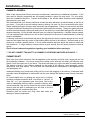
The Briarwood
By
Blaze King
Model
BRII/90
Insert
Solid Fuel Heater
Residential
Approved
LISTED BY:
READ THIS MANUAL PRIOR TO INSTALLATION OR OPERATION OF THIS APPLIANCE.
PLEASE KEEP THESE INSTRUCTIONS FOR FUTURE REFERENCE.
Manufactured By Blaze King
In Canada
Valley Comfort Systems
In USA
Blaze King Industries
1290 Commercial Way
Penticton, BC
V2A 3H5
Phone: (250) 493-7444
Fax: (250) 493-5833
146 A Street
Walla Walla, WA
99362
Phone: (509) 522-2730
Fax: (509) 522-9803
To Our Valued Customers
Dear Customer:
Thank you for purchasing the BRIARWOOD II, wood burning insert (hereafter
referred to as "stove").
This owner's manual explains the steps required to safely assemble, install,
operate, and maintain your new stove. Be a responsible stove owner; PLEASE
CAREFULLY READ THIS ENTIRE MANUAL BEFORE YOU INSTALL AND USE
YOUR NEW STOVE. FAILURE TO FOLLOW THESE INSTRUCTIONS MAY
RESULT IN PROPERTY DAMAGE, BODILY INJURY, OR EVEN DEATH.
Obtain permits from the Building Inspector or Fire Department, if local laws
require. Check local building and fire codes before installing your stove. When
the installation has been completed by a qualified, licensed installer, have it
checked by your local inspector.
Disregarding inspection and code
requirements may jeopardize your homeowner's insurance. Since some
insurance carriers require notification of a stove installation, contact your
insurance agent. We want your stove to give you many years of trouble-free
operation.
While we have made every effort to make these instructions as complete as
possible, some installation or operating conditions may not be covered. If you
have any questions that are not answered here, contact your BLAZE KING
dealer, Local Building Inspector, Fire Department, or our customer service
department at Blaze King, Walla Walla, WA (509) 522-2730 (in Canada (250)
493-7444).
Thank you for your purchase,
The Management and Employees of
Blaze King
OM-BRII/90I.PUB
Page 2
Rev. Date: Nov 27, 2003
Printed: February 8, 2005
Table Of Contents
Description
Page #
General Information ................................................................................................................................... 4-8
Warranty ...........................................................................................................................................4
Approval Label ..................................................................................................................................5
Safety ................................................................................................................................................6
Warnings .......................................................................................................................... 6-7
Maintenance .....................................................................................................................................8
Baffle ....................................................................................................................................8
Door Gasket.........................................................................................................................8
Door Adjustment ..................................................................................................................8
Ashes ...................................................................................................................................8
Fuel ......................................................................................................................................8
Creosote ..............................................................................................................................8
Installation ................................................................................................................................................ 9-12
Location ............................................................................................................................................9
Floor Protection ................................................................................................................................9
Clearances ........................................................................................................................................9
General Installation Instructions .....................................................................................................10
Optional Components .....................................................................................................................10
Chimney requirements.............................................................................................................. 11-12
Chimney height ...............................................................................................................................12
Chimney Draft .................................................................................................................................12
Operation .....................................................................................................................................................13
Grates .............................................................................................................................................13
First Fire ..........................................................................................................................................13
Curing Paint ....................................................................................................................................13
Starting Fire ....................................................................................................................................13
Controls ..........................................................................................................................................13
Do Not Burn ....................................................................................................................................13
Heat Output ....................................................................................................................................13
Do Not Over fire ..............................................................................................................................13
Assembly .....................................................................................................................................................14
General ...........................................................................................................................................14
Optional ..........................................................................................................................................15
Diagrams ........................................................................................................................................16
CAUTION:
HOT WHILE IN OPERATION. DO NOT TOUCH. KEEP
CHILDREN, CLOTHING AND FURNITURE AWAY. CONTACT MAY
CAUSE SKIN BURN.
READ NAMEPLATE AND INSTRUCTIONS
BEFORE OPERATING THE HEATER.
OM-BRII/90I.PUB
Page 3
Rev. Date: Nov 27, 2003
Printed: February 8, 2005
General Information—Warranty
BLAZE KING—Briarwood—LIMITED WOODSTOVE WARRANTY
WARNING: TO VALIDATE THIS WARRANTY YOU MUST COMPLETE AND RETURN THE ENCLOSED WARRANTY
CARD WITHIN 20 DAYS OF THE DATE OF PURCHASE.
WHAT THE WARRANTY COVERS:
Blaze King Industries and/or Valley Comfort Systems Inc. shall be referred to throughout this document as "Blaze King".
This warranty contains different terms which cover different parts of the stove. Blaze King warrants the STEEL COMPONENTS of this stove, which is
delivered with this warranty, against defects in material or workmanship to you, the original retail purchaser (hereafter referred to as purchaser), for a
period of up to five (5) years following the date of original retail purchase, subject to the provisions of the RESPONSIBILITIES OF THE COMPANY
below. Blaze King warrants the FAN ASSEMBLY, FRONT DOOR GASKET, and WOOD HANDLES of this stove, which is delivered with this warranty,
against defects in material or workmanship, to the purchaser, for a period of one (1) year following the date of original retail purchase, subject to the
provisions of the RESPONSIBILITIES OF THE COMPANY below. There is no warranty on paint, baffle plate, glass, gold plating or bricks. Blaze
King’s warranty policy applies only to units sold, installed and/or for use in the USA or Canada. No person is authorized to modify this
warranty or make any additional warranties on behalf of the manufacturer, Blaze King.
WHAT THE WARRANTY DOES NOT COVER:
Unless otherwise provided by law or covered by this warranty, Blaze King is not responsible for removal, transportation or re-installation of any product
repaired or replaced pursuant to this warranty. Blaze King shall in no event be liable for special, incidental, consequential, indirect or other similar
damages arising from the breach of the warranty, even if Blaze King has been advised of the possibility of such damages. Some states/provinces do
not allow the exclusion or limitation of incidental or consequential damages, so the above limitation or exclusion may not apply to you. Blaze King limits
all implied warranties, if any, including the warranties of merchantability or fitness for particular purpose, to one (1) year from the date of original retail
purchase. Some states/provinces do not allow limitations on how long implied warranty lasts, so the above limitation may not apply to you. Actions for
breach of this warranty must be brought within one (1) month of the expiration of this warranty. Blaze King is not responsible for installation and
operational problems such as over-firing, use of improper fuel (corrosive driftwood, etc...), spillage or downdrafts caused by environmental conditions
like trees, buildings, hilltops, mountains, or inadequate venting or ventilation, excessive offsets, negative air pressures caused by mechanical systems
such as furnaces, fans, clothes dryers, etc.
HOW YOU CAN GET SERVICE:
If this product requires repair or replacement due to defects in material or workmanship covered by this warranty, contact your Blaze King dealer and
explain the defect. If the dealer does not repair or replace the product to your satisfaction, contact the Service Department of Blaze King in the U.S.A.
at 1-509-522-2730 and in Canada at 1-250-493-7444 or write to Blaze King at one of the addresses at the end of this warranty. Please explain the
defect and state the model, serial number, date of retail purchase, and the name and address of your Blaze King dealer. Blaze King may request that
the defective part, parts, or the entire stove, be shipped to one of Blaze King's manufacturing locations at the purchaser’s expense.
WARPING:
Blaze King stoves have been thoroughly tested under extreme conditions, only abuse and over firing may create noticeable warping of components.
Over firing of your stove will void all warranties implied or otherwise.
RESPONSIBILITIES OF THE COMPANY:
If the purchaser has complied with all of the terms and conditions of this warranty and if the purchaser has notified Blaze King of a defect prior to the
expiration of the respective warranty period and after shipment, Blaze King will either repair or replace the product, AT ITS ELECTION, or MAY ELECT
to refund a portion of the purchase price, based on the formula below, if it cannot readily and quickly provide the purchaser with a replacement. The
repaired product or replacement will be shipped to a Blaze King dealer nearest the purchaser at Blaze King's expense. If it is determined by Blaze King
that there is no defect, or that the defect resulted from causes not within the scope of this warranty, then the purchaser must bear the cost of storing the
product and of returning the product to the purchaser. For parts of this woodstove or fireplace insert warranted beyond the first year, Blaze King will
have the same obligations as described in this paragraph, provided, however, that the purchaser shall pay the following percentage of the then-current
retail cost of the repair or the replacement, according to the year after purchase in which the defect is brought to the attention of Blaze King: during the
2nd year—purchaser pays 20%, during the 3rd year—purchaser pays 40%, during the 4th year—purchaser pays 60%, during the 5th year—purchaser
pays 80%
This warranty is conditional upon the proper installation and use of the stove according to the manufacturer’s directions embodied in the Owner’s
Installation and Operation Instructions published by Blaze King and in compliance with the local building or fire codes in the area where it is installed.
The stove should be inspected by the Local Building Inspector or Fire Department prior to beginning use. A copy of the Owner’s Installation and
Operation Instructions is provided with each unit, or can be obtained by contacting Blaze King. READ THE OWNER’S INSTALLATION AND
OPERATION INSTRUCTIONS BEFORE INSTALLING OR USING THE STOVE. SAVE THESE INSTRUCTIONS FOR FURTHER MAINTENANCE
AND SAFETY PROCEDURES. Alteration of, abuse of, damage to, lack of maintenance of, faulty repair, OR misuse of the stove, VOIDS this warranty.
Use of fuel other than natural untreated wood (such as artificial logs, wood exposed to salt water, or coal that may burn at excessively high
temperatures or may release fumes that can explode) will VOID this warranty. Burning the stove with the loading door open (other than during the brief
start-up period) will also VOID this warranty.
OTHER LEGAL RIGHTS OF THE PURCHASER:
This warranty gives you specific legal rights, and you may have other rights that vary from province to province or state to state. All parts of this
warranty are to be interpreted in accordance with the laws of British Columbia/Canada and or Washington State/U.S.A.. If you do not agree to the
terms and conditions set out in this warranty, then you must return the stove to the dealer prior to use or installation, and the purchase price will be
refunded.
OM-BRII/90I.PUB
Page 4
Rev. Date: Nov 27, 2003
Printed: February 8, 2005
General Information—Approval Label
BRIARWOOD II/90 INSERT
WH-
LISTED SOLID FUEL BURNING FIREPLACE INSERT
MODEL: BRII/90 Tested to : UL 1482-1998 / ULC S628-M93
CERTIFIED IN BOTH UNITED STATES AND CANADA
PREVENT HOUSE FIRES- Install and use only in accordance with Blaze King’s installation and operation instructions. Install and use in a code
complying fireplace only. Stainless steel flue liner is required in Canada and recommended in the United States. Contact local building or fire
officials about restrictions and installation inspection in your area.
Minimum Clearances To Combustibles
(Measured form Insert Shroud)
A—Side to Combustible Wall
B—Top to Mantel
C—Side to Combustible Facing
4 in / 102 mm
10.5 in / 267 mm
1 in / 25 mm
FLOOR PROTECTION
If this unit is installed on a hearth that is flush with a combustible
surface, then R1.1 protection is required for 19” in front of the door
opening and 8” on the sides. If this unit is installed on a hearth
elevated 3” or more from a combustible surface, then 18” of noncombustible floor protection is required in front of the door opening
and 8” on the sides.
Electrical rating: 115 VAC, 60 Hz, 0.58 Amps. Risk of electrical shock.
Disconnect power before servicing unit. Do not route power cord in front of
or beneath heater.
Do not remove bricks or mortar in masonry fireplace. For use with solid wood fuel only. Do not use grate or elevate fire.
Inspect and clean chimney frequently.
U.S. ENVIRONMENTAL PROTECTION AGENCY- Certified to comply with July, 1990 particulate emission standards.
*Operate with doors closed. Open door to feed fire ONLY. *Do not obstruct combustion air openings.
* Use only high temperature ceramic glass if replacement is necessary, 5 mm thick.
For use with solid fuel only. Other fuels may cause a house fire or endanger your safety.
DO NOT OVERFIRE! IF HEATER OR CHIMNEY GLOWS YOU ARE OVERFIRING.
INSPECT AND CLEAN CHIMNEY FREQUENTLY. UNDER CERTAIN CONDITIONS OF USE, CREOSOTE BUILDUP MAY
OCCUR RAPIDLY.
CAUTION:
HOT WHILE IN OPERATION. DO NOT TOUCH. KEEP CHILDREN, CLOTHING AND
FURNITURE AWAY. CONTACT MAY CAUSE SKIN BURNS. READ THIS LABEL AND INSTRUCTION
MANUAL BEFORE OPERATING HEATER.
MANUFACTURED IN:
USA:
Blaze King Industries
146A Street
Walla Walla, WA.
99362
MANUFACTURE DATE
Canada:
Valley Comfort Systems
1290 Commercial Way
Penticton, B.C.
V2A 3H5
JAN
FEB
MAR
APR
MAY
JUN
JUL
AUG
SEP
OCT
NOV
DEC
2001
2002
2003
2004
2005
2006
0165
OM-BRII/90I.PUB
Page 5
Rev 08/2001
Rev. Date: Nov 27, 2003
Printed: February 8, 2005
General Information—Safety
BRIARWOOD Model BRII/90 - Fireplace Insert
Residential Approved
Briarwood Room Heaters have been developed, tested and constructed in accordance with the requirements of
UL 1482-1998 / ULC S628-M93. Safety testing was performed by Intertek Testing Services laboratories. These
units are designed as safe and efficient, solid fuel burning heaters, but they must be properly installed and
operated. This manual describes the installation and operation of your new stove; carefully read and follow all
of the requirements and instructions included.
This heater meets the U.S. Environmental Protection Agency's emission limits for non-catalytic wood heaters
built on or after July 1, 1990. Under specific test conditions this heater has been shown to deliver heat at rates
ranging from 10,600 - 36,000 BTU/Hr.
We strongly recommend that you hire a licensed installer to properly install your Briarwood stove. In the USA
technicians are certified by the Hearth Products Association, in Canada technicians are certified by WETT.
Contact your local building inspector before your installation begins to ensure that you comply with all local
building and fire codes. Have your installation safety inspected before you put your stove into operation.
SAFETY NOTICE:
IF THIS HEATER IS NOT PROPERLY INSTALLED, A HOUSE FIRE MAY RESULT. FOR YOUR SAFETY,
FOLLOW THE INSTALLATION INSTRUCTIONS. CONTACT LOCAL BUILDING OR FIRE OFFICIALS
ABOUT RESTRICTIONS AND INSTALLATION REQUIREMENTS IN YOUR AREA.
WARNING!
MOST HOME FIRES CAUSED BY WOODBURNING STOVES ARE THE RESULT OF IMPROPER
INSTALLATION AND OPERATION.
READ ALL INSTRUCTIONS THOROUGHLY BEFORE INSTALLING AND OPERATING YOUR
Briarwood II STOVE.
SAVE THESE INSTRUCTIONS.
SAFETY PRECAUTIONS:
1.
2.
3.
4.
5.
Consult your local building inspector to ensure compliance with building and fire codes.
Design your installation with safety as the primary consideration.
Finish the installation completely before putting your stove into operation.
Use only prescribed material for your installation.
Use floor protection which meets the minimum measurements and clearances as shown on page 9 (must
be installed with the heater).
6. The Briarwood stove is designed for burning wood only.
7. Create a safety zone around the stove where children may not enter, carefully supervise youngsters when
they are in the same room with the stove.
8. The stove will be hot when burning properly, and will set objects such as clothing and curtains, on fire if
they touch it. Keep anything flammable away from the heater.
WARNING: BE ABSOLUTELY SURE THAT THE DISTANCE BETWEEN THE HEATER AND ANY
COMBUSTIBLE MATERIAL IS NOT LESS THAN THAT SHOWN ON THE APPROVAL LABEL.
9. Be sure everyone is aware of high surface temperatures and avoid contact with skin or clothing and
combustible items to avoid ignition.
10. Do not dry clothing on or near the stove.
11. Do not let anyone operate the stove who is not familiar with its operation. .
12. NEVER USE CHEMICALS, GASOLINE, GASOLINE TYPE LANTERN FUEL, KEROSENE, CHARCOAL
LIGHTER FLUID OR SIMILAR LIQUIDS TO START OR "FRESHEN UP" A FIRE IN THIS HEATER.
KEEP ALL SUCH LIQUIDS WELL AWAY FROM THE HEATER WHILE IT IS IN USE.
OM-BRII/90I.PUB
Page 6
Rev. Date: Nov 27, 2003
Printed: February 8, 2005
General Information—Safety
13. Provide for adequate fresh air supply in the room while the stove is in operation.
14. Do not leave the house unattended for long periods of time when the stove is in operation.
15. Make sure pipe connections cannot accidentally come apart. Use sheet metal screws to secure pipe
connections.
16. Clean your chimney and associated components regularly. Do not allow excessive build-up of ashes
in the stove, or allow ashes to spill from the stove when the door is opened.
17. Check masonry chimneys for cracks which may allow back-puffing and fumes to re-enter the house.
Inspect for excessive creosote build-up frequently.
18. Have your stove installation safety inspected before you build a fire in it the first time.
19. If you cook on your stove top, have a proper fire extinguisher close at hand to extinguish grease fires.
Never use water to control a grease fire. Also be careful to keep handles on pots and pans from
extending beyond the stove where they may be accidentally knocked over.
20. Install a smoke detection alarm system, and a CO (carbon monoxide) detector in your home. Smoke
detectors should not be installed in front of the stove as small spills of smoke may set them off.
21. Every home should have a fire extinguisher. Consult local fire officials or an authorized fire
extinguisher company for proper equipment. Ensure all residents know its location and how to use it.
22. For further information on using your heater safely, obtain a copy of the National Fire Protection
Association publication, "Using Coal and Wood stoves Safely", NFPA Number HS-6-1974. The
address of the NFPA is: 470 Atlantic Avenue, Boston, MA 02210.
23. For further information, refer to NFPA 211.
24. Do not over fire your woodstove. Although the Briarwood II is designed to heat efficiently, it should
never be fired to a red-hot condition.
25. This heating appliance is not to be connected to any “Air Distribution Duct”.
26. Do not store firewood, kindling or any other combustible materials within the clearances on this stove.
See page 9 or the label on the stove for clearance information.
27. This stove must not be operated with the loading door open, other than for loading fuel. Operating this
stove with the loading door open could cause a house fire or personal injury.
28. Do not abuse, strike or slam the loading door, as the glass may break and will not be covered under
warranty.
29. This stove shall not be operated with cracked or broken glass.
30. Do not clean glass while it is hot. Do not clean glass with abrasive cleaners.
31. If replacement parts are required, substitute materials are prohibited and will void your warranty.
32. Do not use fuels in this stove other than solid wood. Use of other fuels such as coal, charcoal or
others, will void your warranty and may cause damage to the stove, a house fire or personal injury.
33. Never remove brick or mortar from fireplace or chimney. Install warning plate—see bottom of page 9.
35. The installer must permanently seal any opening between the masonry of
the fireplace and the facing masonry (see figure to the right).
36. SAVE THESE INSTRUCTIONS.
Chimney
34. Makeshift compromises made during installation of chimney liner may
jeopardize safety or cause a house fire.
Brick
Fireplace
Opening
THE INFORMATION CONTAINED HEREIN IS BELIEVED TO BE ACCURATE. HOWEVER,
NO RESPONSIBILITY FOR ERRORS OR OMMISIONS IS ASSUMED BY BLAZE KING INC.
OM-BRII/90I.PUB
Page 7
Rev. Date: Nov 27, 2003
Printed: February 8, 2005
General Information—Maintenance
REMOVABLE BAFFLE PLATE
The baffle is the part of the stove which receives the most heat. For this reason, as well as for chimney cleaning ease,
it has been made to be easily removed. Remove the screws on each side of baffle and the bolt from the rear center of
the stove, this will allow the baffle to slide forward and out. The baffle plate may be damaged by over firing and burning
improper fuels. Baffle plate damage is not covered by warranty. To order replacement baffles please call your dealer
with the model and serial number of your stove.
GASKET REPLACEMENT
Door gasket: Inspect gaskets frequently for leakage and deterioration. To replace damaged gasket, first remove old
gasket and clean channel thoroughly. Apply stove gasket adhesive in channel and press the 7/8" dense fiberglass
rope gasket into channel, (begin and end in lower right corner ensuring a tight fit where the two ends join). Close door
tightly and fire the stove to set the seal. The door latch is adjustable if necessary. Visually inspect periodically,
throughout the heating season to ensure an airtight seal.
GLASS REPLACEMENT
Do not slam the loading door or otherwise impact the glass. If the glass gets cracked or broken, it must be replaced
before using the stove. Replacement parts can be obtained from your authorized Blaze King dealer. The glass is a
5mm high temperature ceramic, substitute materials are not permitted. As a general rule, whenever you replace the
glass on your stove, your gaskets should be replaced as well. To replace the glass let your stove cool down, never
handle a hot door or hot glass. After the door and glass is cool to touch, remove the door from the stove. Remove the
door gasket, glass retainer and gasket and the old glass. Use caution when handling broken glass, it can be very
sharp. Install the new glass complete with gasket in your door. Please ensure that the glass retainer is properly
secured to the door to provide a good seal. Do not over-tighten the screws, this can damage the glass. To learn more
about replacing your door gasket, read the above section on gasket replacement.
ASHES
Your stove works best when you consistently maintain a good bed of coals, although ash build-up does need to be
cleaned out periodically. Remember that a wood fire does burn best with about a half inch of ashes.
Disposal of ashes: Ashes should be placed in a metal container with a tight fitting lid. The closed container of ashes
should be placed on a non-combustible material pending final disposal. If the ashes are disposed of by burial in soil or
otherwise locally disposed, they should first be retained in the closed container until all cinders have thoroughly cooled.
WET OR GREEN FUEL
Wet or green fuel should not be used. Wood should be cut into pieces and allowed to air dry for several months before
attempting to burn it. After the wood supply is cured (dry), ensure it is protected from rain and snow so that moisture is
not absorbed. However, if you do add wet or green fuel to an existing fire, open the draft control to intensify the fire and
burn off moisture. When completed return the draft control to desired operating position. You will not get much heat
output from your stove while burning green or wet fuel, a large amount of the energy produced by the fire is used to
evaporate the moisture from the fuel load, this energy is wasted and will not come into your home. REMEMBER, WET
OR GREEN FUEL CAUSES INCREASED CREOSOTE FORMATION.
CREOSOTE - Formation and Need for Removal
When wood is burned slowly, it produces tar and other organic vapors, which combine with expelled moisture to form
creosote. The creosote vapors condense in the relatively cool chimney flue of a slow burning fire. As a result,
creosote residue accumulates on the flue lining. When ignited this creosote makes an extremely hot fire.
The chimney connector and chimney should be inspected at least once every two months during the heating season to
determine if a creosote buildup has occurred.
IF CREOSOTE HAS ACCUMULATED IT SHOULD BE REMOVED TO REDUCE THE RISK OF A CHIMNEY FIRE.
Creosote build-up may be minimized by using dry, seasoned wood, especially hardwoods. Avoid burning green wood
at any time, but especially during periods of slow burning such as overnight. Recommended burning practices also
reduce creosote build-up. It has been found that opening the draft controls to allow the fire to burn freely for 3- 4 hours
in your stove each week will cut down on creosote build-up. Open the draft controls each time fuel is added and allow
the fire to flame a few minutes before closing the draft controls again. After an overnight burn, open the draft controls
and allow the fire to flame hot for five or ten minutes with dry kindling.
Remember, these practices are to reduce creosote build-up. If creosote has built up already, have the chimney cleaned
immediately. If a creosote fire should develop close the air intake, call the fire department immediately, and ensure
that all persons are out of the house and safe. After a severe chimney fire, the complete chimney system and
connecting pipes must be checked by a qualified person before further use.
OM-BRII/90I.PUB
Page 8
Rev. Date: Nov 27, 2003
Printed: February 8, 2005
Installation—Location & Clearances
YOUR STOVE'S LOCATION
1. Plan ahead to be certain that furniture will have ample clearance, and that drapes and curtains
cannot come in contact with the room heater. Refer to the approval label on the stove for correct
clearances to combustibles.
2. This stove must be connected to a chimney. It must be vented to the outside. Never permit your
stove to ventilate itself into any room in the building.
3. Consult illustrations below and the approval label to ensure that you install your stove the proper
minimum distances from combustible materials.
4. Minimum fireplace size is 28” (w) x 22” (h) x 14” (d)
Minimum Clearances To Combustibles
(Measured form Insert Shroud)
4 in / 102 mm
10.5 in / 267 mm
1 in / 25 mm
B
A—Side to Combustible Wall
B—Top to Mantel
C—Side to Combustible Facing
A
28-3/8 in
720.7 cm
C
19-1/4 in
488.9 cm
43 in/109.2 cm
FLOOR PROTECTION
If this unit is installed on a hearth that is flush with a combustible surface, then R1.1
protection is required for 19” in front of the door opening and 8” on the sides. If this
unit is installed on a hearth elevated 3” or more from a combustible surface, then 18”
of non-combustible floor protection is required in front of the door opening and 8” on
the sides.
BEFORE YOU PUT YOUR STOVE IN PLACE, YOU
MUST ATTACH THE WARNING PLATE THAT WAS
INCLUDED WITH YOUR STOVE (SHOWN TO THE
RIGHT).
THIS LABEL PLATE MUST BE
ATTACHED TO THE INSIDE WALL OF YOUR
FIREPLACE.
OM-BRII/90I.PUB
Page 9
Rev. Date: Nov 27, 2003
Printed: February 8, 2005
Installation—General
BRIARWOOD II INSERT STOVE INSTALLATION PROCEDURE
AFTER YOU READ AND FULLY UNDERSTAND THE MATERIAL IN THIS MANUAL, YOU ARE
READY TO PROCEED WITH THE INSTALLATION OF YOUR STOVE.
SAFETY NOTICE: IF THIS HEATER IS NOT PROPERLY INSTALLED, A HOUSE FIRE MAY
RESULT. FOR YOUR SAFETY, FOLLOW THE INSTALLATION DIRECTIONS. CONTACT
LOCAL BUILDING OR FIRE OFFICIALS ABOUT RESTRICTIONS AND INSTALLATION
REQUIREMENTS IN YOUR AREA.
Before beginning the installation, thoroughly clean and inspect the fireplace and chimney
you are using. Professional assistance is recommended, your local certified installer
should be contacted to provide installation and inspection services. Check the fireplace
and insert dimensions to ensure the insert will fit properly. While planning your installation
keep in mind the required clearances on page 9 of this manual.
To ensure safe proper operation, Listed Stainless Steel Flue Liners are required for
installation in Canada and recommended in the United States. Check your local codes and
regulations before installing.
BRIARWOOD II OPTIONAL COMPONENTS
Your Briarwood Insert is listed for use
with the following components:
Z1514b - Optional Fans
0845 - Shroud Trim
ZBR561G - Gold Door Trim
Custom Made Adaptor
Plate To Fit Fireplace
OM-BRII/90I.PUB
Page 10
Rev. Date: Nov 27, 2003
Printed: February 8, 2005
Installation—General
INSTALLATION INTO FACTORY BUILT FIREPLACES
In addition to the general instructions presented throughout the manual you must take care to
ensure the following steps are correct when installing this insert into a factory built fireplace.
1) The factory built fireplace must be listed per UL127 or UL S620.
2) All clearances to combustibles must be maintained as shown on the label.
3) The installation must include a full-length liner, which is attached to the insert and to the chimney
cap.
4) Means must be provided to prevent room air passage to the chimney cavity of the fireplace. This
may be accomplished by sealing the damper area around the chimney liner, or sealing the fireplace
front.
5) The airflow within and around the fireplace shall not be altered by the installation of the insert
(i.e.: no louvers or cooling air outlet ports are blocked).
No alterations of the factory built fireplaces are allowed except as follows:
a) External trim which do not affect the operation of the fireplace may be removed providing
they can be stored on or within the fireplace for reassembly if the insert is removed.
b) The chimney damper may be removed to install the chimney liner.
6) Circulating air chambers in a steel fireplace liner or metal heat circulator shall not be blocked.
7) Means must be provided for removal of the insert to clean the chimney flue.
8) If the insert protrudes from the front of the fireplace a supporting means must be installed and all
clearance requirements met.
9) A permanent metal warning label must be attached to the back of the fireplace stating that the
fireplace must be restored to the original condition for safe use without the insert.
INSTALLATION: CHIMNEY
CHIMNEYS: FACTORY-BUILT FIREPLACE
In Canada and in the U.S.A.: If the insert is installed into a factory built fireplace the chimney must be
lined from the outlet of the insert to the top of the chimney with a Stainless Steel liner which meets UL1777
or ULC S635. The liner must be securely attached to the insert and the chimney top.
CHIMNEYS: MASONRY FIREPLACE
In Canada: A code approved masonry chimney with a 6” listed stainless steel flue liner system and the
accompanying vent connector is required.
In U.S.A.: A code approved masonry chimney with appropriate vent connector extending from the flue
collar of the stove to the first chimney flue liner and adaptor plate. A full length listed flue liner system with
vent connector is recommended for all installations.
OM-BRII/90I.PUB
Page 11
Rev. Date: Nov 27, 2003
Printed: February 8, 2005
Installation—Chimney
CHIMNEYS: GENERAL
Refer to the chimney and chimney connector manufacturer’s instructions for additional information. If this
stove and its chimney components are not properly installed, a house fire may result. For your safety,
follow the installation directions. Contact local building or fire officials about restrictions and installation
requirements in your area.
We recommend that your chimney should be at least the same dimension (inside diameter) as the flue of
your stove. If you plan to use an existing masonry chimney, be sure it is free of cracks and loose joints.
Gases traveling through a chimney reach extremely high temperatures. Cracks or loose mortar can allow
hot gases to reach the wood portion of the structure surrounding the chimney. These toxic gases may also
re-enter the house through cracks and small holes in the chimney, or cause back-puffing which will result in
excessive smoking. Be on the safe side and have your chimney inspected by a certified chimney sweep.
A 6 inch stainless steel chimney liner with a direct connection to the stove is recommended for masonry
chimney installations.
A chimney must reach at least three feet above the highest point where it passes through the roof and at
least two feet higher than any portion of the building within ten feet of the chimney. Smoke travels up the
chimney in a circular, spiraling motion. A 6 inch round stainless steel liner allows the smoke to travel with
less resistance. A rough masonry chimney without a good smooth liner will cause creosote to build up
quickly.
Check all local codes and regulations regarding your installation before you begin.
*** DO NOT CONNECT THIS UNIT TO A CHIMNEY FLUE SERVING ANOTHER APPLIANCE. ***
CHIMNEY DRAFT
Draft is the force which moves air from the appliance up the chimney and pulls fresh, oxygen-rich air into
the combustion chamber. Your stove cannot force smoke up the chimney but rather your chimney must
always "suck" the smoke out of your stove. The smoke will always try to go to the area of lowest pressure.
The amount of draft in your chimney depends on the length of the chimney, local geography, nearby
obstructions, and other factors. Too much draft can cause excessive temperatures in the appliance and
may damage the unit.
Inadequate drafting may cause back puffing into the room and plugging of the chimney. Inadequate draft
may also cause the appliance to leak smoke into the room through the appliance and chimney connector
joints.
An uncontrollable burn or glowing red stove part or chimney
connector indicates excessive draft. Unit failure to "get hot", or
"burn hot", or if you experience poor burn times, can be the
result of inadequate chimney draft or excessive chimney draft.
In most instances if the stove is vented into an exterior masonry
chimney and the draft is inadequate you will need to line the
outside chimney with a stainless steel liner.
Excessive draft can create over firing, short burn times and
damage to internal components.
OM-BRII/90I.PUB
Page 12
Rev. Date: Nov 27, 2003
Printed: February 8, 2005
Operation—General
ANDIRONS OR GRATES - (Not For Use On The Briarwood Insert)
Briarwood Stoves are designed for the burning of wood directly on the firebrick. Best efficiency and burn
characteristics are obtained when a half-inch bed of ashes is maintained in the firebox.
STARTING YOUR FIRST FIRE (Curing Your Stove Paint)
Make sure you provide extra ventilation by opening a door or window as the paint will give off fumes while it is curing.
There will be some paint odor during your first few fires. To cure the paint on your stove you should build a small
kindling fire, let it die down; build another fire, slightly larger, let it die down; build yet another fire, slightly larger
(stove should be fairly hot by this point). Do not over fire your woodstove for the next few fires - this should
sufficiently cure the paint. If you should have any blistering or peeling of paint, it can be sanded down and repainted
with high temperature stove paint, available in aerosol cans from your local dealer. NOTE: The paint is not covered
by the warranty.
STARTING A FIRE
"DO NOT TAMPER". It is against the law to alter this wood heater. This heater is designed for clean burning in
accordance with rules and regulations of the U.S. Environmental Protection Agency. "It is against the law to operate
this wood heater in a manner inconsistent with operating instructions in this manual."
CAUTION: NEVER USE GASOLINE, LANTERN FUEL OR KEROSENE, CHARCOAL LIGHTER FLUID OR
SIMILAR LIQUIDS TO START OR FRESHEN UP A FIRE IN THIS HEATER. KEEP ALL FLAMMABLE LIQUIDS A
SAFE DISTANCE FROM YOUR STOVE.
1. Make sure the draft control is on the high setting, see illustration below. Clean any coals away from the starter
manifold at the front of the firebox as they may create an obstruction of starter air to the fuel.
2. Place several pieces of "wadded up" or "balled" paper in the firebox.
3. Place several pieces of small, dry, finely split kindling on the paper.
4. Light the paper in several places and hold the door partially open (usually 1-2 inches) until the kindling is ignited
adequately to sustain combustion with the door closed. Never leave the stove unattended unless the door is
properly closed and latched.
5. Allow the fire to burn until an adequate bed of coals is formed.
6. You may now place several larger pieces of wood on the fire. In order to insure complete combustion of the
organic compounds released from the wood, load the fuel as far back in the firebox as possible. Also, the
charcoal bed can be sloped slightly towards the rear so that the fuel does not tend to fall forward. Close the door
with the draft control open until a robust fire occurs.
7. Operate on high setting for at least 5 minutes or until combustion will sustain at
High
starter manifold before closing draft to desired setting. After refueling operate with Low
blower "off" for at least 30 minutes.
CONTROLS
Draft Control
This stove is equipped with a combustion air control (draft control) located beneath the
door opening. This control regulates the heat output and burn time of the stove. Closing the setting restricts the
incoming combustion air for minimum heat output and maximum burn duration. The further open the setting, the
faster the fuel will burn and the higher the heat output.
This heater is designed to burn natural cord wood only. Higher efficiencies and lower emissions generally result
when burning air dried seasoned hardwoods, as compared to softwoods or too green or freshly cut hardwoods.
DO NOT BURN
Do not burn treated wood, solvents, coal, colored paper, garbage, trash, cardboard, board ends, plywood, composite
boards, etc…
CAUTION: Do not burn board ends, kiln dried lumber, etc. for other than kindling purposes. Extended use
may damage the stove and void warranties.
HEAT OUTPUT
The heat output of this stove depends on the amount of wood used, the type and dryness of wood used, the size of
smoke path leading from the woodstove and the amount of air entering the woodstove.
DO NOT OVER FIRE YOUR HEATER
Although your woodstove has been designed to heat efficiently and operate at high temperatures, it is meant to
supplement other heating means in your home, and it should never be fired to a red hot condition. Once the
woodstove is in use, it should be checked frequently to be sure that it is operating at the temperature range you have
selected.
OM-BRII/90I.PUB
Page 13
Rev. Date: Nov 27, 2003
Printed: February 8, 2005
Assembly—General
Assembly Instructions for Briarwood II/90 Insert
There will be local building and fire codes which could affect this installation. Be sure you check with your local building inspector, fire inspector or other
local authorities having jurisdiction in your area before you begin installation. This insert is certified only for installation into a masonry fireplace which
has been carefully inspected and is in good condition.
Blaze King recommends that you use a qualified Blaze King installer to assemble and properly install your Briarwood insert. Technicians are certified
by the HPA in the USA and by WETT in Canada.
Provide protection for the hearth to prevent damage while sliding the heavy insert in and out of the fireplace opening.
1] Carefully remove and inspect the insert parts from the shipping packages. Ensure there is no freight damage and you have all the parts required.
2] Remove the 4 bolts in the back of the shield box, remove the 5 #10 screws from the top of the shield box and slide the shield box off of the firebox.
3] Place the outer shield box (Fig. 6) into your fireplace opening and ensure that the bottom of the box is level with or slightly higher than your hearth.
Use only non-combustible material to fill any space under the shield box. Exact placement of the shield box will be established in the next steps
and is determined by the overall shape of your fireplace.
4] IF YOU HAVE PURCHASED THE OPTIONAL GOLD TRIM KIT PROCEED TO “OPTIONAL INSTALLATION INSTRUCTIONS” ON THE NEXT
PAGE TO INSTALL THE TRIM BEFORE PROCEEDING TO THE NEXT STEP.
5] The shroud (fig 8) is shipped with the side extensions removed, they must be assembled on the shroud at this time. To attach the side extensions
place the short side of the “L” shaped extension against the back of the shroud and attach with 3 screws (see Fig. 5 for correct placement of side
extensions). Slide the shroud (fig 8) complete with the side extensions (fig 4) into the shield box. The side extensions (fig 4) and the inside flange
on the shroud, must slide inside the shield box.
6] Slide the assembly in until the shroud (fig 8) is against the front face of the fireplace. The shield box is adjustable to fit most fireplaces and flues.
When the shield box is in the best location proceed to the next step.
7] When you are sure of the correct placement, secure the side extensions to the shield box using 3 sheet metal screws through the pre punched
holes in the shield box. Note: you will have to pre-drill 1/8” holes in the side extensions using the shield box holes as templates.
8] While you have the shroud in place measure carefully to ensure you have adequate minimum clearances to all combustible material. Clearances
to combustibles are listed on the appliance label.
9] Disassemble the shroud (fig 8) from the side extensions (fig 6) and carefully set the shroud aside. The shield box is now sitting at its final position
and the side extensions are firmly attached to the shield box.
10] Remove the shield box assembly, (which now has the side extensions (fig 4) attached to it), from the fireplace opening. Leave the side extensions
(fig 4) securely attached to the shield box (fig 6) in the correct position as established in step 7.
11] Slide the firebox (fig 7) into the shield box (fig 6) and attach it to the firebox using 4 bolts and washers through the back of the shield box. It may
be necessary to remove the shield box top to allow the firebox flue collar to slide into the shield box. Replace the shield box top when the firebox
is in place inside the shield box.
12] Your insert comes without a fan. An electrical harness is provided for future installation. (Note: It is necessary to use the grommets where the wire
passes through the holes on each of the shroud parts to avoid damage to the wire.) IF YOU PURCHASED THE OPTIONAL FANS GO TO
“OPTIONAL INSTALLATION INSTRUCTIONS” ON THE NEXT PAGE BEFORE PROCEEDING TO INSTALL THE FANS.
13] If you have not purchased the optional fans you must now install the fan housing pieces (fig. 1). The housing attaches with 2 screws top & bottom
with the large round hole facing out.
14] Blaze King strongly recommends that you install a complete Stainless Steel flue liner system. This is the safest installation and will ensure proper
draft control for best burn conditions and consistency.
15] If you have the flue liner installed check to ensure it is the proper length etc. If you decide to use an adapter plate in the throat of your existing
fireplace you should install it at this time and install the connector pipe as required. You must follow all local building and fire codes regarding this
installation. Proceed only after you have completed the required work on the flue system.
16] Carefully slide the complete assembly (firebox mounted inside the shield box) into the fireplace opening at the same position as previously
determined. The unit weighs approx. 300 lbs. and you will require help. Be careful not to damage the wire running around the back of the box, do
not allow it to get pinched under the shield box as you slide the assembly into the fireplace opening. You will need to protect the hearth so it does
not get damaged when sliding the unit in or out.
17] Connect the flue system to the insert firebox flue collar using three sheet metal screws. Place a bead of furnace cement around the flue collar
connection and ensure the flue pipe is properly connected, secured and sealed.
18] Re install the shroud front and carefully adjust the firebox placement to ensure the required fit around the shroud and against the fireplace facing.
When sliding the shroud into place ensure that the rear flange on the shroud goes under the top of the shield box. Attach the shroud to the side
extensions using three sheet metal screws and flat washers on each side. (Fig 8)
19] Install the fan front covers (fig 2), attach rheostat knob if fan kit installed, and connect the AC cord as required. See electrical diagrams (Fig 11).
20] Install the shroud lid (fig 3) using four sheet metal screws to attach it to the shroud and the fan covers.
21] Install the hearth protection in front of your insert as required by the minimum clearances noted on the appliance safety label. Do not fire your
insert unless you have the proper clearances and protection of combustible material as required by the safety label.
22] Recheck your installation carefully. Have your installation inspected by the authority having jurisdiction. See the operation manual for firing
instructions and have a nice cozy winter.
OM-BRII/90I.PUB
Page 14
Rev. Date: Nov 27, 2003
Printed: February 8, 2005
Assembly—General / Optional
OPTIONAL INSTALLATION INSTRUCTIONS
Optional Gold Trim Installation:
Assemble the trim strips as shown in (fig 12) and attach to the shroud outer edge using the screws provided.
to step 4 and continue the installation.
Return
Optional Fans Installation: (Note: The following instructions pertain to both fans on the left and right sides of the stove.)
1. Determine which side of the stove the power cord for the fan should be located.
2. Install a grommet in the 5/8” hole on each side of the shroud. Install a grommet in the bottom 5/8” hole of the fan
housing piece (Fig. 1 on page 16) which will contain the rheostat.
3. Slide the wires, which are attached to the shield box, through the grommets on the shroud. Note: It may be easier
to slide the wire with the larger male connector through first.
4. Install Bomax fan (with printing on fan right side up) and finger screen (Fig. 21). The fan attaches from the front, to
the fan housing, with the finger screen attaching under the outside 2 fan mounting screws. The screen will need to
be bent to act as a finger protector (Fig. 21).
5. Mount the rheostat, with 2 screws, as shown in Fig. 21. Connect the green ground wire by using the green screw
& star washer provided, be sure to place the star washer between the round lug & the frame of the housing. Insert
a wire, from the rheostat, with a male connector and a wire with a female connector through the grommet in the
fan housing, connect these 2 wires to the male and female connectors on the shield box wiring harness. Connect
the remaining male & female connectors to the fan. Connect shield box wiring harness, on other side of unit, to fan
on other side using same method.
6. Proceed to step 13 on page 14.
See the electrical diagram (Fig 11 on page 16)
for electrical connection.
Note: the fans are connected in parallel.
17”
Fig 12
Optional Gold Trim
Top
L-Brackets X2
Right
Left
Screw
Brass Screws X2
Screw
Fig 20
OM-BRII/90I.PUB
Fig 21
Page 15
Rev. Date: Nov 27, 2003
Printed: February 8, 2005
Assembly—Diagrams
OM-BRII/90I.PUB
Page 16
Rev. Date: Nov 27, 2003
Printed: February 8, 2005
NOTES
OM-BRII/90I.PUB
Page 17
Rev. Date: Nov 27, 2003
Printed: February 8, 2005