1
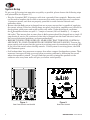
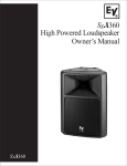
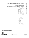
Sx A Series
Powered Loudspeakers
Owner’s Manual
SxA100+
SxA250
SxA180
ELECTRO-VOICE® Owner’s Manual
IMPORTANT SAFETY INSTRUCTIONS
The lightning flash with arrowhead symbol, within an equilateral triangle
is intended to alert the user to the presence of uninsulated “dangerous
voltage” within the product’s enclosure that may be of sufficient
magnitude to constitute a risk of electric shock to persons.
The exclamation point within an equilateral triangle is intended to alert
the user to the presence of important operating and maintenance
(servicing) instructions in the literature accompanying the appliance.
1.
2.
3.
4.
5.
6.
7.
Read these instructions.
Keep these instructions.
Heed all warnings.
Follow all instructions.
Do not use this apparatus near water.
Clean only with a damp cloth.
Do not block any of the ventilation openings.
Install in accordance with the manufactures instructions.
8. Do not install near any heat sources such as radiators, heat registers, stoves, or other apparatus that produce heat.
9. Only use attachments/accessories specified by the manufacturer.
10. Refer all servicing to qualified service personnel. Servicing is required when the apparatus has been damaged in
any way, such as power-supply cord or plug is damaged, liquid has been spilled or objects have fallen into the
apparatus, the apparatus has been exposed to rain or moisture, does not operate normally, or has been dropped.
For US and CANADA only:
Do not defeat the safety purpose of the grounding-type plug. A grounding type plug has two blades and a third
grounding prong. The wide blade or the third prong are provided for your safety. When the provided plug does
not fit into your outlet, consult an electrican for replacement of the absolete outlet.
IMPORTANT SERVICE INSTRUCTIONS
CAUTION: These servicing instructions are for use by qualified personnel only. To reduce the risk of electric
shock, do not perform any servicing other than that contained in the Operating Instructions unless you are
qualified to do so. Refer all servicing to qualified service personnel.
1. Security regulations as stated in the EN 60065 (VDE 0860 / IEC 65) and the CSA E65 - 94 have to be obeyed
when servicing the appliance.
2. Use of a mains separator transformer is mandatory during maintenance while the appliance is opened, needs
to be operated and is connected to the mains
3. Switch off the power before retrofitting any extensions, changing the mains voltage or the output voltage.
4. The minimum distance between parts carrying mains voltage and any accessible metal piece (metal
enclosure), respectively between the mains poles has to be 3 mm and needs to be minded at all times.
The minimum distance between parts carrying mains voltage and any switches or breakers that are not
connected to the mains (secondary parts) has to be 6 mm and needs to be minded at all times.
5. Replacing special components that are marked in the circuit diagram using the security symbol (Note) is only
permissible when using original parts.
6. Altering the circuitry without prior consent or advice is not legitimate.
7. Any work security regulations that are applicable at the location where the appliance is being serviced have
to be strictly obeyed. This applies also to any regulations about the work place itself.
8. All instructions concerning the handling of MOS - circuits have to be observed.
Note:
1
SAFETY COMPONENT (HAS TO BE REPLACED WITH ORIGINAL PART ONLY)
ELECTRO-VOICE® Owner’s Manual
Table of Contents
SxA Owner’s Manual .................................................................................................................. 2
Safety First ................................................................................................................................. 3
Description .................................................................................................................................. 4
System Features – Sx A Two-Way Systems................................................................................ 4
System Features - Sx A 180 Powered Woofer ............................................................................. 4
System Setup .............................................................................................................................. 5
Setup Diagrams for Sx A Two-Way Systems ............................................................................. 6
Sx A180 Woofer System Setup .................................................................................................... 8
F22 Monitor Foot Accessory ..................................................................................................... 11
System Specifications ............................................................................................................... 12
Electro-Voice® Uniform Limited Warranty ............................................................................. 13
Sx A Owner’s Manual
Thank you for choosing Electro-Voice® Sx A active powered loudspeaker systems.
These systems are the culmination of EV’s 75 years of experience in transducer
design and over 50 years of experience in designing and building electronics.
Please take time to consult this manual so that you can understand all the
features built into your EV systems and fully utilize all their performance
capabilities.
ELECTRO-VOICE® Owner’s Manual
2
Safety First
When setting up, installing and using Electro-Voice® Sx A speaker systems, there are a
number of precautions that you should follow:
When Electro-Voice® Sx A speakers are used for portable applications in which they will be
stacked directly on the floor or mounted on a tripod stand, make sure that the floor or
stage is solid and secure.
Electro-Voice® Sx A speaker systems include 1 3/8-inch stand mounts to allow mounting on
tripod stands.
Make sure to:
Check the specifications of the speaker stand to be certain it is capable of supporting the
weight of the speaker.
Check that the speaker stand is placed on a flat, stable surface and be sure to fully extend
the legs of the stand. Do not try to make the stand “taller” and compromise its structural
integrity.
Route cables and position the stand so that performers, production crew and audience
members will not trip over the stand or cables and pull the speaker system over. Secure
cables with wire ties or tape whenever possible.
Do not attempt to suspend more than one speaker on a stand designed for a single
speaker.
Unless you are confident that you can safely handle lifting the weight of the speaker onto
the stand, ask another person to help you place it.
After the system is in operation for a few minutes, the heat sink will become warm to the
touch and can become quite hot after extended high-level operation. Avoid touching the
heat sink fins to prevent burns. When installing the system, use care to ensure that there
is at least two inches of space behind the heatsink to allow free circulation of air.
If you intended to hang or fly the Sx A two-way systems, please do so safely with the correct
hardware and accessories.
·
·
·
·
·
·
·
·
·
WARNING: Suspending any object is potentially dangerous and should only be
attempted by individuals who have a thorough knowledge of the techniques and
regulations of rigging objects overhead. Electro-Voice® strongly recommends that Sx A
speakers be suspended taking into account all current national, federal, state and local
regulations. It is the responsibility of the installer to ensure that Sx A speakers are safely
installed in accordance with all such regulations. If Sx A speakers are suspended, Electro-Voice®
strongly recommends that the system be inspected at least once a year. If any sign of weakness
or damage is detected, remedial action should be taken immediately. Please consult our
manual entitled Suspending System 200 Loudspeakers, and the SK1 data sheet, which details
the various hardware kits that are available to safely suspend Sx A speakers and how each kit
should be used. There are also data sheets for each EV hanging hardware part that should
also be consulted prior to suspending speakers.
·
·
3
Electro-Voice® does not recommend use of Sx A speakers outdoors or in high
moisture environments. Avoid exposing Sx A speakers to direct moisture and or
high humidity that can cause corrosion of electrical contacts and problems with
loudspeaker cones and surrounds.
Electro-Voice® Sx A loudspeakers are easily capable of generating sound pressure
levels sufficient to cause permanent hearing damage to anyone within normal
coverage distance. Caution should be taken to avoid prolonged exposure to sound
pressure levels exceeding 90 dB.
ELECTRO-VOICE® Owner’s Manual
Description
Electro-Voice® Sx A series powered loudspeakers are fully integrated audio systems with
carefully matched electronics and transducers. These products make it easy to setup a highquality sound system quickly with a minimum of cables and external electronics. They retain
typical EV ruggedness, reliability and impeccable sound quality.
System Features – SxA Two-Way Systems
·
·
·
·
·
·
·
·
·
Integrated mixer/crossover/amplifiers/speaker system with separate mic and line inputs,
EQ and line-level outputs.
Two built-in power amplifiers, one for low frequencies and one for high frequencies. The
amplifiers also contain electronic crossover circuitry and CD horn compensation optimized
for the speaker components a well as a limiter circuit that prevents either amplifier from
clipping while preserving the sonic quality.
The low-frequency power amplifier delivers 150 watts continuous average power and 350
watts dynamic power (IHF A). Dynamic output power is important because it determines
the transient capability of the system.
The high-frequency power amplifier delivers 50 watts continuous average power and 80
watts dynamic power (IHF A). This provides more than 3 dB of headroom over the
continuous current capabilities of the high-frequency driver.
The line input utilizes Neutrik “combo” connectors, which will accept either ¼-inch or 3pin XLR-type connectors.
The mic input is balanced, low-impedance 3-pin XLR-type
The separate line output is 3-pin XLR-type balanced, low-impedance output that can be
used with long cable runs.
Two-band EQ provides tonal shaping to compensate for program material, room acoustics
and personal taste.
Sx A two-way systems are perfect for use as powered floor monitors.
System Features - SxA 180 Powered Woofer
·
·
·
·
·
·
·
·
Integrated power amplifier, electronic crossover and low-frequency speaker designed to
add extended bass to Sx A systems
Class D amplifier with 300 watts continuous average power, 650 watts dynamic power
(IHF-A). A built-in limiter prevents serious amplifier clipping and minimizes the potential
for speaker damage.
18-inch EV DL woofer with 2.5-inch voice coil for reliable low-frequency output to 38 Hz.
Line input with balanced 3-pin XLR-type connector
Crossover with continuously variable low-pass frequency from 80 Hz to 120 Hz
Filtered high-pass output and paralleled full-range output on balanced 3-pin XLRtype connectors.
Storage compartment with detachable dolly board and casters for easy transportation. The
dolly board covers a storage compartment that holds a 34-inch pole and has ample space
for cables, etc.
Comes with 34-inch pole for elevating any EV speaker system with 1 3/8-inch
stand mount.
ELECTRO-VOICE® Owner’s Manual
4
System Setup
To get your Sx A system into operation as quickly as possible, please observe the following steps
and precautions (see Figures 3-7)
Plug the 3-terminal IEC 16-gauge ac cable into a grounded line receptacle. Extension cords
can be used to lengthen the ac cable as necessary but make sure that they are 3-conductor
14 gauge or greater, and that are properly grounded to avoid electrical hazards and
extraneous noise.
Be sure that the Sx A system is plugged into an ac power source that is capable of supplying
the correct voltage. If the line voltage drops too much, the built-in amplifiers won’t be able to
develop their rated power and sound quality will suffer. Under high signal conditions,
the Sx A amplifier section can pull 2 – 4 amps of current (120 volt models) (1 – 2 amps at
240 volts). That means that no more than 4-Sx A systems should be plugged into a single 15
amp electrical service. Be cautious of what else is plugged into the same electrical service
line to avoid electrical problems and poor performance.
BEFORE TURNING THE POWER ON, MAKE SURE THAT THE LEVEL CONTROLS
ARE DOWN TO AVOID TRANSIENTS OR UNEXPECTED LOUD SOUND. Turn on the
power switch and ensure that the system is receiving power by monitoring the status LED
to the left of the switch above the EQ controls. If the system is receiving power, the LED
will illuminate green.
SxA loudspeakers have narrower coverage than other compact loudspeaker systems. Their
narrower coverage will help you avoid room acoustics problems by delivering the sound
where the speaker is aimed. You will find that precisely aiming the speakers at the
audience area away from walls will give you better sound quality.
·
·
·
·
5
Figure 1:
Figure 2:
Rear Panel SxA100+ and SxA250
Rear Panel SxA180
ELECTRO-VOICE® Owner’s Manual
Setup Diagrams for SxA Two-Way Systems
To use the Sx A two-way system for various applications:
Plug a microphone into the microphone input connector (See Figure 3). It will only accept
low-impedance dynamic microphones terminated with a standard 3-pin XLR-type
connector. Turn the gain control clockwise until the signal present LED stays on with the
input signal at normal operational level. Adjust the master gain control to the desired
overall output level.
Plug a line input into either the ¼-inch or the 3-pin XLR-type input connector. Examples
of line input sources are mixer outputs, CD/DVD players, cassette decks, VCRs,
electronic keyboards, computer sound cards, etc. The ¼- inch input is in the center of the
XLR connector and can accept unbalanced or balanced lines (TRS ¼-inch). The line input
level required to drive the unit to full power is from – 12 dBu to 0 dBu. The system’s
master gain control regulates the overall output level of the system.
·
·
THRU Output
Figure 3:
Microphone Input Connections
& Connections To Additional Systems
ELECTRO-VOICE® Owner’s Manual
6
Setup Diagrams for SxA Two-Way Systems (cont.)
you are using the Sx A two-way system with a microphone and a line input
· Ifsimultaneously,
it is simple to balance the two signals. The microphone level control has
·
·
·
enough gain and range so that it is possible to mix the mic input and the line input. Once
the balance between the line and mic inputs is set, simply turn the Gain Master control to
the desired level.
If there is no sound, keep the overall system gain at a reduced level until you determine
what the problem may be. Typically, a mixer mute switch may be engaged or a
microphone that is switched off is the source of the problem. Keeping the system gain at a
low level will allow you to troubleshoot the problem and let you hear the results without
unexpected bursts of sound or howling feedback. Start with the low-frequency and highfrequency EQ controls set in the flat position (12 o’clock, middle position) and listen to
your program material before making any changes. Be aware that boosting EQ requires
additional amplifier power and may reduce the acoustic output potential of the system
somewhat. Use EQ judiciously.
To route the signal to additional Sx A systems, simply hook an XLR-type cable from the line
output connector on the source system to the line input connector on each additional Sx A
system. The signal can be cascaded into a large number of Sx A systems without
degradation.
When turning your system off, turn off the Sx A systems first. This will prevent any turnoff transients from other pieces of equipment from being amplified.
To cascade the signal to extra Sx A twoway systems, simply run a cable from
the line output on the source system to
the line input.
Left Line Level
Output
Right Line
Level Output
Mixer
Figure 4:
Mixer Line Connections
7
ELECTRO-VOICE® Owner’s Manual
Sx A180 Woofer System Setup
To get your woofer system into operation as quickly as possible, please observe the following
steps and precautions:
Plug the 3-terminal IEC 16-gauge ac cable into a grounded line receptacle. Extension
cords can be used as necessary but make sure that they are the 3-conductor type that are
14 gauge or greater, and are properly grounded to avoid electrical hazards and
extraneous noise.
Turn on the power switch and ensure that the system is receiving power by monitoring the
status LED power on. MAKE SURE THAT THE LEVEL CONTROLS ARE TURNED
DOWN TO AVOID TRANSIENTS OR UNEXPECTED LOUD SOUND.
Attach a 3-pin XLR cable to the line-level input from a line-level output on your mixer.
If you are using the Sx A180 with an Sx A two-way system, you will want to use the highpass output to run the signal from the Sx A180 to the two-way (See Figure 5). Using the
filtered output will insure that the Sx A180 only is reproducing low bass information which
will let the two-way system sound cleaner and play louder. The unfiltered output is the
best way to parallel the signal to other Sx A180s or if you want more mid-bass output from
the speaker setup.
·
·
·
·
Input Signal
From Mixer
Figure 5:
Panel Close-up
ELECTRO-VOICE® Owner’s Manual
8
Sx A180 Woofer System Setup (cont.)
·
After you have confirmed that the signal is present, adjust the level control and the
crossover frequency. The selection of a crossover frequency will depend on room acoustics
and your particular sonic taste. In general, a lower crossover frequency will result in a
more linear, “hi-fi” sound and a higher crossover frequency will give your sound
more “thump.”
To Input
Line
Power
Cord
Line-level
Hi-pass
out
To Input
From
High-Pass
Output
SxA180
plays the low
frequencies
Power
Cord
Full
Range
From
Mixer
Output
Figure 6:
Rear View
9
ELECTRO-VOICE® Owner’s Manual
Sx A180 Woofer System Setup (cont.)
To Input
Line
To Input
Line
To Input
Line
Line-level
Hi-pass
out
Line-level
Hi-pass
out
Line-level
Hi-pass
out
To Input
To Input
From
HighPass
Output
Power
SxA180 Cord
plays the low
frequencies
Power
Cord
Power
Cord
Power
Cord
To Input
From
HighPass
Output
From
HighPass
Output
SxA180
plays the low
frequencies
Power
Cord
Power
SxA180 Cord
plays the low
frequencies
From
Mixer
Output
Full
Range
Figure 7:
Cascade Signal in Multiple Box Hook Up
ELECTRO-VOICE® Owner’s Manual
10
Using Two-Way SxA Systems as Floor Monitors
Sx A two-way systems are perfect for use as powered floor monitors.
The correct projection angle is already incorporated into the enclosure design of the Sx A250.
Simply turn the Sx A250 on its side and operate the system in the same manner as described
above. The F200 adapters are necessary to convert the Sx A100+ into a monitor and are
shipped with the speaker. To install the adapters, simply insert them into the speaker (See
Figure 8 below). The F200 adapters can be easily removed by pulling in the opposite
direction.
The F200 Monitor Foot kit contains two plastic feet.
The F200 is used with any 12-inch Sx or Sx A speaker enclosures.
Insert the feet firmly into the holes in the rear cabinet (See Figure 8).
Remove the F200 monitor feet by pulling in the opposite direction.
“O” RING
LOCATION
MONITOR
FOOT
PERMANENT SCREW
LOCATION
FIGURE 8:
Installing the F200 Monitor Foot on SxA100+ Speaker
CAUTION: The F200 monitor feet protrude from the enclosure. Care should be taken
when moving the enclosure, since damage to the feet or enclosure might occur if the
system is dropped or slid across a rough surface. It is recommended that the feet be
removed for transport.
11
®
ELECTRO-VOICE
Owner’s Manual
Manual
ELECTRO-VOICE® Owner’s
ELECTRO-VOICE® UNIFORM LIMITED WARRANTY
Electro-Voice® products are guaranteed against malfunction due to defects in materials or workmanship
for a specified period, as noted in the individual product-line statement(s) below, or in the individual
product data sheet or owner’s manual, beginning with the date of original purchase. If such malfunction
occurs during the specified period, the product will be repaired or replaced (at our option) without
charge. The product will be returned to the customer prepaid. Exclusions and Limitations: The
Limited Warranty does not apply to: (a) exterior finish or appearance; (b) certain specifics described
in the individual product-line statement(s) below, or in the individual product data sheet or owner’s
manual; (c) malfunction resulting from use or operation of the product other than as specified in the
product data sheet or owner’s manual; (d) malfunction resulting from misuse or abuse of the product;
or (e) malfunction occurring at any time after repairs have been made to the product by anyone other
than Electro-Voice or any of its authorized service representatives. Obtaining Warranty Service: To
obtain warranty service, the customer must deliver the product, prepaid, to Electro-Voice or any of its
authorized service representatives together with proof of purchase of the product in the form of a bill
of sale or receipted invoice. A list of authorized service representatives is available from ElectroVoice® . Incidental and Consequential Damages Excluded: Product repair or replacement and
return to the customer are the only remedies provided to the customer. Electro-Voice® shall not be
liable for any incidental or consequential damages including, without limitation, injury to persons
or property or loss of use. Some states do not allow the exclusion or limitation of incidental or
consequential damages so the above limitation or exclusion may not apply to you. Other Rights:
This warranty gives you specific legal rights and you may also have other rights, which vary from
state to state.
Electro-Voice® Speakers and Speaker Systems are guaranteed against malfunction due to
defects in materials or workmanship for a period of five (5) years from the date of original
purchase. The Limited Warranty does not apply to burned voice coils or malfunctions such as cone
and/or coil damage resulting from improperly designed enclosures. Additional details are included
in the Uniform Limited Warranty statement.
Service and repair addresses for this product:
Telex Communications, 1 Telex Drive, Morrilton, Arkansas 56013 (501-354-0111)
World Headquarters:
Electro-Voice®, 12000 Portland Avenue South, Burnsville, Minnesota 55337 (952-884-4051)
13
ELECTRO-VOICE® Owner’s Manual
NOTES
ELECTRO-VOICE® Owner’s Manual
14
U.S.A. and Canada:
For customer orders, contact the Customer Service department at:
800/392-3497 Fax: 800/955-6831
For warranty repair or service information, contact the Service Repair Department at:
800/685-2606
For technical assistance, contact Technical Support at:
866/78 AUDIO
Specifications subject to change without notice.
All Locations:
952-884-4051 Fax: 952-884-0043
www.electrovoice.com
Telex Communications, Inc.
www.telex.com
Printed in U.S.A
© Telex Communications, Inc. 1/2002
Part Number 38110-088 Rev A
ELECTRO-VOICE® Owner’s Manual