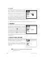
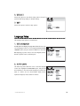
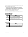
1
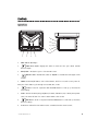
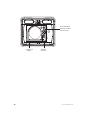
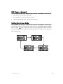
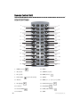
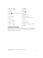
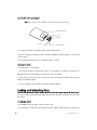
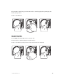
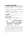
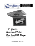
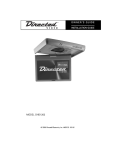
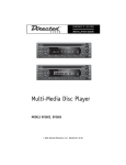
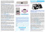
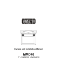
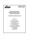
OWNER’S GUIDE
INSTALLATION GUIDE
9” (16:9)
Overhead Video
Monitor/DVD Player
MODEL OHD901A
© 2005 Directed Electronics, Inc. N82901A 03-05
NON-TRANSFERABLE LIMITED CONSUMER WARRANTY
Directed Electronics, Inc. (Directed) promises to the original purchaser that the automotive video monitor
and/or source unit(s) (the Product), excluding accessories, purchased and installed from a Directed
authorized dealer within ninety (90) days after purchase of the new vehicle, in which the Product is
installed, will be free from defects in materials or workmanship under normal use and conditions for a period of three (3) years from date of purchase or the first 36,000 miles as registered on the new vehicle's
odometer reading at time of delivery of the Product for warranty service, whichever occurs first. Product
purchased or installed more than ninety (90) days after the new vehicle is purchased are warranted for a
period of one (1) year from date of purchase of the Product.
Directed promises to the original purchaser that all video accessories will be free from defects in materials and workmanship under normal use and condition for a period of ninety (90) days after the date of
purchase. A sales receipt and/or warranty registration card is required to provide proof of date of purchase
of the Product or accessories.
Should the Product prove to be defective during the applicable warranty period, the Product will be
repaired or replaced with a new or comparable reconditioned part(s), at Directed's election. To obtain warranty service, the Product must be returned to a Directed authorized dealer along with proof of purchase
and proof of installation by an Authorized Directed Dealer.
Note: This warranty does not cover labor costs for the removal and/or reinstallation of the Product. IN
ORDER FOR THIS WARRANTY TO BE VALID, YOUR PRODUCT MUST BE SHIPPED WITH PROOF OF
PURCHASE AND INSTALLATION BY AN AUTHORIZED DIRECTED DEALER. ALL PRODUCTS
RECEIVED BY DIRECTED FOR WARRANTY REPAIR WITHOUT PROOF OF DIRECTED DEALER
INSTALLATION WILL BE DENIED.
This warranty is non-transferable and does not apply to any Product that has been modified or used in a
manner contrary to its intended purpose, and does not cover damage to the Product caused by installation or removal of the Product. This warranty is VOID if the product has been damaged by accident or
unreasonable use, negligence, acts of God, neglect, improper service or other causes not arising out of
defect in materials or construction. This warranty does not cover the elimination of externally generated
static or noise, or the correction of antenna problems or weak television reception, damage to tapes, video
games, software, camcorders, discs, speakers, accessories or vehicle electrical systems, cosmetic damage or damage due to negligence, misuse, abuse, failure to follow operating instructions, accidental spills
or customer applied cleaners, damage due to environmental causes such as floods, airborne fallout,
chemicals, salt, hail, windstorms, lightning or extreme temperatures, damage due to accidents, road hazards, fire, theft, loss or vandalism, damage due to improper connection to equipment of another manufacturer, modification of existing equipment, damage caused by faulty media or the cleaning of components, or Product which has been opened or tampered with for any reason or which has been damaged
due to alteration or service performed by anyone other than Directed Electronics, Inc.
ALL WARRANTIES INCLUDING BUT NOT LIMITED TO EXPRESS WARRANTY, IMPLIED WARRANTY, WARRANTY OF MERCHANTABILITY, FITNESS FOR PARTICULAR PURPOSE, AND WARRANTY
OF NON-INFRINGEMENT OF INTELLECTUAL PROPERTY ARE EXPRESSLY EXCLUDED TO THE
MAXIMUM EXTENT ALLOWED BY LAW, AND DIRECTED NEITHER ASSUMES NOR AUTHORIZES
ANY PERSON TO ASSUME FOR IT ANY LIABILITY IN CONNECTION WITH THE SALE OF THE
PRODUCT. DIRECTED HAS ABSOLUTELY NO LIABILITY FOR ANY AND ALL ACTS OF THIRD
PARTIES INCLUDING ITS LICENSED DEALERS OR INSTALLERS. IN NO EVENT WILL DIRECTED
ELECTRONICS, INC. BE LIABLE FOR ANY INCIDENTAL, SPECIAL OR CONSEQUENTIAL DAMAGES (INCLUDING LOSS OF PROFITS), BY PURCHASING THIS PRODUCT, THE CONSUMER
AGREES AND CONSENTS THAT ALL DISPUTES BETWEEN THE CONSUMER AND DIRECTED
SHALL BE RESOLVED IN ACCORDANCE WITH CALIFORNIA LAWS IN SAN DIEGO COUNTY, CALIFORNIA.
Some states do not allow limitation on how long an implied warranty lasts. In such states, the limitations
or exclusions of this Limited Warranty may not apply. Some states do not allow the exclusion or limitation
of incidental or consequential damages. In such states, the exclusion or limitation of this Limited Warranty
may not apply to you. This Limited Warranty gives you specific legal rights, and you may have other rights
which vary from state to state.
March 01, 2005
2
© 2005 Directed Electronics, Inc.
Table of Contents
Non-Transferable Limited One Year Consumer Warranty . . . . . . . . . . . . . . . . . . . . . . 2
Safety Instructions and Cautions . . . . . . . . . . . . . . . . . . . . . . . . . . . . . . . . . . . . . 5
Welcome . . . . . . . . . . . . . . . . . . . . . . . . . . . . . . . . . . . . . . . . . . . . . . . . . . . . .6
What’s Included . . . . . . . . . . . . . . . . . . . . . . . . . . . . . . . . . . . . . . . . . . . . . . . . 6
Important . . . . . . . . . . . . . . . . . . . . . . . . . . . . . . . . . . . . . . . . . . . . . . . . . . . . 6
When Cleaning the Vehicle .............................................................................6
While Driving ...............................................................................................6
When Parked ................................................................................................7
Proper Use ...................................................................................................7
Disc Handling and Cleaning ............................................................................7
Repairs ........................................................................................................7
Radio/TV Tuner Use .......................................................................................7
Installation ..................................................................................................7
Picture Quality..............................................................................................8
Important Information . . . . . . . . . . . . . . . . . . . . . . . . . . . . . . . . . . . . . . . . . . . . 8
FCC Notice ...................................................................................................8
Your Warranty ...............................................................................................8
Controls . . . . . . . . . . . . . . . . . . . . . . . . . . . . . . . . . . . . . . . . . . . . . . . . . . . . . . 9
Monitor .......................................................................................................9
DVD—Mounted............................................................................................10
DVD—UnMounted ........................................................................................12
DVD—Memory Card Mounting ........................................................................13
DVD Player—Installation . . . . . . . . . . . . . . . . . . . . . . . . . . . . . . . . . . . . . . . . . 13
DVD Player—Removal . . . . . . . . . . . . . . . . . . . . . . . . . . . . . . . . . . . . . . . . . . . . 15
Setting the Screen Mode . . . . . . . . . . . . . . . . . . . . . . . . . . . . . . . . . . . . . . . . . . 15
Remote Control Unit . . . . . . . . . . . . . . . . . . . . . . . . . . . . . . . . . . . . . . . . . . . . 16
Remote Buttons ..........................................................................................16
IR Remote Feedthrough................................................................................17
Battery Replacement....................................................................................18
Precautions ................................................................................................18
Loading and Unloading Discs . . . . . . . . . . . . . . . . . . . . . . . . . . . . . . . . . . . . . . 18
Loading Disc...............................................................................................18
Unloading Disc............................................................................................19
Operating the Monitor . . . . . . . . . . . . . . . . . . . . . . . . . . . . . . . . . . . . . . . . . . . 20
Open/Close the Display Monitor.....................................................................20
Power Up/Down the Display Monitor . . . . . . . . . . . . . . . . . . . . . . . . . . . . . . . . . 21
Source (Mode) ............................................................................................21
Menu (Console Menu)...................................................................................21
Door Light On/Off .......................................................................................22
Courtesy Light On/Off ..................................................................................22
Basic Functions . . . . . . . . . . . . . . . . . . . . . . . . . . . . . . . . . . . . . . . . . . . . . . . . 23
© 2005 Directed Electronics, Inc.
3
DVD Playback..............................................................................................23
Play/Pause (DVD/MP3/CD) ............................................................................24
Stop (DVD/MP3/CD).....................................................................................24
Selecting a Track or Chapter..........................................................................25
MP3 and JPEG Playback on CD or Memory Card ................................................25
Playback Programming .................................................................................26
Advanced Playback (DVD/MP3/CD) .................................................................27
Setup . . . . . . . . . . . . . . . . . . . . . . . . . . . . . . . . . . . . . . . . . . . . . . . . . . . . . . . 28
Accessing Setup Menus . . . . . . . . . . . . . . . . . . . . . . . . . . . . . . . . . . . . . . . . . . . 28
System Setup . . . . . . . . . . . . . . . . . . . . . . . . . . . . . . . . . . . . . . . . . . . . . . . . . 29
1. TV System .............................................................................................29
2. Screen Saver ..........................................................................................29
3. TV Type.................................................................................................30
4. Password ...............................................................................................30
5. Rating (Parental Settings)........................................................................30
6. Default .................................................................................................31
7. Exit ......................................................................................................31
Language Setup . . . . . . . . . . . . . . . . . . . . . . . . . . . . . . . . . . . . . . . . . . . . . . . . 31
1. OSD Language ........................................................................................31
2. Audio Lang ............................................................................................31
3. Subtitle Lang .........................................................................................32
4. Menu Lang.............................................................................................32
Installation Guide . . . . . . . . . . . . . . . . . . . . . . . . . . . . . . . . . . . . . . . . . . . . . . 32
Precautions ................................................................................................32
Electrical Connections ..................................................................................33
Signal Connection........................................................................................34
Typical Wiring Diagram.................................................................................35
Installation Procedure . . . . . . . . . . . . . . . . . . . . . . . . . . . . . . . . . . . . . . . . . . . 36
System Wiring Diagram Example . . . . . . . . . . . . . . . . . . . . . . . . . . . . . . . . . . . . 38
Troubleshooting . . . . . . . . . . . . . . . . . . . . . . . . . . . . . . . . . . . . . . . . . . . . . . .39
Specifications . . . . . . . . . . . . . . . . . . . . . . . . . . . . . . . . . . . . . . . . . . . . . . . . . 41
4
© 2005 Directed Electronics, Inc.
Safety Instructions and Cautions
WARNING: TO REDUCE THE RISK OF FIRE OR ELECTRIC SHOCK, DO NOT EXPOSE THIS EQUIPMENT TO RAIN OR MOISTURE. TO REDUCE THE RISK OF FIRE OR ELECTRIC SHOCK AND
ANNOYING INTERFERENCE, USE ONLY THE INCLUDED HARDWARE.
THIS MONITOR IS ONLY DESIGNED FOR REAR SEAT PASSENGER VIEWING AND IS NOT
INTENDED FOR VIEWING BY THE DRIVER WHILE THE VEHICLE IS IN MOTION. SUCH USE MAY
DISTRACT THE DRIVER OR INTERFERE WITH THE SAFE OPERATION OF THE VEHICLE, AND
MAY ALSO VIOLATE STATE LAW.
DIRECTED ELECTRONICS, INC. DISCLAIMS ANY LIABILITY FOR ANY BODILY INJURY,
INCLUDING FATALITIES, OR PROPERTY DAMAGE THAT MAY RESULT FROM ANY IMPROPER OR
UNINTENDED USES OF THIS PRODUCT.
SHOULD THE LCD PANEL BREAK OR LEAK FLUID, AVOID ALL CONTACT WITH THE UNIT. IF
YOU SHOULD COME IN CONTACT WITH THE LEAKED FLUID, WASH THE AFFECTED AREA
THOROUGHLY WITH WATER AND SEEK IMMEDIATE MEDICAL ATTENTION.
DO NOT CLOSE THE LCD SCREEN IF A MEMORY CARD HAS BEEN INSERTED INTO THE DVD
PLAYER. THIS CAN CAUSE THE LCD PANEL TO BREAK OR LEAK FLUID (SEE ABOVE WARNING). REMOVE MEMORY CARD(S) BEFORE CLOSING SCREEN.
■
During operation, if the unit should over-heat or malfunction, switch off the unit and see your
dealer. Do not disassemble the unit as there are no user-serviceable parts in this unit and the warranty will be voided.
■
Should there be a need to replace a blown fuse, turn off the unit and disconnect all power to
the player. Use only the correct rating fuse to avoid electrical damage to the unit.
■
Only operate the monitor as described in this guide. Attempts to use or modify this monitor
contrary to the descriptions in this guide may cause damage and void the warranty.
■
Extremes in temperature can cause abnormal display operation. This monitor has an optimal
operating temperature range between 32–120 degrees Fahrenheit. If the vehicle interior is outside
this range, do NOT operate the monitor until the temperature is within its operating range.
■
Exposure to moisture or dust can cause harmful damage to the internal electronics. Do not
mount near cup holders or in areas where spills may occur.
■
This monitor is designed for use in vehicles with standard (-) 12 volt ground electrical systems.
■
Do not operate for an extended period of time without the engine running or the vehicle’s bat-
tery voltage may drop to levels precluding engine starting.
■
Do not drop the LCD panel or subject it to direct impact. This will damage the panel and/or
the back light element.
© 2005 Directed Electronics, Inc.
5
■
When operating the unit, avoid contact with the LCD panel.
■
Prevent metal or foreign objects being locked between the LCD screen and the enclosure.
Foreign objects may impair smooth running of the disc and may cause electrical problems.
■
Keep unit away from equipment with strong magnets such as large loudspeakers.
■
To prevent malfunction, do not play discs other than the ones listed below: DVD audio discs, CD-
ROMs, JPEGs, MP3s and DVDs with region numbers other than this player's region number.
Welcome
Thank you for your purchase of Directed’s Overhead Monitor with integrated DVD. Prior to operating
this unit, please fully read this instruction manual and retain it for future reference.
What’s Included
The following items are included with your purchase:
z Monitor with DVD Player
z Power Harness
z A/V Switch Box
z DIN Cable
z (2) Headphones
z Domelight Harness
z Remote Control
z Mounting Trim Bezel
z Mounting Plate (with 4 screws)
z A/V Cable for DVD Player
z AC/DC Adapter for DVD Player
Important
WHEN CLEANING THE VEHICLE
Do not spray this unit with water or cleaning solutions. Moisture and the chemicals found in cleaning
fluids could damage the consoles finish and interior electronics. A soft damp, lens cleaning cloth
should be used to wipe the screen. Do NOT use any type of scouring pad, abrasive cleaners, or solvents.
WHILE DRIVING
This unit is intended for use in the rear seat area only. It is illegal in some jurisdictions to install the
unit in a location that would allow the driver to view it while driving.
6
© 2005 Directed Electronics, Inc.
WHEN PARKED
The screen is easily visible when deployed. Always close the screen when parking for an extended
period of time to avoid potential theft or extended exposure to direct sunlight.
PROPER USE
Do not touch the screen. Do not pull or hang from the fold down monitor door.
DISC HANDLING AND CLEANING
Always handle the discs by the edge. Never touch the shiny side of the discs, as this can impair proper playback.
Mount and dismount the discs with care not to damage or scratch the shiny side of the disc. This
will cause playback faults.
Do not expose the discs to direct sunlight.
After playing, store the disc back in its case.
To clean the disc, use a clean soft lint-free cloth and wipe the disc from the center out. Do not wipe
with a circular motion. Do not use any solvents.
REPAIRS
If the monitor stops working for any reason, discontinue use immediately and consult with your
retailer about any necessary repairs.
RADIO/TV TUNER USE
When the unit is used in conjunction with a Radio/TV tuner, please assure that the receiver is manufactured to receive television broadcast signals that are transmitted via terrestrial radio waves.
Reception quality will change and vary according to vehicle location and weather conditions.
INSTALLATION
Avoid installing the monitor at a location, where it will be under direct sunlight or a hot air vent.
The operating temperature of the unit is from 32–120°F (0–50°C). Install the unit at a dry location,
where it is away from condensation.
Use only the correct size fasteners and cables during installation. Failure to do so may cause a
mechanical or electrical failure and create a fire hazard. The installation should be done by an
authorized Directed dealer.
NOTE: If the internal temperature of the vehicle is higher than the normal operating temperature, please allow the vehicle to cool down (or warm up) prior
to operating the unit.
© 2005 Directed Electronics, Inc.
7
PICTURE QUALITY
The picture quality of this LCD unit depends strictly on its installed location. To achieve the best
picture quality, adjust the brightness control or viewing angle of the unit until the optimum viewing is achieved.
Important Information
FCC NOTICE
This device complies with Part 15 of FCC rules. Operation is subject to the following two conditions:
(1) This device may not cause harmful interference, and (2) this device must accept any interference received, including interference that may cause undesirable operation.
Changes or modifications not expressly approved by the party responsible for compliance could void
the user's authority to operate this device.
YOUR WARRANTY
Your warranty registration must be completely filled out and returned within 10 days of purchase.
Your product warranty will not be validated if your warranty registration is not returned. Make sure
you receive the warranty registration from your dealer. It is also necessary to keep your proof of purchase, which reflects that the product was installed by an authorized dealer.
8
© 2005 Directed Electronics, Inc.
Controls
MONITOR
5
6
7
8
9
1
1.
2.
2
3
4
DOME LIGHTS—Quantity 2.
DOOR LIGHT On/Off—Engage this switch to have the door open switch activate
the dome lights.
3.
4.
OPEN/CLOSE—The latch to open or close the LCD screen.
COURTESY LIGHT—Activate this switch to "ON/OFF" to activate the dome lights on the
monitor.
5.
POWER—Power On/Off button, Source Select button. Hold for 3-seconds to turn power off.
Each press of this button cycles through sources DVD, AV1, or AV2.
6.
UP Button—Used in conjunction with the MENU button to scroll up (or increase) the
menu setting.
7.
MENU—Used to set FM Frequency, Brightness, Contrast, Saturation, Hue, or Reset (menu parameters). The menu will exit if no action is taken within a few seconds.
8.
DOWN Button—Used in conjunction with the MENU button to scroll down (or decrease)
the menu setting.
9.
IR Receiver—Infrared receiver which receives commands from the remote control.
© 2005 Directed Electronics, Inc.
9
DVD—MOUNTED
The illustration below shows the DVD player mounted in a typical LCD monitor.
2
3
4
5
8
9
6
10
11
13
14
1
7
12
1.
LOCK/UNLOCK—To dock or undock the DVD player.
2.
OPEN—Press this button to open the access door to mount or dismount a disc.
3.
AUDIO—Each press of this button accesses each audio track recorded on the DVD (multiple langauges, commentary, etc.)
4.
MENU—Displays the menu on the DVD. Use the Up, Down, Left, and Right buttons to scroll
through the available selections. Use the Enter button to select.
*
5.
UP—
6.
DOWN—
7.
LEFT—
8.
RIGHT—
9.
ENTER
*
*
*
*
10. PLAY/PAUSE—When pressed pauses the playback until pressed again.
11. STOP—Halts playback. If the Play button is pressed the playback will continue from where
stopped. If the Stop button is pressed twice, playback will now start from the beginning.
10
© 2005 Directed Electronics, Inc.
WARNING: DO NOT CLOSE THE LCD SCREEN IF A MEMORY CARD HAS BEEN INSERTED INTO
THE DVD PLAYER. THIS CAN CAUSE THE LCD SCREEN TO BREAK OR LEAK FLUID. IF YOU
SHOULD COME IN CONTACT WITH LEAKED FLUID, WASH THE AFFECTED AREA THOROUGHLY
WITH WATER AND SEEK IMMEDIATE MEDICAL ATTENTION. REMOVE ALL MEMORY CARDS
BEFORE CLOSING THE LCD SCREEN.
12. MS Card—Memory Stick, allows playback of music, photographs, movies, etc.
13. SD Card—Secure Digital, allows playback of music, photographs, movies, etc.
14. CF Card—Compact Flash, allows playback of music, photographs, movies, etc.
NOTE: To read from a memory card, there must not be mounted a DVD or CD in the
player and the player door must be closed. Only 1 memory card can be
inserted into the player at a time.
* These buttons are used to navigate through the menus on the screen and then use the Enter button to select the option.
© 2005 Directed Electronics, Inc.
11
DVD—UNMOUNTED
The illustration below shows the side of the DVD player when removed from the LCD monitor.
VOL
PHONE A/V OUT
DC 12V
1
1.
2
3
4
5
6
Electrical connector—This connector provides the electrical interface when mounted in the LCD
monitor.
12
2.
VOL Control—Controls the volume to the phone jack output.
3.
PHONE Jack—An optional headphone set can be connected here.
4.
A/V OUT Jack—Audio/video output jack.
5.
DC 12V Jack—Input power.
6.
IR Receiver—For receiving commands from the remote control.
© 2005 Directed Electronics, Inc.
DVD—MEMORY CARD MOUNTING
Ensure that the memory cards are mounted with the logo side of the memory cards oriented with the
arrows as shown below:
Memory Stick
Logo
Side
Logo
Side
Logo
Side
Secure Digital
Compact Flash
WARNING: DO NOT CLOSE THE LCD SCREEN IF A MEMORY CARD HAS BEEN INSERTED INTO
THE DVD PLAYER. THIS CAN CAUSE THE LCD SCREEN TO BREAK OR LEAK FLUID. IF YOU
SHOULD COME IN CONTACT WITH LEAKED FLUID, WASH THE AFFECTED AREA THOROUGHLY
WITH WATER AND SEEK IMMEDIATE MEDICAL ATTENTION. REMOVE ALL MEMORY CARDS
BEFORE CLOSING THE LCD SCREEN.
DVD Player—Installation
1.
Ensure power to the monitor is off and that the ignition key is off.
2.
Align the notches in the side of the player with the tabs in the sides of the monitor DVD mount-
ing area and slide the player into the monitor.
3.
Slide the player towards the LCD screen until the lock/unlock button latches.
NOTE: If the DVD player doesn’t power up correctly, remove the player (see instructions below) and then re-install.
© 2005 Directed Electronics, Inc.
13
Lock/Unlock
Button
14
Insert DVD Player
and then slid down
until unit locks.
Electrical
Connector
© 2005 Directed Electronics, Inc.
DVD Player—Removal
1.
While holding and supporting the DVD player.
2.
Move and hold the lock/unlock button to the right.
3.
Slide the player away from the screen and carefully remove.
Setting the Screen Mode
The overhead monitor has 4 different screen modes. These are: FULL, NORMAL, WIDE, and ZOOM.
Press the Image
button on the remote control to access the different screen modes. The last
mode set is displayed on the screen. Each time the Mode button is pressed, the screen switches in
the following sequence.
© 2005 Directed Electronics, Inc.
15
Remote Control Unit
REMOTE BUTTONS
1
4
2
3
6
7
10
11
14
15
18
19
22
23
26
27
30
31
34
35
38
39
42
43
46
47
5
8
9
12
13
16
17
20
21
24
25
28
29
32
33
36
37
40
41
44
45
1. POWER (source)
28. ANGLE
2. IR (on/off)
29. SUBTITLE (on/off)
3. FM (on/off)
30. DOWN (Cursor)
4. Picture (PIP)
(n/a in this model)
31. AUDIO
5-7. Numeric
32. ZOOM (2, 3, 4, 1/2, 1/3, 1/4, OFF)
8. UP (display)
33. F.REV (Fast Reverse)
9-11. Numeric
34. PLAY/PAUSE
12. Console MENU
35. F.FWD (Fast Forward)
13-15. Numeric
36. SLOW
16
48
© 2005 Directed Electronics, Inc.
16. DOWN (display)
37. BACK
17. MENU/PBC
38. STOP
18-19 Numeric
39. NEXT
20. Image
(wide, zoom, full, normal)
40. REPEAT
41. POWER (Tuner)*
22. UP (Cursor) 42. DSP (channel display)*
23. SETUP
43. TV/AV (selects Tuner or Aux input)*
24. MUTE (on/off)
44. DISPLAY
25. LEFT (Cursor)
21. TITLE
26. ENTER
46. CH- (channel down)*
27. RIGHT (Cursor)
45. CH+ (channel up)*
47. AUTO (auto programming of TV channels)*
48. PROGRAM
IR REMOTE FEEDTHROUGH
The remote will operate, through the monitor, and transmit commands to other compatible devices
attached to the AV1 or AV2 source at the switch-box. The IR signals are compatible with models
DV2602, DV2605 DVD players, and TV100 tuner.
* These buttons are for use only with the TV tuner (model TV100).
© 2005 Directed Electronics, Inc.
17
BATTERY REPLACEMENT
NOTE: Before using remote after installation, remove the battery plastic protective slip.
Remote Controller
+ side
Battery
Latch
Battery Holder
1. Move the small latch to the right and slide out the battery holder.
2. Remove old battery and replace it with a new battery (CR2025) with the positive “+” sign facing
as shown above.
3. Push battery holder back into its compartment until it is locked.
PRECAUTIONS
1. Properly dispose of used battery.
2. Do not misuse battery by shorting the positive “+” and negative “-” terminal or put it into fire.
Overheating may cause the battery to explode and cause a fire hazard.
3. If the remote is not to be used for a long period, remove the battery from the remote to prevent
damage from battery leakage.
4. To avoid accidents, prevent children from playing with the battery.
Loading and Unloading Discs
You can use single side and dual layer DVDs, VCDs, CD-audio and CD-R compatible 12cm discs with
this system.
LOADING DISC
1. Press OPEN at the upper right corner to open the door.
2. Load with the recorded side (the shiny side) facing up. With double-sided discs, load with the
18
© 2005 Directed Electronics, Inc.
side you want to watch facing up. Ensure that the disc is seated properly before pushing tray back
into its locking position.
3. Push to close the door.
UNLOADING DISC
1. Press OPEN at the upper right corner to open the door.
2. Remove the disc. (Avoid touching the recorded surface.)
3. Push to close the door, until you hear a click sound from the door mechanism.
© 2005 Directed Electronics, Inc.
19
Operating the Monitor
OPEN/CLOSE THE DISPLAY MONITOR
To open the display monitor, push the "OPEN" button and pull the monitor down by the middle of the
LCD to the desired position.
WARNING: THE LCD MONITOR MUST ALWAYS BE OPENED, CLOSED, OR POSITIONED FROM
THE MIDDLE OF THE SCREEN AS SHOWN BY THE POINTING HAND BELOW. DO NOT USE THE
CORNERS OF THE SCREEN, THIS CAN RESULT IN DAMAGE/LEAKAGE OF THE SCREEN.
To Open—push center button
Use this portion of the
screen for opening, closing,
and positioning.
Open Pos ition
WARNING: DO NOT CLOSE THE LCD SCREEN IF A MEMORY CARD HAS BEEN INSERTED INTO
THE DVD PLAYER. THIS CAN CAUSE THE LCD SCREEN TO BREAK OR LEAK FLUID. IF YOU
SHOULD COME IN CONTACT WITH LEAKED FLUID, WASH THE AFFECTED AREA THOROUGHLY
WITH WATER AND SEEK IMMEDIATE MEDICAL ATTENTION. REMOVE ALL MEMORY CARDS
BEFORE CLOSING THE LCD SCREEN.
To close the display monitor, push the LCD screen up until it latches closed with an audible click.
Note: The ignition key must be in the Accessory or Ignition position in order for
the monitor to have power.
20
© 2005 Directed Electronics, Inc.
Power Up/Down the Display Monitor
The unit will power up when the display monitor is unlatched and pulled down. (If the unit does
not power up, press the Power
button on either the remote or the Power button on the left
side of the LCD screen.
To turn the power off to the unit, press and hold for 3-seconds the POWER
button on the
remote or the Power button on the left side of the LCD screen. The power will also shut Off when
the display monitor is placed in the closed and latched position.
If the hand
icon or “INVALID KEY” displays in the upper left-hand corner of the screen when
using the remote, it indicates that the command issued is not allowed during the mode that the
monitor display is presently in, or is not available on this system.
SOURCE (MODE)
Press the
(SOURCE) button on the remote or momentarily press the POWER button on the left
side of the LCD screen to select the input signal AV1, AV2 or DVD.
MENU (CONSOLE MENU)
Press MENU button on the left side of the LCD screen or the
button on the remote to activate
the screen parameters set-up. The sequence of set-up items is as follows:
FM
→
SHARPNESS
→
BRIGHTNESS
SATURATION
→
→
HUE →
CONTRAST →
RESET
FM: Transmitting frequency
SHARPNESS: Sharpness adjustment
BRIGHTNESS: Brightness adjustment
CONTRAST: Contrast adjustment
SATURATION: Color saturation adj.
HUE: Color hue adjustment
RESET: Resets above (except FM) to factory default settings.
Once the desired setting is selected, press the cursor buttons to adjust the setting. On the remote
use the up/down cursor buttons located at either side of the menu button. On the monitor use the
cursor buttons to the right side of the
button. If a button is not activated within 5 seconds,
this function mode will turn OFF. Once the correct function is selected, press the cursor button (to
set the desired setting). If no button is pressed, the menu mode will turn OFF in about 5 seconds.
The FM frequency setting allows the monitor to transmit audio to the vehicle’s radio. Use a frequency
that is not interfered with from a local broadcast station. This setting also has an OFF position.
© 2005 Directed Electronics, Inc.
21
DOOR LIGHT ON/OFF
Engage this switch
on the monitor to activate the dome lights when a door is open.
NOTE: This function is operational only when the Gray wire of the dome light circuit is connected to the door switch.
COURTESY LIGHT ON/OFF
Activate this switch
22
on the monitor to control the dome light illumination.
© 2005 Directed Electronics, Inc.
Basic Functions
DVD PLAYBACK
1.
Press the remote control’s POWER
button or the monitor’s POWER button to
switch on the unit’s power.
2.
Select video source (DVD).
NOTE: If there is no disc in the DVD player, a “N
NO DISC” message will be displayed
in the upper left corner of the screen.
3.
Load a disc into the unit. The message “READ” will appear in the upper left corner of the
screen.
4.
DVD playback commences.
NOTE: The disc will start to play if there are no titles recorded on the disc. If one or
more titles are recorded on the disc, a menu will appear on the LCD screen.
/
/ /
Press
5.
on the remote (or their equivalent on the DVD player) to select the
preferred item or title from the menu.
6.
Press the ENTER (on remote or DVD player) button, the selected item will now start playing.
7.
To return to the menu screen, press the DVD MENU button.
8.
After viewing completion, press the POWER
button to put the unit into standby mode.
NOTE: If the “WRONG REGION” message appears, it means that the corresponding
operation is prohibited either by the player or by the disc.
FAST FORWARD OR REVERSE (DVD/MP3/CD)
1. Press the "FFF"
button during playback. Each time this button is pressed, the unit will go
into a rapid advance playback mode. This will be shown on the LCD, depending on the speed of the
playback selected.
■ playback
FF 2X
FF 4X
FF 8X
FF 20X
PLAY
PLAY" button, the speed will go back to standard.
Press "P
© 2005 Directed Electronics, Inc.
23
2. Press the “FFR”
button during playback. Each time this button is pressed, the unit will go
into a rapid reverse playback mode. This will be shown on the LCD, depending on the speed of the
playback selected.
■ playback
FR 2X
FR 4X
FR 8X
FR 20X
PLAY
PLAY” button, the speed will go back to standard.
Press “P
NEXT TRACK OR PREVIOUS TRACK (DVD/MP3/CD)
NEXT"
1. Press the "N
button during playback.
■ MP3/Audio CD
The player will skip forward to the next track each time the button is pressed. "NEXT" will be
displayed on the LCD screen.
■ DVD
The player will skip forward to the next title/chapter each time the button is pressed.
2. Press the "PREV"
button during playback.
■ MP3/Audio CD
The player will skip to the beginning of the previous track each time the button is pressed.
PREVIOUS" will be displayed on the LCD screen.
"P
■ DVD
The player will skip to the beginning of the previous chapter each time the button is pressed.
PLAY/PAUSE (DVD/MP3/CD)
PLAY/PAUSE"
1. Press the "P
button, during playback. "PAUSE" will display on the LCD. The play-
er is placed in the pause mode.
PLAY/PAUSE"
2. Press the "P
button again. "PLAY" will momentarily display on the LCD. The
player returns to normal playback.
STOP (DVD/MP3/CD)
1. During playback, when the "SSTOP"
button is pressed,the playback will stop. “PRE STOP” will
the "SSTOP"
button to continue playback from the point where
button was pressed.
2. During playback, if the "SSTOP"
PLAY/PAUSE"
the "P
24
PLAY/PAUSE"
display on the LCD. Press the "P
button is pressed twice. "STOP" will display on the LCD. Press
button to resume playback from the beginning.
© 2005 Directed Electronics, Inc.
SELECTING A TRACK OR CHAPTER
Selecting tracks or chapters can be accomplished by either using the remote or front mounted controls. These controls allow the operator to skip over undesirable tracks or repeat a particular track.
When playing a DVD, press the numeric buttons on the menu or title page to select tracks. During
DVD playback, you can input the desired title number directly.
MP3 AND JPEG PLAYBACK ON CD OR MEMORY CARD
Place a MP3, or JPEG disc or memory card into the DVD player. The player will search the media for
the saved directories and files. It will automatically go to the first directory saved and play or display the first file in that directory.
By using the arrow and ENTER buttons on the DVD player or the remote you can navigate and select
the directories (left side of the screen), or the file (right side of the screen).
PLAY/PAUSE"
When the disc or memory card contains JPEGs press the "P
button to present these
in slide show mode (displays each JPEG for a few seconds before advancing to the next JPEG). Press
/
/ /
buttons
PLAY/PAUSE"
the "P
button to pause the slide show at a photograph of interest. Use the arrow
on the remote (or their equivalent on the DVD player) to change the
orientation of the photograph. Pressing the PROGRAM button on the remote as the slide show is
being presented will change the “wipe” as each JPEG is displayed (there are 16 choices to from,
including RANDOM and NONE [off]).
The bottom of the screen will display the contents of the media - music
, camera
, video
icons. For example if a memory stick contains MP3 and JPEG files but does not contain any video
files, the music and camera icons will appear white, but the video
icon will appear dark. If a
file is playing or displaying, the icon associated with that file will turn RED.
© 2005 Directed Electronics, Inc.
25
PLAYBACK PROGRAMMING
Press the PROGRAM button on the remote to display the Track (T)/Chapter (C) programming menu
screen. This allows you to selected those items on a DVD, MP3, or JPEG that you wish to view or listen. Use the arrow navigation keys on the remote to enter the Track and Chapter numbers, and then
navigate down to PLAY and press the ENTER button on the remote control.
The program will be retained only as long as power is on to the monitor or the disk or memory stick
that is being programmed is mounted in the system.
For MP3 or JPEG files the Track corresponds to the folder and the Chapter corresponds to the play
or viewing selection(s) desired within that folder.
PROG
T C
1
--:-2
--:-3
--:-4
--:--
T C
5
--:-6
--:-7
--:-8
--:-PLAY
T C
9 --:-10 --:-11 --:-12 --:-CLEAR
13
14
15
16
T C
--:---:---:---:--
For SVCD, VCD, or CD the programming menu below displays. These formats do not have Track and
Chapter.
PROG
1
2
3
4
26
[--]
[--]
[--]
[--]
5
[--]
6
[--]
7
[--]
8
[--]
PLAY
9 [--]
10 [--]
11 [--]
12 [--]
CLEAR
13
14
15
16
[--]
[--]
[--]
[--]
© 2005 Directed Electronics, Inc.
ADVANCED PLAYBACK (DVD/MP3/CD)
REPEAT MODE
■ MP3/Audio CD
REPEAT” button is pressed:
When the “R
REP ONE = The current track will be repeated.
FOLDER REP = The current folder will be repeated.
FOLDER = All the folders will be repeated.
■ DVD
REPEAT” button is pressed:
When the “R
CHAPTER REPEAT = The current chapter will be repeated.
TITLE REPEAT = After the DVD plays, the current title menu will be displayed.
REPEAT OFF = The repeat mode will be switched off.
CAMERA ANGLE (DVD)
Some DVD discs may contain scenes, which have more than one viewing angle. For these discs, a
projector
icon will display in the upper left corner of the screen. The same scene can be viewed
ANGLE" button.
from a different angle by using the "A
ANGLE" button. A
1. During DVD playback, press the "A
icon along with “x/y” will appear.
“x” represents the current camera angle, and “y” represents the total number available camera
angles.
2. Press the "ANGLE" button until the preferred viewing angle is selected. The ANGLE selection
will cycle through all available camera angles.
NOTE: This function will only work on discs where multiple camera angles have
been recorded.
AUDIO FUNCTION (DVD)
During DVD playback, press the AUDIO button. An audio
icon will appear, along with the language
presently playing. Each press of the AUDIO button will cycle the DVD through each language available.
NOTE: The audio function works only for discs that have multiple audio soundtracks.
© 2005 Directed Electronics, Inc.
27
SUBTITLE (DVD)
You may change the subtitle language from the one selected at the initial playback setting to a different language, if available.
During DVD playback, press the "SUBTITLE" button. A screen
icon will appear along with
the status/language to be displayed. Each press of the "SUBTITLE" button will cycle to the next
available subtitle language, and then back to off.
Setup
Using the setup menus, you can do the initial setup, adjust the picture quality, and set the various
outputs. You can also set a language for the on-screen display.
1.
Press the SETUP button on the remote to display the "Setup System". It will allow you to mod-
ify some of the player's basic settings. While using the setup screens disk play will auto pause.
2.
Select one of the two main groupings of setups, SYSTEM, or LANGUAGE. Then press the ENTER
button.
To Cancel using Setup, press the SETUP button on the remote.
Accessing Setup Menus
(B) Press the
/
(A) Press the SETUP button on the remote, the setup menu will appear as shown below.
arrow buttons to highlight the icon
or
of the desired page, then press the
arrow button
to activate that page; For example, if you want to setup the
video page, press
to highlight the video icon, the video
page will be displayed on the screen as shown on the right.
(C) Press the
Press Enter or press
button to highlight the desired option.
to select, the choices of that option
appear on the right.
(D) Press the Arrow buttons to highlight the Exit Setup
option, then press Enter or Setup again to exit Setup Menu.
28
© 2005 Directed Electronics, Inc.
System Setup
1. TV SYSTEM
According to the Color System of the TV, you can choose the
TV System.
NTSC: Choose this settings if your DVD player is connected to
a NTSC TV.
PAL: Choose this settings if your DVD player is connected to
a PAL TV.
AUTO: Choose this settings if your DVD player is connected
to a multi-system TV.
NOTE: If a DVD that is recorded in PAL is inserted while the set-up menu has NTSC
selected, it will automatically go to AUTO and play PAL, and return to NTSC
when the DVD is finished playing. If this setting is set to AUTO the picture
will flicker, roll, as the system determines what format DVD has been inserted and then settle into the correct display mode for that DVD.
2. SCREEN SAVER
ON: Choose this setting to activate the screen saver.
OFF: Choose this setting to cancel the screen saver.
© 2005 Directed Electronics, Inc.
29
------
3. TV TYPE
4 : 3 PS (Pan & Scan): Choosing this setting if your DVD
player is connected to a normal ratio TV. You can fill the
movie to the entire screen of your TV. This might mean that
parts of the picture (the left and right edges) won't be seen.
4 : 3 LB (Letter Box): Choosing this setting if your DVD player is connected to a normal ratio TV. You'll see the movies in
their original aspect ratio (height-to-width ratio). You'll see
the entire frame of the movie, but it will take up a smaller portion of the screen vertically. The movie
might appear with black bars at the top and bottom of the screen.
16 : 9 (Wide Screen): Choose this setting if your DVD player is connected to a wide screen TV.
4. PASSWORD
The password option is initialized locked, and you cannot set
the ratings limit or change the password. In order for the
Ratings feature work, the password mode must be turned on
(the lock icon will be locked
). If you want to access and
set the ratings limit, you will need to first enter the password,
(factory default is 1234), and then press Enter to confirm (the
lock icon will be unlocked
------
-----------
). To change the password, you
will be prompted for the old password, and then be prompted
for a new password. Ensure that the new password is recorded for future use.
5. RATING (PARENTAL SETTINGS)
The Rating setting is a rating viewing limit system. It works
with DVD discs that have been assigned a rating. This helps
you control the DVDs that your family watches.
There are 6 rating options, these are: G, PG, PG-13, R, NC-17,
and ALL. Select level ALL to view all DVDs. The factory default
setting is ALL.
1G
2 PG
3 PG -1 3
4R
5 NC -1 7
6 ALL
NOTE: If the password option is locked, you cannot set the ratings limit. The rating limit does not work if the password option is unlocked. Refer to the
Password discussion above.
30
© 2005 Directed Electronics, Inc.
6. DEFAULT
Choose this option to reset all the setup options (except for
password and rating setting) to default settings.
7. EXIT
SCREEN SAVER
Choose this option to exit the setup options.
Language Setup
The language setup options are listed below:
1. OSD LANGUAGE
The OSD (On Screen Display) Language Menu allows the user to select the language for the on-screen display. Highlight the OSD
LANGUAGE option, and press the Arrow buttons to choose the
OSD language you prefer. The user can select English, Chinese,
German, Spanish, French, and Portuguese.
2. AUDIO LANG
The Audio Lang Menu allows the user to select the language
for the disc. Highlight the AUDIO LANG option, and press the
Arrow buttons to choose the audio language you prefer. Press
Enter to confirm. You can select English, Japan, French,
Spanish, Portuguese, Latin, German or Chinese.
© 2005 Directed Electronics, Inc.
31
3. SUBTITLE LANG
The Subtitle Lang Menu allows the user to select the language for the subtitle of disc. Highlight the SUBTITLE LANG
option, and press the Arrow buttons to choose the subtitle
language you prefer. Press Enter to confirm. You can select
English, Japan, French, Spanish, Portuguese, Latin, German
and Chinese.
4. MENU LANG
The Menu Lang allows the user to select the language for the
menu. Highlight the MENU LANG option, and press the Arrow
buttons to choose the menu language you prefer. Press Enter
to confirm. You can select English, Japan, French, Spanish,
Portuguese, Latin, German or Chinese.
Installation Guide
PRECAUTIONS
1.
This unit should be installed by an authorized Directed dealer.
2.
When selecting a location to install-----this unit, be sure it does not interfere with the driver’s
ability to operate the vehicle or the driver's
------or passenger's safety.
3.
This product is designed to operate with a 12V DC, negative ground battery system.
4.
Disconnect the ground wire from the battery terminal prior to connecting the unit to the elec-
trical system.
NOTE: Head units with security codes will have to be reset after battery power is
restored.
5.
The wiring from some other products or accessories might bear similar color code as this prod-
uct; however, they might be for other functions. Please refer to the electrical connection diagrams
of this product prior to installation to avoid improper connection.
6.
32
Use proper connectors and insulation to prevent electrical damage to the unit.
© 2005 Directed Electronics, Inc.
7.
Do not connect the yellow wire and red wire together of this product directly to the +12V.
Connect the red wire of this product to the ACC of the ignition key switch and yellow wire to +12V.
Failure to do so may result in discharge of the battery.
8.
Only supplied accessories should be used to avoid damage to the unit during installation.
9.
Ensure that the display monitor is suitably installed at a location, such that it will not obstruct
the rear view mirror and/or the air condition vents or operation of a sunroof.
10. Do not install this unit at a declining angle exceeding 30 degrees.
11. Do not install screws over the plane surface, which may affect the LCD screen deployment or
retract function.
ELECTRICAL CONNECTIONS
Power Cable (4–pin, one pin not used)
Color Code
Black
Red
Yellow
Function
This wire is the ground source for the monitor and DVD.
Accessory +12V switched power source for the monitor and DVD. This
wire supplies the main power to the system (0.5A fuse).
Constant +12V power. This wire supplies power to the DVD for last
position memory (3A fuse).
Dome Light Cable (3–pin)
Color Code
Function
Black
This wire supplies the ground to the domelight circuit.
Yellow
This wire supplies +12V constant power to the domelight circuit.
Gray
This wire connects to the (-) door trigger.
© 2005 Directed Electronics, Inc.
33
SIGNAL CONNECTIONS
Adapter Audio
Color Code
Red
1 (RCA)
Function
Audio - Right (Input)
White 1 (RCA)
Audio - Left (Input)
Red
Audio - Right (Input)
2 (RCA)
White 2 (RCA)
Audio - Left (Input)
Red
Audio - Right (Output)
3 (RCA)
White 3 (RCA)
Audio - Left (Output)
Adapter Video
Color Code
Function
Yellow 1 (RCA)
Video - In (V-IN 1)
Yellow 2 (RCA)
Video - In (V-IN 2)
Yellow 3 (RCA)
Video - Out (V-OUT 1)
Adapter IR
In addition each IN 2 and IN 1 grouping has an IR output jack which passes the remote control commands to the device (VCR, CD player, TV tuner or other devices) connected to this input.
34
© 2005 Directed Electronics, Inc.
TYPICAL WIRING DIAGRAM
RED–Ignition
YELLOW–12V Constant
BLACK–Ground
A/V
OUTPUT 3
A(R)
A(L)
V
OUT
MONITOR
IN2
IR
Wireless
Headphones
V
A(L)
IN1
A(R)
A/V
SOURCE 2
YELLOW–12V Constant
IR
V
A(L)
A(R)
A/V
SOURCE 1
BLACK–Ground
GRAY (-) Door Trigger
© 2005 Directed Electronics, Inc.
35
Installation Procedure
1.
Identify the polarity of the dome light circuit and set the switch on the cable connection side
of the overhead monitor housing to match the vehicle’s door trigger polarity. Factory default position for this switch is Negative. This switch is marked with the following instruction label.
Positive
Trigger Door
Switch
Negative
Trigger Door
Switch
Grey: Door Switch Yellow: +12V Black: Ground
Dome Light Wiring
2.
Test fit the overhead monitor system on the ceiling of the vehicle, verifying it is not going to
interfere with the safe operation of the vehicle and is physically safe for the driver and passenger(s).
3.
Once the mounting location of the overhead monitor system has been determined, carefully
mark the location with masking tape.
4.
Lower the vehicle's headliner down to see if a roof support beam is available to screw the
mounting bracket to. If a support beam is not available to screw into, use a ¾" piece of plywood
cut to the appropriate size. Attach the plywood to the roof of the vehicle using silicone allowing
adequate drying time before proceeding.
5.
Screw the mounting bracket in the vehicle. DOUBLE CHECK THE LENGTH OF THE SCREWS PRIOR
TO MOUNTING THE BRACKET, TO PRECLUDE PENETRATION OF THE VEHICLE’S ROOF.
36
© 2005 Directed Electronics, Inc.
Roof Beam Support
Optional Spacer Material
(Installer Provided)
Metal Bracket
Screws
(not included)
Screws
(Included)
6.
Cut a 1" hole in the headliner along the backside of the mounting bracket for the cables to
pass through.
7.
Route cables through the hole to the predetermined location of the AV source(s).
8.
Identify the dome light wires in the vehicle and connect them to the corresponding dome light
wires on the overhead monitor system. Ensure the domelight switch is in the correct position.
9.
Plug in the AV, DIN, dome light, and power cables into the overhead monitor system.
10. Carefully hold the overhead monitor system to the mounting bracket aligning the mounting
holes while screwing in the screws. (Make sure the wires and cables are not in the way while mounting the monitor).
11. Ground the Black wire of the power cable to a clean ground spot.
12. Connect the Yellow wire of the power cable to the battery positive terminal.
13. Connect the Red wire of the power cable to the Accessory wire in the ignition harness.
NOTE: Make sure you keep the ground wire of the monitor and video source as short
as possible to prevent unwanted audio noise pickup from the vehicle’s systems.
© 2005 Directed Electronics, Inc.
37
System Wiring Diagram Example
VCR
or
AUDIO AMPLIFIER
YELLOW
BATTERY (+12V)
Video In
BLACK (GROUND)
OUT
Power
YELLOW
+12V CONSTANT
Audio
Video
L
R
DVD
IN
Audio
Video
L
IN
R
RED (ACC)
DVD
or
TV Tuner
BLACK (GROUND)
GRAY (DOOR SWITCH)
IR Transmitter
38
© 2005 Directed Electronics, Inc.
Troubleshooting
No Picture
Press the POWER (source) button (or the
button on the remote) to make sure the monitor is
on and the proper source input is selected.
If the DVD menu appears, check the source unit.
If no DVD menu appears, check all fuses and power connections to the model. Inspect the connecting cables for any fraying or breakage.
No Sound
If acquiring signal from another remote device (e.g. DVD player or CD player) ensure the device is
setup correctly.
The DVD player is in pause, slow motion, fast forward, or fast reverse mode. Place player in play
mode.
Picture Rolls
Check that the T.V. type setting is correct for the monitors and DVDs being used. PAL video often
rolls on NTSC monitors.
With a DVD player and a widescreen DVD disc, there are black bars on the screen
Change the TV display mode to "WIDE" in the DVD player's setup menu. After changing this setting,
if there are still black bars, press the MODE button on the remote control.
With a widescreen 16:9 monitor, I have black bars on the screen
Change the TV display mode to "Wide".
© 2005 Directed Electronics, Inc.
39
The Remote does NOT Function
Are there obstacles obstructing the view between the monitor and the remote.
The distance between the remote and monitor is too great.
The remote is not being pointed at the IR receiver on the LCD screen.
The batteries in the remote are weak.
DISC does NOT Play
Parental code is set lower than than allowed by the DVD mounted.
Ensure the disk is mounted in the player with the correct orientation (shiny side up).
The disk is warped.
The player cannot play certain formats (see the beginning of this manual).
The region code on the DVD does not match the player.
Moisture condensation has occurred within the player. Leave the unit on and the disc access cover
open and try again after about 30 minutes.
The disc has not been properly finalized (formatted) when recorded. Refer to your manual that came
with your disc authoring equipment.
Unit does NOT Display or Operate Correctly
Press Reset button located on the monitor along side the DVD player. This resets all of the system,
except for the Password and Parental Level setting.
40
© 2005 Directed Electronics, Inc.
Specifications
System
Laser
Semiconductor laser
Signal Formats
NTSC, PAL
Audio Characteristics
Frequency Response
DVD Video (PCM@ 96kHz)
20 Hz - 40 kHz ± 1dB
DVD Video (PCM@ 48kHz)
20 Hz - 20 kHz ± 1dB
CD
20 Hz - 20 kHz ± 1dB
Signal-to-Noise Ratio
90dB
Harmonic Distortion
0.01%
Dynamic Range
DVD Video
95dB
CD
95dB
Outputs (A/V Switchbox)
Audio (phono jacks)
2 Vrms
Video (phono jack)
1 V p-p @75 ohms
Inputs (A/V Switchbox)
Audio (phono jacks)
2 Vrms
Video (phono jack)
1 V p-p
General
Power Requirements
14.4 VDC, 3.35 amps
Power Consumption
42.6 watts
Dimensions
345 mm x 65 mm x 282 mm
(length/height/width)
13.6 in. x 2.6 in. x 11.1 in.
(length/height/width)
Mass
2.3 kg
5 lbs
Operating Temperature
0°–50°C
32°–120°F
Operating Humidity
10% to 90%
NOTE: Specifications and design are subject to change without notice.
© 2005 Directed Electronics, Inc.
41
The company behind this system is Directed Electronics, Inc.
Since its inception, Directed has had one purpose, to provide consumers with the finest vehicle security, car stereo
products, rear seat entertainment, and accessories available. The recipient of more than 20 patents in the field of
advanced electronic technology, Directed is ISO 9001 registered.
Quality Directed Electronics products are sold and serviced throughout North America and around the world.
Call (800) 274-0200 for more information about our products and services.
Directed® is committed to delivering world-class quality products
and services that excite and delight our customers.
Directed Electronics, Inc.
Vista, CA 92081
www.directed.com
© 2005 Directed Electronics, Inc.—All rights reserved
N82901A 03-05