1
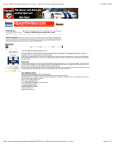
Auxiliary Power Unit Installation Guide
MODEL No. DPS6500
Step One
DP
READ BEFORE STARTING INSTALLATION
Each truck chassis is built differently and will require a different installation method.
Review the placement of ALL parts and components
before beginning the installation process.
DCP (Driver Control Panel)
Driver Control Panel
Condenser
120 VAC Receptacle Panel
HVAC
HVAC
CONDENSER
APU
APU
APU Parts and Components
Parts List:
APU
APU Installation Kit
Frame locks
_” x 6 _” Bolts
_” Split Lock Washers
_” lock nuts
Frame Washers
Fuel Pick-up Kit
Pick-up
Clamps
1
1
4
4
8
4
2
1
1
2
Exhaust Extension Kit
90 Degree exhaust pipe
Support bracket
Exhaust clamps
5/16” NC bolt
5/16” Washers
5/16” Lock Nuts
1
1
1
2
1
2
2
Fuel Supply
And Return
Battery Terminal Kit
Red heat shrink
Black heat shrink
Ring terminals
1
1
1
2
Cable ties
75
Condenser
Hoses
Mounting hardware
Harness
1
2
1
1
HVAC
Driver Control Panel
Power Outlet
1
1
1
Vehicle Fuel Tank
Parts and Tools Required
• Radiator hose – 3/4”
• Radiator shut off valves
• Radiator hose clamps
• An assortment of nuts, bolts, and
washers as required
• An assortment of electrical connectors
and protective conduit as required
• Heat shrink, pipe sealant, never seize,
electrical tape, expanding foam
• Torque wrench (100ft/lb)
• Hole saw kit (1”,1 _”, 3”, 3 _”, 4 _”)
• Portable lighting
• Hand forklift/lifting device
• Step drill
• Angle drill
• Reciprocating saw
• Nutsert ® installation tool
• Scale (refrigerant) accurate to ounces
• Gauges (refrigerant) 134A compatible
• Diamond Test Switch Module PG1008
• Flow Meter TK 9002
NOTE: The APU requires periodic maintenance. Ensure you have access to internal components (i.e. oil filter, air filter,
fuel filter and oil filter). The Diamond comes filled with long life coolant. Consult the truck owner prior to altering the vehicle in any way.
CAUTION: Trucks with longer chassis should have the APU mounted closer to the sleeper unit to avoid obstacles such as
railway crossings, speed bumps, curbs, etc. Before beginning installation of the Diamond system, disconnect the vehicle’s batteries.
If truck is equipped with a coolant valve, valve must be fully opened before starting APU.
Page1
Step Two
DP
MOUNTING THE APU
Installing
Back Plate OF APU Enclosure
1. Use existing holes at back of APU. Do not
drill new holes in the APU.
2. Torque mounting bolts to 100 ft/lbs.
3. Install exhaust pipe extension to APU; direct
exhaust away from vehicle.
Frame Gripper
Consider the Following:
• Free space around existing covers.
• Brackets for attaching covers, dryers,
fuel tanks, fasteners, existing plumbing
for air, fuel and water lines.
• Battery tray.
• Any hardware found in the mounting
location: move or modify if necessary.
Torque 100 ft/lb
Frame Rail
Frame Gripper Bolts
2 5/8” Minimum
Side Clearance
2 5/8” Minimum Side Clearance
11” Minimum Ground Clearance
WARNING: The APU is weighty. Do not drop it! Use a lifting device.
CAUTION: Do not mount the Diamond APU to bottom pan. Unit is designed to hang from chassis rails.
NOTE: Consult OEM frame drilling requirements if you are bolting APU directly to the trucks frame rail.
Page2
Step Three
DP
MOUNTING THE CONDENSER
Condenser Installation
Nutserts®
1. Select the site for the condenser on the rear or the vehicle sleeper.
2. Hold condenser in the preferred location and mark the holes clearly.
3. Drill holes 17/32” for Nutserts®.
4. Install the condenser assembly in the preferred location.
Blue Marking
Mounting Considerations
• The condenser must be installed on the back wall of the sleeper (outside).
Airflow around the condenser must not be blocked by headache racks, for
example.
• Install condenser within 8’ of the HVAC.
• The condenser must be installed vertically with the blue-marked side on the
bottom right (where the liquid refrigerant collects).
• Hose connection side of the condenser requires 5” free space to the nearest
obstruction to allow for hose connection.
• Keep the condenser out of the path of road spray.
• Refrigerant hoses must be clamped firmly.
• Do not allow Refrigerant hoses to touch each other; heat transfer will occur
and change the performance of the HVAC. Insulate or keep the hoses together.
3/8” NC Bolts
3 Per Side
Min 5” Clearance To
Allow For Hose
Connection
Condenser
Refrigerant
Hoses - Clamp
Securely
Condenser 12V
Power Harness
WARNING: If you are installing the
condenser to the back wall of the sleeper, use
large fender washers or a backing plate for extra
support.
Page3
NOTE: All hoses, cables, and
electrical wiring should be kept safe and
secured using split loom and cable ties
to prevent abrasion. Stay clear of exhaust
pipe and muffler.
HVAC
Step Four
DP
PLUMB THE APU TO THE MAIN ENGINE
Note: This APU Systems comes with a built in radiator. The connection below is optional.
Plumbing Procedure
1. Remove the truck radiator cap to free pressure from coolant system. Do not open when hot.
2. Deplete the truck coolant system (if necessary).
3. The APU is shipped with extensive life anti-freeze. Ensure this is compatible with truck coolant.
4. Ensure that the coolant will flow in the right direction (same direction whether the Diamond or main engine is running). The Diamond flow indicator
can be used to verify the flow.
5. Replenish the engine coolant in the system according to the specific engine manufacturer’s recommendations (additional coolant will be required).
Plumbing Considerations
• Silicon hose is satisfactory to use as coolant hose, but requires the use of silicon hose clamps.
• Ensure radiator coolant can always flow between truck engine and APU.
3/4” Fitting Return From APU
No Sharp Bends
1/2” Or Larger
NPT Fittings
Choose Ports That Are Far
Apart For Max Crossflow
High Pressure
Port
3/4” ID Hose
Loom All
Hoses
Low Pressure
Port (Suction)
3/4” Fitting
Supply To APU
Back View Of APU
Truck Engine
Install ShutOff Valves
Use A Flow Indicator To Comfirm
Flow Direction And Speed
WARNING: To avoid serious injury, permit the engine to cool before opening the radiator cap.
CAUTION: Plumbing through the dash or sleeper heater will null and void your warranty.
CAUTION: Take care not to spill coolant.
Page4
Step Five
DP
INSTALLING THE FUEL LINES
Installing The Stand Pipe
1. Locate hole in an area where the fuel pickup is kept safe (the center of the tank is recommended).
2. Tighten hose clamps.
3. Secure the fuel lines to reduce movement.
Tighten Until
Secure
Nut
Washer
Gasket
Tank
Flange
Cut Tube
Bottom 45°
Drill 1” Hole Using Unibit or Hole Saw
Supply 5/16” ID
Return 3/16” ID
12” Min Between
Supply And Return
Back View Of APU
No Kinks Or
Abrasion Points
Fuel Line
Gas Tank
WARNING: Exercise safety measures when working
Allow 1” To 2” Min.
Space To Bottom Of Tank
CAUTION: Keep fuel lines away from exhaust pipes and heated moving parts.
near flammable fuel.
CAUTION: The standpipe must enter the tank from the top and not the side.
CAUTION: Keep fuel lines safe from wear points.
Page5
Step Six
DP
ARRANGE BATTERY CABLES
Connecting To The Truck’s Battery
Strip 3/8”
Apply Heat To Shrink
Red Or Black Heat
Shrink Tubing
Positive Or Negative
Battery Cable
12 VDC Power
Supply Harness
Back View Of APU
APU-HVAC
Control Harness
Copper Lug
Using The Correct Crimping Tool Crimp
And Solder Copper Lug To Battery Cables
Negative (-Black)
Ground Cable
Ensure That the battery terminals are clean and free
of corrosion.
If not, remove and clean them.
Apply an dielectric grease to prevent corrosion.
Apply anti-corrosion paint over cable ends.
Teck Cable
Truck Batteries
Positive (+Red)
12 VDC Battery Cable
WARNING: Do not join the APU battery connections until the installation is complete and the APU is ready to test-start.
WARNING: Make sure the 120 VAC cable is connected to the installed CCU (if applicable). Terminate cable ends if no CCU is installed.
WARNING: Make sure that the polarity is correct before attaching battery leads. (The APU connects to 12VDC systems only).
Page6
Step Seven
DP
SYSTEM CHECK
Important: Perform these steps only after the HVAC and all other components have been installed.
System Check
• Oil level in the APU engine, add oil if necessary.
• Electrical and plumbing connections are secure.
• Radiator coolant valves (if any) fully open.
APU First Time Start Up
Before first time starting use the priming pump to clear the air in the fuel line.
Priming Pump
WARNING: Do not start or run the APU prior to purging the entire cooling system of air.
Failure to do so will result in APU engine failure.
WARNING: Do not operate the engine without the enclosure cover in place. Failure to do so may result in injury.
Completing the Installation
• Test all the functions of the APU and the HVAC.
• Replace vehicle access panels, fairings, interior components and hardware that was removed to facilitate the installation.
• Seal all holes made through the floor or walls of the truck bunk with suitable sealant such as expanding foam.
• Vacuum the interior of the cab/sleeper.
• Review the installation with the owner and instruct them on the proper operation of the Diamond Power Systems. Give the owner the Operator’s Manual.
• Complete all warranty cards and return to Diamond Power Systems.
Page7