1
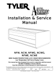
Installation & Service
Manual
RCCG shown with Riser Option 2
RCCG
REFRIGERATED CHEESE ISLAND MERCHANDISERS
Medium Temperature Self-Serve Display Cases
This manual has been designed to be used in conjunction with the
General (UL/NSF) Installation & Service Manual.
Save the Instructions in Both Manuals for Future Reference!!
This merchandiser conforms to the American National Standard Institute & NSF International Health and Sanitation standard ANSI/NSF 7 - 2003.
PRINTED IN Specifications subject to REPLACES
IN U.S.A.
change without notice. EDITION
4/05
ISSUE
DATE
10/07
Tyler Refrigeration * Niles, Michigan 49120
PART
NO.
9805000
REV.
B
RCCG
CONTENTS
Page
Specifications
RCCG Specification Sheets . . . . . . . . . . . . . . . . . . . . . . . . . . . . . . . . 4
Line Sizing Requirements . . . . . . (See General-UL/NSF I&S Manual)
Pre-Installation Responsibilities . . . . . (See General-UL/NSF I&S Manual)
Installation Procedures
Carpentry Procedures . . . . . . . . . . . . . . . . . . . . . . . . . . . . . . . . . . . 6
End Shelf Installation (RCCG w/Riser Opt. 2 or 3) . . . . . . . . . . . . . . 6
Trim Installation/Alignment . . . . . (See General-UL/NSF I&S Manual)
Plumbing Procedures . . . . . . . . (See General-UL/NSF I&S Manual)
Refrigeration Procedures . . . . . (See General-UL/NSF I&S Manual)
Electrical Procedures . . . . . . . . . . . . . . . . . . . . . . . . . . . . . . . . . . . . 6
Electrical Considerations . . . . . . . . . . . . . . . . . . . . . . . . . . . . . . . . . . 6
Defrost Information . . . . . . . . . . . . . . . . . . . . . . . . . . . . . . . . . . . . . 6
Defrost Control Chart . . . . . . . . . . . . . . . . . . . . . . . . . . . . . . . . . . . . 6
Installation Procedure Check Lists (See General-UL/NSF I&S Man.)
Wiring Diagrams . . . . . . . . . . . . . . . . . . . . . . . . . . . . . . . . . . . . . . . . . . . . 6
RCCG Domestic & Export (50 Hz) Case Circuits . . . . . . . . . . . . . . . 7
Cleaning and Sanitation . . . . . . . . . . . . (See General-UL/NSF I&S Manual)
Component Removal and Installation Instructions for Cleaning 10
Shelves and Shelf Brackets (RCCG w/Riser Opt. 2 or 3) . . . . . . . . 10
Screens . . . . . . . . . . . . . . . . . . . . . . . . . . . . . . . . . . . . . . . . . . . . . . 10
Bottom Trays . . . . . . . . . . . . . . . . . . . . . . . . . . . . . . . . . . . . . . . . . . 10
Perimeter Air Ducts . . . . . . . . . . . . . . . . . . . . . . . . . . . . . . . . . . . . . 10
Center Riser and End Duct Panels . . . . . . . . . . . . . . . . . . . . . . . . . 10
Curved Plexiglas Care . . . . . . . . . . . . . . . . . . . . . . . . . . . . . . . . . . 10
Page 2
October, 2007
Installation & Service Manual
RCCG
Page
General Information
NSF Product Thermometer Installation . . . . . . . . . . . . . . . . . . . . .11
Shelf and Shelf Bracket Adjustment . . . . . . . . . . . . . . . . . . . . . . 11
Service Instructions
Preventive Maintenance . . . . . . (See General-UL/NSF I&S Manual)
Ballast Replacement . . . . . . . . . . . . . . . . . . . . . . . . . . . . . . . . . . . 12
Anti-Sweat Replacement . . . . . . . . . . . . . . . . . . . . . . . . . . . . . . . . 13
Curved Plexiglas Replacement . . . . . . . . . . . . . . . . . . . . . . . . . . . 13
Plexiglas Finishing Procedure . . . . . . . . . . . . . . . . . . . . . . . . . . . . . 14
Parts Information
Operational Parts List . . . . . . . . . . . . . . . . . . . . . . . . . . . . . . . . . . 15
TYLER Warranty . . . . . . . . . . . . . . . . . (See General-UL/NSF I&S Manual)
The following Medium Temperature Cheese Island Merchandiser models are covered in
this manual:
MODEL
DESCRIPTION
RCCG
8’, 12’ AND 16’ CHEESE ISLAND MERCHANDISER WITH ONE
NON-REFRIGERATED CENTER SHELF
RCCG
(w/riser opt.1)
8’, 12’ AND 16’ CHEESE ISLAND MERCHANDISER WITH ONE
NON-REFRIGERATED CENTER SHELF AND ONE REFRIGERATED
WRAP-AROUND SHELF
RCCG
(w/riser opt.2)
8’, 12’ AND 16’ CHEESE ISLAND MERCHANDISER WITH ONE
NON-REFRIGERATED CENTER SHELF AND TWO REFRIGERATED
WRAP-AROUND SHELVES
October, 2007
Page 3
RCCG
SPECIFICATIONS
RCCG Refrigerated Cheese & Deli Island Merchandisers
Page 4
October, 2007
Installation & Service Manual
October, 2007
RCCG
Page 5
RCCG
INSTALLATION PROCEDURES
Fluorescent Lamp Circuit
Carpentry Procedures
All RCCG cases are supplied with T-8 lights
under both sides of the center riser top shelf.
The RCCG with riser option 1 comes with
one additional row of wrap-around T-8 shelf
lighting. The RCCG with riser option 2 comes
with two additional rows of wrap-around T-8
shelf lighting. All electronic ballasts are
remotely located under the center riser top
shelf. The lights are controlled by a light
switch under the center riser top shelf.
The RCCG models do not have any open
ends, therefore no pull-ups are required.
After all island cases have been positioned,
install the bottom trays and the case screens.
End Shelf Installation
(RCCG w/Riser Option 1 or 2)
Anti-Sweat Circuit
RCCG cases have one or two anti-sweat
heaters running around the inside edge of the
top shelf molding. These anti-sweat heaters
are wired directly to the main power supply
so they can operate at all times.
Defrost Information
See “General-UL/NSF I&S Manual” for
operational descriptions for each type of
defrost control.
End shelf assemblies may be shipped
separately. If they are not already installed,
remove end shelf assemblies from shipping
packaging. Align end shelf assemblies with
side shelves and attach two support brackets
to the reinforcement areas under each side
shelf. Secure the support brackets with
screws. After the end shelf support brackets
have been secured, the end shelves will be
supported by the side shelves.
Defrost
Defrost Defrosts Duration
Term.
Per Day
(Min)
Temp.
Type
RCCG w/ std riser or riser opt 1
Off Time
6
22
----RCCG w/ riser opt 2
Off Time
6
18
-----
Electrical Procedures
WIRING DIAGRAMS
Electrical Considerations
CAUTION
Make sure all electrical connections at
components and terminal blocks are tight.
This prevents burning of electrical terminals
and/or premature component failure.
Case Fan Circuit
This circuit is to be supplied by an uninterrupted, protected 120V circuit. The case fan circuit
is not cycled on any of these models.
Page 6
Defrost Control Chart
ELECTRICIAN NOTE - OVERCURRENT
PROTECTION
120V circuits should be protected by 15 or 20 Amp
devices per the requirements noted on the cabinet
nameplate or the National Electrical Code, Canadian
Electrical Code - Part 1, Section 28. 208V defrost
circuits employ No. 12 AWG field wire leads for field
connections. On remote cases intended for end to
end line-ups, bonding for ground may rely upon the
pull-up bolts.
The following wiring diagrams on pages 7
thru 9 will cover the RCCG case electrical
circuits, including optional configurations,
fans, lights and anti-sweats.
October, 2007
RCCG Domestic & Export (50 Hz) Case Circuits (8’ Case)
October, 2007
Page 7
RCCG Domestic & Export (50 Hz) Case Circuits (12’ Case)
Page 8
October, 2007
RCCG Domestic & Export (50 Hz) Case Circuits (16’ Case)
October, 2007
Page 9
RCCG
CLEANING AND SANITATION
Component Removal and Installation Instructions for Cleaning
Shelves and Shelf Brackets
(RCCG with Riser Option 1 or 2)
1. Remove product from shelves.
2. Unplug the light cords from the sockets in
the center riser duct panels.
3. Remove both end shelf assemblies. While
supporting end shelf assembly, remove
screws from end shelf support brackets
and side shelves. After screws are
removed, carefully pull out end shelf
assembly until support brackets clear the
ends of the side shelves. Remove the
end shelf assembly.
4. Push side shelves back and then lift up
and out to remove them from the shelf
brackets,
5. Remove side shelf brackets for slots in the
center riser uprights.
6. After cleaning, replace in reverse order.
Screens
1. Remove product from screens.
2. Push screens up until bottom screen tabs
clear the holes in the front duct.
3. Remove screens from holes in rear duct
panels and from case.
Center Riser and End Discharge
Duct Panels
1. Remove product, screens and bottom
trays, see this page.
2. Remove all mounting screws and center
riser and end discharge duct panels from
case.
3. After cleaning, replace in reverse order.
Curved Plexiglas Care
Cleaning
CAUTION
DO NOT use paper towels, soft clothes,
sponges or chamois to clean plexiglas.
These materials will scratch the acrylic
surface.
Clean with lukewarm water and plenty of
nonabrasive soap, or detergent. Use only
bare hand to dislodge any caked-on dirt.
Lightly dry with a clean damp chamois or
clean soft cloth.
Waxing
Wax should be applied in a thin even coat,
and brought to a high polish by rubbing
lightly with a dry clean soft cloth. Excessive
rubbing may cause scratching and/or buildup
an electrostatic charge, which attracts dust
and dirt to the surface. Electrostatic charge
can be removed by blotting acrylic surface
with a clean damp cloth.
4. After cleaning, replace in reverse order.
Bottom Trays
1. Remove product and screens from case.
See this page.
2. Grasp and lift out each of the bottom trays
from the case interior.
3. After cleaning, replace in reverse order.
Perimeter Air Ducts
Perimeter air ducts do not require removal for
cleaning. They are hinged and can be flipped
up for cleaning.
Page 10
October, 2007
Installation & Service Manual
GENERAL INFORMATION
NSF Product Thermometer
Installation
RCCG
Shelf and Shelf Bracket
Adjustment
1. Unwrap the thermometer and bracket
assembly shipped loose with the case.
2. Position bracket in front left corner of the
left-most bottom tray on one of the two
case sides. Making sure the bracket is
flush with the left edge, use the bracket
holes as a template for where to drill the
holes.
3. Drill two .196” holes in the bottom tray.
NOTE
For ease of installation, position the washers and capnuts on the top side of the
bracket and bottom tray.
1. Remove product from entire wrap-around
shelf that needs to be repositioned.
2. Unplug all shelf light cords that the shelf
light power.
3. Remove end shelf bracket support screws
from bottom end of side shelves.
4. Pull out end shelf assemblies until the
bracket supports clear the ends of the side
shelves. Remove the end shelf assemblies.
4. Mount the bracket to the bottom tray with
two screws, washers and capnuts.
5. Push side shelves back and then lift up
and out to remove them from the shelf
brackets.
6. Remove and reposition all the side shelf
brackets in the slots in the center riser
uprights.
7. Reassemble the wrap-around shelf in the
new position in the reverse order.
April, 2005
Page 11
RCCG
SERVICE INSTRUCTIONS
See “General-UL/NSF I&S Manual” for T-8
lamp and fan blade and motor replacement
instructions.
Ballast Replacement
WARNING
Shut off or disconnect power supply to
case before changing a ballast. 600V
electrical power from wire ends could
damage other components and/or cause
personal injury or death.
All ballasts for the center riser top shelf
lighting and the wrap-around shelf lighting
in riser options 1 & 2 are located under the
center riser top shelf behind the light fixtures.
See the diagrams below for ballast locations:
1. Remove screws and ballast covers from
behind the light fixtures under both sides
of the center riser top shelf.
NOTE
Mark wires before removing to assure
proper installation.
2. Disconnect wires from the faulty ballast.
Make note where the wires came from so
they can be reconnected the same way.
3. Remove mounting screws and the faulty
ballast.
4. Install new ballast and secure with mounting screws.
5. Reconnect wires to new ballast as they
were connected to the faulty ballast.
6. Install ballast covers under both sides of
the center riser top shelf and secure with
screws.
7. Reconnect power to the case and turn on
the light switch.
Page 12
October, 2007
Installation & Service Manual
Anti-Sweat Replacement
WARNING
RCCG
Perimeter Curved Plexiglas
Replacement
Shut off or disconnect power supply to
case before changing an anti-sweat.
Electrical power from wire ends could
damage other components and/or cause
personal injury or death.
Top Shelf Anti-Sweat
1. Remove the bumper (1), bumper retainer
(2) and top trim cladding (3) to expose
the bottom edge of the curved plexiglas
(4) and the mounting screws.
1. Disconnect faulty anti-sweat wire leads (1)
from case wires (2).
2. Remove aluminum tape and fualty antisweat wire (1) from inside lip of top shelf
(3).
3. Connect new anti-sweat wire leads (1) to
case wires (2).
4. Carefully position the new anti-sweat
wires (1) on inside lip of top shelf (3) and
secure in place with aluminum tape.
5. Reconnect the power to the case.
2. Remove mounting screws from broken or
damaged section of curved plexiglas (4).
Carefully cut apart sections of curved
plexiglass (4) at the joints. Remove
broken or damaged curved plexiglas (4).
NOTE
Make sure ends of adjoining plexiglas are
clean and dry.
3. Using a sanding block, sand all adjoining
edges of plexiglas to ensure, smooth
even edges.
April, 2005
Page 13
RCCG
4. Measure and cut replacement section of
curved plexiglas, if necessary, to approximately 1/4” longer than opening. Block
sand edges to make sure they are even
and smooth.
9. Apply acrylic
adhesive to 1/4”
acrylic dowel
pin and insert
the pin in top
hole. Let acrylic
adhesive dry for
5 minutes, then
cut off excess dowel pin and file smooth.
Plexiglas Finishing Procedure
5. Position and align new section of curved
plexiglas in the opening and carefully
hold it in place with padded clamps.
6. Using a 1/4” to 3/4” Unibit (step drill), drill
mounting holes in the same location as
the previously drilled holes were. Secure
new section with mounting screws.
CAUTION
Avoid cement touching clear plexiglas
surfaces. If contact occurs, the surface
will scar and the final appearance may
be unsatisfactory.
1. If joint seam of plexiglas does not match
perfectly, grind uneven seam with #36 grit
disc until seam is even. The finish area
should be approximately 4 inches wide.
2. Dry sand using #80 grit sand paper.
Increase width of finish area approximately 1/4” on each side.
3. Repeat step 2 using #280 grit sand paper.
4. Repeat step 2 using #400 grit sand paper.
5. Wet sand finish area using #800 grit sand
paper.
6. Repeat step 5 using #1000 grit sand
paper.
7. Using a downling fixture, align the top
edge of plexiglas joint seam. Carefully
apply acrylic adhesive (Weldon #1802) to
joint seam from the outside surface of the
plexiglas. Let adhesive dry for 5 minutes.
8. Using the same downling fixture, drill a
1/4” hole through the top of the plexiglas
joint seam. Remove the downling fixture.
7. Repeat step 5 using #1500 grit sand
paper.
8. Using a buffer,
apply Novus
brand heavy
scratch remover
#3 until smooth.
9. Repeat step 8
using Novus
brand fine scratch remover #2.
10. Polish the finish area using a clean soft
cloth and Novus brand Plastic Clean and
Shine #1.
Page 14
October, 2007
Installation & Service Manual
RCCG
PARTS INFORMATION
Operational Parts List
Case Usage
RCCG
(Std. Riser)
Domestic
RCCG
(Riser Opt 1)
Domestic
RCCG
(Riser Opt 2)
Domestic
Electrical Circuit
115 Volt 60 Hertz
115 Volt 60 Hertz
115 Volt 60 Hertz
Case Size
8’/12’/16’ Island
8’/12’/16’ Island
8’/12’/16’ Island
Fan Motor
5125532
5 Watt
5125532
5 Watt
5125532
5 Watt
Fan Motor Brackets
5213132
5213132
5213132
Fan Blades
(6.00” 20° 5B)(8’/12’/16’ Islands)
1657004
1657004
-----
-----
-----
9450091
Opt. ECM Fan Motor
9025002
8 Watt
9025002
8 Watt
9025002
8 Watt
Opt. ECM Fan Motor Brackets
5205279
5205279
5205279
Opt. ECM Fan Blades
(6.00” 15° 5B)(8’/12’/16’ Islands)
9408191
9408191
-----
-----
-----
9023766
9039652
9039652
9039652
12’ Island
9039650
9039650
9039650
16’ Island
9039636
9039636
9039636
T-8 Ballast (Center Riser Top Shelf)
8’ Islands (2-Lamp Ballast)
5991029
5991029
5991029
12’ Islands (4-Lamp Ballast)
5966635
5966635
5933365
16’ Island (3-Lamp Ballast)
5991030 (2)
5991030 (2)
5991030 (2)
T-8 Ballast (Riser Opt. Shelf Lights)
8’ Island (2-Lamp Ballast)
-----
5991029 (2)
-----
-----
-----
5966635 (2)
12’ Island (2-Lamp Ballast)
-----
5991029 (3)
-----
(4-Lamp Ballast)
-----
-----
5966635 (3)
16’ Island (2-Lamp Ballast)
-----
5991029 (4)
-----
(4-Lamp Ballast)
-----
-----
5966635 (4)
T-8 Lampholder (All Lamps)
9041897
9041897
9041897
NSF Product Thermometer
5967100
5967100
5967100
(6.00” 35° 5B)(8’/12’/16’ Islands)
(6.00” 30° 5B)(8’/12’/16’ Islands)
Anti-Sweat Heater (center top shelf)
8’ Island
(4-Lamp Ballast)
For information on operational parts not listed above contact the TYLER Service
Parts Department.
October, 2007
Page 15