1
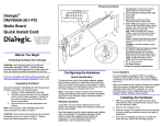
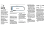
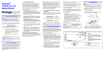
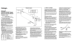
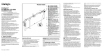
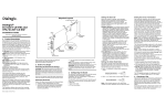
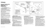
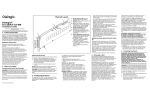
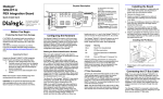
Physical Description
Dialogic
CH4 CH3 CH2 CH1
8
Red
Yellow
Green
Loopback
DM3 Fax Boards
DM/F300-1E1-PCIU
7
6
Quick Install Card
Part Number 64-0069-02
Copyright © 2001-2007
Dialogic Corporation.
All Rights Reserved.
9
5
10
Before You Begin
Protecting the Board from Damage
CAUTION: All computer boards are sensitive to
3
4
2
1
electrostatic discharge (“ESD”). Handle all staticsensitive boards and components at a static-safe work
area, and observe anti-static precautions at all times.
JP2A
JP2B
If you are not familiar with ESD safety precautions, visit
http://www.dialogic.com/support/hwinstall to learn more.
Unpacking the Board
Unpack the Dialogic® DM/F300-1E1-PCIU Fax Board
(“board”) according to the following steps:
1.
2.
3.
Prepare a static-safeguarded work area.
Carefully remove the board from the shipping
carton and anti-static packaging. Handle the
board by the edges and avoid touching the
board’s components.
Lay the board on the static-dissipative work
surface.
Note: Place boards in static-shielding bags when
carrying boards from station to station.
CAUTION: Do not remove the board from the anti-static
packaging until you are ready to install it. Observe
proper anti-static precautions at all times.
Configuring the Hardware
Board Identification
The device driver, part of the system software, assigns
board instance numbers in ascending order (beginning
with 0) as it detects each board in your system. A board
instance number is the identification (ID) number used by
the system software to recognize the board.
Note: If you add or remove a board, the system may
change the existing board instance numbers.
1. RJ-48C Jack: Connector to external digital
telephone network interface.
2. General Network Interface Alarm LED
3. Power LED
4. Reset LED
5. SW1: Rotary switch to set board identification
(Linux systems only).
6. Alarm LEDs: During power-up, indicate PowerOn Self-Test (POST) status. During operation
CH1 LEDs indicate network alarms for the
telephone trunk.
Red—Indicates loss of signal.
Yellow—Indicates loss of frame synchronization
at far end of external network.
Green—Indicates signal present; powered up
and receiving signal from external sources.
Loopback—Indicates loopback mode is
activated.
7. CT Bus/MVIP Bus Termination Jumpers:
Bus signal is terminated when the
corresponding jumper clip is installed.
Note: Signal must be terminated only on boards
at each end of the CT Bus cable.
JP2A: CT Bus termination jumper
JP2B: MVIP Bus termination jumper
8. P3: CT Bus connector
9. ISA Edge Retainer
10. Signal Processing Daughterboard
Linux Systems
In a Linux system, you must set SW1 to a unique
number for each installed board. Use a non-magnetic
screwdriver to turn SW1 to one of 16 board ID settings,
0–9 or A–F.
After the hardware and the system software are installed,
refer to the proper configuration files to retrieve the
assigned board instance ID number(s). For more
information about Linux configuration files, see the
Dialogic® System Software documentation.
Installing the Hardware
Windows Systems
Leave SW1 set to the factory default of 0 to let the
system automatically assign board instance numbers by
PCI bus slot number.
After the hardware and the system software are installed,
refer to the Dialogic® Configuration Manager (DCM)
utility to retrieve the assigned board instance ID
number(s). For more information about board
identification, see the DCM online help.
1. With your computer on the static-safe work area,
switch off the power and disconnect all power cords
from the electrical outlets.
2. Remove the computer cover.
3. Select an empty PCI expansion bus slot and remove
the slot’s retaining screw and access cover plate (if
applicable).
4. If you are not installing your board in an ISA form
factor PCI slot, remove the ISA edge retainer from
the board.
5. Using the slot’s board guides, insert the edge
connector of the board into the bus slot. Press firmly
until the board is securely seated in the slot.
Installing a PCI Board
Remove
Cover
Plate
PCI
Board
Computer
Chassis
PCI Slot
Note: Your system may include both CT Bus and SCbus
boards. To connect both board types, you must install a
CT Bus/SCbus Adapter on one of the CT Bus boards in a
system. See the CT Bus/SCbus Adapter Quick Install
Card for installation details about the Adapter and the
bus cables.
10. Install CT Bus Termination Jumpers only on boards
located at each end of the CT Bus cable. See the
“Physical Description” section for jumper details.
11. Replace the computer cover when finished and
reconnect the power cord.
12. Turn the computer’s power on.
local contact information. Dialogic also provides direct
support via Dialogic® Pro™ Services agreements. For
more details of direct support from Dialogic please refer
to: http://www.dialogic.com/support/DialogicPro.
CAUTION: If your BIOS is set to use Plug and Play
technology and there are ISA boards in your system, an
IRQ conflict can be created if a PCI Dialogic telecom
board is assigned the same IRQ as an ISA board. This
could cause the machine to stop responding. You can
prevent this by entering the BIOS and reserving the
appropriate IRQs (those used by your ISA boards) for
ISA use only.
If you have a sales question, please contact your
local Sales Representative or the Regional Sales Office
for your area. Address, telephone and fax numbers, are
available at the Dialogic website located at:
http://www.dialogic.com/contact.htm.
Returning a Product
To return a board for warranty repair or any other
returns, please refer to the following:
http://www.dialogic.com/support/hwfaults.
Sales Assistance
ISA Slot
6. Replace and tighten the retaining screw to secure the
board firmly in the chassis slot (if applicable).
7. Connect external digital telephone cable to the
RJ-48C jack on the board bracket.
RJ–48C Connectors
Pinouts for the RJ–48C
Jacks on Bracket
Network Interface
Cable Connector
1
2
3
4
5
6
7
8
1
2
3
4
5
6
7
8
After Installing the Hardware
Note: If you are adding hardware to an existing system,
you do not need to uninstall existing Dialogic® System
Software.
RCV_RING
RCV_TIP
CHASSIS GROUND
XMIT_RING
XMIT_TIP
CHASSIS GROUND
CHASSIS GROUND
CHASSIS GROUND
Pin 1
For a new installation, after installing the hardware
proceed with the system software installation as
described in the Dialogic System Software
documentation.
8. Repeat steps 3-7 for each additional board you are
installing.
9. Use the CT Bus cable to connect the board(s) you
are installing to other boards in the system. To
preserve the electrical integrity of the CT Bus, use a
CT Bus cable with the appropriate number of
connectors (“drops”). It is recommended that no more
than two connectors at either end of the cable be left
unused.
Installing the CT Bus Cable
Colored
Stripe
(Pin 1)
NOTE:
Your CT Bus cable may
have a different number
of connectors (drops).
CT Bus
Cable
For technical specifications and product information go
to: http://www.dialogic.com/products.htm.
Warranty and Return Information
Warranty Period
For specific warranty information for this board, refer to
the Warranty section of the Products page, located at
this URL: http://www.dialogic.com/warranties/.
Contacting Technical Support
Dialogic provides technical support for its products
through a network of value added distributors who are
trained to answer technical questions on installing and
®
configuring Dialogic products. If you are unsure how to
contact your support channel, please call Dialogic in the
United States at 973-967-6600 (9am-5pm EST) and we
will assist in obtaining the appropriate support channel.
Outside the United States please refer to
http://www.dialogic.com/support/contact to obtain
To purchase Dialogic® products, please refer to the
following website to locate the appropriate supplier:
http://www.dialogic.com/purchase.htm.
All contents of this document are furnished for informational use only and are subject to change without notice
and do not represent a commitment on the part of Dialogic Corporation or its subsidiaries (“Dialogic”).
Reasonable effort is made to ensure the accuracy of the information contained in the document. However,
Dialogic does not warrant the accuracy of this information and cannot accept responsibility for errors,
inaccuracies or omissions that may be contained in this document.
®
INFORMATION IN THIS DOCUMENT IS PROVIDED IN CONNECTION WITH DIALOGIC PRODUCTS.
NO LICENSE, EXPRESS OR IMPLIED, BY ESTOPPEL OR OTHERWISE, TO ANY INTELLECTUAL
PROPERTY RIGHTS IS GRANTED BY THIS DOCUMENT. EXCEPT AS PROVIDED IN A SIGNED
AGREEMENT BETWEEN YOU AND DIALOGIC, DIALOGIC ASSUMES NO LIABILITY WHATSOEVER,
AND DIALOGIC DISCLAIMS ANY EXPRESS OR IMPLIED WARRANTY, RELATING TO SALE AND/OR
USE OF DIALOGIC PRODUCTS INCLUDING LIABILITY OR WARRANTIES RELATING TO FITNESS
FOR A PARTICULAR PURPOSE, MERCHANTABILITY, OR INFRINGEMENT OF ANY INTELLECTUAL
PROPERTY RIGHT OF A THIRD PARTY.
Dialogic products are not intended for use in medical, life saving, life sustaining, critical control or safety
systems, or in nuclear facility applications.
It is possible that the use or implementation of any one of the concepts, applications, or ideas described in this
document, in marketing collateral produced by or on web pages maintained by Dialogic may infringe one or more
patents or other intellectual property rights owned by third parties. Dialogic does not provide any intellectual
property licenses with the sale of Dialogic products other than a license to use such product in accordance with
intellectual property owned or validly licensed by Dialogic and no such licenses are provided except pursuant to a
signed agreement with Dialogic. More detailed information about such intellectual property is available from
th
Dialogic’s legal department at 9800 Cavendish Blvd., 5 Floor, Montreal, Quebec, Canada H4M 2V9. Dialogic
encourages all users of its products to procure all necessary intellectual property licenses required to
implement any concepts or applications and does not condone or encourage any intellectual property
infringement and disclaims any responsibility related thereto. These intellectual property licenses may
differ from country to country and it is the responsibility of those who develop the concepts or applications
to be aware of and comply with different national license requirements.
Dialogic, Diva, Eicon, Eicon Networks, Eiconcard, Dialogic Pro and SIPcontrol, among others, are either
registered trademarks or trademarks of Dialogic. Dialogic's trademarks may be used publicly only with permission
from Dialogic. Such permission may only be granted by Dialogic’s legal department at 9800 Cavendish Blvd., 5th
Floor, Montreal, Quebec, Canada H4M 2V9. Any authorized use of Dialogic's trademarks will be subject to full
respect of the trademark guidelines published by Dialogic from time to time and any use of Dialogic’s trademarks
requires proper acknowledgement. The names of actual companies and products mentioned herein are the
trademarks of their respective owners.