1
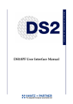
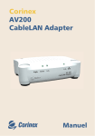
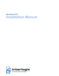
#2%!4%!,)'(4.).'&!34(/-%.%47/2+).-).54%3
AP
Manual
Corinex AV200 Powerline Ethernet Wall Mount
Corinex Communications Corp.
# 601 - 905 West Pender Street
Vancouver, BC
V6C 1L6, Canada
EN 61000-3-2
EN 61000-3-3
Vancouver / April 14. 2008
Copyright
This document, as well as the software described in it, is furnished under license and
may be used or copied only in accordance with the terms of the license. The content
of this document is furnished for informational use only, it is subject to change without
notice, and it does not represent a commitment on the part of Corinex Communications
Corp.
Corinex Communications Corp. assumes no responsibility or liability for any errors or
inaccuracies that may appear in this document.
It is our policy to enhance our products as new technologies, hardware components,
software and firmware become available; therefore, the information contained in this
document is subject to change without notice.
Some features, functions, and operations described in this document may not be included
and sold in certain countries due to government regulations or marketing policies.
The use of the product or its features described in this document may be restricted or
regulated by law in some countries. If you are unsure which restrictions or regulations
apply, you should consult your regional Corinex office or the authorized reseller.
Published by:
Corinex Communications Corp.
601 - 905 West Pender Street
Vancouver, BC V6C 1L6
Canada
Tel.: +1 604 692 0520
Fax: +1 604 694 0061
1
Corinex is a registered trademark of Corinex Communications Corp.
Microsoft, MS-DOS, MS, Windows are either registered trademarks or trademarks of
Microsoft Corporation in the U.S.A. and/or other countries.
All products or company names mentioned herein may be the trademarks of their
respective owners.
Copyright (c) 2001-2008 by Corinex Communications Corp.
NOTE: This equipment has been tested and found to comply with the limits for
Class B information technology equipment. These limits are designed to provide
reasonable protection against harmful interference in a residential installation.
This equipment generates, uses and can radiate radio frequency energy and, if
not installed and used in accordance with the instructions, may cause harmful
interference to radio communications. However, there is no guarantee that interference will not occur in a particular installation. If this equipment does cause
harmful interference, the end user is advised to take adequate measures.
2008-04-14 ver. 1
Corinex AV200 Powerline Ethernet Wall Mount
End User License Agreement
CORINEX COMMUNICATIONS CORPORATION
This End User License Agreement (“EULA”) is a legal agreement between you and CORINEX
COMMUNICATIONS CORPORATION (“CORINEX”) with regard to the copyrighted Software
provided with this EULA.
Use of any software and related documentation (“Software”) provided with a CORINEX hardware
product, or made available to you by CORINEX via download or otherwise, in whatever form or media,
will constitute your acceptance of these terms, unless separate terms are provided by the software
supplier, in which case certain additional or different terms may apply. If you do not agree with the terms
of this EULA, do not download, install, copy or use the Software.
1. Licence Grant. CORINEX grants to you a personal, non-transferable and non-exclusive right to use
the copy of the Software provided with this EULA. You agree you will not copy the Software except
as necessary to use it on a single hardware product system. You agree that you may not copy the
written materials accompanying the Software. Modifying, translating, renting, copying, transferring
or assigning all or part of the Software, or any rights granted hereunder, to any other persons, and
removing any proprietary notices, labels or marks from the Software is strictly prohibited. Furthermore,
you hereby agree not to create derivative works based on the Software. You may permanently transfer
all of your rights under this EULA, provided you retain no copies, you transfer all of the Software, and
the recipient agrees to the terms of this EULA. If the Software is an upgrade, any transfer must include
all prior versions of the Software.
2. Copyright. The Software is licensed, not sold. You acknowledge that no title to the intellectual property
in the Software is transferred to you. You further acknowledge that title and full ownership rights to
the Software will remain the exclusive property of Corinex Communications Corporation and/or its
suppliers, and you will not acquire any rights to the Software, except as expressly set forth above. All
copies of the Software will contain the same proprietary notices as contained in or on the Software.
3. Reverse Engineering. You agree that you will not attempt, and if you are a corporation, you will use
your best efforts to prevent your employees and contractors from attempting to reverse compile,
modify, translate or disassemble the Software in whole or in part. Any failure to comply with the above
or any other terms and conditions contained herein will result in the automatic termination of this
license and the reversion of the rights granted hereunder to CORINEX.
4. Disclaimer of Warranty. The Software is provided “AS IS“ without warranty of any kind. CORINEX
and its suppliers disclaim and make no express or implied warranties and specifically disclaim warranties
of merchantability, fitness for a particular purpose and non-infringement of third-party rights. The
entire risk as to the quality and performance of the Software is with you. Neither CORINEX nor its
suppliers warrant that the functions contained in the Software will meet your requirements or that the
operation of the Software will be uninterrupted or error-free.
5. Limitation of Liability. Corinex’s entire liability and your exclusive remedy under this EULA shall not
exceed the price paid for the Software, if any. In no event shall CORINEX or its suppliers be liable to
you for any consequential, special, incidental or indirect damages of any kind arising out of the use or
inability to use the software, even if CORINEX or its supplier has been advised of the possibility of such
damages, or any claim by a third party.
6. Applicable Laws. This EULA will be governed by the laws of Canada, excluding its conflict of law
provisions.
Corinex AV200 Powerline Ethernet Wall Mount
2
End User License Agreement
7. Export Laws. This EULA involves products and/or technical data that may be controlled under any
applicable export control laws, and regulation, and may be subject to any approval required under such
laws and regulations.
8. Precedence. Except as set out above, where separate terms are provided by the software supplier,
then, subject to this EULA, those terms also apply and prevail, to the extent of any inconsistency with
this EULA.
REGISTRATION AND WARRANTY
Please see the included product registration card for details of the standard consumer warranty on this
fine Corinex product.
3
Corinex AV200 Powerline Ethernet Wall Mount
Contents
Contents
1.
1.1
1.2
2.
2.1
2.2
2.3
2.4
2.5
2.6
3.
3.1
3.2
3.3
3.4
3.5
4.
4.1
4.2
5.
5.1
5.2
5.3
5.4
6.
Copyright .......................................................................................... 1
End User License Agreement .............................................................. 2
Introduction ..................................................................................... 5
Overview ........................................................................................... 5
About this manual ............................................................................ 5
Installation ........................................................................................ 6
Package Contents ............................................................................ 6
System Requirements ........................................................................ 6
Physical Description ........................................................................ 6
Functional Description ...................................................................... 7
Technical specifications ................................................................... 11
Connecting the Wall Mount Adapter ............................................. 11
Adapter Configuration .................................................................... 12
Password Page ................................................................................. 12
Main Page ....................................................................................... 12
Additional Information Page........................................................... 14
Change Configuration Page ........................................................... 17
Firmware Update Page .................................................................. 30
Video Network Setups ................................................................... 31
Introduction ................................................................................... 31
Network Scenarios ......................................................................... 31
Network Configuration .................................................................. 35
Setting an IP Address on your Computer .......................................... 35
Improving Network Performance ................................................... 44
Checking Network Performance ..................................................... 45
Using Powerline Noise Filters ......................................................... 45
Troubleshooting Guide .................................................................. 47
Corinex AV200 Powerline Ethernet Wall Mount
4
Introduction
1 Introduction
1.1 Overview
The Corinex AV200 Powerline Ethernet Wall Mount Adapter is a network adapter,
connecting your computers and devices to each other, and to your Internet
connection, over the electrical circuits already in your home or office. Just plug
the wall mount adapters into the wall, connect them to your computers, and you
have an instant computer network, running at industry-leading speeds of up to 200
Mbps!
The advantages of Powerline include low network maintenance costs and no
installation of long network cables. Corinex AV200 Powerline networks are simple
to set up and instantly provide network connections at every standard electrical
outlet.
The Corinex AV200 Powerline Ethernet Wall Mount:
• Enables users to connect individual PCs or other Ethernet devices to a local
area network through existing electric power lines (Powerline).
• Enables file- and application-sharing.
• Enables peripheral- and printer sharing.
• Enables shared broadband Internet access.
• Enables sharing of bandwidth for multimedia applications, including voice, data,
audio and video.
• Eliminates the need for long network cables throughout your home or office
• Provides a real, cost-effective, and reliable solution for high-speed
communications in any home or small office.
• Provides a one-touch button security configuration and synchronization.
• Provides an energy-saving standby mode.
• Provides a multi-colored Video Performance Indicator.
1.2 About this Manual
This User Guide includes everything you need to know to help you successfully
install the Corinex AV200 Powerline Ethernet Wall Mount and meet your networking
needs. With the information in this manual, you should be able to:
• Plan the configuration of your Corinex AV200 Powerline network.
• Install and configure your Corinex AV200 Powerline Ethernet Wall Mount
according to your plan
• Verify and optimize the performance of your Corinex AV200 Powerline
Ethernet Wall Mount
Corinex AV200 Powerline Ethernet Wall Mount
5
Installation
2 Installation
2.1 Package Contents
When you receive your Corinex AV200 Powerline Ethernet Wall Mount, check to be
sure that your package contains:
• Corinex AV200 Powerline Ethernet Wall Mount(2x for Dual Pack)
• Standard Ethernet cable (2x for Dual Pack)
• CD with documentation
• Quick Start Guide
• Registration and Warranty Card
We are always working to improve our products. For any hardware/software
changes, downloads, and additional information on your device, please visit
www.corinex.com/retail.
2.2
•
•
•
•
2.3
System Requirements
IBM compatible PC or a Macintosh
One available 10/100 Mbps Ethernet port
Windows 98/ME/2000/NT/XP, Mac OS X or Linux operating system
Javascript-compatible web browser for configuration (Netscape, Internet
Explorer, Opera…)
Physical Description
Button Definitions
(Buttons from top to bottom)
1. STANDBY
a. Implements the energy-saving Standby
Mode of operation when the device
is not in active use.
2. SYNC/ RST
a. Implements the one-button security
configuration and synchronization.
b. Can also be used to perform a Factory
Reset on the device.
STANDBY
SYNC/RST
Power
VPI
AV200
Powerline
Wall Mount
AP
Corinex AV200 Powerline Ethernet Wall Mount
6
Installation
LED Definitions
(Buttons from top to bottom)
1. PWR (Upper LED)
Shows the status of the adapter: the LED is on, if the adapter is connected to
power.
2. VPI (Middle LED)
Displays the quality of the powerline link, when the adapter is synchronized with
another adapter on the same network.
3. AP (Lower LED)
Displays the adapter type (its role in the network). If the LED is on, adapter is
Fixed AP (Access point), if the LED is off, adapter is EP (End point).
Connector Definitions
1. LAN: 1x RJ-45 LAN10/100 Ethernet port
7
ND
STA
BY
00 e
AV2 erlin nt
Pow ll Mou
Wa
ST
C/R
SYN
Pow
er
VPI
AP
2.4
Functional Description
2.4.1 Standby Button
By default, when plugged in, the adapter is in the ON state. When Standby operation
is desired, the button should be pressed and released at once. This will set the
adapter in energy-saving Standby operation mode. When the adapter is in Standby
operation, the button can be pressed to set the adapter back into the ON mode.
Corinex AV200 Powerline Ethernet Wall Mount
Installation
2.4.2 SYNC/ RST Buttton
2.4.2.1 OBUS
By default, Corinex AV200 Ethernet Wall Mount powerline adapters come without
a network identifier and encryption key. As a result, when they are plugged into the
mains a new PLC network will be created (called public network). It will operate
smoothly, but without security configuration. In other words, any nearby Corinex
AV200 Ethernet Wall Mount powerline adapters (wanted or unwanted) without
network ID and encryption key, connected to the same electrical grid, will become
part of this PLC network. That is why it is recommended to configure a specific
private PLC network (with a unique network identifier and encryption key) for
guarantying the security of the home network.
Configuring a private powerline network
It is recommended to choose as Fixed AP the adapter that will be connected to the
ISP broadband connection (i.e. DSL router, cable modem, etc.), if any, or to the data
or media source device (i.e. Media Center PC, etc.). Only one Fixed AP must exist
in the network. To configure a private powerline network, perform the following
steps:
1. The first step is to configure the Fixed AP adapter. Press the “SYNC/RST”
button for around two seconds until the AP indicator starts blinking to configure
the selected adapter as a Fixed AP. Special Network ID and Encryption Key will be
generated automatically and auto-configured. The AP indicator LED of the
adapter will be solid green after the process finishes;
2. To add one or more EPs to the network, press the “SYNC/RST” button again in
the AP adapter until its AP indicator starts blinking in order to open a configuration
period (around 30 seconds);
3. During the configuration period of the AP adapter you must press the “SYNC/
RST” buttons for two seconds in the EP adapters until their AP indicator starts
blinking;
4. All the adapters complete the configuration process successfully when their AP
indicator flashes three times during 0.5 seconds and they return to normal
operation mode as EPs (their AP indicator will remain OFF). The only AP indicator
that must remain ON is that of the Fixed AP adapter;
5. If there is more than one AP device or if there is no AP device, factory reset is
required (see Section 5).
Adding new powerline adapters to an existing private powerline network
To add additional powerline devices to an existing network, perform the following
steps:
Corinex AV200 Powerline Ethernet Wall Mount
8
Installation
1. Identify which is the AP adapter in an existing PLC network. The AP adapter
always shows its AP indicator ON in green. The other adapters are EPs and their
AP indicators will be OFF;
2. Next, press “SYNC/RST” button for around two seconds on the AP adapter until
its AP indicator starts blinking. This opens a configuration period of 30 seconds;
3. During this configuration period, press the “SYNC/RST” button on the new EP
adapter(s) until their AP indicator starts blinking, then release the button.
Exchanging of Network ID and Encryption Key between AP and new EPs is done
automatically. All the new adapters and the AP device finish their configuration
process successfully when their AP indicator flashes three times during 0.5
seconds. All adapters then return to normal operation mode belonging to the
same powerline network.
Note:
1. The adapters during the configuration process shall be within close
proximity such that they are able to communicate with each other without
a network identifier and an encryption key.
2. When adding adapters to the network, the button of the second adapter
should be pressed only after the button of the first adapter has been
released.
2.4.2.2 Factory Reset
Perform the following steps to do a factory reset:
1. Press the adapter’s “SYNC/ RST” button for at least ten seconds (its lower
LED will start blinking in green once the button has been pressed for two
seconds, and will keep blinking for about eight seconds). When the VPI LED
switches OFF, release the button.
2. After five seconds, the VPI LED will switch ON again.
3. At this time, the adapter resets its configuration to the factory default settings
and automatically restarts
The significant factory settings in the AV200 Wall Mount are presented below:
• Default IP is 10.10.1.69
• Default configuration password is “paterna”
• Default factory reset password is “betera”
• Default network ID is the public network ID
• Default Encryption Key is none.
Corinex AV200 Powerline Ethernet Wall Mount
9
Installation
2.4.3 LED Definitions
2.4.3.1 VPI LED
VPI
Colour
Adapter Status
Low Red
OFF (Standby)
Meaning
Red
ON
If Powerline link, Estimated application
Throughput < Low Threshold
Orange
ON
If Powerline link, Low Threshold < Estimated application Throughput < High
Threshold
Green
ON
If Powerline link, Estimated applicationThroughput > High Threshold
Blinking
ON
Adapter has Ethernet link activity
Adapter is in Standby mode
The low and high throughput thresholds are default to be 6 Mbps and 12 Mbps
respectively, and can be redefined by users through the web interface.
2.4.3.2 AP LED
10
When the adapter is configured as Fixed AP, the LED will be on. When the adapter
is configured as EP, the LED will be off.
Corinex AV200 Powerline Ethernet Wall Mount
Installation
2.5
Technical Specifications
Standards Compliance
IEEE 802.3u
Speed
Up to 200 Mbps on physical layer
AC Plug Type
US, EU, UK and AUS
LED Status Lights
PWR, VPI, AP
Schnittstellen
10/100BaseT Fast Ethernet, Powerline
BenutzterFrequenzbereich
2 – 34 MHz
Eingangsleistung
85 to 265 V AC, 50/60 Hz
Abmessungen
107 mm L x 72 mm B x 79 mm H
Übertragene Stromspektrumdichte -56 dBm/Hz
Stromverbrauch
5W
Sicherheit & EMI
UL/EN 60950, FCC Teil 15, EN 55022
EMC Limits
11
2.6
Connecting the Wall Mount Adapter
To connect the Corinex AV200 Powerline Ethernet Wall Mount to your computer,
follow the steps listed below.
1. Once the security configuration and synchronization have been completed
the adapters may be unplugged and taken to the respective places in the home
where the computers will be connected to them.
2. Connect the supplied Ethernet cable to the Ethernet (LAN) port on the wall
mount, and to an Ethernet port on your computer.
3. Plug the Corinex AV200 Powerline Ethernet Wall Mount unit directly
into any standard electrical outlet.
Note: The Corinex AV200 Powerline Ethernet Wall Mount should be plugged
directly into a wall outlet, not into a power strip or surge suppressor. Power
strips and surge suppressors can weaken or block the Powerline network
signal.
Corinex AV200 Powerline Ethernet Wall Mount
Adapter Configuration
3 Adapter Configuration
In order to access the web-based configuration pages, it is necessary to know the
adapter’s IP address and for your computer to be connected to the wall mount
adapter (as described in section 2.6). Corinex adapters come with a default IP
address 10.10.1.69.
Open a web browser (Microsoft Internet Explorer v6.0, Mozilla v1.7.2 and Mozilla
Firefox v1.0 have been verified for use with these products.), and type the IP address
in the address bar – the URL should be http://10.10.1.69/ unless you have already
changed it to something else.
Changing the default IP address is required, so that two or more devices can be on
the same network. The IP address is a device’s unique identifier on a network, so
the adapters would not be able to tell each other apart if they had the same identity,
just as a postman wouldn’t know which house to deliver to, if two neighbors in a
large city had the same street number. Follow the steps below to configure a new
IP address for each adapter:
1. In your computer’s network settings, enter an address in the range 10.10.
X.X (e.g. 10.10.1.2) and set the netmask to 255.255.0.0. This is necessary in
order to be compatible with the adapter’s default settings. For details on how
to set up an IP address on your computer, please see chapter 5.
2. Plug in your Corinex AV200 Powerline Ethernet Wall Mount Adapter and connect
it to the PC via the supplied Ethernet cable.
3. Open your web browser and type http://10.10.1.69. You will then be able to
configure the settings for your wall mount adapter.
3.1 Password Page
If the password is enabled, you’ll need to login before you can access the configuration
pages. Therefore, you will first be taken to the Authentication page for login. If
the configuration page is left idle for 5 minutes, the login expires and you will need
to login again.
Note: The default password is “paterna”.
Corinex AV200 Powerline Ethernet Wall Mount
12
Adapter Configuration
Note: If password protection is disabled, you will be taken straight to the
Main page, rather than the Authentication page.
3.2 Main Page
This is the first page after login. It shows basic status information about the adapter,
a list of available Powerline connections, MAC and IP addresses, MAC type, etc.
At the top of the screen are the main categories, “Status,”
“Additional Information,” “Basic Settings” and “Advanced Settings”. The
menu shows the current category and page. (The current category is shown in black
text and does nothing when clicked.)
Corinex AV200 Powerline Ethernet Wall Mount
13
Adapter Configuration
3.3 Additional Information Page
This page shows more detailed information about the adapter.
System Information
Uptime
Shows how long the adapter has been
running since the last startup.
Firmware Version
Shows the detailed firmware version.
MAC Status
MAC Address
Displays the unique hardware address
(serial number) of the adapter.
MAC Type
This should be In-Home AV.
Node Type
Shows the type of device – this can
be EP, AP or Fixed AP. For more
information about these types, please
see section 3.4.3.1.
Network Identifier
Shows the Network Identifier. Only
devices with the same Network
Identifier can communicate with each
other.
Encryption Key
Shows whether or not the network
encryption is enabled.
Network Status
IP Configuration
Shows “Fixed” for set static IP
addresses, or “DHCP” if the device
receives an address from the server.
IP Address
Shows the current IP Address of the
adapter.
Subnet Mask
Shows the subnet mask.
Default Gateway IP Address
Shows the Default Gateway.
Corinex AV200 Powerline Ethernet Wall Mount
14
Adapter Configuration
PHY Status
Notches
Indicates whether or not frequency
notches are enabled. notches should
always be enabled, in order to eliminate
interference with Radio Amateur bands
specified by the local authorities.
Power Control
Indicates status of the power control
mechanism (described in chapter
3.4.4).
Multicast Status
IGMP Aware Multicast Syndication
Shows the status of the IGMP settings
(described in chapter 3.4.5).
Multicast Bindings
Shows all multicast bindings between
multicast IP Addresses and AV200
Powerline MAC addresses.
15
VLAN Status
VLAN Configuration
Indicates whether or not VLAN (virtual
networking) is enabled.
VLAN Tag
Shows the selected VLAN Tag. All traffic
from the ethernet port carries this tag.
VLAN Priority
Shows the selected priority, which is
inserted into the VLAN tag.
Corinex AV200 Powerline Ethernet Wall Mount
Adapter Configuration
Priority Status
Default Priority
Shows the default priority for traffic
transmission.
Criterion 1 & 2
Shows which criteria are used to classify
traffic. This can be TOS, 802.1p or
Custom. If Custom, the complete
parameters are displayed below.
Please see chapter 3.4.7 for additional
information.
Security Status
Status
Indicates whether
configuration page
protected.
or
is
not the
password
You can leave the configuration page anytime by clicking on fhe “Log out” button in
the upper right corner of the screen.
Corinex AV200 Powerline Ethernet Wall Mount
16
Adapter Configuration
3.4 Change Configuration Page
3.4.1 Overview
The configuration pages allow you to change the settings on the wall mount adapter.
Any parameters changed here will be stored in the wall mount adapter‘s permanent
memory, and at the next startup, will be activated automatically. Any changes will take
effect immediately after startup, with the exception of the Network Configuration
settings (these require a restart of the wall mount adapter).
The configuration is divided into two sections: “Basic settings” and “Advanced
settings.”
17
Notes :
• A different IP must be set for each adapter on the network. The adapter’s
IP does not need to be in the same range as the PC, except when trying to
change the adapter’s settings on the configuration page (10.10.X.X and netmask
255.255.0.0 for an adapter with the default factory settings).
• The adapter’s netmask can also be changed, for example to a type C
(255.255.255.0) if necessary. This is a more advanced option, which you may
ignore if you’re not familiar with it.
Corinex AV200 Powerline Ethernet Wall Mount
Adapter Configuration
• If the wall mount adapter is to be accessed through a router (e.g., in a large office
network), the gateway IP needs to be configured. Otherwise, it can be ignored.
WARNING: CHANGING AN ADAPTER‘S IP TAKES EFFECT ONLY
AFTER A RESTART. YOU MAY WANT TO PLACE A LABEL ON EACH
ADAPTER WITH ITS IP ADDRESS, SO YOU DON’T ACCIDENTALLY
LOSE THE ABILITY TO ACCESS IT.
3.4.2
Basic Settings
Most of the time, the only thing that needs to be changed is the Network Identifier
and the Encryption, in order to avoid interfering with other networks and protect
your information. Most people will not need to enter the Advanced settings section.
The AV200 Powerline network is totally secure with these basic settings.
18
The AV200 technology supports multiple networks on a single circuit. The networks
are differentiated by Network Identifiers, which can be set in this section. The
Network Identifier is a string of characters (Network Identifier field) which simply
acts as a name for the network. This Network ID must be identical for all adapters
on a network. Adapters with different Network IDs will not be able to communicate
with each other.
The Network Identifier string can have up to 20 ASCII characters (lettters and
numbers). Quote and double-quote characters are not supported. Extended ASCII
characters are not recommended.
Corinex AV200 Powerline Ethernet Wall Mount
Adapter Configuration
If you want to enable 3DES encryption in your network, please select one of the
input methods and enter the password.
Input methods:
ASCII
If ASCII is selected, the Encryption Key
string can have up to 24 non-extended
ASCII characters. Quote and doublequote characters are not supported.
Extended ASCII characters are not
supported.
HEX
On the other hand, if HEX mode is
selected, the Encryption Key string can
have up to 42 hexadecimal digits (for
example 34AE4F54B38D). This HEX
method is more secure than ASCII.
The Corinex AV200 Wall Mount Adapter supports also the stronger AES encryption.
In order to enable it, please select AES from the menu and enter the password.
Note: If you decide to use the AES encryption, please make sure all powerline
adapters in your network are capable of using this type of encryption and it
is enabled on all devices. If some devices are not capable of AES encryption,
and it is turned on, communication will not be possible between the devices
with AES encryption and devices without it.
3.4.3 Advanced Configuration
The advanced configuration section is divided into several subsections, which are
described here.
3.4.3.1 MAC Configuration
The following parameters relate to the physical network setup, or topology. The
current firmware version (Spirit 4.2.68 at the time of this publication) supports only
one topology: In-Home AV. In this In-Home AV topology, two different adapter
types can be configured, setting an adapter to function as either an Automatic
EP/AP (End Point or Access Point, depending on the other adapters in the network)
or a Fixed AP (assigned Access Point). Section 4 (In-Home AV Network Topology)
contains more information about the available network topologies.
Corinex AV200 Powerline Ethernet Wall Mount
19
Adapter Configuration
If you want to configure the wall mount adapter to function as an automatic EP/AP,
please select “EP” from the list. If you want the adapter to behave as a Master,
select “Fixed AP” from the list. After selecting one, click “OK” to confirm your
choice.
Note: Fixed AP is available only when a Network ID is set on the adapter
(please read below for details on Network Identifiers).
The AV200 technology supports multiple networks on a single circuit. The networks
are differentiated by Network Identifiers, which can be set in this section. The
Network Identifier is a string of characters (Network Identifier field) which simply
acts as a name for the network. This Network ID must be identical for all adapters
on a network. Adapters with different Network IDs will not be able to communicate
with each other.
Note: Please refer to section 4.2 for more information about the network
types and their Network Identifiers.
If the Network Identifier field is left blank, the default, publicly available network is
configured, and the adapter can communicate with all other adapters with empty
Network Identifier fields. When you enter a Network ID, a private network is
configured.
Note: The Network Identifier string can have up to 20 ASCII characters.
Quote and double-quote characters are not supported. Extended ASCII
characters are not recommended
Corinex AV200 Powerline Ethernet Wall Mount
20
Adapter Configuration
The following picture shows an example of two AV200 networks with different
Network Identifiers:
Modem
Modem
Network Id:
Home
Modem
Modem
Network Id:
Other
Communication between adapters (called modems in this picture) is encrypted with
a Triple-DES algorithm. The Encryption Key can be set to any string of letters and
numbers (Encryption Key field, ASCII or HEX). Saving an empty string (leaving it
blank) disables the encryption. After selecting ASCII or HEX and then entering a
password, click “OK” to confirm your choice.
Note: The encryption will be enabled only if a non-empty Network Identifier
is set.
Note: If ASCII is selected, the Encryption Key string can have up to 24
non-standard ASCII characters. Quote and double-quote characters are not
supported. Extended ASCII characters are not supported.
On the other hand, if HEX mode is selected, the Encryption Key string can
have up to 42 hexadecimal digits (for example 34AE4F54B38D). HEX strings
generate stronger keys.
Corinex AV200 Powerline Ethernet Wall Mount
21
Adapter Configuration
3.4.3.2 Network Configuration
Your Corinex AV200 Powerline Wall Mount can be configured to use either DHCP
(automatic IP address assignment), or a fixed IP.
The following parameters are used by the fixed IP configuration. In order for the wall
mount adapter to correctly communicate with other devices on the network, it is
necessary to define a valid IP address, as well as a proper subnet mask and gateway
address. These parameters will be saved in the wall mount adapter’s memory and
activated at the next restart.
After changing any of these parameters, click “OK” to save your changes.
Note: Any change in the Network Settings requires a restart of the wall
mount adapter to take effect.
Note: If you forget the IP address of the device, please recover it with the
utility “getIP,” which is located on the Documentation CD, or download it
from the Corinex website at www.corinex.com.
3.4.4
PHY Configuration
By default, the wall mount adapter transmits over a frequency range anywhere from
2 to 32 MHz, and when an access network is detected, the wall mount adapter
transmits over a range from 13.3 to 33.3 MHz, in order to avoid interference. This
mode change is done automatically and cannot be configured by the user. It is only
possible to enable or disable this “notches” function. The notches pre-defined in the
wall mount adapter correspond to the IARU (International Amateur Radio Union)
band plan for each world region. If the adapter is operating in an environment where
it can cause interference to a HAM radio receiver, it is recommended to enable
notches, in order to block the Powerline signal from the frequency bands used by
radio amateurs.
Corinex AV200 Powerline Ethernet Wall Mount
22
Adapter Configuration
Note: It is strongly advised to turn on the notching function.
Power Control is an automatic transmission power control which prevents different
networks from overpowering each other.
Power Control is turned on only when other networks are detected in the channel.
If the transmission strength reaches the isolation point between networks, the
transmission power is limited from overpowering the other network. If the isolation
point is not reached, the adapters continue transmitting as normal.
3.4.5
Multicast Configuration
In order to optimize multicast traffic (video streams, etc.) between AV200 Powerline
adapters, you can specify which adapters should receive the video. Other adapters
will then not be able to receive the multicast communication, and therefore the
bandwidth will be used only for transmission to the intended recipients, making your
broadcast, and your entire network, more efficient.
This form shows the list of multicast bindings, where the IP addresses of adapters
are assigned to a unicast (video source) MAC address. This list can be saved to
memory on the wall mount adapter (Save in NVRAM). Bindings can be removed
by checking their “Remove” checkboxes and clicking “OK”. Add a new binding to
the list by entering the multicast IP address in decimal format (ddd.ddd.ddd.ddd), and
the unicast (source) MAC address, in hexadecimal format (XXXXXXXXXXXX), in
the appropriate fields and clicking “OK.”
The new IGMP Aware Multicast Syndication feature can be enabled via this form.
This feature is only available on private networks (those with a valid Network
Identifier) and End Points (EP).
Corinex AV200 Powerline Ethernet Wall Mount
23
Adapter Configuration
3.4.6
VLAN Configuration
When AV200 Powerline Wall Mount adapters are used for ADSL extension, it is
important for the operator to be able to distinguish the type of traffic that each
adapter is generating. This is usually done by means of VLAN tagging. The AV200
technology includes the ability to tag all traffic that enters the Powerline network
through each adapter’s Ethernet port. It is only tagging - there is no VLAN filtering
on an AV200 Powerline network.
The parameters for VLAN configuration can be set in the form displayed below.
First, the Spirit VLAN can be enabled or disabled (Spirit VLAN Configuration
checkbox). If enabled, the VLAN tag (Spirit VLAN Tag field) and priority (Spirit
VLAN Priority field) can then also be configured.
24
3.4.7
Priority Configuration
It is possible to configure the VPI LED (the middle one). The LED shows the quality
of the network connection to other AV200 devices. There are two configurable
speed markers. The adapter simply reads the network speed and changes the color
of the VPI LED according to these markers. The default values are 6 Mbps and 12
Mbps.
The behavior of the LED is described in the table below.
VPI
Colour
Adapter Status
Meaning
Low Red
OFF (Standby)
Red
ON
If Powerline link, Estimated application
Throughput < Low Threshold
Orange
ON
If Powerline link, Low Threshold < Estimated application Throughput < High
Threshold
Green
ON
If Powerline link, Estimated application
Throughput > High Threshold
Blinking
ON
Adapter has Ethernet link activity
Adapter is in Standby mode
Corinex AV200 Powerline Ethernet Wall Mount
Adapter Configuration
After setting both values, please click OK to save the values to NVRAM. The changes
will be applied immediately and the LED behavior may change.
25
Several options are available in this form. The first, and easiest to understand and
use, is the Default Priority value. Output traffic generated by adapters with higher
default priority will have preference in the network. The rest of the parameters let
you configure two Class of Service criteria (Criterion 1 and Criterion 2 checkboxes).
If you select None, 8021p or TOS, custom parameters are hidden, leaving a predefined setting in place.
If you select Custom on the other hand, custom parameters are shown as below
and can then be configured.
Corinex AV200 Powerline Ethernet Wall Mount
Adapter Configuration
When several traffic flows are sharing the same network, it is sometimes necessary
to establish several levels of priority in order to guarantee that bandwidth-sensitive
applications like video and telephony function smoothly under network congestion.
The traffic classifier is a packet inspector that is able to recognize several patterns
in an Ethernet frame, and assign a different priority to each of them. To ensure
that the classification is done correctly, there is a trigger mechanism prior to the
actual classification. The trigger mechanism is also based on pattern recognition of
a given location in each Ethernet packet. The following picture depicts the packet
classification mechanism:
Offset
Offset
Ethernet Packet
Bitmask
Bitmask
Pattern
=
Trigger
Pattern 1
=
Prio 1
Pattern 2
=
Prio 2
Pattern 3
=
Prio 3
Pattern 8
=
Prio 8
Other
Default Priority
There is one offset, and one bitmask and pattern for the trigger condition. The trigger condition is used to make sure that the Ethernet frame contains, for example,
an IP frame. To check this condition, the offset must be set to 16 and the bitmask
to 0xFFFF. If the resulting pattern is 0x0800, then the Ethernet frame contains an IP
packet and the classification can be made to a known field.
There is another offset and bitmask for the classification condition. The resulting
value is compared with a set of patterns. If the value matches a given pattern, the
packet will be classified with the specified priority. If the value does not match any of
the patterns, it will get a default priority.
There is a set of pre-defined criteria which classifies traffic based on the 802.1p field
of the Ethernet packet or the TOS field of the IP packet.
3.4.8
Security Configuration
The configuration page allows you to change the password. Type your new password and confirm by typing it in a second time. If both fields are left empty, the
password will be disabled (the message ‘No password installed’ will be shown).
You can turn the password protection back on at any time by simply entering a password, as described above.
Corinex AV200 Powerline Ethernet Wall Mount
26
Adapter Configuration
3.4.9 Tools
Clicking on hardware reset button will restart your adapter. The configuration will
remain the same, and any changes made in the Network Configuration section will
be applied. This means that if you’ve changed the IP address, the adapter will restart
with the new IP address.
Factory reset will restore the adapter‘s default settings. The system will ask for
the password, which is “betera“. Then click OK. The adapter will restart with the
following configuration:
-
IP address = 10.10.1.69
Configuration interface password = paterna
Factory reset password = betera
Device type is Automatic EP/AP
Network Identifier is blank
No encryption and no VLAN settings
Corinex AV200 Powerline Ethernet Wall Mount
27
Adapter Configuration
3.4.10 Flash Upgrade
The firmware, the loader and the factory settings (default factory configuration) are
stored in Flash memory. To upgrade them, first select the Flash section to update
(Firmware, Loader or Factory Settings) and the protocol (FTP or TFTP). Type
the IP address of the FTP or TFTP server (Server IP Address field). (If using FTP,
type the user name (FTP User) and password (FTP Password)). Finally, type the
name of the firmware file (File Name) and click OK.
3.4.11 Firmware upgrade using a TFTP Server
To upgrade the firmware of the adapter using TFTP, a TFTP server must be running
on a computer. We recommend a freeware tool called TFTPD32. This tool can be
downloaded at the following address: http://tftpd32.jounin.net/. Download the
new firmware file from the Corinex web site at http://www.corinex.com.
Follow the steps below to update the firmware:
1. Open TFTPD32.
Corinex AV200 Powerline Ethernet Wall Mount
28
Adapter Configuration
2. Save the firmware file in the folder specified in “Current Directory” or click
“Browse” and find where the file is saved.
3. Open the Web browser and enter the IP of the adapter to be upgraded.
4. When the page comes up, click on Change configuration.
5. In the Firmware Update window, select TFTP and enter the IP of the TFTP
server and the name of the file, as shown in the following picture :
6. Click “OK” to start the process. The progress is shown every 30 seconds.
7. The adapter will first download the file and then calculate the CRC.
8. If the CRC is correct, the Hardware Reset button will be highlighted. The
adapter must be restarted for the new firmware to be activated.
3.4.12 Configuring Video Applications
29
On a network where real-time traffic must co-exist with massive data transfers, the
service classifier must be used to prioritize the more sensitive traffic above the other
types of traffic.
As an example, consider the network shown below :
Internet
Corinex AV200 Powerline Wall Mount
STANDBY
Router or
Cable / DSL Broadband Modem
SYNC/RST
Power
VPI
AP
Corinex AV200 Powerline Wall Mount
Home Electrical Wiring
AV200
Powerline
Wall Mount
Corinex AV200 Powerline Wall Mount
STANDBY
STANDBY
SYNC/RST
SYNC/RST
Power
Power
VPI
Set-Top Box
VPI
AP
AV200
Powerline
Wall Mount
AV200
Powerline
Wall Mount
AP
Computer/ Media Center PC
HDTV
Corinex AV200 Powerline Ethernet Wall Mount
Adapter Configuration
The adapter connected to the ADSL adapter is the access point. Data and video
are delivered through ADSL. The access point must prioritize the video higher than
other data, to avoid a jittery image whenever there is a heavy data download.
First of all, the Criterion field must be set to Custom, in order to create custom
rules for traffic classification.
To prioritize UDP traffic, first the Ethernet packets containing IP packets must be
detected. This requires detecting the pattern 0x0800 at offset 16. Because the field
to inspect is two bytes, the bitmask must also cover the same space. Therefore,
0xFFFF is used as the bitmask. These values are introduced in the fields Custom
Criterion Offset, Custom Criterion Pattern and Custom Criterion Bitmask.
Once the trigger condition is entered, the classification rules must be specified.
Only the fields that are actually changed will take effect. The rest will be ignored.
IP packets have a one-byte field at offset 27 that indicates the Protocol Type.
UDP protocol is pattern 0x11. Because the field to inspect is only one byte, the
bitmask is also one byte. The values are entered in the first available rule (1) as Class
Pattern 1 and Class Priority 1.
The rest of the traffic (FTP, web browsing, etc.) will receive default priority 2. On the
other side of the network, the adapter connected to the computer will also classify
outgoing data traffic with default priority 2 because no rule has been programmed.
Note: While the offset value is assumed to be decimal, the patterns and the
bitmasks are in hexadecimal format by default.
3.5 Firmware Update Page
This page appears when a firmware update is requested from the Change
Configuration page, and it shows the status of the current firmware update.
The Firmware Update page is reloaded automatically every 30 seconds. When
the status line shows Ready: finished correctly, the wall mount adapter can be
restarted, and the new firmware will be activated.
If the update process fails, an error message will be shown. In this situation, the
wall mount adapter can be reset without any risk, but the old firmware will still be
present on the adapter.
Corinex AV200 Powerline Ethernet Wall Mount
30
Video Network Setups
4 Video Network Setups
4.1 Introduction
An In-Home AV network is made up of an access point (AP) adapter and several end
points (EPs). In-Home AV networks can have only one AP. However, several InHome AV networks can be created in the same space, each of them with its own AP,
because each network is isolated by a unique network identifier. An adapter can be
configured as a Fixed AP (i.e. it always will be an AP) or an automatic EP/AP. When
set to automatic, the In-Home AV protocol decides which adapter will function as
an AP. This means that if no Access Point (AP) has been defined, an End Point (EP)
will be automatically set to function as an AP.
Note: It is recommended to configure a Fixed AP. This provides increased
stability for future reconfigurations and in multi-network environments.
Note: It is not necessary to have full connectivity between all the adapters on
a network. The network topology will be configured automatically, allowing
for the use of repeaters if the connectivity between two adapters fails.
The necessary steps for setting up a basic In-Home AV network are, for each
adapter, as follows:
-
Set its IP address. It should be a unique IP address (e.g. private address like
10.10.1.<pick a number>).
Select the spectral configuration (notches enabled or disabled).
Set the Network Identifier. It should be the same value for all adapters on the
network.
Configure the Encryption Key. It should also be the same value for all adapters
on the network.
It is not necessary to configure the In-Home AV MAC, since there is only one
available network topology in the current firmware version. To configure a Fixed
AP is optional.
4.2 Network Scenarios
This section contains a few network scenarios, explaining the application and
necessary configuration.
There are two types of In-Home AV network.
Corinex AV200 Powerline Ethernet Wall Mount
31
Video Network Setups
• Public Network - This is the default configuration of an In-Home network. If
you do not want to change the settings on your network, the network
configuration protocol will configure all the adapters automatically. By default,
all adapters are EPs and have a public (empty) network ID. If the protocol
does not detect an AP in the channel, it will change an EP to act as an AP. All
EPs will connect directly to the automatic AP if they can, or to an EP that will
act as a repeater. Then the network will be established.
• Private Network - To configure a private network (to ensure data privacy),
a network ID must be assigned to all adapters on the network using the
configuration tool. It is recommended to configure a fixed AP (for
example the adapter with the video server or Internet access). If the fixed AP is
turned off or is not defined, the network configuration protocol
will select an EP to change to function as an AP (automatic), in order to
configure the network.
4.2.1 Single-Network Scenarios
The following two sections show examples of a single In-Home AV network.
4.2.1.1 Local Area Network Using Two AV200 Powerline Ethernet Wall
Mount Adapters
The picture below shows a simple PLC (Powerline) network where two wall mount
adapters are used to make a local area connection available to all outlets of the
house. This is the simplest type of network, where no QoS (Quality of Service)
configuration is required.
Corinex AV200 Powerline Wall Mount
Corinex AV200 Powerline Wall Mount
Home Electrical Wiring
STANDBY
STANDBY
SYNC/RST
SYNC/RST
Power
Power
VPI
VPI
AP
AV200
Powerline
Wall Mount
AV200
Powerline
Wall Mount
Set-Top Box
AP
Computer/ Media Center PC
HDTV
Corinex AV200 Powerline Ethernet Wall Mount
32
Video Network Setups
4.2.1.2 Extending the Internet Connection to an AV200 Powerline
Network
The next picture shows a more advanced Powerline network with three Corinex
AV200 Powerline Ethernet Wall Mount Adapters. This is a common network
configuration, where Internet access and digital video are delivered through the
same ADSL line. This configuration requires some QoS (Quality of Service) settings
to guarantee video quality when the network is carrying large amounts of data from
the Internet connection.
Internet
Corinex AV200 Powerline Wall Mount
STANDBY
Router or
Cable / DSL Broadband Modem
SYNC/RST
Power
VPI
AP
Corinex AV200 Powerline Wall Mount
Home Electrical Wiring
AV200
Powerline
Wall Mount
Corinex AV200 Powerline Wall Mount
33
STANDBY
STANDBY
SYNC/RST
SYNC/RST
Power
Power
VPI
Set-Top Box
VPI
AP
AV200
Powerline
Wall Mount
AV200
Powerline
Wall Mount
AP
Computer/ Media Center PC
HDTV
Note: Any of these two basic scenarios can be enlarged, adding more adapters,
computers and set-top-boxes.
4.2.2 Multi-Network Scenarios
A multi-network scenario occurs whenever there are two or more adapters from
different networks (different network IDs) on the same circuit. In this case, a
coexistence mechanism is included, which allows a secure form of communication
without interference from adapters from other networks.
Corinex AV200 Powerline Ethernet Wall Mount
Video Network Setups
AP 1
AP 2
STA
ND
BY
STA
ND
BY
SYN
C/R
ST
SYN
C/R
ST
AV
Po 200
w
Wa erlin
ll M e
ou
nt
AV
Po 200
w
Wa erlin
ll M e
ou
nt
Pow
er
VPI
AP
Pow
er
VPI
AP
EP 1
EP 2
STA
ND
BY
STA
ND
BY
SYN
C/R
ST
SYN
C/R
ST
AV
Po 200
w
Wa erlin
ll M e
ou
nt
Pow
er
VPI
AP
AV
Po 200
w
Wa erlin
ll M e
ou
nt
Pow
er
VPI
AP
In multi-network scenarios, such as the one depicted in the picture above, there is a
new entity, called the QoS controller. The QoS controller’s role is to assign channel
access to the different networks. The QoS controller acts at the same time as the
AP of one of the networks. In the presence of several networks, the coexistence
protocol automatically selects one of the APs as the QoS controller.
4.2.2.1 Two Networks on Different Circuits
If two In-Home AV networks are configured, with no direct visibility between any of
the adapters belonging to different networks, then these two networks will behave
as two independent networks. Both APs will act as QoS controllers.
4.2.2.2 Two Networks on the Same Circuit
Different networks are defined by different network IDs.
If two In-Home AV networks are configured as public networks, the coexistence
protocol will act as if there were only one network. The network ID is transmitted
by every adapter to communicate the existence of its network. If an adapter with
network ID A receives network ID B, then it knows that there are at least two
networks sharing the channel.
For example, one In-Home AV network is configured and running. A second
network is configured and becomes active. Then the second network will notify
the first network of its existence in some specified access slots, and both networks
will automatically be reconfigured and will share the channel. If both networks are
configured at the same time, the QoS controller will be selected from all available
APs.
Corinex AV200 Powerline Ethernet Wall Mount
34
Network Configuration
5 Network Configuration
5.1 Setting an IP Address on your Computer
This section explains how to set a static IP on your computer, in order to connect to
the Corinex AV200 Powerline Ethernet Wall Mountand configure it.
5.1.1 Setting Up a Static IP in Windows Vista
1. Click the Start button, open the Control Panel. From there, click the
Network and internet icon and then Network and sharing center icon.
Choose Manage network connections from Tasks. The Network
Connections window will appear.
2. Select the Local Area Connection icon for the applicable adapter.
Double-click the Local Area Connection.
35
3. The Local Area Connection Status screen will appear. Click the Properties
button.
Corinex AV200 Powerline Ethernet Wall Mount
Network Configuration
4 Select Internet Protocol Version 4 (TCP/IPv4) and click the Properties
button.
5. Select Use the following IP address. Set the IP address manually in the
format 10.10.1.X (for example 10.10.1.200) and mask 255.255.0.0 of local
TCP/IPv4 settings. The Default gateway box can be empty.
6. Click OK button in the TCP/IPv4 Properties window to complete the PC
configuration, and click Close or the OK button to close the Network
window.
Corinex AV200 Powerline Ethernet Wall Mount
36
Network Configuration
5.1.2 Setting Up a Static IP in Windows XP
1. Click the Start button, open the Control Panel. From there, click the
Network Connections icon and then the Network Connections window
appears.
2. Select the Local Area Connection icon for the applicable adapter (Ethernet
adapter or Powerline - usually the first adapter listed). Double-click the Local
Area Connection.
3. The Local Area Connection Status screen will appear. Click Properties.
Corinex AV200 Powerline Ethernet Wall Mount
37
Network Configuration
4. Select Internet Protocol (TCP/IP) and click the Properties button.
5. Select Use the following IP address. Set the IP address manually in the
format 10.10.1.X (for example 10.10.1.200) and mask 255.255.0.0 of local
TCP/IP settings. The Default gateway box can be left blank.
Corinex AV200 Powerline Ethernet Wall Mount
38
Network Configuration
6. Click OK in the TCP/IP Properties window to complete the PC
configuration, and click Close or the OK button to close the Network
window.
5.1.3 Setting up a static IP in Windows 2000
1. Go to the network screen by clicking the Start button. Click Settings
and then Control Panel. From there, double-click the Network and
Dial-up Connections icon.
39
2. Select the Network and Dial-up Connections icon for the applicable
Ethernet adapter (usually it is the first Local Area Connection listed). Do not
choose a TCP/IP entry which name mentions DUN, PPPoE, VPN, or AOL.
Double click the Local Area Connection. The following window will
appear.
Corinex AV200 Powerline Ethernet Wall Mount
Network Configuration
3. Click the Properties button to get to the Local Area Connection
Properties.
4. Select Internet Protocol (TCP/IP) and click the Properties button.
5. Select Use the following IP address. Set the IP address manually in the
format 10.10.1.X (for example 10.10.1.200) and mask 255.255.0.0 of local
TCP/IP settings. The Default gateway box can be left blank.
Corinex AV200 Powerline Ethernet Wall Mount
40
Network Configuration
6. Click the OK button in the TCP/IP Properties window to complete the PC
configuration, and click Close or OK to close the Network window.
5.1.4 Setting Up a Static IP in Windows 98
1. Go to the network screen by clicking the Start button. Click Settings and
then Control Panel. From there, double-click the Network icon.
2. On the Configuration tab, select the TCP/IP line for the applicable Ethernet
adapter. Do not choose a TCP/IP entry that mention DUN, PPPoE, VPN, or
AOL names. If the word TCP/IP appears by itself, select this line. If there is no
TCP/IP line listed, please refer to your Ethernet Adapter’s User Guide on
how to install TCP/IP protocol. Click the Properties button.
3. If you do not have DHCP server on the network, then select Use the following
IP address. Set the IP address manually in the format 10.10.1.X
(e.g. 10.10.1.200) and mask 255.255.0.0 of local TCP/IP settings and click the
OK button.
4. Click the OK button again. Windows may ask you for the original Windows
installation disk or additional files. Supply them by pointing to the correct file
location, e.g., D:\win98, D:\win9x, c:\windows\options\cabs, etc. (if “D” is the
letter of your CD-ROM drive).
5. Windows may ask you to restart your PC. Click the Yes button. If Windows
does not ask you to restart, restart your computer anyway.
5.1.5 Setting Up a Static IP in Linux
1. You have to be logged in as root in order to change the IP address in your
Linux system.
2. Enter the console if you are using a graphical user interface (KDE,
Gnome).
3. To change the IP address to 10.10.1.200, enter the command:
ifconfig eth0 inet 10.10.1.200 netmask 255.255.0.0 up
and press Enter. The previous command takes eth0 as the name of the
Ethernet interface and may be different on your system. You can check the
status of all network interfaces by executing the command ifconfig on the
console.
Corinex AV200 Powerline Ethernet Wall Mount
41
Network Configuration
5.1.6 Setting up a static IP in Mac OS
1. Open the Network Control Panel in System Preferences.
42
Corinex AV200 Powerline Ethernet Wall Mount
Network Configuration
2. Select Built-in Ethernet from the pop-up menu.
43
3. Set the IP address manually in the format 10.10.1.X (e.g. 10.10.1.200) and
Subnet Mask 255.255.0.0.
Corinex AV200 Powerline Ethernet Wall Mount
Network Configuration
4. Click on Apply Now and close the Network panel, saving your settings.
5.2 Improving Network Performance
The latency (delay) of a Powerline network is higher than that of an Ethernet
network. Most operating systems have a default setting of the network latency
based on Ethernet figures. To obtain the maximum performance using TCP traffic
(FTP download, for example) the operating system has to be tuned to the new
network conditions.
For improving the network performance, we provide scripts for Windows and
Linux operating systems. The scripts can be found on the enclosed CD, in the folder
scripts. The scripts will set the TCP window size to 512 kB.
With a Windows PC, simply double-click on the file tcpwin.reg, provided on the
documentation CD in the “scripts“ folder. You can also run the script using the
autorun feature on the CD.
44
tcpwin.reg for use with Windows operating systems
Corinex AV200 Powerline Ethernet Wall Mount
Network Configuration
With a Linux PC running kernel 2.4 or higher, open the console and execute the
command ./tcpwin.sh 512 logged in as root.
tcpwin.sh for use with Linux operating systems
After applying the script, please restart the system. This applies to both Windows
and Linux.
5.3 Checking Network Performance
On the Main page, under the heading Available PLC Connections, is a list of the
MAC addresses of all of the neighboring adapters that have a connection with that
adapter. The list also indicates the physical throughput (actual data rate), in terms
of both transmission and reception, that the adapter is achieving with each adapter
on the network.
5.4 Using Powerline Filters
A PLC (Powerline) filter is a low-pass filter that will only allow the 50/60 Hz main
voltage through. This filter blocks the Powerline signal.
Corinex AV200 Powerline Ethernet Wall Mount
45
Network Configuration
When to use this filter:
• When you want to isolate a Powerline test network from the rest of the
electrical grid, either because you don’t want the Powerline signal from the
test network to go out and disrupt other adapters, or because you want to
isolate this network from the noise, or other traffic, in the rest of the electrical
grid. This setup is illustrated in the picture below.
Powerline Domain
Corinex AV200 Powerline Wall Mount
Corinex AV200 Powerline Wall Mount
STA
NDB
Y
STA
NDB
Y
SYN
C/R
ST
SYN
C/R
ST
AV
Po 200
w
Wal erlin
lM e
ou
nt
Pow
er
VPI
AP
Power Strip
AV
Po 200
w
Wal erlin
lM e
ou
nt
Pow
er
VPI
AP
No Noise on this side
No Powerline signal on this side
Prefilter
46
• When you want to isolate the electrical noise produced by some household
appliance, because this noise falls in the PLC band and disrupts the signal from
the adapters. This setup is illustrated in the picture below.
Noisy Appliance
Corinex AV200 Powerline Wall Mount
Corinex AV200 Powerline Wall Mount
STANDBY
STANDBY
SYNC/RST
SYNC/RST
Power
Power
VPI
VPI
AV200
Powerline
Wall Mount
AP
AV200
Powerline
Wall Mount
AP
Powerline Communication
Corinex AV200 Powerline Ethernet Wall Mount
Troubleshooting Guide
6 Troubleshooting Guide
The Corinex AV200 Powerline Ethernet Wall Mount has been designed to be a reliable
and easy-to-use network connection device. Please refer to the list below to aid in
troubleshooting or visit www.corinex.com/retail and go to the appropriate section
for information on your product. There you will find news, manuals and software
updates, as well as frequently asked questions (FAQ).
The POWER LED is off.
1. Make sure the Wall Mount adapter is properly plugged directly into the electrical
outlet, and that the outlet has power.
2. Try another outlet.
The VPI LED is off.
1. Make sure the wall mount adapter is plugged directly into the outlet, rather
than into a surge suppressor or power strip. The current model of the Corinex
AV200 Powerline Ethernet Wall Mount is not designed to function
through a surge suppressor.
The AP LED is off.
1. Make sure the wall mount adapter is configured as fixed AP. For this reason
network identifier has to be defined.
Weak network connection
1. If any power-draining devices are being used, such as hair dryers, try plugging
them into a Powerline Noise Filter (sold separately).
2. Your network may be spread across different circuits. Try plugging in a
Corinex PowerPhase Coupler to bridge the Powerline signal across the
phases in your home or office (sold separately, US only).
3. Try another outlet.
To avoid personal injury and damage to the system:
1. The principal method to disconnect the device completely from the electrical
power network (mains) is to unplug the power cord from the mains socket.
2. Never install the unit in wet areas or next to radiators/heaters.
3. Never use the unit outside.
4. Unplug the unit during severe storms.
5. Never open the equipment enclosure.
To verify that your equipment is connected and working correctly, use the standard
Ping utility. In Windows, click on menu Start -> Run, then type the command
ping IPADDRESS -t, where IPADDRESS is the IP address of the computer to
Corinex AV200 Powerline Ethernet Wall Mount
47
Troubleshooting Guide
which the wall mount adapter is connected, e.g. ping 192.168.4.1 -t (this process
can be interrupted by pressing CTRL+C).
1. Ping the IP address of the computer to which the wall mount adapter
is connected. If this fails, there is a problem with the Ethernet
network card or with the TCP/IP protocol.
2. Repeat the same process with the other computers on your AV200 Powerline
network.
3. If all the computers can ping themselves, try pinging another computer on
your AV200 Powerline network. If this fails, then there is a problem with the
connection across your AV200 Powerline network or with the configuration
of the wall mount adapters. Check the connection to the
outlet, or try a different outlet. Verify the configuration of your
wall mount adapters, especially the network number, as only adapters
in the same network can see each other. Please see chapter 3 for details on
configuration.
4. When a connection is made to another AV200 Powerline device, the VPI
LED (in the upper one) will be on or blinking, depending on the connection
speed. This is explained in more detail under QoS Settings in section 3.4.7.
If the problem persists after consulting the information sources mentioned above,
please send us the problem description via http://www.corinex.com/web/com.
nsf/Doc. When you contact us, we will need all available information about your
devices and your network. This includes the following:
• Types of devices you have, if possible with serial numbers (printed on the
safety labels).
• Which of these devices are working incorrectly or don’t work at all (indicate
the problems).
• If possible, send us a scheme of your network setup, including the
IP addresses of computers/routers/access points. This can speed up the
problem-solving process. If you use any non-Corinex equipment, please
specify what kind.
A drawing can be made in any graphics editor, exported to one of the
standard graphic formats (JPEG, GIF). Or you can just draw it on paper and
scan it.
• Specify operating systems used with the devices.
• Please send us the firmware version and configuration of these devices. Please
see the user guide for more detailed instructions.
Corinex AV200 Powerline Ethernet Wall Mount
48