1
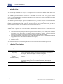
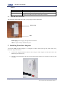
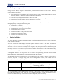
Design of Systems on Silicon
DH10PF User Interface Manual
HANTZ
+ PARTNER
The Upgrade Company! www.hantz.com
DH10PF User Manual
Corporate Headquarters
Design of Systems on Silicon
Charles Robert Darwin, 2
46980 Paterna – Valencia
Spain
Tel:
Fax:
WWW:
Email:
+34.96.136.6004
+34.96.136.6250
http://www.ds2.es
[email protected]
Design of Systems on Silicon
PAGE 2 OF 16
MG-TI-C2-WISC-DH10PF USER INTERFACE MANUAL-1.1
DH10PF User Manual
IMPORTANT NOTICE TO THE USER
DS2 PROVIDES THIS MANUAL “AS IS” WITHOUT WARRANTY OF ANY KIND, EITHER
EXPRESS OR IMPLIED, INCLUDING BUT NOT LIMITED TO THE IMPLIED WARRANTIES
OR CONDITIONS OF MERCHANTABILITY, FITNESS FOR A PARTICULAR PURPOSE OR
NON-INFRINGEMENT.
IN NO EVENT SHALL DS2, ITS DIRECTORS, OFFICERS,
EMPLOYEES OR AGENTS BE LIABLE FOR ANY INDIRECT, SPECIAL, INCIDENTAL, OR
CONSEQUENTIAL DAMAGES FOR LOSS OF PROFITS, LOSS OF BUSINESS, PROPERTY
DAMAGE, PERSONAL INJURY OR LIABILITY, LOSS OF USE OR DATA, INTERRUPTION OF
BUSINESS AND THE LIKE, EVEN IF DS2 HAS BEEN ADVISED OF THE POSSIBILITY OF
SUCH DAMAGES ARISING FROM ANY DEFECT OR ERROR IN THIS MANUAL OR
PRODUCT.
No part of this manual, including the products and software described in it may be reproduced,
transmitted, transcribed, stored in a retrieval system, or translated into any language in any form
or any means, without the express written permission of Design of Systems on Silicon (DS2).
Product warranty or service will not be extended if: (1) the product is repaired, modified or altered,
unless such repair, modification or alteration is authorized in writing by DS2; or (2) the serial
number of the product is defaced or missing.
Products and corporate names appearing in this manual may or may not be registered trademarks
or copyrights of their respective companies, and are used only for identification or explanation and
to the owners’ benefit, without intent to infringe. All product and brand names used in this
manual are used for identification purposes only and may be the registered trademarks of their
respective owners. Windows and the Windows environment are either registered trademarks or
trademarks of Microsoft Corporation in the United States and/or other countries. Linux is a
registered trademark of Linus Torvalds in the US and other countries. Linux man pages obtained
from the public domain.
For previous or updated manuals, BIOS, drivers, or product release information, contact DS2 at
http://www.ds2.es or through any of the means indicated on the previous page.
SPECIFICATIONS AND INFORMATION CONTAINED IN THIS MANUAL ARE FURNISHED
FOR INFORMATIONAL USE ONLY, AND ARE SUBJECT TO CHANGE AT ANY TIME
WITHOUT NOTICE, AND SHOULD NOT BE CONSTRUED AS A COMMITMENT BY DS2.
DS2 ASSUMES NO RESPONSIBILITY OR LIABILITY FOR ANY ERRORS OR INACCURACIES
THAT MAY APPEAR IN THIS MANUAL, INCLUDING THE PRODUCTS AND SOFTWARE
DESCRIBED IN IT.
Copyright © 2007, Design of Systems on Silicon. All Rights Reserved.
Design of Systems on Silicon
PAGE 3 OF 16
MG-TI-C2-WISC-DH10PF USER INTERFACE MANUAL-1.1
DH10PF User Manual
Table of Contents
IMPORTANT NOTICE TO THE USER .........................................................................................................3
1
Introduction ..............................................................................................................................................5
2
Adapter Description................................................................................................................................5
2.1
2.2
FRONT PANEL DESCRIPTION ..................................................................................................................5
REAR AND LOWER CONNECTIONS ........................................................................................................7
3
Installing Powerline Adapters ..............................................................................................................7
4
One Button Security Setup (OBUS) .....................................................................................................8
4.1
4.2
CONFIGURING A PRIVATE POWERLINE NETWORK ................................................................................8
ADDING NEW POWERLINE ADAPTERS TO AN EXISTING PRIVATE POWERLINE NETWORK ....................8
5
Factory reset procedure...........................................................................................................................9
6
Status indicator ........................................................................................................................................9
6.1
6.2
6.3
POINT TO POINT NETWORK .................................................................................................................10
POINT TO MULTIPOINT NETWORK .......................................................................................................11
NEIGHBOURING NETWORKS................................................................................................................13
7
Troubleshooting Guide ........................................................................................................................14
8
Safety advise...........................................................................................................................................14
9
Abbreviations.........................................................................................................................................15
Design of Systems on Silicon
PAGE 4 OF 16
MG-TI-C2-WISC-DH10PF USER INTERFACE MANUAL-1.1
DH10PF User Manual
1
Introduction
The scope of this document is to provide a description of the physical user interface of the DS2’s new
Reference Design DH10PF in-home powerline adapter.
The DH10PF powerline adapter incorporates an AC filter and a rear socket. The purpose of this
design is to facilitate the direct connection of the adapter to a wall power outlet without depriving the
user of the use of this outlet.
The DH10PF powerline adapter provides a link between the powerline network and a Fast Ethernet
10/100M port and an auxiliary filtered output for other appliances. The design is such that on the one
hand it avoids limiting the wall socket just for PLC purposes and on the other hand provides a
filtered socket to avoid the adverse effects of appliances connected to it.
The adapter has two buttons and two LEDs that allow the user to configure a secure PLC network
without using a computer and it will also indicate the estimated channel capacity at application layer
in the receiver adapter. The main features covered are:
•
•
•
•
One Button Security Setup: manual configuration of Fixed AP (Access Point) and automatic
generation of an Encryption Key and a Network Identifier, used to guarantee network
security, and exchange of these keys between adapters using only one button;
Throughput indicator: with a three-colour LED, three different levels of estimated throughput
at application layer will be shown in the receiver adapter;
Manual factory reset.
Stand-by mode.
The minimum firmware level including the full set of above features for DH10PF is Spirit 2.2.7.
2
2.1
Adapter Description
Front panel description
Definition
Power/Standby button
(ON/SBY)
Config /Factory Reset
button
(CONFIG/F RST)
“STATUS” indication
“AP” indication
Design of Systems on Silicon
Function
Used to switch the adapter between ON and STANDBY (minimum
power consumption setting). Pressing the button again will turn on
the adapter. By default adapter is ON when plugged.
Used to implement “One Button Security Setup” and “Factory Reset”
features.
LED indicates if adapter is powered ON/OFF and shows the
application throughput level available in the link (“Throughput
Indicator”).
LED indicates whether the device is configured as a Fixed AP (Access
Point or master) or EP (End Point or slave).
PAGE 5 OF 16
MG-TI-C2-WISC-DH10PF USER INTERFACE MANUAL-1.1
DH10PF User Manual
The following photograph shows the front panel of the adapter.
“ON/SBY” button
“CONFIG/F RST” button
“STATUS” indicator LED
“AP” indicator LED
The meanings of the various LEDs and buttons are given in the following tables:
“STATUS” Indicator
Colour
RED
Adapter
Status
OFF
(STANDBY)
ON
ORANGE
ON
GREEN
ON
BLINKING
(in RED, ORANGE
or GREEN)
ON
LOW RED
Meaning
Adapter is in Standby mode
Adapter is ON.
If PLC link, Estimated Application Throughput <
Threshold 1 (6Mbps = 1 SDTV)
If PLC link, Threshold 1 (6Mbps = 1 SDTV) <
Estimated Application Throughput
< Threshold 2 (12Mbps = 1 HDTV)
If PLC link, Estimated Application Throughput >
Threshold 2 (12Mbps = 1 HDTV)
Traffic in the Ethernet port
“AP” Indicator
LED status
Meaning
OFF
ON
BLINKING
Adapter configured as EP
Adapter configured as Fixed AP (orange light)
Fixed AP in searching mode or EP in configuration mode.
3 FLASHES
AP has exchanged keys with EP, and it has finished its configuration
Design of Systems on Silicon
PAGE 6 OF 16
MG-TI-C2-WISC-DH10PF USER INTERFACE MANUAL-1.1
DH10PF User Manual
Buttons:
Button
ON/SBY
CONFIG/F RST
2.2
Meaning
Powers the adapter OFF (STANDBY) and powers it ON.
Configuration button when pressed 2 seconds. Also performs a
factory reset when pressed for more than 8 seconds.
Rear and lower connections
The following photograph shows the power plug and LAN connections.
Power plug
LAN
Connector Definitions:
Power plug: Power supply and powerline connector
LAN: 1x RJ-45 LAN10/100 Ethernet port
3
Installing Powerline Adapters
To connect each powerline adapter to a computer or other device (Set Top Box, DSL router, etc.),
follow the steps listed below:
1.
Connect the supplied Ethernet cable to the LAN port of the adapter and the other end to the
Ethernet port of the device;
2.
Plug the powerline adapter into any AC electrical outlet. After a few seconds it will be up and
running.
Design of Systems on Silicon
PAGE 7 OF 16
MG-TI-C2-WISC-DH10PF USER INTERFACE MANUAL-1.1
DH10PF User Manual
4
One Button Security Setup (OBUS)
By default, powerline adapters come without a network identifier and without an encryption key. As
a result, when they are plugged into the mains a new PLC network will be created (called public
network). It will operate smoothly, but without a secure configuration. In other words, any nearby
PLC adapter (wanted or unwanted) without network ID and encryption key connected to the same
electrical grid will become part of this public PLC network. That is why it is recommended to
configure a private PLC network (with a unique network identifier and encryption key) for
guarantying the security of the home network.
4.1
Configuring a private powerline network
It is recommended to choose as Fixed AP the adapter that will be connected to the ISP broadband
connection (i.e. DSL router, cable modem, etc.), if any, or to the data or media source device (i.e.
Media Center PC, etc.). Only one Fixed AP must exist in the network.
To configure a private powerline network, perform the following steps:
1.
The first step is to configure the Fixed AP adapter. Press the “CONFIG/F RST” button for
around two seconds until the AP indicator starts blinking to configure the selected adapter as
a Fixed AP. Random Network ID and Encryption Key will be generated automatically and
auto-configured. The AP indicator LED of the adapter will be solid orange;
2.
To add one or more EPs to the network, press the “CONFIG/F RST” button again in the AP
adapter until its AP indicator starts blinking in order to open a configuration period (around
30 seconds);
3.
During the configuration period of the AP adapter you must press the “CONFIG/F RST”
buttons for two seconds in the EP adapters until their AP indicator starts blinking;
4.
All the adapters complete the configuration process successfully when their AP indicator
flashes three times for 0.5 seconds and they return to normal operation mode as EPs (their AP
indicator will remain OFF). The only AP indicator that must remain ON is that of the AP
adapter;
5.
If there is more than one AP device or if there is no AP device, refer to Section 7.
4.2
Adding new powerline adapters to an existing private powerline network
To add additional powerline devices to an existing network, perform the following steps:
1.
Identify which is the AP adapter in an existing PLC network. The AP adapter always shows
its AP indicator ON in orange. The other adapters are EPs and their AP indicators will be
OFF;
2.
Next, press “CONFIG/F RST” button for around two seconds on the AP adapter until its AP
indicator starts blinking. This opens a configuration period of 30 seconds;
3.
During this configuration period, press the “CONFIG/F RST” button on the new EP
adapter(s) until their AP indicator starts blinking, then release the button. Exchanging of
Network ID and Encryption Key between AP and new EPs is done automatically. All the new
adapters and the AP device finish their configuration process successfully when their AP
indicator flashes three times during 0.5 seconds. All adapters then return to normal operation
mode belonging to the same powerline network.
Design of Systems on Silicon
PAGE 8 OF 16
MG-TI-C2-WISC-DH10PF USER INTERFACE MANUAL-1.1
DH10PF User Manual
5
Factory reset procedure
Doing a Factory Reset, adapter’s configuration parameters are set back to their factory default,
perform the following steps:
1.
2.
3.
4.
Press an adapter’s “CONFIG/F RST” button for at least eight seconds (its AP indicator will be
blinking). When AP indicator switches OFF, release the button;
After five seconds, STATUS indicator will be also OFF;
At this time, the adapter resets its configuration to factory default settings and auto-reboots;
The adapter boots successfully and is configured as a new EP.
The most important factory settings in a DS2’s powerline adapter are presented below, customers can
change any factory setting parameter using API.
•
•
•
•
•
•
•
•
6
Default IP is 10.10.1.69
Default configuration password is “paterna”
Default factory reset password is “betera”
Default MAC mode is IHAV
Default node type is End Point
Default network ID is the public network ID
Default Encryption Key is none.
Default CoS configuration is none.
Status indicator
The Status indicator shows the estimated available level of throughput at application layer in function
of the defined thresholds.
There are three levels of throughput indicated by three different colours of the LED. A particular
adapter shows, with one colour, the throughput level with reference to the adapter sending the most
data to it. In case of a network consisting of two adapters, they always show the level of throughput
with reference to the other. However, in the case of a network of three or more adapters, each one
internally measures the amount of bytes received from the other adapters in the network and only
shows the level of throughput with reference to the one that is sending the most data.
A throughput estimator also keeps track of the number of neighbouring networks since available
bandwidth will be divided between them when sharing the PLC channel.
The thresholds of application throughput are preconfigured in the system as shown in table below.
However, they can be changed using SCP (Secure Configuration Protocol, that is DS2’s layer 2
protocol) commands, Factory Settings or API to adapt them to customer’s needs.
Colour
RED
ORANGE
GREEN
BLINKING in RED,
ORANGE or GREEN
Meaning
Estimated Application Throughput < Threshold 1 (6Mbps)
Threshold 1 (6Mbps) < Estimated Application Throughput
< Threshold 2 (12Mbps)
Estimated Application Throughput > Threshold 2 (12Mbps)
Traffic in the Ethernet port (for each estimated throughput level)
The parameters that control the thresholds internally in the system via SCP or Factory Settings are
four (LED_TH1, LED_TH2, LED_TH3 and LED_TH4), and depending on the percentage of errors
measured in the channel they will be chosen to show the quality level in next way:
Design of Systems on Silicon
PAGE 9 OF 16
MG-TI-C2-WISC-DH10PF USER INTERFACE MANUAL-1.1
DH10PF User Manual
Threshold1 corresponds to:
• LED_TH3 for a percentage of errors in the channel lower than 5%
• LED_TH1 for a percentage of errors in the channel equal or higher than 5%
Threshold2 corresponds to:
• LED_TH4 for a percentage of errors in the channel lower than 5%
• LED_TH2 for a percentage of errors in the channel equal or higher than 5%
The PLC adapter is only aware of the PHY layer, and therefore the internal thresholds are referred to
that layer, not the application throughput.
The translation from PHY throughput to Estimated Application Throughput can be approximated by:
0.4*PHY = Application (if errors are > 5%)
0.5*PHY = Application (if errors are < 5%)
That is why internally the default values for the thresholds (in Mbps) are the following. These values
might be changed in order to fit customer requirements for Status indicator levels.
6.1
LED_TH1 = 15
LED_TH2 = 30
LED_TH3 = 12
LED_TH4 = 24
Point to point network
•
Case 1: Estimated application throughput is less than 6 Mbps. The PLC channel is not able to
transmit an SDTV channel. The Status indicator LED will be RED as shown in the following
figure:
•
Case 2: Estimated application throughput is greater than 6 Mbps but less than 12 Mbps. The
PLC channel is able to transmit an SDTV channel, but not two SDTV channels simultaneously
or one HDTV channel. The Status indicator LED will be ORANGE as shown in the following
figure:
Design of Systems on Silicon
PAGE 10 OF 16
MG-TI-C2-WISC-DH10PF USER INTERFACE MANUAL-1.1
DH10PF User Manual
•
6.2
Case 3: Estimated application throughput is greater than 12 Mbps. The PLC channel is able to
play at least two SDTV channels or 1 HDTV. The Status indicator LED will be GREEN as
shown in the following figure:
Point to multipoint network
In the case where the PLC network is composed of three or more adapters, similar situations could
arise as with a point to point network. These are illustrated in the following figures:
Design of Systems on Silicon
PAGE 11 OF 16
MG-TI-C2-WISC-DH10PF USER INTERFACE MANUAL-1.1
DH10PF User Manual
The Status indicator in each adapter will show the estimated application level of the PLC link from
which it is receiving the most amount of traffic at any given time. The Status indicator in PLC adapter
3, for example, could be showing a level of throughput available from PLC adapter 2 for a period of
time as illustrated in the figure above. However, traffic flow could change through user intervention
and then the Status indicator in PLC adapter 3 could show the level with reference to the PLC adapter
1 link, as shown in the following figure.
Design of Systems on Silicon
PAGE 12 OF 16
MG-TI-C2-WISC-DH10PF USER INTERFACE MANUAL-1.1
DH10PF User Manual
6.3
Neighbouring networks
The Status indicator also takes into account the possibility of having neighbouring networks. In such a
case, the throughput evaluator will divide the available bandwidth in two when there is visibility
between any two networks since the PLC channel must be shared on a time basis. In the following
figure, an example of an isolated network is first shown.
In next figure, the previous network (network 1) sees a new neighbouring network (network 2), and a
new evaluation of throughput is made to show the user that channel conditions have changed and
available bandwidth has decreased:
Design of Systems on Silicon
PAGE 13 OF 16
MG-TI-C2-WISC-DH10PF USER INTERFACE MANUAL-1.1
DH10PF User Manual
7
Troubleshooting Guide
The powerline adapter has been designed to be a reliable and easy-to-use home network device.
However, should you experience any problems, please refer to the list below to aid in
troubleshooting.
1.
There is more than one AP in the network because configuration protocol did not finish
correctly:
•
•
•
•
2.
SDTV video streaming is not running:
•
•
•
•
•
•
3.
There may be only one Fixed AP in a network. Verify that this is the case by examining
the AP indicator LED for all adapters;
If there is more than one AP, it means that key exchange process has failed;
Perform a factory reset on the adapter you do not wish to be designated as an AP (see
Section 5 for the Factory Reset procedure);
Repeat network configuration procedure again (see Section 4.2).
Check the STATUS indicator LED in the adapter connected to the STB;
If the indicator is RED this means that the PLC link is not able to play a SDTV streaming;
Try to reposition the adapter in other outlet in order to obtain a ORANGE or GREEN
indication;
If indicator is ORANGE or GREEN, it should now be able to play an SDTV video. Verify
this by confirming that the STATUS indicator LED is blinking when the video is running.
This means that there is activity in the Ethernet connector;
If the LED is not blinking check that the Ethernet cable is correctly connected;
If the LED is blinking and there is still no video streaming, check the settings in devices
connected to the PLC adapters (STB, DSL router, PC, video server, etc.).
HDTV video streaming is not running:
•
•
•
•
•
•
Check the STATUS indicator LED in the adapter connected to the STB;
If the indicator is RED or ORANGE this means that the PLC link is not able to play a
HDTV streaming;
Try to reposition the adapter in other outlet in order to obtain a GREEN indication;
If the indicator is GREEN, it should now be able to play a HDTV video. Verify this by
confirming that the STATUS indicator LED is blinking when the video is running. This
means that there is activity in the Ethernet connector;
If the LED is not blinking check that the Ethernet cables are correctly connected;
If the LED is blinking and there is still no video streaming, check the settings in devices
connected to PLC adapters (STB, DSL router, PC, video server, etc.).
Note: If the HDTV video bandwidth is lower than 12Mbps, it may be possible to stream the
video with an ORANGE STATUS indicator in some cases.
8
Safety advise
DH10PF integrated outlet is rated for maximum 16A (recommended maximum 10A).
Do not connect loads requiring higher currents.
Design of Systems on Silicon
PAGE 14 OF 16
MG-TI-C2-WISC-DH10PF USER INTERFACE MANUAL-1.1
DH10PF User Manual
9
Abbreviations
The following is a list of abbreviations used in this manual.
Abbreviation
3DES
AES
AP
DES
EP
FW
GUI
HDTV
ISP
NetID
NVRAM
PC
PLC
SDTV
STB
Design of Systems on Silicon
Meaning
Triple DES
Advanced Encryption Standard
Access Point
Data Encryption Standard
End Point
Firmware
Graphical User Interface
High Definition TV
Internet Service Provider
Network Identifier
Non-volatile RAM
Personal Computer
Powerline Communications
Standard Definition TV
Set Top Box
PAGE 15 OF 16
MG-TI-C2-WISC-DH10PF USER INTERFACE MANUAL-1.1
DH10PF User Manual
© 2007 Design of Systems on Silicon S.A.
All rights reserved. No part of this document may be reproduced or transmitted in any form or by
any means, without the prior written consent of Design of Systems on Silicon. Design of Systems
on Silicon will not take any responsibility for any errors resulting from the use of the information
contained herein, nor take any responsibility for the misuse of its product. Design of Systems on
Silicon reserves the right to make changes in its products or product specification to improve
function or design at any time without notice.
Design of Systems on Silicon
PAGE 16 OF 16
MG-TI-C2-WISC-DH10PF USER INTERFACE MANUAL-1.1
HANTZ
+ PARTNER
The Upgrade Company! www.hantz.com
Deutschland:
Tel.: 0761 / 59 21 00
Fax: 0761 / 58 52 28
Schweiz:
Tel.: 061 / 27 311 - 31
Fax: 061 / 27 311 - 39
Österreich:
Tel.: 01 / 58 55 430
Fax: 01 / 58 55 460