1
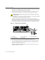
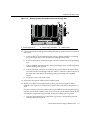
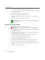
Enterasys Matrix™ X Router DC Power Supply Installation Guide P/N 9034200 Electrical Hazard: Only qualified personnel should perform installation procedures. Riesgo Electrico: Solamente personal calificado debe realizar procedimientos de instalacion. Elektrischer Gefahrenhinweis: Installationen sollten nur durch ausgebildetes und qualifiziertes Personal vorgenommen werden. Notice Enterasys Networks reserves the right to make changes in specifications and other information contained in this document and its web site without prior notice. The reader should in all cases consult Enterasys Networks to determine whether any such changes have been made. The hardware, firmware, or software described in this document is subject to change without notice. IN NO EVENT SHALL ENTERASYS NETWORKS BE LIABLE FOR ANY INCIDENTAL, INDIRECT, SPECIAL, OR CONSEQUENTIAL DAMAGES WHATSOEVER (INCLUDING BUT NOT LIMITED TO LOST PROFITS) ARISING OUT OF OR RELATED TO THIS DOCUMENT, WEB SITE, OR THE INFORMATION CONTAINED IN THEM, EVEN IF ENTERASYS NETWORKS HAS BEEN ADVISED OF, KNEW OF, OR SHOULD HAVE KNOWN OF, THE POSSIBILITY OF SUCH DAMAGES. Enterasys Networks, Inc. 50 Minuteman Road Andover, MA 01810 © 2008 Enterasys Networks, Inc. All rights reserved. Part Number: 9034200 April 2008 ENTERASYS, ENTERASYS NETWORKS, ENTERASYS MATRIX, ENTERASYS NETSIGHT, LANVIEW, WEBVIEW, and any logos associated therewith, are trademarks or registered trademarks of Enterasys Networks, Inc., in the United States and other countries. All other product names mentioned in this manual may be trademarks or registered trademarks of their respective companies. Documentation URL: http://www.enterasys.com/support/manuals Documentacion URL: http://www.enterasys.com/support/manuals Dokumentation im Internet: http://www.enterasys.com/support/manuals i Regulatory Compliance Information Federal Communications Commission (FCC) Notice This device complies with Part 15 of the FCC rules. Operation is subject to the following two conditions: (1) this device may not cause harmful interference, and (2) this device must accept any interference received, including interference that may cause undesired operation. NOTE: This equipment has been tested and found to comply with the limits for a class A digital device, pursuant to Part 15 of the FCC rules. These limits are designed to provide reasonable protection against harmful interference when the equipment is operated in a commercial environment. This equipment uses, generates, and can radiate radio frequency energy and if not installed in accordance with the operator’s manual, may cause harmful interference to radio communications. Operation of this equipment in a residential area is likely to cause interference in which case the user will be required to correct the interference at his own expense. WARNING: Changes or modifications made to this device which are not expressly approved by the party responsible for compliance could void the user’s authority to operate the equipment. Industry Canada Notice This digital apparatus does not exceed the class A limits for radio noise emissions from digital apparatus set out in the Radio Interference Regulations of the Canadian Department of Communications. Le présent appareil numérique n’émet pas de bruits radioélectriques dépassant les limites applicables aux appareils numériques de la class A prescrites dans le Règlement sur le brouillage radioélectrique édicté par le ministère des Communications du Canada. Class A ITE Notice WARNING: This is a Class A product. In a domestic environment this product may cause radio interference in which case the user may be required to take adequate measures. Clase A. Aviso de ITE ADVERTENCIA: Este es un producto de Clase A. En un ambiente doméstico este producto puede causar interferencia de radio en cuyo caso puede ser requerido tomar medidas adecuadas. Klasse A ITE Anmerkung WARNHINWEIS: Dieses Produkt zählt zur Klasse A ( Industriebereich ). In Wohnbereichen kann es hierdurch zu Funkstörungen kommen, daher sollten angemessene Vorkehrungen zum Schutz getroffen werden. Product Safety This product complies with the following: UL 60950, CSA C22.2 No. 60950, 2006/95/EC, EN 60950, IEC 60950, EN 60825, 21 CFR 1040.10. Seguridad del Producto El producto de Enterasys cumple con lo siguiente: UL 60950, CSA C22.2 No. 60950, 73/23/EEC, EN 60950, IEC 60950, EN 60825, 21 CFR 1040.10. Produktsicherheit Dieses Produkt entspricht den folgenden Richtlinien: UL 60950, CSA C22.2 No. 60950, 73/23/EEC, EN 60950, IEC 60950, EN 60825, 21 CFR 1040.10. ii Electromagnetic Compatibility (EMC) This product complies with the following: 47 CFR Parts 2 and 15, CSA C108.8, 2006/95/EC, EN 55022, EN 61000‐3‐2, EN 61000‐3‐3, EN 55024, AS/NZS CISPR 22, VCCI V‐3. Compatibilidad Electromágnetica (EMC) Este producto de Enterasys cumple con lo siguiente: 47 CFR Partes 2 y 15, CSA C108.8, 89/336/EEC, EN 55022, EN 55024, EN 61000‐3‐2, EN 61000‐3‐3, AS/NZS CISPR 22, VCCI V‐3. Elektro- magnetische Kompatibilität ( EMC ) Dieses Produkt entspricht den folgenden Richtlinien: 47 CFR Parts 2 and 15, CSA C108.8, 89/336/EEC, EN 55022, EN 61000‐3‐2, EN 61000‐3‐3, EN 55024, AS/NZS CISPR 22, VCCI V‐3. Hazardous Substances This product complies with the requirements of European Directive, 2002/95/EC, Restriction of Hazardous Substances (RoHS) in Electrical and Electronic Equipment. European Waste Electrical and Electronic Equipment (WEEE) Notice In accordance with Directive 2002/96/EC of the European Parliament on waste electrical and electronic equipment (WEEE): 1. The symbol above indicates that separate collection of electrical and electronic equipment is required and that this product was placed on the European market after August 13, 2005, the date of enforcement for Directive 2002/96/EC. 2. When this product has reached the end of its serviceable life, it cannot be disposed of as unsorted municipal waste. It must be collected and treated separately. 3. It has been determined by the European Parliament that there are potential negative effects on the environment and human health as a result of the presence of hazardous substances in electrical and electronic equipment. 4. It is the users’ responsibility to utilize the available collection system to ensure WEEE is properly treated. For information about the available collection system, please go to www.enterasys.com/services/support/ or contact Enterasys Customer Support at 353 61 705586 (Ireland). iii ѻક䇈ᯢк䰘ӊ Supplement to Product Instructions 䚼ӊৡ⿄ (Parts) 䞥ሲ䚼ӊ (Metal Parts) ⬉䏃ഫ (Circuit Modules) ⬉㓚ঞ⬉㓚㒘ӊ (Cables & Cable Assemblies) ล᭭㘮ড়⠽䚼ӊ (Plastic and Polymeric parts) ⬉䏃ᓔ݇ (Circuit Breakers) ƻ˖ 䪙 3E ᳝↦᳝ᆇ⠽䋼ܗ㋴(Hazardous Substance) ∲ 䬝 ݁Ӌ䫀 ⒈㘨㣃 +J &G &U 3%% ⒈Ѡ㣃䝮 3%'( h ƻ ƻ h ƻ ƻ h ƻ ƻ h ƻ ƻ h ƻ ƻ h ƻ ƻ ƻ ƻ ƻ ƻ ƻ h ƻ ƻ h h ƻ ƻ 㸼⼎䆹᳝↦᳝ᆇ⠽䋼䆹䚼ӊ᠔᳝ഛ䋼ᴤ᭭Ёⱘ䞣ഛ SJ/T 11363-2006 ᷛޚ㾘ᅮⱘ䰤䞣㽕∖ҹϟDŽ Indicates that the concentration of the hazardous substance in all homogeneous materials in the parts is below the relevant threshold of the SJ/T 11363-2006 standard. h˖ 㸼⼎䆹᳝↦᳝ᆇ⠽䋼㟇ᇥ䆹䚼ӊⱘᶤϔഛ䋼ᴤ᭭Ёⱘ䞣䍙ߎSJ/T 11363-2006 ᷛޚ㾘ᅮⱘ䰤䞣㽕∖DŽ Indicates that the concentration of the hazardous substance of at least one of all homogeneous materials in the parts is above the relevant threshold of the SJ/T 11363-2006 standard. ᇍ䫔ଂП᮹ⱘ᠔ଂѻકᴀ㸼ᰒ⼎ ߃߯կᑨ䫒ⱘ⬉ᄤֵᙃѻકৃ㛑ࣙ䖭ѯ⠽䋼DŽ⊼ᛣ᠔ଂѻકЁৃ㛑Ӯгৃ㛑ϡӮ᳝᠔᳝᠔߫ⱘ䚼ӊDŽ This table shows where these substances may be found in the supply chain of Enterasys’ electronic information products, as of the date of sale of the enclosed product. Note that some of the component types listed above may or may not be a part of the enclosed product. 䰸䴲⡍߿ⱘᷛ⊼ℸᷛᖫЎ䩜ᇍ᠔⍝ঞѻકⱘ⦃ֱՓ⫼ᳳᷛᖫᶤѯ䳊䚼ӊӮ ᳝ϔϾϡৠⱘ⦃ֱՓ⫼ᳳ՟བ⬉∴ऩܗഫ䌈݊ѻકϞ ℸ⦃ֱՓ⫼ᳳ䰤া䗖⫼ѢѻકᰃѻકݠЁ᠔㾘ᅮⱘᴵӊϟᎹ The Environmentally Friendly Use Period (EFUP) for all enclosed products and their parts are per the symbol shown here, unless otherwise marked. Certain parts may have a different EFUP (for example, battery modules) and so are marked to reflect such. The Environmentally Friendly Use Period is valid only when the product is operated under the conditions defined in the product manual. iv 50 VCCI Notice This is a class A product based on the standard of the Voluntary Control Council for Interference by Information Technology Equipment (VCCI). If this equipment is used in a domestic environment, radio disturbance may arise. When such trouble occurs, the user may be required to take corrective actions. BSMI EMC Statement — Taiwan This is a class A product. In a domestic environment this product may cause radio interference in which case the user may be required to take adequate measures. Safety Information Class 1 Laser Transceivers The single mode interface modules use Class 1 laser transceivers. Read the following safety information before installing or operating these modules. The Class 1 laser transceivers use an optical feedback loop to maintain Class 1 operation limits. This control loop eliminates the need for maintenance checks or adjustments. The output is factory set, and does not allow any user adjustment. Class 1 Laser transceivers comply with the following safety standards: • 21 CFR 1040.10 and 1040.11 U.S. Department of Health and Human Services (FDA). • IEC Publication 825 (International Electrotechnical Commission). • CENELEC EN 60825 (European Committee for Electrotechnical Standardization). When operating within their performance limitations, laser transceiver output meets the Class 1 accessible emission limit of all three standards. Class 1 levels of laser radiation are not considered hazardous. When the connector is in place, all laser radiation remains within the fiber. The maximum amount of radiant power exiting the fiber (under normal conditions) is ‐12.6 dBm or 55 x 10‐6 watts. Removing the optical connector from the transceiver allows laser radiation to emit directly from the optical port. The maximum radiance from the optical port (under worst case conditions) is 0.8 W cm‐2 or 8 x 10³ W m2 sr‐1. Do not use optical instruments to view the laser output. The use of optical instruments to view laser output increases eye hazard. When viewing the output optical port, power must be removed from the network adapter. v Declaration of Conformity Application of Council Directive(s): Manufacturer’s Name: Manufacturer’s Address: European Representative Address: Conformance to Directive(s)/Product Standards: Equipment Type/Environment: 2004/108/EC 2006/95/EC Enterasys Networks, Inc. 50 Minuteman Road Andover, MA 01810 USA Enterasys Networks, Ltd. Nexus House, Newbury Business Park London Road, Newbury Berkshire RG14 2PZ, England EC Directive 2004/95/EC EN 55022 EN 61000‐3‐2 EN 61000‐3‐3 EN 55024 EC Directive 2004/108/EC EN 60950 EN 60825 Networking Equipment, for use in a Commercial or Light Industrial Environment. Enterasys Networks, Inc. declares that the equipment packaged with this notice conforms to the above directives. vi Enterasys Networks, Inc. Firmware License Agreement BEFORE OPENING OR UTILIZING THE ENCLOSED PRODUCT, CAREFULLY READ THIS LICENSE AGREEMENT. This document is an agreement (“Agreement”) between the end user (“You”) and Enterasys Networks, Inc., on behalf of itself and its Affiliates (as hereinafter defined) (“Enterasys”) that sets forth Your rights and obligations with respect to the Enterasys software program/firmware (including any accompanying documentation, hardware or media) (“Program”) in the package and prevails over any additional, conflicting or inconsistent terms and conditions appearing on any purchase order or other document submitted by You. “Affiliate” means any person, partnership, corporation, limited liability company, other form of enterprise that directly or indirectly through one or more intermediaries, controls, or is controlled by, or is under common control with the party specified. This Agreement constitutes the entire understanding between the parties, with respect to the subject matter of this Agreement. The Program may be contained in firmware, chips or other media. BY INSTALLING OR OTHERWISE USING THE PROGRAM, YOU REPRESENT THAT YOU ARE AUTHORIZED TO ACCEPT THESE TERMS ON BEHALF OF THE END USER (IF THE END USER IS AN ENTITY ON WHOSE BEHALF YOU ARE AUTHORIZED TO ACT, “YOU” AND “YOUR” SHALL BE DEEMED TO REFER TO SUCH ENTITY) AND THAT YOU AGREE THAT YOU ARE BOUND BY THE TERMS OF THIS AGREEMENT, WHICH INCLUDES, AMONG OTHER PROVISIONS, THE LICENSE, THE DISCLAIMER OF WARRANTY AND THE LIMITATION OF LIABILITY. IF YOU DO NOT AGREE TO THE TERMS OF THIS AGREEMENT OR ARE NOT AUTHORIZED TO ENTER INTO THIS AGREEMENT, ENTERASYS IS UNWILLING TO LICENSE THE PROGRAM TO YOU AND YOU AGREE TO RETURN THE UNOPENED PRODUCT TO ENTERASYS OR YOUR DEALER, IF ANY, WITHIN TEN (10) DAYS FOLLOWING THE DATE OF RECEIPT FOR A FULL REFUND. IF YOU HAVE ANY QUESTIONS ABOUT THIS AGREEMENT, CONTACT ENTERASYS NETWORKS, LEGAL DEPARTMENT AT (978) 684‐1000. You and Enterasys agree as follows: 1. LICENSE. You have the non‐exclusive and non‐transferable right to use only the one (1) copy of the Program provided in this package subject to the terms and conditions of this Agreement. 2. RESTRICTIONS. Except as otherwise authorized in writing by Enterasys, You may not, nor may You permit any third party to: (a) Reverse engineer, decompile, disassemble or modify the Program, in whole or in part, including for reasons of error correction or interoperability, except to the extent expressly permitted by applicable law and to the extent the parties shall not be permitted by that applicable law, such rights are expressly excluded. Information necessary to achieve interoperability or correct errors is available from Enterasys upon request and upon payment of Enterasys’ applicable fee. (b) Incorporate the Program in whole or in part, in any other product or create derivative works based on the Program, in whole or in part. (c) Publish, disclose, copy reproduce or transmit the Program, in whole or in part. (d) Assign, sell, license, sublicense, rent, lease, encumber by way of security interest, pledge or otherwise transfer the Program, in whole or in part. (e) Remove any copyright, trademark, proprietary rights, disclaimer or warning notice included on or embedded in any part of the Program. 3. APPLICABLE LAW. This Agreement shall be interpreted and governed under the laws and in the state and federal courts of the Commonwealth of Massachusetts without regard to its conflicts of laws provisions. You accept the personal jurisdiction and venue of the Commonwealth of Massachusetts courts. None of the 1980 United Nations Convention on the Limitation Period in the International Sale of Goods, and the Uniform Computer Information Transactions Act shall apply to this Agreement. vii 4. EXPORT RESTRICTIONS. You understand that Enterasys and its Affiliates are subject to regulation by agencies of the U.S. Government, including the U.S. Department of Commerce, which prohibit export or diversion of certain technical products to certain countries, unless a license to export the product is obtained from the U.S. Government or an exception from obtaining such license may be relied upon by the exporting party. If the Program is exported from the United States pursuant to the License Exception CIV under the U.S. Export Administration Regulations, You agree that You are a civil end user of the Program and agree that You will use the Program for civil end uses only and not for military purposes. If the Program is exported from the United States pursuant to the License Exception TSR under the U.S. Export Administration Regulations, in addition to the restriction on transfer set forth in Section 1 or 2 of this Agreement, You agree not to (i) reexport or release the Program, the source code for the Program or technology to a national of a country in Country Groups D:1 or E:2 (Albania, Armenia, Azerbaijan, Belarus, Cambodia, Cuba, Georgia, Iraq, Kazakhstan, Laos, Libya, Macau, Moldova, Mongolia, North Korea, the People’s Republic of China, Russia, Tajikistan, Turkmenistan, Ukraine, Uzbekistan, Vietnam, or such other countries as may be designated by the United States Government), (ii) export to Country Groups D:1 or E:2 (as defined herein) the direct product of the Program or the technology, if such foreign produced direct product is subject to national security controls as identified on the U.S. Commerce Control List, or (iii) if the direct product of the technology is a complete plant or any major component of a plant, export to Country Groups D:1 or E:2 the direct product of the plant or a major component thereof, if such foreign produced direct product is subject to national security controls as identified on the U.S. Commerce Control List or is subject to State Department controls under the U.S. Munitions List. 5. UNITED STATES GOVERNMENT RESTRICTED RIGHTS. The enclosed Program (i) was developed solely at private expense; (ii) contains “restricted computer software” submitted with restricted rights in accordance with section 52.227‐19 (a) through (d) of the Commercial Computer Software‐Restricted Rights Clause and its successors, and (iii) in all respects is proprietary data belonging to Enterasys and/or its suppliers. For Department of Defense units, the Program is considered commercial computer software in accordance with DFARS section 227.7202‐3 and its successors, and use, duplication, or disclosure by the U.S. Government is subject to restrictions set forth herein. 6. DISCLAIMER OF WARRANTY. EXCEPT FOR THOSE WARRANTIES EXPRESSLY PROVIDED TO YOU IN WRITING BY ENTERASYS, ENTERASYS DISCLAIMS ALL WARRANTIES, EITHER EXPRESS OR IMPLIED, INCLUDING BUT NOT LIMITED TO IMPLIED WARRANTIES OF MERCHANTABILITY, SATISFACTORY QUALITY, FITNESS FOR A PARTICULAR PURPOSE, TITLE AND NON‐INFRINGEMENT WITH RESPECT TO THE PROGRAM. IF IMPLIED WARRANTIES MAY NOT BE DISCLAIMED BY APPLICABLE LAW, THEN ANY IMPLIED WARRANTIES ARE LIMITED IN DURATION TO THIRTY (30) DAYS AFTER DELIVERY OF THE PROGRAM TO YOU. 7. LIMITATION OF LIABILITY. IN NO EVENT SHALL ENTERASYS OR ITS SUPPLIERS BE LIABLE FOR ANY DAMAGES WHATSOEVER (INCLUDING, WITHOUT LIMITATION, DAMAGES FOR LOSS OF BUSINESS, PROFITS, BUSINESS INTERRUPTION, LOSS OF BUSINESS INFORMATION, SPECIAL, INCIDENTAL, CONSEQUENTIAL, OR RELIANCE DAMAGES, OR OTHER LOSS) ARISING OUT OF THE USE OR INABILITY TO USE THE PROGRAM, EVEN IF ENTERASYS HAS BEEN ADVISED OF THE POSSIBILITY OF SUCH DAMAGES. THIS FOREGOING LIMITATION SHALL APPLY REGARDLESS OF THE CAUSE OF ACTION UNDER WHICH DAMAGES ARE SOUGHT. THE CUMULATIVE LIABILITY OF ENTERASYS TO YOU FOR ALL CLAIMS RELATING TO THE PROGRAM, IN CONTRACT, TORT OR OTHERWISE, SHALL NOT EXCEED THE TOTAL AMOUNT OF FEES PAID TO ENTERASYS BY YOU FOR THE RIGHTS GRANTED HEREIN. viii 8. AUDIT RIGHTS. You hereby acknowledge that the intellectual property rights associated with the Program are of critical value to Enterasys, and, accordingly, You hereby agree to maintain complete books, records and accounts showing (i) license fees due and paid, and (ii) the use, copying and deployment of the Program. You also grant to Enterasys and its authorized representatives, upon reasonable notice, the right to audit and examine during Your normal business hours, Your books, records, accounts and hardware devices upon which the Program may be deployed to verify compliance with this Agreement, including the verification of the license fees due and paid Enterasys and the use, copying and deployment of the Program. Enterasys’ right of examination shall be exercised reasonably, in good faith and in a manner calculated to not unreasonably interfere with Your business. In the event such audit discovers non‐compliance with this Agreement, including copies of the Program made, used or deployed in breach of this Agreement, You shall promptly pay to Enterasys the appropriate license fees. Enterasys reserves the right, to be exercised in its sole discretion and without prior notice, to terminate this license, effective immediately, for failure to comply with this Agreement. Upon any such termination, You shall immediately cease all use of the Program and shall return to Enterasys the Program and all copies of the Program. 9. OWNERSHIP. This is a license agreement and not an agreement for sale. You acknowledge and agree that the Program constitutes trade secrets and/or copyrighted material of Enterasys and/or its suppliers. You agree to implement reasonable security measures to protect such trade secrets and copyrighted material. All right, title and interest in and to the Program shall remain with Enterasys and/or its suppliers. All rights not specifically granted to You shall be reserved to Enterasys. 10. ENFORCEMENT. You acknowledge and agree that any breach of Sections 2, 4, or 9 of this Agreement by You may cause Enterasys irreparable damage for which recovery of money damages would be inadequate, and that Enterasys may be entitled to seek timely injunctive relief to protect Enterasys’ rights under this Agreement in addition to any and all remedies available at law. 11. ASSIGNMENT. You may not assign, transfer or sublicense this Agreement or any of Your rights or obligations under this Agreement, except that You may assign this Agreement to any person or entity which acquires substantially all of Your stock assets. Enterasys may assign this Agreement in its sole discretion. This Agreement shall be binding upon and inure to the benefit of the parties, their legal representatives, permitted transferees, successors and assigns as permitted by this Agreement. Any attempted assignment, transfer or sublicense in violation of the terms of this Agreement shall be void and a breach of this Agreement. 12. WAIVER. A waiver by Enterasys of a breach of any of the terms and conditions of this Agreement must be in writing and will not be construed as a waiver of any subsequent breach of such term or condition. Enterasys’ failure to enforce a term upon Your breach of such term shall not be construed as a waiver of Your breach or prevent enforcement on any other occasion. 13. SEVERABILITY. In the event any provision of this Agreement is found to be invalid, illegal or unenforceable, the validity, legality and enforceability of any of the remaining provisions shall not in any way be affected or impaired thereby, and that provision shall be reformed, construed and enforced to the maximum extent permissible. Any such invalidity, illegality, or unenforceability in any jurisdiction shall not invalidate or render illegal or unenforceable such provision in any other jurisdiction. 14. TERMINATION. Enterasys may terminate this Agreement immediately upon Your breach of any of the terms and conditions of this Agreement. Upon any such termination, You shall immediately cease all use of the Program and shall return to Enterasys the Program and all copies of the Program. ix x Contents Chapter 1: DC Power Supply Installation Overview of the DC Power Supply .....................................................................................................1-2 Power Supply Redundancy Planning ..........................................................................................1-4 Installation Site Requirements ...........................................................................................................1-4 Pre-Installation Tasks ........................................................................................................................1-5 Verify DC Power Compliance of Matrix X Modules .....................................................................1-5 Prepare Site Wiring for DC Power Installation .............................................................................1-8 Unpacking the DC Power Supply .......................................................................................................1-9 Installing the DC Power Supply .......................................................................................................1-10 Removing a Power Supply ...............................................................................................................1-14 Chapter 2: DC Power Supply Specifications Specifications .....................................................................................................................................2-1 Compression Lugs .......................................................................................................................2-2 Power Supply Redundancy ................................................................................................................2-2 Regulatory Compliance ......................................................................................................................2-4 xi xii About This Guide This guide describes the Enterasys Matrix™ X Router DC power supply features and specifications, and provides information to install the power supply in an Enterasys Matrix™ X chassis. Who Should Use This Guide This guide is intended for a network administrator who is responsible for installing and setting up the Enterasys Matrix™ X Router system. Electrical Hazard: Only qualified personnel should install or service this unit. Riesgo Electrico: Nada mas personal capacitado debe de instalar o darle servicio a esta unida. Elektrischer Gefahrenhinweis: Installationen oder Servicearbeiten sollten nur durch ausgebildetes und qualifiziertes Personal vorgenommen werden. Using This Guide For information about ... Refer to ... Features of the DC power supply, installation site requirements, and installation procedures. Chapter 1, DC Power Supply Installation Environmental, operating, and power budgeting specifications for the DC power supply, and regulatory compliances Chapter 2, DC Power Supply Specifications Using the Enterasys Matrix™ X Router Manual Set The following related Enterasys Matrix™ X Router documentation is available: • Enterasys Matrix™ X Router Configuration Guide • Enterasys Matrix™ X Router Command Line Interface Reference Guide • Enterasys Matrix™ X Router Quick Reference Cards • Enterasys Matrix™ X Router Release Notes Matrix X Router DC Power Supply Installation Guide xiii Conventions Used in This Guide Documentation can be accessed on the World Wide Web, at the following URL: http://www.enterasys.com/support/manuals/ Conventions Used in This Guide The following conventions are used in this guide: Note: Calls the reader’s attention to any item of information that may be of special importance. Caution: Contains information essential to avoid damage to the equipment. Precaución: Contiene información esencial para prevenir dañar el equipo. Achtung: Verweißt auf wichtige Informationen zum Schutz gegen Beschädigungen. Electrical Hazard: Warns against an action that could result in personal injury or death due to an electrical hazard. Riesgo Electrico: Advierte contra una acción que pudiera resultar en lesión corporal o la muerte debido a un riesgo eléctrico. Elektrischer Gefahrenhinweis: Warnung vor sämtlichen Handlungen, die zu Verletzung von Personen oder Todesfällen – hervorgerufen durch elektrische Spannung – führen können! Warning: Warns against an action that could result in personal injury or death. Advertencia: Advierte contra una acción que pudiera resultar en lesión corporal o la muerte. Warnhinweis: Warnung vor Handlungen, die zu Verletzung von Personen oder gar Todesfällen führen können! xiv About This Guide Getting Help Getting Help For additional support related to the DC power supply or this document, contact Enterasys Networks using one of the following methods: World Wide Web http://www.enterasys.com/support 1-800-872-8440 (toll-free in U.S. and Canada) For the Enterasys Networks Support toll-free number in your country: Phone http://www.enterasys.com/support [email protected] Internet mail To expedite your message, please type [X-Router] in the subject line. To send comments or suggestions concerning this document to the Technical Publications Department: [email protected] To expedite your message, include the document Part Number in the Email message. Before contacting Enterasys Networks for technical support, have the following information ready: • Your Enterasys Networks service contract number • A description of the failure • A description of any action(s) already taken to resolve the problem (for example, changing mode switches or rebooting the unit) • The serial and revision numbers of all involved Enterasys Networks products in the network • A description of your network environment (such as layout, cable type, other relevant environmental information) • Network load and frame size at the time of trouble (if known) • The device history (for example, if you have returned the device before, or if this a recurring problem) • Any previous Return Material Authorization (RMA) numbers Matrix X Router DC Power Supply Installation Guide xv Getting Help xvi About This Guide 1 DC Power Supply Installation Electrical Hazard: Only qualified personnel should perform installation procedures. Riesgo Electrico: Solamente personal calificado debe realizar procedimientos de instalacion. Elektrischer Gefahrenhinweis: Installationen sollten nur durch ausgebildetes und qualifiziertes Personal vorgenommen werden. This chapter provides installation instructions for the Enterasys Matrix™ X Router DC power supply module (X‐DC). Follow the order of the sections listed below to correctly install the DC power supply. For information about... Refer to page... Overview of the DC Power Supply 1-2 Installation Site Requirements 1-4 Pre-Installation Tasks 1-5 Unpacking the DC Power Supply 1-9 Installing the DC Power Supply 1-10 Removing a Power Supply 1-14 Matrix X Router DC Power Supply Installation Guide 1-1 Overview of the DC Power Supply Overview of the DC Power Supply The DC power supply (X‐DC) can be used in the Enterasys Matrix™ X16‐C, X8‐C, and X4‐C chassis in place of the standard AC power supplies (X‐AC). The DC power supply connects a ‐48/‐60 VDC battery voltage to the backplane of the Enterasys Matrix™ X chassis. Each power supply provides a maximum of 1500 Watts of power. The DC power supply also provides a +5 VDC auxiliary output. Figure 1‐1 and Figure 1‐2 show the front and back views of this power supply. Figure 1-1 Front View of the DC Power Supply 2 1 3 PWR-IN PWR-OUT OFF ON 50A ON 8 1 Circuit breaker 2 Power In and Power Out LEDs 3 Mounting flange and fastener 1-2 DC Power Supply Installation 7 6 5 4 Negative terminal studs 5 Positive terminal studs 6 Plastic protective cover 4 7 8 Earth ground stud Handle Overview of the DC Power Supply Figure 1-2 Back View of the DC Power Supply 1 1 Connector The DC power supply provides the following features: • Input Overload Protection As shown in Figure 1‐1 on page 1‐2, the power supply has a 50A circuit breaker on the front panel, to protect against internal damage due to a catastrophic failure. • Redundancy A maximum of six supplies can be operated in parallel, sharing a common power bus. Failure of any single supply will not affect operation of the power bus. In addition, inadvertent hot‐swapping of energized power supplies will not affect bus operation. This applies to all outputs of the power supply. • Reverse Polarity Protection and Alarm No damage will occur to the power supply if the input voltage is inadvertently reversed. An audible alarm will sound upon reverse polarity. • Visual Indicators As shown in Figure 1‐1 on page 1‐2, the power supply has two LEDs on the front panel. The PWR‐IN LED lights green when the input voltage is above the minimum required to operate. The PWR‐OUT LED lights green if all power supply voltage outputs are in regulation. Matrix X Router DC Power Supply Installation Guide 1-3 Installation Site Requirements Power Supply Redundancy Planning Because chassis system components consume varying amounts of electrical power, Enterasys recommend consulting the module power specifications in “Power Supply Redundancy” on page 2‐2 to guide you in installing the proper number of power supplies for your configuration. Installation Site Requirements The DC power supply must be installed in an Enterasys Matrix™ X chassis located in a Restricted Access Location (RAL). This location should only be accessible by people who have been trained or are technically competent enough to be aware of potential risks of accessing the hazardous areas of the chassis. Locations such as a locked wiring closet or locked cabinet meet this requirement. Warning: Install this module on an Enterasys Matrix™ X chassis that has been installed in a Restricted Access Location only. Access to the equipment by users must be restricted through the use of a tool or lock and key or other means of security and is controlled by the authority responsible for the location. Advertencia: Instalar este modulo en un Enterasys Matrix™ X chassis que ha sido localizado en un lugar de Acceso Restringido. Aceso al equipo debe ser restringido por el responsable del sitio. Warnhinweis: Installieren Sie dieses Modul nur in einem Enterasys Matrix™ X chassis, wenn sich diese in einer zugangsgeschützten Umgebung befinden. Der Bereich zu den Komponenten sollte durch ein Schloß, einen Schlüssel oder sonstigen Sicherungen geschützt und durch einen Verantwortlichen kontrolliert werden. 1-4 DC Power Supply Installation Pre-Installation Tasks Pre-Installation Tasks Complete the following tasks before installing the DC power supply: • Verify DC Power Compliance of Matrix X Modules • Prepare Site Wiring for DC Power Installation (page 1‐8) Verify DC Power Compliance of Matrix X Modules All installed modules must meet both the 940 part number and the 940 revision minimum requirements for DC power. • If you are converting an existing AC‐powered Matrix X Router system to DC power follow the procedure in Converting Existing AC‐powered Matrix X Router Systems to DC. • If the system is a new a Matrix X DC‐powered installation follow the procedure in New DC Power Matrix X System Installations (page 1‐7). Converting Existing AC-powered Matrix X Router Systems to DC If the system currently uses AC power and is transitioning to DC, follow this procedure to verify DC power compliance of all modules. 1. From the CLI, run the show system hardware command. In the following example, output from running the show system hardware cm 1 command is shown to illustrate information for a DC power‐compliant CM module. matrix-x(switch-su)-> show system hardware cm 1 CM SLOT 1 Model: CM Version 1.0 State: Active 905 Part number: 9053454000 905 Serial number: 07420507635A 940 Part number: 9404179000 940 Serial number: 07475281635A Part number: X-CM-00 [truncated] Matrix X Router DC Power Supply Installation Guide 1-5 Pre-Installation Tasks Note: In the CLI output for show system hardware, model name part numbers of modules are labeled “Part number.” 2. Table 1-1 Use the information from the output of the show system hardware command to fill out the worksheet in Table 1‐1 for each module as follows: a. Use the value of “940 Part number:” from the output of the show system hardware command to fill out the 940 Part Number section of Table 1‐1. b. Use the value of “940 Serial number:“ from the output of the show system hardware command to fill out the 940 Serial Number section of Table 1‐1. Worksheet: DC Compliance of Modules in Existing AC Systems Model Part No. 940 Part Number 940 Example: X-CM-00 940 3. 1-6 940 Serial Number DC Compliant? Last 4 digits of 940 Number Site Code Date Code (year, work week) Serial Number Counter Site Code 940 Revision 4179 000 0747 5281 63 5A YES Compare the values in the shaded cells of the completed worksheet in Table 1‐1 to the minimum values shown in Table 1‐3 on page 1‐8 to determine the DC compliance of the installed modules. DC Power Supply Installation Pre-Installation Tasks New DC Power Matrix X System Installations If the system is a new Matrix X DC‐powered installation, follow this procedure to verify DC power compliance of all modules: 1. Obtain the model name and serial number from the front panel of each module to be installed. 2. Using the model name and serial number, fill out the worksheet in Table 1‐2. Table 1-2 Worksheet: DC Compliance of Modules for New DC Systems Model Part No. Example: X-CM-00 3. Front Panel Serial Number DC Compliant? Last 4 digits of 940 Number Date Code (year, work week) Serial Number Counter Site Code 940 Revision 4179 0747 5281 63 5A YES Compare the values in the shaded cells of the completed worksheet in Table 1‐2 to the minimum values shown in Table 1‐3 on page 1‐8 to determine the DC compliance of the modules to be installed. Matrix X Router DC Power Supply Installation Guide 1-7 Pre-Installation Tasks Table 1-3 Minimum Revision of X Modules for DC Power Model Name Minimum 940 Part Number Minimum 940 Revision X-CM-00 4179 5A1 X-T32-00 4167 5A2 X-G32-00 4161 5A3 X-M2-00 4054 5H X-M8-01 4162 5A X-GT16-00 3977 5A X16-FM 4059 5C X8-FM 4055 5B X4-FM 4050 5B X-FAN 4085 5B X-FAN-AC N/A N/A 1. Exception: If an X-CM-00 module meets the Minimum 940 Part Number revision and has a 2 digit 940 revision code of 4X (for example, 41, 42, and so on), the module is DC powercompliant. 2. Exception: If an X-T32-00 module meets the Minimum 940 Part Number revision and has a 2 digit 940 revision code of 4X (for example, 41, 42, and so on), the module is DC powercompliant. 3. Exception: If an X-G32-00 module meets the Minimum 940 Part Number revision and has a 2 digit 940 revision code of 4X (for example, 41, 42, and so on), the module is DC powercompliant. Prepare Site Wiring for DC Power Installation 1. Ensure that a branch circuit disconnect device is installed, and that the device is switched to prevent power from being supplied to the DC power supply. 2. If desired, attach your wiring to the 2‐hole compression lugs provided. For your convenience, Enterasys Networks ships with the DC power supply two 2‐hole compression lugs to which you can connect your wiring (6 AWG). These compression lugs are the correct size to fit over the positive and negative terminal studs. See Chapter 2, DC Power Supply Specifications for more details about the compression lugs. 1-8 DC Power Supply Installation Unpacking the DC Power Supply Warning: To reduce the risk of electric shock or energy hazards: 1. Connect to a reliably grounded 48V source. 2. The branch circuit over current protection must be rated at a maximum 50A for the device. 3. Use only 10mm² or 6 AWG 75C solid copper wires on the device. 4. A readily accessible disconnect device that is suitably approved and rated shall be incorporated in the field wiring. 5. To be installed in a restricted access area in accordance with the NEC or authority having jurisdiction. Advertencia: Para reducir el riesgo de choque electrico: 1. Conectar a una fuente aterrizada de 48V. 2. The branch circuit over current protection must be rated at a maximum 50A for the device. 3. Utilizar unicamente cables de cobre solidos de tipo 75C 10mm² or 6 AWG en el dispositivo. 4. A readily accessible disconnect device that is suitably approved and rated shall be incorporated in the field wiring. 5. Ser instalado en una area de acceso restrictivo, de acuerdo con el NEC o con otra autoridad. Warnhinweis: Reduzieren sie das Risiko von Stromschlägen oder allgemeinen elektrischen Gefahren: 1. Verbinden Sie das Gerät mit einer zuverlässig geerdeten 48 V Stromquelle. 2. Die maximale Absicherung des Stromkreises für dieses Gerät beträgt 50A. 3. Benutzen Sie zum Anschluß des Gerätes ausschließlich Kabel mit soliden Kupferadern des Querschnitts 10mm² (6 AWG) 75C. 4. Das Stromnetz am Installationsort sollte mit einem frei zugänglichen SpannungsUnterbrecher (Not-Aus-Schalter) ausgestattet sein, der ausreichend ausgelegt ist und den gängigen Bestimmungen entspricht. 5. Die Installation sollte in zugangskontrollierten Räumen erfolgen, entsprechend den Vorschriften der NEC bzw. der örtlich zuständigen Behörden. Unpacking the DC Power Supply To unpack the DC power supply: 1. Open the box and remove the packing material protecting the DC power supply. 2. Verify the contents of the carton as listed in Table 1‐4. Matrix X Router DC Power Supply Installation Guide 1-9 Installing the DC Power Supply Table 1-4 Contents of X-DC Carton Item Quantity X-DC power supply 1 Plastic bag containing 5 nuts, 5 lock washers, and two 2-hole compression lugs. 1 Enterasys Matrix X Router DC Power Supply Notice 1 3. Remove the tape seal on the non‐conductive bag to remove the module. 4. Perform a visual inspection of the power supply and cable harness for any signs of physical damage. Contact Enterasys Networks if there are any signs of damage. Refer to “Getting Help” on page xv for details. Installing the DC Power Supply Caution: To prevent equipment damage, do not install AC and DC power supplies in the same chassis. Precaución: Para evitar que el equipo se dañe, no utilice las fuentes de poder CC y CA en el mismo chasis. When you receive your Enterasys Matrix™ X chassis, a coverplate will be in place over all power supply slots except PS1. This slot is left open for your convenience when installing the first power supply. Power supplies are installed in slots located along the right‐front side of Enterasys Matrix™ X16‐C and X8‐C chassis, or along the bottom of the Enterasys Matrix™ X4‐C chassis. The location of the power supply slots in the Enterasys Matrix™ X8‐C chassis is shown in Figure 1‐3. If you intend to install only a single power supply, it can be installed in any of the power supply slots, although slot PS1 is left open for your convenience. Note: The illustrations for the following procedure use the Enterasys Matrix™ X8-C chassis. The procedure is the same for the Enterasys Matrix™ X16-C and Enterasys Matrix™ X4-C chassis, although the location of the power supply slots is different for the Enterasys Matrix™ X4-C. A Phillips screwdriver is required to install the DC Power Supply in an Enterasys Matrix™ X chassis. To install DC power supplies in your Enterasys Matrix™ X chassis: 1. 1-10 Attach the ESD wrist strap shipped with your Enterasys Matrix™ X chassis to your wrist and plug the cable from the ESD wrist strap into the ESD grounding receptacle on your chassis. DC Power Supply Installation Installing the DC Power Supply 2. Remove the vent plate covering all power supply slots by loosening the top and bottom captive screws, as shown in Figure 1‐3. Note: The vent plate cannot be replaced over DC power supplies. Enterasys Networks recommends that you store the vent plate in a safe location in case of future reuse. Figure 1-3 Removing Power Supply Vent Plate 1 2 Power supply slot (PS1) Power supply coverplate 3 4 Vent plate Captive screws (2) 3. Locate the PS1 power supply slot, as shown in Figure 1‐3. 4. Ensure that the breaker switch on the DC power supply is set to Off. Matrix X Router DC Power Supply Installation Guide 1-11 Installing the DC Power Supply 5. Hold the power supply by placing one hand on the handle located on the front panel and using your other hand to support the power supply. 6. Position the power supply with the flange and captive screw pointing up (or to the right for the Enterasys Matrix™ X4‐C chassis) and align with the slot opening. Caution: Forcing a misaligned power supply into place can damage the power supply or chassis backplane. Precaución: Colocar de manera forzada una fuente de poder o no colocarla bien alineada podría dañarla y/o maltratar el panel posterior del chasis. 7. Insert the power supply into the opening and carefully slide the module until it connects to the backplane, as shown in Figure 1‐4. The module should be nearly flush with the face of the Matrix X chassis. If significant resistance is encountered before the power supply is seated, remove and reinsert it. Do not force the module into place. Figure 1-4 Installing Power Supply Module 3 4 5 2 1 1 2 Power supply Power supply handle 3 4 Power supply slot 1 Captive screw 5 Power supply flange 8. Secure the power supply to the chassis by tightening the captive screw. 9. If you are installing additional power supplies, remove the coverplates from their slots by loosening their captive screws, as shown in Figure 1‐5, and repeat steps 4 through 8 to insert them into the chassis. Keep the coverplates in a safe location in the event you need to remove the power supply and replace the coverplate. 1-12 DC Power Supply Installation Installing the DC Power Supply Figure 1-5 1 Removing Blank Coverplate from Power Supply Slot Power supply slot 2 2 Power supply coverplate 3 Captive screw 10. Connect the chassis to earth ground utilizing the earth ground connection on the back of the unit. a. Cut an 8 AWG (62 mm) stranded copper wire to a length suitable for connecting the grounding location of the chassis to the building earth ground. b. Install a listed 2‐hole, compression‐type connector on both ends of the grounding wire. c. Apply a suitable antioxidant to the chassis grounding location and the unpainted surface building earth ground. d. Connect the 2‐hole connector at one end of the ground cable to the chassis using two of the 1/4‐20 screws shipped with the chassis. Connect the 2‐hole connector at the other end of the cable to the building earth ground using user‐supplied screws. e. Torque the screws to 67 in‐lb. (± 5%). 11. Remove the clear plastic shield over the terminal studs. 12. Attach your cables to the terminal studs, making sure that the negative cable is attached to the negative (‐) studs and the positive cable is attached to the positive (+) studs. For your convenience, Enterasys Networks has provided two 2‐hole compression lugs and four nuts and lock washers of the correct size to fit over the terminal studs. If you are using the compression lugs provided, crimp your cabling to the lugs, then: a. Place the appropriate 2‐hole compression lug over the corresponding terminal studs (positive and negative). Matrix X Router DC Power Supply Installation Guide 1-13 Removing a Power Supply b. Place the lock washers over the positive and negative studs. c. Place the nuts over the lock washers and tighten. Torque applied must be 36 in‐lb. 13. Replace the plastic shield. 14. Repeat steps 9 through 12 for each power supply. 15. Connect the DC input wiring to the DC power source. 16. Switch the branch circuit disconnect device to allow power to reach the DC power supply. 17. Set the circuit breakers on each DC power supply to On. Note: Before you power up the Matrix X chassis, you must complete installation of fan trays and modules. Removing a Power Supply Warning: Disconnect all power sources before servicing. Advertencia: Desconectar todas las fuentes de poder antes de dar mantenimiento. Warnhinweis: Trennen sie die komplette Stromversorgung, bevor sie das Gerät warten. To remove a DC power supply: 1-14 1. Ensure that the branch circuit disconnect device is switched to prevent power from being supplied to the DC power supply. 2. Attach the anti‐static wrist strap before handling the power supply module. 3. Switch the circuit breaker on the DC power supply to Off. 4. Remove the clear plastic shield over the terminal studs. 5. Remove the cables from the terminal studs. 6. Disconnect the earth ground stud of the power supply from the earth ground. 7. Unscrew the captive screw to release the power supply from the chassis. 8. Remove the power supply by grasping the handle and pulling it straight out of the chassis. 9. Fasten a coverplate over the empty slot. DC Power Supply Installation Removing a Power Supply Caution: If you want to operate the chassis with only one power supply, be sure to install the coverplate in place of the removed power supply to contain EMI radiation and ensure proper air circulation. Precaución: Si desea trabajar sólo con una fuente de poder, no olvide colocar la tapa en el compartimiento de la fuente de poder que haya eliminado, para reducir la interferencia electromagnética y para asegurar una buena ventilación. Matrix X Router DC Power Supply Installation Guide 1-15 Removing a Power Supply 1-16 DC Power Supply Installation 2 DC Power Supply Specifications This chapter provides the DC power supply specifications and regulatory compliance information. Specifications Table 2‐1 lists the physical specifications. Table 2‐2 lists the electrical specifications. Table 2-1 Physical Specifications Item Specification Dimensions 4.04 H x 13.87 W x 34.93 D (cm) 1.59 H x 5.46 W x 13.75 D (in.) Weight 2.38 kg (5.25 lb) MBTF 1,026,237 hours Operating Temperature 0°C to 55°C (32°F to 131°F) Storage Temperature -30°C to 73°C (-22°F to 164°F) Operating Relative Humidity 5% to 95% (non-condensing) Table 2-2 Electrical Specifications Item Specification DC Input Rated -48 to -60 VDC Min Operating Input Voltage = -40 VDC Max Operating Input Voltage = -72 VDC DC Output Min Operating Nominal Voltage = 36 V Max Operating Nominal Voltage = 72 V Min Load = 0 Amps Max Load = 37.5 Amps Max Output Power 1500 Watts Matrix X Router DC Power Supply Installation Guide 2-1 Power Supply Redundancy Compression Lugs The DC power supply positive and negative bolt patterns match up to a 1/4‐inch diameter, 2‐hole compression lug spaced 5/8‐inch on center. This compression lug must terminate to a receptacle ready to crimp to 6 AWG. Enterasys Networks provides two lugs matching these requirements with the DC power supply. If you wish to buy your own lugs, two possible vendors and part numbers for this specific compression lug are: • Panduit part number LCD6‐14A‐L • FCI part number YA6CL2TC14 The wire and lug connection must be assembled and crimped per the manufacturer’s instructions. A special crimping tool may be required. Power Supply Redundancy The power specifications for Enterasys Matrix™ X Router modules, shown in Table 2‐3, and the redundancy configuration table, shown in Table 2‐4, are useful guides for power budget planning. To estimate a power budget, simply total the wattage of each installed module, making sure the combined wattage consumed is no greater than 100% of the output of the power supply(ies). For example, if you install one CM and FM, three fan trays, and six IOMs (X‐G32‐00) at 1500 Watts/48 VDC, your total power required is 1735 watts. You would be required to install a minimum of two power supplies to support this configuration or three power supplies for N + 1 redundancy. 2-2 DC Power Supply Specifications Power Supply Redundancy Table 2-3 Module Power Specifications @ 48 VDC Module Power (Watts) Thermal Output (BTU/HR) CM 97 Watts 331.1 BTU/HR Fan tray 85 Watts 290.1 BTU/HR X4-FM 30 Watts 102.4 BTU/HR X8-FM 62 Watts 211.6 BTU/HR X16-FM 98 Watts 334.5 BTU/HR X-GT16-00 155 Watts1 520.0 BTU/HR X-T32-00 155 Watts 520.0 BTU/HR X-G32-00 155 Watts 520.0 BTU/HR X-M2-00 155 Watts 520.0 BTU/HR X-M8-01 190 Watts 648.0 BTU/HR 1. The actual power draw of the X-GT16-00 is 105 Watts. However, for the purposes of budgeting the number of power supplies required, use 155 Watts. Table 2-4 Redundancy Configurations for DC Power Supply No. of Power Supplies Max Redundant System Load 1 Redundancy Configuration 2 1500 Watts 1+1 3 3000 Watts N+1 4 3000 Watts 1+1 4 4500 Watts N+1 5 6000 Watts N+1 6 4500 Watts 1+1 6 6000 Watts N+1 1. The sum of individual power draws for all installed fan trays, control and fabric modules, and IOMs. Matrix X Router DC Power Supply Installation Guide 2-3 Regulatory Compliance Regulatory Compliance The DC power supply meets the safety and electromagnetic compatibility (EMC) requirements listed in Table 2‐5: Table 2-5 2-4 Compliance Standards Regulatory Compliance Standards Safety UL 60950, CSA C22.2 No. 60950, 2006/95/EC, EN 60950, IEC 60950, EN 60825, 21 CFR 1040.10 Electromagnetic Compatibility (EMC) 47 CFR Parts 2 and 15, CSA C108.8, 2004/108/EC, EN 55022, EN 61000-3-2, EN 61000-3-3, EN 55024, AS/NZS CISPR 22, VCCI V-3 DC Power Supply Specifications