1
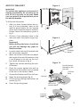
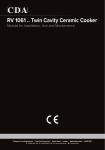
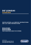
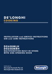
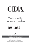
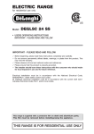
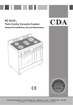
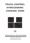
D E ’LON GHI
COOKING
INSTALLATION and SERVICE INSTRUCTIONS
USE and CARE INSTRUCTIONS
DEF905E
CERA M I C CO O K E R
distributed by
DeLonghi Australia Pty Ltd
DeLonghi New Zealand Ltd
Dear Customer,
Thank you for having purchased and given your preference to our product.
The safety precautions and recommendations reported
below are for your own safety and that of others. They will
also provide a means by which to make full use of the features offered by your appliance.
Please keep this booklet in a safe place. It may be useful
in future, either to yourself or to others in the event that
doubts should arise relating to its operation.
This appliance must be used only for the task it has
explicitly been designed for, that is for cooking foodstuffs. Any other form of usage is to be considered
as inappropriate and therefore dangerous.
The manufacturer declines all responsibility in the
event of damage caused by improper, incorrect or illogical use of the appliance or be faulty installation.
This appliance has been designed and constructed in accordance with the following codes
and specifications:
AS/NZS 60335.1
General Requirements for Domestic electrical appliances
AS/NZS 60335.2.6 Particular Requirements for Domestic electrical cooking appliances
AS/NZS CISPR 14.1 Electromagnetic Compatibility Requirements.
PRODUCT LABEL
2
Important:
This appliance is designed and manufactured solely for the cooking of domestic (household) food and is not suitable for any non
domestic application and therefore should not be used in a commercial environment.
The appliance guarantee will be void if the appliance is used within
a non domestic environment i.e. a semi commercial, commercial
or communal environment.
FIRST USE OF THE OVEN
It is advised to follow these instructions:
■■ Furnish the interior of the oven as described at chapters “USE
AND CARE” and “CLEANING AND MAINTENANCE”.
■■ Switch on the empty oven on max to eliminate grease from the
heating elements.
■■ Let the oven cool down and clean the interior of the oven with a
cloth soaked in water and neutral detergent, then dry carefully.
IMPORTANT PRECAUTIONS AND RECOMMENDATIONS FOR
USE OF ELECTRICAL APPLIANCES
Use of any electrical appliance implies the necessity to follow a series of fundamental rules. In particular:
■■ Never touch the appliance with wet hands or feet.
■■ Do not operate the appliance barefooted.
■■ The appliance is not intended for use by young children or infirm
persons without supervision.
■■ Young children should be supervised to ensure they do not play
with the appliance.
The manufacturer cannot be held responsible for any damages caused by improper, incorrect or illogical use of the appliance.
3
IMPORTANT PRECAUTIONS AND RECOMMENDATIONS
After having unpacked the appliance, check to ensure that it is not
damaged and that the oven door closes correctly. In case of doubt,
do not use it and consult your supplier or a professionally qualified
technician.
Packing elements (i.e. plastic bags, polystyrene foam, nails, packing
straps, etc.) should not be left around within easy reach of children,
as these may cause serious injuries.
■■ Some appliances are supplied with a protective film on steel and
aluminium parts. This film must be removed before using the
appliance.
■■ Do not attempt to modify the technical characteristics of the appliance as this may become dangerous to use.
■■ Do not carry out cleaning or maintenance operations on the appliance without having previously disconnected it from the electric power supply.
■■ After use, ensure that the knobs are in the off position.
■■ Keep children away from the appliance when it is in use.
■■ WARNING: Accessible parts will become hot when in use. To
avoid burns and scalds, young children should be kept away.
■■ Young children should be supervised to ensure that they do not
play with the appliance.
■■ Children, or persons with a disability which limits their ability to use
the appliance, should have a responsible person to instruct them
in its use. The instructor should be satisfied that they can use the
appliance without danger to themselves or their surroundings.
■■ During and after use of the appliance, certain parts will become
very hot. Do not touch hot parts. Care should be taken to avoid
touching heating elements inside the oven.
■■ Make sure that electrical cables connecting other appliances in
the proximity of the cooker cannot come into contact with the hob
or become entrapped in the oven door.
■■ Do not allow heavy or sharp objects to drop on the glass ceramic hob. If the hob is cracked or otherwise damaged by falling
objects etc., disconnect the electrical power cord and call Customer Service.
4
■■ Do not scratch the hob with sharp objects. Don’t use the hob as
a work surface.
■■ WARNING: When correctly installed, your product meets all safety requirements laid down for this type of product category.
However special care should be taken around the rear or the
underneath of the appliance as these areas are not designed or
intended to be touched and may contain sharp or rough edges,
that may cause injury.
■■ Do not line the oven walls with aluminium foil. Do not place baking trays or the drip tray on the base of the oven chamber.
■■ Fire risk! Do not store flammable material in the oven or in the
storage compartment.
■■ Always use oven gloves when removing the shelves and food
trays from the oven whilst hot.
■■ Do not hang towels, dishcloths or other items on the appliance or
its handle – as this could be a fire hazard.
■■ Clean the oven regularly and do not allow fat or oils to build up in
the oven base or tray. Remove spillages as soon as they occur.
■■ Do not stand on the open oven door.
■■ Always stand back from the appliance when opening the oven door
to allow steam and hot air to escape before removing the food.
■■ Safe food handling: Leave food in the oven for as short a time
as possible before and after cooking. This is to avoid contamination by organisms which may cause food poisoning. Take particular care during warmer weather.
■■ The manufacturer declines all liability for injury to persons or damage to property caused by incorrect or improper use of the appliance.
■■ WARNING: Taking care NOT to lift the oven by the door
handle.
■■ IMPORTANT NOTE: This appliance shall not be used as a
space heater, especially if installed in marine craft or caravans.
■■ Do not operate your appliance by means of an external timer
or separate remote-control system.
■■ This appliance is for domestic use only.
5
INSTALLATION
CAUTION:
■■
This appliance must be installed in accordance with these installation instructions.
■■
This appliance shall only be serviced by authorised personnel.
■■
This appliance is to be installed only by an authorised person in compliance
with the current electrical regulations and in observation of the instructions
supplied by the manufacturer.
Failure to comply with this condition will render the guarantee invalid.
■■
Incorrect installation, for which the manufacturer accepts no responsibility, may
cause personal injury of damage.
■■
Always disconnect the appliance from mains power supply before carrying out
any maintenance operations or repairs.
LOCATION
■■
The cooker can be installed in a cabinet (Fig. 1).
■■
The cooker must be installed no less than 50 mm away from any side wall which
exceed the height of the cooktop.
■■
The appliance must be housed in heat resistant units.
■■
The walls of the units must be capable of resisting temperatures of 75 °C above
room temperature.
■■
Do not install the appliance near inflammable materials (eg. curtains).
■■
If you stand the cooker on a pedestal, make sure you provide safety measures
to keep it in place.
6
450 mm
650 mm
5 0 mm
5 0 0 mm
Figure 1
Cooker overall dimensions [mm]
■■ height: min 900 - max 925
■■ width: 900
■■ depth: 600
7
FITTING THE ADJUSTABLE FEET
The adjustable feet must be fitted to the base of the cooker before use (fig. 2).
Rest the rear of the cooker on a piece of the polystyrene packaging exposing the base for
the fitting of the feet.
Fit the no. 4 (four) legs by screwing them tight into the support base as shown in figure 3.
LEVELLING THE COOKER
The cooker may be levelled by screwing the lower ends of the feet IN or OUT (fig. 4).
Figure 2
MOVING THE COOKER
Figure 3
Figure 4
Figure 5
WARNING: When raising cooker to upright
position always ensure two people carry
out this manoeuvre to prevent damage to
the adjustable feet (fig. 5).
WARNING - Be carefull: Do not lift the cooker by the door handle when raising to the
upright position (fig. 6).
WARNING: When moving cooker to its final position DO NOT DRAG (fig. 7). Lift feet
clear of floor (fig. 5).
Figure 6
8
Figure 7
ANTI-TILT BRACKET
Figure 8
Important!
To restrain the appliance and prevent it
tipping accidentally, fit a bracket to its
rear to fix it securely to the wall. Make
sure you also fit the supplied lock pin to
the anti-tilt bracket.
900 mm
900 mm
To fit the anti-tilt bracket:
2. Drill two 8 mm diameter holes in the
wall and insert the plastic plugs supplied.
450
0
+ 25
Figure 9
0
+ 25
Important!
Before drilling the holes, check that
you will not damage any pipes or
electrical wires.
Pivoting
panel
Pivoting
Anti-tiltpanel
bracket
3. Loosely attach the anti-tilt bracket with
the two screws supplied.
4. Move the cooker to the wall and adjust
the height of the anti-tilt bracket so that
it can engage in the slot on the cooker’s back, as shown in fig. 8.
5. Tighten the screws attaching the antitilt bracket.
6. Push the cooker against the wall so
that the anti-tilt bracket is fully inserted
in the slot on the cooker’s back.
7. Access the bracket and fit the lock pin:
■■
Open the pivoting panel (fig. 9).
■■
Fit the lock pin through the bracket, as
shown (fig. 10).
■■
Close the pivoting panel.
450
max 245
0
+ 25
min 220
max 245
1. After you have located where the cooker is to be positioned, mark on the
wall the place where the two screws
of the anti-tilt bracket have to be fitted.
Please follow the indications given in
fig. 8.
450
min 220
max 245
900 mm
450
(depending on feet adjustment)
450
(depending on feet adjustment)
min 220
(depending on feet adjustment)
450
attached on the
rearPivoting
wall
1
panel
Cooker’s
back
Lock pin
Figure 10
1
1
Lock pin
Slot on the
cooker’s back
2
Anti-tilt bracket
attached on the
rear bracket
wall
Anti-tilt
attached on the
rear wall Cooker’s
back
Cooker’s
back
Lock pin
Lock pin
correctly Slot on the
fitted
cooker’s back
2
Slot on the
cooker’s back
2
Lock pin
Lock
pin
correctly
correctly
fitted
fitted
9
ELECTRICAL REQUIREMENTS
■■
The appliance must be connected to the mains checking that the voltage corresponds to the value given in the rating plate and that the electrical cable sections can
withstand the load specified on the plate.
■■
A suitable disconnection switch must be incorporated in the permanent wiring, mounted
and positioned to comply with the local wiring rules and regulations. The switch must
be of an approved type installed in the fixed wiring and provide a 3 mm air gap contact
separation in all poles in accordance with the local wiring rules.
In Australia and New Zealand, a switch of the approved type with a 3 mm air gap must
be installed in the active (phase) conductor of the fixed wiring.
■■
The switch must always be accessible.
■■
The power supply cable must not touch the hot parts and must be positioned so that it
does not exceed 75°C above ambient.
■■
To connect the cooker to the mains electricity supply, do not use adapters, reducers or
branching devices as they can cause overheating and burning.
■■
This cooker must be connected to a suitable double pole control unit adjacent to the
cooker. No diversity can be applied to this control unit.
■■
This cooker must be connected to electrical supply using V105 insulated cable.
In New Zealand, this appliance must be connected to the electrical supply using a
cable fitted with an appropriately rated plug. The plug must be compatible with the
socket-outlet fitted to the final subcircuit in the fixed wiring that is intended to supply
the appliance.
■■
Once the appliance has been installed, the switch or socket must always be accessible.
■■
If the supply cord is damaged it must be replaced by the manufacturer or it’s Service
Agent or a similarly qualified person in order to avoid a hazard.
N.B. The connection of the appliance to earth is mandatory.
If the installation requires alterations to the domestic electrical system call a qualified electrician. He should also check that the domestic electrical system is suitable for the power
drawn by the appliance.
Replacing the power cord must be done by a qualified electrician in accordance with
the instructions supplied by the manufacturer and in compliance with established
electrical regulations.
10
LOCATING THE AREA FOR ELECTRICAL CONNECTION
ELECTRIC CONNECTION
Dotted line
showing the
position of the
cooker when
installed
max 290 mm
Area for ELECTRIC
connection
Figure 11
11
CONNECTION OF THE POWER SUPPLY CABLE
Important! This cooker must be connected to the electricity supply only by an authorised person.
To connect the feeder cable to the cooker it is necessary to:
•
Remove the two screws that hold shield “A” behind the cooker (fig. 12).
•
Open completely the cable clamp “D”.
•
Fitted with a 6-pole terminal block, position the U bolts onto terminal block ‘B’ (fig. 12)
according to the diagrams in figs. 13 - 14.
•
Feed the supply cable through the cable clamp “D”. The supply cable must be of a
suitable size for the current requirements of the appliance; see the section “Feeder
cable section”.
•
Connect the phase, neutral and earth wires to terminal “B” according to figures 13 and
14.
•
Pull the feeder cable and block it with the cable clamp “D”.
•
Re-mount shield “A”.
N.B. The earth conductor must be left about 3 cm longer than the others.
VOLTAGE AND POWER CONSUMPTION
230/400 V 3N~
50 Hz
11800 W (51.30 A) (diversity not applied)
240/415 V 3N~
50 Hz
12800 W (53.33 A) (diversity not applied)
FEEDER CABLE SECTION
This cooker must be connected to electrical supply using V105 insulated cable.
230 V~, 240 V~
3 x 6 mm2 (*)
230 V 3~, 240 V~
4 x 4 mm2 (*)
400 V 3N~, 415 V 3N~
5 x 2,5 mm2 (*)
400 V 2N~, 415 V 2N~
4 x 4 mm2 (*)
(*)
Connection with wall box connection.
–– Diversity factor applied.
–– A diversity factor may be applied to the total loading of the appliance only by a
suitably qualified person.
12
Figure 12
Figure 13
230 V~
230 V~, 240 V~
1 2 3 4 5
B
L1
N (L 2) PE
D
230 V 3~
230 V 3~, 240 V 3~
A
1
2
3
L1
4
5
1
N(L 2)
PE
2
3
L1
230 V~
230 V~,
240 V~
4
L2
1 2 3 4 5
PE
3~ V 3~
230 V 230
3~,V240
L 2 L 3 PE
L1
5
L3
400 V 3N~
400 V 3N~, 415 V 3N~
1 2 3 4 5
1
2
3
4
5
N
L2
L1
PE
L1 L2 L3
N PE
400 V 415
2N~ V 2N~
400 V 2N~,
400 V 2N~
400 V 2N~, 415 V 2N~
1
L1
2
L2
3
4
L3
1 2 3 4 5
5
N
PE
L1
Figure 14
L2
N PE
400 V 3N~,
400 V415
3N~V 3N~
13
14
1a
1
PR
L/8
N/7
S1
P2
P1
P3
S
V
G
C
3
4
1
2
5
F1
CF
LF
TL
TM
M
S2
2 SH
1
S1
2
3
4
5
S2
2
SH
P2
4
PILOT
S1
P2
T
4a
2 SH
P3
4
S2
4A
S1
P2
CR
2
P2
F4
P1
2
4
F3
P1
2
4
F2
P1
P1
4
PILOT
4
S2
2
4
4a
S H
S2
4
4a
F5
S1
P2
2
P4
P1
S2
2
SH
S1
P2
2
F6
P1
P5
4
PILOT
4
ELECTRIC DIAGRAM
Figure 15
ELECTRIC DIAGRAM KEY
P1/2/5 Hob single zones elements
P3
Hob double zone (oval) element
P4
Hob double zone element
F2/3/6 Energy regulators (single zones)
F4/5
Energy regulators (double zones)
F1
Oven switch
TM
Oven thermostat
LF
Oven lamp
PROven programmer
CFCooling fan motor
V
Oven fan motor
C
Oven top element
G
Oven grill element
S
Oven bottom element
TLThermal overload
S1Thermostat pilot lamp
S2Hob elements pilot lamp
CRHob elements residual heat lamps
M
Terminal block
T
Earth connection
15
USE AND CARE
CAUTION:
■■
■■
This appliance must be used only for the task it has explicitly been designed for, that
is for domestic cooking of foodstuffs. Any other form of usage is to be considered as
inappropriate and therefore dangerous.
Do NOT place combustible materials or products on this appliance at any time.
Figure 16
USING THE OVEN FOR THE FIRST
TIME
Operate as follows:
■■ Slide in the wire racks on the oven
walls as in fig. 16.
■■
■■
Slide in the grease filter on the back of
the oven as in fig. 19.
Slide into the guides, the shelf and the
tray (fig. 17).
The rack must be fitted so that the safety notch, which stops it sliding out,
faces the inside of the oven; the guard
rail shall be at the back.
The oven tray must be correctly placed
on its wire shelf support (fig. 18) then
inserted into the guides (fig. 17). The
oven tray shelf support must be fitted
so that the safety notch, which stops it
sliding out, faces the inside of the oven
■■
To eliminate traces of grease in manufacture it is necessary to pre-heat the
oven at the maximum temperature:
position
• For 60 minutes in the
and for another 15 minutes in the
position.
■■
Slide off the wire racks.
■■
Let the oven cool down, switch off the
electrical supply, then clean the inside
of the oven with a cloth soaked in water and neutral detergent and dry thoroughly.
16
G
Figure 17
Guard rail
Stop notch
Stop notch
Figure 18
GREASE FILTER
■■
A special screen is provided at the back of the oven to catch grease particles, mainly
when meat is being roasted.
■■
Clean the filter after any cooking! The grease filter can be removed for cleaning and
should be washed regularly in hot soapy water (fig. 19).
■■
Always dry the filter properly before fitting it back into the oven.
CAUTION: When baking pastry etc. this filter should be removed.
Figure 19
17
CONTROL PANEL
Figure 20
10
8
7
9
6
5
4
3
2
1
Controls description
1. Front right cooking zone control knob
2. Rear right cooking zone control knob
3. Central cooking zone control knob
4. Rear left cooking zone control knob
5. Front left cooking zone control knob
6. Oven temperature control knob
7. Oven function selector control knob
8. Electronic programmer
Pilot lamps:
9. Cooking zone/s ON indicator light
10. Oven temperature indicator light
Please note:
This appliance incorporates a safety cooling fan which you will hear operating whenever
the oven or grill are in use.
This fan is to reduce the external temperature of the appliance and cool the internal components.
18
OB
VITROCERAMIC HOB
Figure 21
4
2
3
1
5
6
VITROCERAMIC COOKING HOB
1. “Hi-Light” single zone, Ø 180 mm 1800 W
2. “Hi-Light” single zone, Ø 145 mm 1200 W
3. “Hi-Light” double zone (oval), Ø 145 x 250 mm 2000/1100 W
4. “Hi-Light” double zone, Ø 210/120 mm
2200/750 W
5. “Hi-Light” single zone, Ø 145 mm 1200 W
6. Cooking zones residual heat indicators
Attention:
Detach the appliance from the mains if the ceramic glass is cracked and contact the AfterSales Service.
Metallic objects such as knives, forks, spoons and lids should not be placed on the hob
surface since they can get hot.
19
HOW TO USE THE VITROCERAMIC HOB
The ceramic surface of the hob allows a fast transmission of heat in the vertical direction,
from the heating elements underneath the ceramic glass to the pans set on it.
The heat does not spread in a horizontal direction, so that the glass stays “cool” at only a
few centimeters from the cooking plate.
The cooking zones are shown by painted disks on the ceramic surface.
Before switching on the cooktop make sure that it is clean.
Important note:
The heating elements incorporate a thermolimiter that switches the element ON/OFF during all settings to protect the ceramic glass from overheating.
The use of incorrect pans and/or wrong pan positioning will cause the temperature limiter
to operate more frequently, resulting in a reduction of cooking performance.
The temperature limiter can be seen under the glass dissecting the element. This is not a
fault with the appliance.
“Hi-Light” SINGLE ZoneS (fig. 23)
■■
■■
■■
■■
The heating element is formed of a coil of resistant material which reaches the working
temperature quickly.
These zones are controlled by a continuous energy regulator switch (fig. 22). The heat
intensity can be regulated continuously from “0” to “12” (max).
Check that the hob is clean and then switch on by turning the control knob.
When the hob is working, the power on indicator light will be on.
Figure 22
20
Figure 23
“Hi-light” double zoneS (figs. 25, 26)
■■
The heating element is formed of 2 coils of resistant material which reaches the working temperature quickly.
■■
This zone is controlled by a continuous energy regulator switch (fig. 24). The heat
intensity can be regulated continuously from “0” to “12” (max).
■■
Check that the hob is clean and then switch on by turning the control knob.
■■
When the hob is working, the power on indicator light will be on.
■■
To turn on both zones of the double element, turn the double element knob fully
.
clockwise to the position
To reduce the heat of the full double element, turn its knob anticlockwise to setting “12”
or lower. Adjust the heat during cooking as necessary.
■■
Note: if you leave the knob at the
position, the full double element will remain at the highest heat setting.
Figure 24
To return to using only the inner zone of
the double element, first turn the knob
to the “0“ (off) position (you should feel
a click) and then clockwise to a setting
from “1” to “12”.
Figure 25
Second element
DOUBLE ZONE
Figure 26
Second element
DOUBLE ZONE (OVAL)
21
SAFETY HINTS
1. Never put cooking foil or plastic materials on the ceramic surface when the hob is hot.
2. Make sure that the hob is clean before you use it.
3. Always ensure that the base of your saucepan is clean and dry before placing on the
hob.
4. The glass-ceramic surface and pans must be clean. Carefully eliminate any food remains (especially containing sugar), dirt etc. with the aid of a cleansing agent.
5. Remember that the plates will remain hot for approximately half an hour after the plate
has been switched off.
6. Before you switch the hob on, make sure that you know which knob controls the required hot plate. We advise you to set the pan over the cooking plate before switching
it on.
7. Pan handles should never stand out beyond the kitchen worktop, as there is a great
danger of knocking the pan over. This will also ensure that children cannot reach them.
8. Do not use pots and pans with rough bases (pay attention to cookware made of castiron). Rough bases can damage the glass surface of the hob (scratches).
9. Pots with aluminium bottoms may leave silver streaks or spots on the hob.
10. DO NOT use the hob if the glass surface is broken or cracked in any way.
Please disconnect the appliance from the mains and call the After-Sales Service.
11. Do not lean over the cooking plate when in use.
12. Do not leave wet or damp lids on the hob.
13. Follow the cleaning instructions carefully.
14. Never use the glass surface for storage.
WARNING:
■■ HOBS BECOME VERY HOT WITH USE, AND RETAIN THEIR HEAT FOR A LONG
TIME AFTER COOKING HAS FINISHED. CHILDREN SHOULD BE SUPERVISED
AT ALL TIMES AND BE PREVENTED FROM TOUCHING THE HOT SURFACES
UNTIL SUCH TIME AS THE APPLIANCE HAS COOLED.
Figure 27
Figure 28
DO NOT USE GLASS WARE ON CERAMIC HOBS.
DO NOT USE PANS WITH ROUGHT CIRCULAR
MACHINED BASE.
22
RESIDUAL HEAT INDICATORS
The hob also features no. 6 (six) warning
lights which are connected to the corresponding plates.
When the temperature of a cooking plate is
above 60°C, the relevant warning light will
also light up to warn of heat on the surface
of the hob.
This light also stay on after the cooking plate has been switched off to show that the
hob surface is still hot.
This residual heat will lasts for a long time
after the cooking plate has been switched off.
During this time you should avoid touching the hob surface over the cooking
area.
Please pay special attention to ensure
that children are not allowed near the
hob.
The light will switch off automatically as
soon as the surface temperature of the cooking plate falls below 60°C.
Figure 29
Caution!
The cooking hob becomes very hot
during operation.
Keep children well out of reach.
COOKING HINTS
■■
■■
■■
To reduce the cooking time, you can turn the control knob to the max when you switch
the plate on.
After a short time you will set the control knob to the required position for the cooking.
You should use pots and pans with flat bases (pans with the test mark for glass ceramic hobs are available from specialist shops).
The diameter of the pan should match that of the cooking plate (or be slightly bigger)
to make the most of the energy.
Since the cooking surface stays hot for a certain time after the plate has been switched
off, you can switch it off 5 or 10 minutes before the end of the cooking.
The residual heat of the hob will complete the cooking.
■■
To save electricity, use pan lids whenever possible.
■■
Never cook the food directly on the glass ceramic cooktop, but in special pans
or containers.
■■
Do not scratch the cooktop with cutting or sharp objects. Do not use the glass
ceramic surface as a work surface.
23
Elements usage table
Figure 30
Knob
setting
COOKING HINTS:
Temperature control knob
2
3
Warming
1
4
6
7
Cooking
5
8
10
11
12
■■
Roasting - Frying
9
TYPE OF COOKING
0
Switched OFF
1
2
For melting operations (butter, chocolate).
2
3
4
To maintain food hot and to
heat small quantities of liquid
(sauces, eggs).
4
5
6
To heat bigger quantities;
to whip creams and sauces
(vegetables, fruits, soups).
6
7
Slow boiling, i.e.: boiled meats, spaghetti, soups, continuations of steam cooking of
roasts, stews, potatoes.
7
8
For every kind of frying,
cutlets, uncovered cooking,
i.e.: risotto.
8
9
10
Browning of meats, roasted
potatoes, fried fish, omelettes, and for boiling large
quantities of water.
11
12
Fast frying, grilled steaks,
etc.
Switching on the second element (double zones only)
Please note that these are only guidelines, you will quickly learn from experience
which setting is correct for your needs.
ECONOMIC COOKING
■■
The ceramic glass retains heat, so you may find that you can switch off the heat 5
minutes before you finish cooking.
■■
To reduce the cooking time, the plate can be set to the maximum setting at the beginning. It can then be reduced later.
24
COOKWARE:
It is very important that the pans used on the hobs are made of a suitable material and have
the correct base as follows:
■■
The base should be flat and smooth.
■■
Any rough part on the pan base could scratch the hob surface.
■■
Choose pans which are the same size as the hotplates and with bases that are as non
reflective as possible. eg. dull and dark.
Only pans recommended for use on ceramic hobs should be used.
Pans made of the following materials can cause problems:
Cast Iron
■■
The base may be rough which will scratch the hob.
Toughened Glass
■■
If the pans become too hot, the hob may overheat causing
the safety cut out to operate too frequently thus reducing the
cooking efficiency.
Copper
■■
Can easily distort and will therefore not form a good contact
between base and hob which will result in uneven cooking.
25
COOKING WITH FAN ASSISTED OVEN
Attention: The oven door becomes
very hot during operation.
Keep children away.
GENERAL FEATURES
As its name indicates, this is an oven that
presents particular features from an operational point of view.
In fact, it is possible to insert 4 different programs to satisfy every cooking need.
The 4 positions, thermostatically controlled, are obtained by 4 heating elements
which are:
■■
Bottom element 2050 W
■■
Top element 1250 W
■■
Grill element 2200 W
OPERATING PRINCIPLES
Heating and cooking in the fan assisted
oven are obtained in the following ways:
a. by normal convection
The heat is produced by the upper and
lower heating elements.
b. by semi-forced convection
The heat produced by the upper and
lower heating elements is distributed
throughout the oven by the fan.
c. by radiation
The heat is irradiated by the infra red
grill element.
d. by radiation and ventilation
The irradiated heat from the infra red
grill element is distributed throughout
the oven by the fan.
e. by ventilation
The food is defrosted by using the fan
only function without heat.
WARNING:
The door is hot, use the handle.
During use the appliance becomes
hot. Care should be taken to avoid
touching heating elements inside the
oven.
26
Figure 31
THERMOSTAT KNOB
To turn on the heating elements of the oven, set function selector knob to the required position and the thermostat knob to the desired temperature.
To set the temperature, turn the thermostat control knob indicator mark to the required
temperature.
The elements will turn on or off automatically which is determined by the thermostat.
The operation of the heating elements is signalled by a light placed above the knob.
FUNCTION SELECTOR KNOB
Rotate the knob clockwise to set the oven for one of the following functions:
OVEN LIGHT
By turning the knob onto this setting we light the oven cavity.
The oven remains alight while any of the functions is on.
TRADITIONAL CONVECTION COOKING
The upper and lower heating elements are switched on. The heat is diffused by natural convection and the temperature must be regulated between 50°C and the maximum position
with the thermostat knob.
It is necessary to preheat the oven before introducing the foods to be cooked.
Recommended for:
For foods which require the same cooking temperature both internally and externally, i. e.
roasts, spare ribs, meringue, etc.
27
CONVECTION COOKING WITH VENTILATION
The upper and lower heating elements and the fan turn on.
The heat coming from the top and bottom is diffused by forced convection.
The temperature must be regulated between 50°C and the maximum position with the thermostat knob.
Recommended for:
For foods of large volume and quantity which require the same internal and external
degree of cooking; for ie: rolled roasts, turkey, legs, cakes, etc.
DEFROST
With the thermostat knob on “0” only the oven fan is on.
The food is thawed by ventilation without heating.
Recommended for:
Quick thawing of frozen foods; one kg requires approximately 1 hour.
Thawing times vary according to the quantity and type of food to be thawed.
VENTILATED GRILL COOKING
The infra-red grill and the fan are on. The heat is mainly diffused by radiation and the fan then
distributes it throughout the oven.
Use with the oven door closed and the thermostat knob must be regulated between 50°C
and 200°C maximum.
It is necessary to preheat the oven for about 5 minutes.
For correct use see chapter “GRILLING AND AU GRATIN”.
Always grill with the oven door closed.
Recommended for:
For grill cooking when a fast outside browning is necessary to keep the juices in, i. e. veal
steak, steak, hamburger, etc.
GRILLING
The infra-red heating element is switched on.
The heat is diffused by radiation.
Use with the oven door closed and the thermostat knob to position 225 °C for max 15
minutes, then to position 175 °C.
For correct use see chapter “USE OF THE GRILL”.
Always grill with the oven door closed.
Recommended for:
Intense grilling, browning, cooking au gratin and toasting etc.
28
COOKING ADVICE
The external parts of the appliance become hot during operation.
Keep children well out of reach.
OVEN COOKING
To cook, before introducing the food, preheat the oven to the desired temperature.
When the oven has reached the desired temperature, introduce the food, control the cooking
time and tum off the oven 5 minutes before the theoretical time to recuperate the stored heat.
STERILIZATION
Sterilization of foods to be conserved, in full and hermetically sealed jars, is done in the
following way:
a. Set the switch to position
.
b. Set the thermostat knob to position 175 °C and preheat the oven.
c. Fill the dripping pan with hot water.
d. Set the jars onto the dripping pan making sure they do not touch each other and the door
and set the thermostat knob to position 130 °C.
When sterilization has begun, that is, when the contents of the jars start to bubble, turn off
the oven and let cool.
REGENERATION
Set the switch to position
and the thermostat knob to position 150° C.
Bread becomes fragrant again if wet with a few drops of water and put into the oven for
about 10 minutes at the highest temperature.
ROASTING
To obtain classical roasting, it is necessary to remember:
■■
that it is advisable to maintain a temperature between 180 and 200 °C.
■■
that the cooking time depends on the quantity and the type of foods.
COOKING DIFFERENT DISHES AT THE SAME TIME
The fan assisted oven set on position
gives simultaneous heterogeneous cooking of
different foods.
Different foods such as fish, cake and meat can be cooked together without mixing the
smells and flavours.
This is possible since the fats and vapors are oxidized while passing through the electrical
element and therefore are not deposited onto the foods.
The only precautions to follow are:
■■
The cooking temperatures of the different foods must be as close to as possible, with
a maximum difference of 20° - 25 °C.
■■
The introduction of the different dishes in the oven must be done at different times in
relation to the cooking times of each one.
The time and energy saved with this type of cooking is obvious.
29
USE OF THE GRILL
Preheat the oven for about 5 minutes.
Introduce the food to be cooked, positioning the rack as close to the grill as possible.
The dripping pan should be placed under the rack to catch the cooking juices and fats.
Grilling with the oven door closed.
Do not grill for longer than 30 minutes at any one time.
ATTENTION: the oven door becomes very hot during operation. Keep children away.
GRILLING AND “AU GRATIN”
Grilling may be done using the grill+fan setting
, in this setting the hot air completely
surrounds the food that is to be cooked, to give a more even and rapid cooking process.
Set the temperature knob between 50°C and 200°C maximum, preheat the oven, then
simply place the food on the grid.
Close the door until grilling is complete.
Adding a few dabs of butter before the end of the cooking time gives the golden “au gratin”
effect.
Grilling with the oven door closed.
Do not grill for longer than 30 minutes at any one time.
ATTENTION: the oven door becomes very hot during operation. Keep children away.
30
RECOMMENDED COOKING TEMPERATURE
Food
°C
°F
Gas
Mark
Shelf
Position*
Cooking
Time (approx)
190
375
5
2 or 3
20-25 mins
CAKES
Victoria sandwich
Small cakes/buns
190
375
5
1 and 2
15-20 mins
Maidera cake
180
350
4
2 or 3
20 mins
Fruit cake
170
325
3
3
13/4 hours
Rich fruit cake
150
300
2
3 or 4
21/2 hours
Scones
225
425
8-9
2
8-10 mins
Puff
225
425
8-9
2
10-20 mins
Short crust
200
400
6
2
20-30 mins
Plate tarts
200 - 210
400 - 410
6
1 or 2
30-35 mins
Quiches and flans
200 - 210
400 - 410
6
1 or 2
40-45 mins
Bread loaf
225
425
7-8
2
35-55 mins
Bread rolls
220
425
7
1 or 2
15-20 mins
Pizza dough
230
450
8
2
20 mins
Beef – Medium
190
375
5
2 or 3
20 mins/lb + 20 mins
Lamb
190
375
5
2 or 3
25-30 mins/b + 25 mins
Pork
190 - 200
375 - 400
5-7
2 or 3
30 mins/lb + 30 mins
Veal
190
375
5
2 or 3
30 mins/b + 30 mins
Chicken
190
375
5
2 or 3
30 mins/b + 30 mins
PASTRY
YEAST
ROAST MEAT
Turkey up to 10lb
180
350
4
2 or 3
18-20 mins/b + 20 mins
Stews/casseroles
150 - 170
300 - 325
2-3
2 or 3
11/2 2 hours
N.B. For fan ovens reduce the temperature
by 10-20°C. For any dish taking one hour
or over to cook, reduce the cooking time by
10 minutes per hour.
* Shelf positions have been counted from
the top of the oven to the base.
A fan oven creates more even temperature throughout, therefore the shelf positions
are not as critical.
31
DIGITAL ELECTRONIC PROGRAMMER
The electronic programmer is a device which groups together the following functions:
■■
24 hours clock with illuminated display.
■■
Timer (up to 23 hours and 59 minutes).
■■
Program for automatic oven cooking.
■■
Program for semi-automatic oven cooking.
Description of the buttons:
Timer
Cooking time
End of cooking time
Manual position and cancellation
of the inserted cooking programme
To increase the numbers on the
digital display
To decrease the numbers on the
digital display and changing the
frequency of the audible signal
Figure 32
32
Description
symbols:
of
the
illuminated
AUTO - flashing - Programmer in automa-
tic position but not programmed
AUTO - illuminated - Programmer in auto-
matic position with program inser-
ted.
Automatic cooking taking place
Timer in operation
and AUTO - flashing - Program error.
(The time of day lies between the calculated cooking start and end time).
Note:
Select a function by the respective button
and, in 5 seconds, set the required time
with the
/
buttons (“one-hand”
operation).
After a power cut the display resets to zero
and cancels the set programs.
Figure 33
ELECTRONIC CLOCK (fig. 33)
ELECTRONIC TIMER
The programmer is equipped with an electronic clock with illuminated numbers which
indicates hours and minutes.
Upon immediate connection of the oven or
after a power cut, three zeros will flash on
the programmer display.
To set the correct time of day it is necessary to push the
button and then the
or
button until you have set the correct
time (fig. 29).
In another way push simultaneously the
two buttons and at the same time
push the
or
button.
The timer program consists only of a buzzer which may be set for a maximum period
of 23 hours and 59 minutes.
If the AUTO symbol is flashing push the
button.
To set the time, push the
button and
the
or
until you obtain the desired
time in the display (fig. 35).
Having finished the setting, the clock hour
will appear on the panel and the
symbol
will be illuminated.
The countdown will start immediately and
may be seen at any moment on the panel
by simply pressing the button
.
At the end of the time, the
symbol will
disappear and the buzzer will sound and
continue for approximatley 7 minutes or
until a button is pressed (not the
/
buttons). After a short time the display will
revert back to the time of day.
Note: If the clock is reset it deletes any previously set programs
NORMAL COOKING WITHOUT THE
USE OF THE PROGRAMMER
To manually use the oven, without the aid
of the programmer, it is necessary to cancel the flashing AUTO by pushing the
button (AUTO will be switched off and the
symbol
will illuminate - Fig. 34).
Attention: If the AUTO is illuminated
(which means a cooking program has already been inserted), by pushing the button
you cancel the program and return to
manual operation.
If the oven is switched on, you must
switch off manually.
Figure 34
SETTING THE FREQUENCY OF THE
AUDIBLE SIGNAL
The buzzer has 3 different tones and can
be changed by pressing the
button,
but only when the time of day is displayed.
Figure 35
33
AUTOMATIC OVEN COOKING
To cook food automatically in the oven, it is
necessary to:
1. Set the length of the cooking period.
2. Set the end of the cooking time.
3. Set the temperature and the oven cooking program.
These operations are done in the following
way:
1. Set the length of the cooking period
button and the
by pushing the
button
to increase, or
to decrease if you have passed the desired
time (fig. 36). The AUTO and the
symbol will illuminate.
2. Set the end of the cooking time by pressing the
button (the cooking time
already added to the clock time will appear), and the
button (fig. 37); if
you pass the desired time you may get
back by pushing the
button.
After this setting, the
symbol
will disappear. If after this setting, the
AUTO flashes on the display and a
buzzer sounds, it means there was
an error in the programming, that is
that the cooking cycle has been superimposed on the clock. In this case,
modify the end of cooking time or the
cooking period itself by following again
the above mentioned instructions.
Figure 36
34
3. Set the temperature and the cooking
program by using the switch and thermostat knobs of the oven (see specific
chapters).
Now the oven is programmed and
everything will work automatically, that is
the oven will turn on at the right moment
to end the cooking at the established hour.
symbol remains
During cooking, the
illuminated.
By pushing the
button you can see the
time that remains until the end of cooking.
The cooking program may be cancelled
at any time by pushing
.
At the end of the cooking time the oven will
symbol will
turn off automatically, the
turn off, AUTO will flash and a buzzer will
sound, which can be turned off by pushing
any of the buttons except the
/
buttons.
Turn the switch and thermostat knobs to
zero and put the programmer onto “manual” by pressing the
button.
Attention: After a power cut the clock resets to zero and cancels the set programs.
After a power cut, three zeros will flash on
the display.
Figure 37
SEMI-AUTOMATIC COOKING
This is used to automatically switch off the
oven after the desired cooking time has
elapsed.
There are two ways to set your oven:
1. Set the length of the cooking time by
pushing the
button and the
button to advance, or
to go
backwards if you have passed the desired time (fig. 38).
or
2. Set the end of the cooking time by
pushing the
button and the
button to advance, or
to go
backwards if you have passed the desired time (fig. 39).
AUTO and the
At the end of the cooking time the oven will
symbol will
turn off automatically, the
turn off, AUTO will flash and a buzzer will
sound, which can be turned off by pushing
any of the buttons except the
/
buttons.
Turn the switch and thermostat knobs to
zero and put the programmer onto “manual” by pressing the
button.
Attention: After a power cut the clock resets to zero and cancels the set programs.
After a power cut, three zeros will flash on
the display.
symbol will be on.
Then set the temperature and the cooking
programme using the oven switch and
thermostat knobs (see specific chapters).
The oven is switched on and it will be
switched off automatically at the end of the
desired time.
symbol remains on
During cooking, the
you can
and by pressing the button
see the time that remains till the end of the
cooking.
The cooking program may be cancelled
at any time by pushing
.
Figure 38
Figure 39
35
CLEANING AND MAINTENANCE
GENERAL ADVICE
■■
■■
■■
■■
■■
■■
■■
Before you begin cleaning, you must ensure that the appliance is switched off
and disconnected from the electrical power supply.
It is advisable to clean when the appliance is cold and especially when cleaning the
enamelled parts.
Avoid leaving alkaline or acidic substances (lemon juice, vinegar, etc.) on the surfaces.
Avoid using cleaning products with a chlorine or acidic base.
Do not use a steam cleaner because the moisture can get into the appliance thus
make it unsafe.
Important: The use of suitable protective clothing/gloves is recommended when
handling or cleaning of this appliance.
Do not use harsh abrasive cleaners or sharp metal scrapers to clean the oven
door glass since they can scratch the surface, which may result in shattering of
the glass.
WARNING!
When correctly installed, your product meets all safety requirements laid down for
this type of product category. However special care should be taken around the rear
or the underneath of the appliance as these areas are not designed or intended to be
touched and may contain sharp or rough edges, that may cause injury.
ENAMELLED PARTS
All the enamelled parts must be cleaned with a sponge and soapy water or other nonabrasive products.
Dry preferably with a microfibre or soft cloth.
Acidic substances like lemon juice, tomato sauce, vinegar etc. can damage the enamel if
left too long.
STAINLESS STEEL, ALUMINIUM PARTS, PAINTED AND SILK-SCREEN PRINTED SURFACES
Clean using an appropriate product.
Always dry thoroughly.
IMPORTANT: these parts must be cleaned very carefully to avoid scratching and abrasion.
You are advised to use a soft cloth and neutral soap.
CAUTION: Do not use abrasive substances or non-neutral detergents as these will
irreparably damage the surface.
36
CLEANING THE CERAMIC HOB
■■
■■
■■
■■
■■
■■
■■
■■
■■
■■
■■
Figure 40
Remove spillages and other types of
incrustations.
Dust or food particles can be removed
with a damp cloth.
If you use a detergent, please make
sure that it is not abrasive or scouring.
Abrasive or scouring powders can damage the glass surface of the hob.
All traces of the cleaner must be removed with a damp cloth.
Dust, fat and liquids from food that has
boiled over must be removed as soon
as possible.
If they are allowed to harden they become increasingly difficult to remove.
This is especially true in the case of sugar/syrup mixtures which could permanently pit the surface of the hob if left to burn on it.
Keep all objects that could be melted by the heat away from the top: plastic objects,
aluminium foil, sugar or sugary products.
If any of these products has melted on the ceramic surface, you should remove it
immediately (when the surface is still hot) by using the scraper supplied with the appliance to avoid any permanent damage to the surface of the hob.
Avoid using a knife or other sharp utensil as these may damage the ceramic surface.
Do not use steel wool or an abrasive sponge which could scratch the surface permanently.
ATTENTION - MOST IMPORTANT!
If cleaning the glass ceramic hob using a special scraper tool take extra care to
avoid damaging the seal at the edges of the glass ceramic surface.
INSIDE OF OVEN
The oven should always be cleaned after use when it has cooled down.
The cavity should be cleaned using a mild detergent solution and warm water.
Suitable proprietary chemical cleaners may be used after first consulting with the manufacturers recommendations and testing a small sample of the oven cavity.
Abrasive cleaning agents or scouring pads/cloths should not be used on the cavity surface.
NOTE: The manufacturers of this appliance will accept no responsibility for damage caused by chemical or abrasive cleaning.
Do not store flammable material in the oven.
Let the oven cool down and pay special attention no to touch the hot heating elements inside the oven cavity.
37
GRILL HEATING ELEMENT
■■
The heating element is self-cleaning and does not require maintenance.
GREASE FILTER
Clean the filter after any cooking!
The grease filter can be removed for cleaning and should be washed regularly in hot soapy
water (fig. 19 at page 17). Always dry the filter properly before fitting it back into the oven.
OVEN FLOOR
Figure 41
The oven floor “F” (fig. 41) can be
easily removed to facilitate cleaning.
Remember to replace the floor correctly afterwards.
Be careful not to confuse the tray
“L” with the oven floor “F”.
STORAGE COMPARTMENT
The storage compartment is accessible through the pivoting panel (fig. 42).
L
F
Figure 42
Do not store flammable material in the storage
compartment.
REPLACING THE OVEN LIGHT
WARNING: Ensure the appliance
is switched off before replacing
the lamp to avoid the possibility
of electric shock.
■■ Let the oven cavity and the heating
elements to cool down.
■■ Switch off the electrical supply.
■■ Remove the protective cover “A”
(fig. 43).
■■ Replace the lamp “B” with a new
one suitable for high temperatures
(300°C) having the following specifications 220-240V or 230-240V,
50Hz, type E14 and same power
(check watt power as stamped in
the bulb itself) of the replaced lamp.
■■ Refit the protective cover “A”.
NOTE: Oven bulb replacement is not covered by your guarantee.
38
Figure 43
B
A
REMOVING AND REPLACING THE INNER DOOR GLASS PANE FOR CLEANING
If you wish to clean the inner glass of the door, make sure you follow the precautions and
instructions very carefully.
Replacing the glass pane and the door incorrectly may result in damage to the appliance
and may void your warranty.
IMPORTANT!
■■
Take care, the oven door is heavy. If you have any doubts, do not attempt to remove
the door.
■■
Make sure the oven and all its parts have cooled down. Do not attempt to handle the
parts of a hot oven.
■■
The internal glass panel can be easily removed for cleaning by unscrewing the 4 retaining screws (fig. 44).
■■
Take extreme care when handling the glass pane. Avoid the edges of the glass bumping against any surface. This may result in the glass shattering.
■■
CAUTION:
Do not use harsh abrasive cleaners or sharp metal scrapers to clean the oven door
glass since they can scratch the surface, which may result in shattering of the glass.
■■
If you notice any sign of damage on any of the glass panes (such as chipping, or
cracks), do not use the oven. Call your Authorised Service Centre or Customer Care.
■■
Make sure you replace the glass pane correctly. Do not use the oven without glass
pane correctly in place.
■■
If the glass pane feels difficult to remove or replace, do not force it. Call your Authorised Repairer or Customer Care for help.
Note: service visits providing assistance with using or maintaining the oven are not
covered by your warranty.
Figure 44
39
REMOVING THE OVEN DOOR
The oven door can easily be removed as follows:
■■
Open the door to the full extent (fig. 45a).
■■
Attach the retaining rings to the hooks on the left and right hinges (fig. 45b).
■■
Hold the door as shown in fig. 45c.
■■
Gently close the door and withdraw the lower hinge pins from their location (fig. 45d).
■■
Withdraw the upper hinge pins from their location (fig. 45e).
■■
Rest the door on a soft surface.
■■
To replace the door, repeat the above steps in reverse order.
Figure 45a
Figure 45b
Figure 45c
Figure 45d
40
Figure 45e
Service and Maintenance
SERVICING THE APPLIANCE
Service may be obtained by contacting our Customer Service Centre to locate the nearest
Authorised Delonghi Service Agent:
Servicing shall be carried out only by authorized personnel.
The appliance shall not be modified.
TROUBLESHOOTING
If you experience a problem with your oven, check the following points before calling our
Customer Service Centre for assistance.
1. The power is switched on.
2. The controls are switched on.
3. Oven only: you have set the clock of the electronic programmer (the oven will not work
until this has been done).
4. Oven only: none semi-automatic or automatic cooking program has been selected.
5. Both the fuse and the mains fuse are intact.
Should you still require assistance please contact our Customer Service Centre for your
nearest Authorised Delonghi Service Agent.
41
42
43
Desc ri ptio n s an d illu st r ations in this book let ar e gi v e n a s s i m p l y i n d i c a t i v e .
The man u f actu rer res er ves the r ight, cons ider in g t h e c h a ra c t e r i s t i c s o f t h e
model s described h e re, at any tim e and w ithout notic e , t o m a k e e v e n t u a l n e c e s s a r y
modifi c atio n s fo r th e ir cons tr uction or for com m er c i a l n e e d s .
w w w. de lo nghi. co m . au
w w w.de lo nghi. co . nz
Cod . 1 1 0 4 1 7 6 - ß 1