1
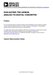
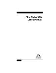
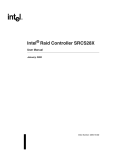
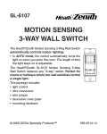
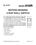
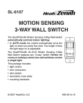
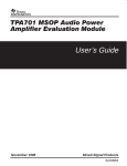
Dell™ OptiPlex™ 160L Service Manual
Removing the Computer Cover
Control Panel
I/O Panel
Power Supply
System Board
Replacing the Computer Cover
To remove or replace all other 160L components, see the 160L Systems User's Guide.
Notes, Notices, and Cautions
NOTE: A NOTE indicates important information that helps you make better use of your computer.
NOTICE: A NOTICE indicates either potential damage to hardware or loss of data and tells you how to avoid the problem.
CAUTION: A CAUTION indicates a potential for property damage, personal injury, or death.
Information in this document is subject to change without notice.
© 2003 Dell Computer Corporation. All rights reserved.
Reproduction in any manner whatsoever without the written permission of Dell Computer Corporation is strictly forbidden.
Trademarks used in this text: Dell, the DELL logo, and OptiPlex are trademarks of Dell Computer Corporation.
Other trademarks and trade names may be used in this document to refer to either the entities claiming the marks and names or their products. Dell Computer Corporation
disclaims any proprietary interest in trademarks and trade names other than its own.
Model: MTC2
June 2003 Rev. A00
Back to Contents Page
Control Panel
Dell™ OptiPlex™ 160L Service Manual
Removing the Control Panel
Replacing the Control Panel
CAUTION: Before you perform this procedure, see the safety instructions in your Setup and Quick Reference Guide.
NOTICE: To avoid electrostatic discharge, ground yourself by using a wrist grounding strap or by periodically touching an unpainted metal surface (such
as the back panel) on the computer.
NOTICE: Before you disconnect a device from the computer or remove a component from the system board, verify that the standby power light on the
system board has turned off. To locate the light, see "System Board Components."
1.
Shut down the computer through the Start menu.
2.
Ensure that your computer and attached devices are turned off. If your computer and attached devices did not automatically turn off when you shut
down your computer, turn them off now.
NOTICE: To disconnect a network cable, first unplug the cable from your computer and then unplug it from the network wall jack.
3.
Disconnect any telephone or telecommunication lines from the computer.
4.
Disconnect your computer and all attached devices from their electrical outlets, and press the power button to ground the system board.
CAUTION: To guard against electrical shock, always unplug your computer from the electrical outlet before removing the cover.
5.
Remove the computer cover.
NOTICE: Before touching anything inside your computer, ground yourself by touching an unpainted metal surface, such as the metal at the back of the
computer. While you work, periodically touch an unpainted metal surface to dissipate any static electricity that could harm internal components.
Removing the Control Panel
1.
Disconnect the control panel cable from the connector on the system board.
2.
Press the control panel lever to release the panel from the notch on the computer.
1 control panel
2 control panel lever
3 notch
4 system board connector
Replacing the Control Panel
1.
Insert the control panel tab into the notch on the chassis.
2.
Ensure that the control panel lever is secured by the tab on the chassis.
3.
Connect the control panel cable to the connector on the system board.
1 control panel lever
2 control panel tab
3 notch
4.
Replace the computer cover.
NOTICE: To connect a network cable, first plug the cable into the network wall jack and then plug it into the computer.
5.
Connect your computer and devices to electrical outlets, and turn them on.
Back to Contents Page
Back to Contents Page
Replacing the Computer Cover
Dell™ OptiPlex™ 160L Service Manual
CAUTION: Before you perform this procedure, see the safety instructions in your Setup and Quick Reference Guide.
1.
Ensure that all cables are connected, and fold cables out of the way.
2.
Ensure that no tools or extra parts are left inside the computer.
3.
Place the cover on the computer.
4.
Slide the cover toward the front of the computer until it fits completely into place.
NOTICE: To connect a network cable, first plug the cable into the network wall jack and then plug it into the computer.
3.
Connect your computer and any devices to electrical outlets, and turn them on. Back to Contents Page
Back to Contents Page
I/O Panel
Dell™ OptiPlex™ 160L Service Manual
Removing the I/O Panel
Replacing the I/O Panel
CAUTION: Before you perform this procedure, see the safety instructions in your Setup and Quick Reference Guide.
NOTICE: To avoid electrostatic discharge, ground yourself by using a wrist grounding strap or by periodically touching an unpainted metal surface (such
as the back panel) on the computer.
NOTICE: Before you disconnect a device from the computer or remove a component from the system board, verify that the standby power light on the
system board has turned off. To locate the light, see "System Board Components."
1.
Shut down the computer through the Start menu.
2.
Ensure that your computer and attached devices are turned off. If your computer and attached devices did not automatically turn off when you shut
down your computer, turn them off now.
NOTICE: To disconnect a network cable, first unplug the cable from your computer and then unplug it from the network wall jack.
3.
Disconnect any telephone or telecommunication lines from the computer.
4.
Disconnect your computer and all attached devices from their electrical outlets, and press the power button to ground the system board.
CAUTION: To guard against electrical shock, always unplug your computer from the electrical outlet before removing the cover.
5.
Remove the computer cover.
NOTICE: Before touching anything inside your computer, ground yourself by touching an unpainted metal surface, such as the metal at the back of the
computer. While you work, periodically touch an unpainted metal surface to dissipate any static electricity that could harm internal components.
Removing the I/O Panel
1.
Remove the hard drive(s).
2.
Cut the tie wrap cord that secures the I/O panel cables to the computer frame.
3.
Release and remove the front panel:
a.
Push the release lever to release the top tab.
b.
Reach inside the computer and push the bottom tab toward you to release it (the middle tab releases automatically).
c.
Rotate the front panel to separate it from the side hinges.
1 side hinges (3) 4 release lever
2 front panel
5 middle tab
3 top tab
6 bottom tab
4.
Remove the two screws that secure the I/O panel to the computer.
1 screws (2)
2 I/O panel
3 sound/USB cable
4 tie wrap cord
5.
Remove the I/O panel and disconnect the sound/USB cable from the I/O panel.
Replacing the I/O Panel
1.
Attach the sound/USB cable to the new I/O panel.
2.
Insert the I/O panel into the I/O cage and replace the screws that you removed in step 4.
1 screws (2)
2 I/O panel
3 I/O panel cage
3.
Reattach the front panel to the side hinges, and then rotate it until it snaps onto the front of the computer.
1 side hinges
2 front panel
4.
Reinstall the hard drive(s).
5.
Replace the computer cover.
NOTICE: To connect a network cable, first plug the cable into the network wall jack and then plug it into the computer.
6.
Connect your computer and devices to electrical outlets, and turn them on.
Back to Contents Page
Back to Contents Page
Power Supply
Dell™ OptiPlex™ 160L Service Manual
Removing the Power Supply
Replacing the Power Supply
DC Power Connectors
CAUTION: Before you perform this procedure, see the safety instructions in your Setup and Quick Reference Guide.
NOTICE: To avoid electrostatic discharge, ground yourself by using a wrist grounding strap or by periodically touching an unpainted metal surface (such
as the back panel) on the computer.
NOTICE: Before you disconnect a device from the computer or remove a component from the system board, verify that the standby power light on the
system board has turned off. To locate the light, see "System Board Components."
1.
Shut down the computer through the Start menu.
2.
Ensure that your computer and attached devices are turned off. If your computer and attached devices did not automatically turn off when you shut
down your computer, turn them off now.
NOTICE: To disconnect a network cable, first unplug the cable from your computer and then unplug it from the network wall jack.
3.
Disconnect any telephone or telecommunication lines from the computer.
4.
Disconnect your computer and all attached devices from their electrical outlets, and then press the power button to ground the system board.
CAUTION: To guard against electrical shock, always unplug your computer from the electrical outlet before opening the cover.
5.
Remove the computer cover.
NOTICE: Before touching anything inside your computer, ground yourself by touching an unpainted metal surface, such as the metal at the back of the
computer. While you work, periodically touch an unpainted metal surface to dissipate any static electricity that could harm internal components.
Removing the Power Supply
1.
Remove the fan assembly.
2.
Disconnect the AC power cable from the AC power connector on the back of the power supply.
3.
Unplug the DC power cables from the drives and system board.
4.
Remove the four screws that secure the power supply to the back of the computer.
1 screws (4)
2 power supply
5.
Remove the power supply from the computer.
Replacing the Power Supply
1.
Slide the power supply into place.
2.
Replace the four screws that secure the power supply to the back of the computer.
3.
Reinstall the fan assembly.
4.
Reconnect the DC power cables to the drives and system board.
5.
Replace the computer cover.
6.
Connect the AC power cable to the AC power connector on the back of the power supply.
NOTICE: To connect a network cable, first plug the cable into the network wall jack and then plug it into the computer.
7.
Connect your computer and devices to electrical outlets, and turn them on.
DC Power Connectors
Power Supply DC Connector Pin Assignments
Main Power Connector
Pin
Signal Name
Number
22-AWG
Wire
1
Orange
+3.3 VDC
2
+3.3 VDC
Orange
3
COM
Black
4
+5 VDC
Red
5
COM
Black
6
+5 VDC
Red
7
COM
Black
8
PWR_OK
Gray
9
+5 VSB
Purple
10
+12 VDC
Yellow
11
+3.3 VDC
[+3.3 V default
sense]
Orange
[Brown]
12
–12 VDC
Blue
13
COM
Black
14
PS ON#
Green
15
COM
Black
16
COM
Black
17
COM
Black
18
N/C
N/C
19
+5 VCD
Red
20
+5 VCD
Red
12-volt Power Connector
Pin Number
Signal Name
22-AWG Wire
1
COM
Black
2
COM
Black
3
+12 VDC
Yellow
4
+12 VDC
Yellow
Peripheral Power Connectors
Pin Number
Signal Name
22-AWG Wire
1
+12 VDC
Yellow
2
COM
Black
3
COM
Black
4
+5 VDC
Red
Floppy Drive Power Connector
Back to Contents Page
Pin Number
Signal Name
22-AWG Wire
1
+5 VDC
Red
2
COM
Black
3
COM
Black
4
+12 VDC
Yellow
Back to Contents Page
System Board
Dell™ OptiPlex™ 160L Service Manual
System Board Components
Jumper Settings
Replacing the System Board
System Board Components
1 power connector (J21)
10 front-panel audio connector (J29)
2 hard-drive connector (J23)
11 PCI card Slots (3) (PCI1, PCI2, PCI3)
3 CD drive connector (J20)
12 modem telephony connector (J25)
4 floppy-drive connector (J18)
13 CD audio connector (J8)
5 control panel connector (J28)
14 12V POWER connector (J10)
6 battery socket (BT1)
15 processor connector (U16)
7 clock jumper (CLEAR CMOS)
16 fan connector (J30)
8 front-panel connector (J27)
17 memory module connectors (DDR1, DDR2)
9 password jumper (CLEAR PASSWORD) 18 power indicator (LED1)
Jumper Settings
NOTICE: Ensure that your computer is turned off and unplugged before you change the jumper settings. Otherwise, damage to your computer or
unpredictable results can occur.
NOTICE: Before touching anything inside your computer, ground yourself by touching an unpainted metal surface, such as the metal at the back of the
computer. While you work, periodically touch an unpainted metal surface to dissipate any static electricity that could harm internal components.
To change a jumper setting, pull the plug off its pin(s) and carefully fit it down onto the pin(s) indicated.
Jumper
Setting
CLEAR
PASSWORD
Description
Password features are enabled.
(default)
Password features are disabled.
CLEAR CMOS jumpered Real-time clock reset.
unjumpered
Resetting CMOS Settings
CAUTION: Before you perform this procedure, see the safety instructions in your Setup and Quick Reference Guide.
NOTICE: To avoid electrostatic discharge, ground yourself by using a wrist grounding strap or by periodically touching an unpainted metal surface (such
as the back panel) on the computer.
NOTICE: Before you disconnect a device from the computer or remove a component from the system board, verify that the standby power light on the
system board has turned off. To locate the light, see "System Board Components."
1.
Shut down the computer through the Start menu.
2.
Ensure that your computer and attached devices are turned off. If your computer and attached devices did not automatically turn off when you shut
down your computer, turn them off now.
NOTICE: To disconnect a network cable, first unplug the cable from your computer and then unplug it from the network wall jack.
3.
Disconnect any telephone or telecommunication lines from the computer.
4.
Disconnect your computer and all attached devices from their electrical outlets, and then press the power button to ground the system board.
CAUTION: To guard against electrical shock, always unplug your computer from the electrical outlet before opening the cover.
5.
Remove the computer cover.
NOTICE: Before touching anything inside your computer, ground yourself by touching an unpainted metal surface, such as the metal at the back of the
computer. While you work, periodically touch an unpainted metal surface to dissipate any static electricity that could harm internal components.
6.
Reset the current CMOS settings:
7.
a.
Locate the Clear Password and Clear CMOS jumpers on the system board.
b.
Remove the password jumper from its pins.
c.
Place the password jumper on the Clear CMOS pins and wait approximately 5 seconds.
d.
Remove the jumper from the Clear CMOS pins and place the jumper back on the password pins.
Replace the computer cover.
NOTICE: To connect a network cable, first plug the cable into the network wall jack and then plug it into the computer.
8.
Connect your computer and devices to electrical outlets, and turn them on.
Replacing the System Board
CAUTION: Before you perform this procedure, see the safety instructions in your Setup and Quick Reference Guide.
NOTICE: To avoid electrostatic discharge, ground yourself by using a wrist grounding strap or by periodically touching an unpainted metal surface (such
as the back panel) on the computer.
NOTICE: Before you disconnect a device from the computer or remove a component from the system board, verify that the standby power light on the
system board has turned off. To locate the light, see "System Board Components."
1.
Shut down the computer through the Start menu.
2.
Ensure that your computer and attached devices are turned off. If your computer and attached devices did not automatically turn off when you shut
down your computer, turn them off now.
NOTICE: To disconnect a network cable, first unplug the cable from your computer and then unplug it from the network wall jack.
3.
Disconnect any telephone or telecommunication lines from the computer.
4.
Disconnect your computer and all attached devices from their electrical outlets, and then press the power button to ground the system board.
CAUTION: To guard against electrical shock, always unplug your computer from the electrical outlet before opening the cover.
5.
Remove the computer cover.
NOTICE: Before touching anything inside your computer, ground yourself by touching an unpainted metal surface, such as the metal at the back of the
computer. While you work, periodically touch an unpainted metal surface to dissipate any static electricity that could harm internal components.
Removing the System Board
1.
If a floppy drive is installed, remove the floppy drive.
2.
Remove any installed cards.
3.
Disconnect all cables from the system board.
4.
Disconnect the fan power cable from the connector on the system board.
5.
Remove the shroud/fan assembly.
CAUTION: The processor heat sink can get hot. To avoid burns, ensure that the heat sink has had sufficient time to cool before you touch it.
6.
Remove the processor heat sink.
7.
Remove the 12 screws that secure the system board to the computer frame.
Four of the 12 screws that secure the system board to the computer frame also secure the heat-sink base to the system board.
1 system board screws (8)
2 heat-sink base screws (4)
8.
Lift the system board out from the computer.
9.
Place the system board that you just removed next to the replacement system board.
Visually compare the replacement system board to the existing system board to ensure that you have the correct part.
Replacing the System Board
1.
Transfer components from the existing system board to the replacement system board:
a.
Remove the memory modules and install them on the replacement board.
CAUTION: The processor can get hot. To avoid burns, ensure that the processor has had sufficient time to cool before you touch it.
b.
2.
Remove the processor from the existing system board and transfer it to the replacement system board.
Configure the settings of the replacement system board.
Set the jumpers on the replacement system board so they are identical to the ones on the existing board.
3.
Place the system board inside the computer frame, place the heat-sink base on the system board, and then replace the screws that you removed in
step 7 of the preceding procedure.
4.
Reinstall the processor heat sink.
5.
Reinstall the shroud/fan assembly and then lower the heat-sink shroud.
6.
Reattach the cables to the system board.
7.
Reinstall any cards.
8.
Replace the floppy drive, if used.
9.
Replace the computer cover.
NOTICE: To connect a network cable, first plug the cable into the network wall jack and then plug it into the computer.
10.
Connect your computer and devices to electrical outlets, and turn them on.
Back to Contents Page
Back to Contents Page
Removing the Computer Cover
Dell™ OptiPlex™ 160L Service Manual
CAUTION: Before you perform this procedure, see the safety instructions in your Setup and Quick Reference Guide.
1.
Shut down the computer through the Start menu.
2.
Ensure that your computer and attached devices are turned off. If your computer and attached devices did not automatically turn off when you shut
down your computer, turn them off now.
NOTICE: To disconnect a network cable, first unplug the cable from your computer and then unplug it from the network wall jack.
3.
Disconnect any telephone or telecommunication lines from the computer.
4.
Disconnect your computer and all attached devices from their electrical outlets, and then press the power button to ground the system board.
CAUTION: To guard against electrical shock, always unplug your computer from the electrical outlet before removing the cover.
5.
Lay your computer on its side with the computer cover facing up.
6.
While keeping the cover latch in the open position, grip the indents and slide the computer cover toward the back of the computer.
7.
Place the computer cover on a level surface.
1 computer cover
2 cover latch
Back to Contents Page