1
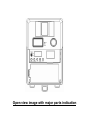
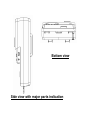
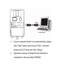
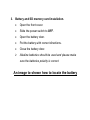
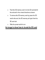
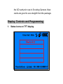
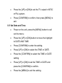
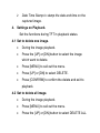
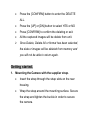
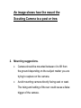
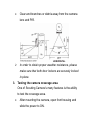
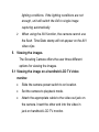
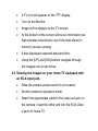
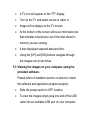
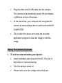
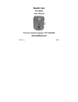
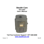
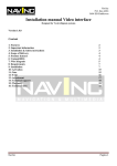
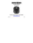
Scouting Camera
User’s Manual
Model: WF-037a
Open view image with major parts indication
Bottom view
Side view with major parts indication
Attention.
The software CD-ROM packaged with the camera is
designed for PC’s only. Playing this CD-ROM on a stereo or
CD player may cause damage to it.
This camera is a precision electronic device. Do not
attempt to service this camera yourself, as opening or
removing covers may expose you to dangerous voltage
points or other risks.
Please use the lens cloth to clear the lens and do not
touch the lens with fingers.
Getting to know your Scouting Camera
1. Package contents.
Please check if the following items are in the package
when purchasing this product.
•
CDROM (Contented with Ulead PE 8 and driver)
•
User Manual.
•
1.5M USB cable.
•
1.5M TV out cable for TV (RCA Jack).
•
Strap.
Installation.
1. Preparation.
•
CDROM – Contains Scouting Camera driver and
application program.
•
USB cable – Comes with product.
•
TV out cable – Comes with product.
•
Battery – 6 Alkaline batteries, size C
2. Software installation.
•
Unplug the USB cable from PC.
•
Insert the CDROM in CD driver of your PC.
•
The auto-run program will execute.
•
Follow the instructions shown on screen from your
PC to completely install the driver and application
program.
•
Restart windows.
•
Successful installation will create “Ulead Photo
Explorer” icon on you desktop.
•
Power off the unit.
•
Connect your camera to the PC by the USB cable,
the PC will recognize the new device and set UP the
configuration of the PC automatically.
•
A new disk will be found under My Computer.
¾
If your computer dosen’t run automatically, please
click “Start” button and choose “Run”, and then
browse the CD drive and click “Setup”.
¾
Operation manual of Ulead Photo Explorer is
contained on the provided CDROM.
3. Battery and SD memory card installation.
•
Open the front cover.
•
Slide the power switch to OFF.
•
Open the battery door.
•
Put the battery with correct directions.
•
Close the battery door.
¾
Alkaline batteries should be used and please make
sure the batteries polarity is correct.
An image to shown how to locate the battery
•
Push the SD memory card in to the SD card slot till
the end and in the correct direction as shown.
•
To remove the SD memory card by press the SD
card to the end, the SD memory will eject from the
SD card slot.
•
Slide the power switch to on.
An image to show how to locate the SD card
4. Memory Options.
You Scouting camera is comes 16MB built in flash
memory, the camera is also equipped with an expendable
media card slot capable accepting up to 512M SD memory
card (sold separately), With no memory card inserted into the
slot, the camera will use the built in 16MB memory, If a SD
memory card is inserted into the slot then the camera will
bypass the built in memory and utilize the compact flash
memory. The front counter display will show the number of
images on the built in memory unless the expansion card is
inserted at which point the counter will only show the number
of images o the expansion card.
¾
The camera should be in the OFF position when
adding or removing the memory cards.
¾
SD memory cards must be clean (not images from
other sources), if you are using the SD memory card
from other cameras, please make sure the format
the SD card prior use in Scouting Camera. New
cards are good to use straight from the package.
Display, Controls and Programming.
1. Status Icons on TFT display.
•
Time out: To set the time amount of time the camera
will sleep between PIR triggering.
•
Auto Flash: If the brightness is lower then EV 12.
the unit will turn on the flash lighting automatically.
•
Capture mode: It shown the capture mode that you
have selected.
o
1P: Single image capturing per PIR triggering.
o
2P: Two images continuous capturing per PIR
triggering.
o
3P: Three images continuous capturing per PIR
triggering.
o
Video: Taking 10 seconds video per PIR
triggering.
•
Resolution: It shown the resolution selection that
you have selected.
o 1600 x 1200 2.0M: Select this option to capture
a 2.0M pixels image.
o 1280 x 1024 1.3M: Select this option to capture
a 1.3M pixels image.
o 640 x 480
VGA: Select this option to capture a
300K pixels image.
o 320 x 240 Video resolution: This is the resolution
during Video capturing and resolution is 100K
pixels.
•
Batteries Status: It shows the battery status.
o Full: It shows the batteries are full.
o Half: It shows the batteries are half.
o Low: It shows the batteries are low and front
battery indicator will be on also.
¾
When the camera has detected low batteries,
(Batteries are lower then 4.0 +/-0.2Volts) the camera
unit will power off within 30 seconds automatically.
Please replace with new batteries; otherwise the
camera will not work properly.
•
Day and Time: It shows the date and time that you
have set.
2. Controls.
•
Change the display mode to Preview:
By pressing and hold the [CONFIRM] button 2
seconds to switch the TFT display mode to Preview,
the TFT display will show the image what you
pointed.
•
Change the display mode to Playback:
By pressing and hold the [CONFIRM] button 2
seconds to switch the TFT display mode to Playback
from Preview, the TFTdisplay will show the captured
images.
•
Wake up the unit during PIR detection.
By pressing the [UP] or [DOWN] button 2 seconds to
wake up the unit inter preview.
3. Settings on Preview.
Set the functions during TFT in preview status.
3.1 Set the Capturing mode:
•
Power on the unit, press the [MENU] button to call
out the menu.
•
Press [UP] or [DN] to move the highlight to
CAPTURE MODES.
•
Then press the [CONFIRM] button to into the capture
setting.
•
Press the [UP] or [DN] button to select the capturing
and press the [CONFIRM] to confirm.
•
Press [MENU] again to exit the capturing mode
settings.
¾
If no buttons are pressed within 30 seconds, the unit
will return 1minute count down mode then start PIR
capturing.
3.2 Set the Resolutions:
•
Power on the unit, press the [MENU] button to call
out the menu.
•
Press the [UP] or [DN] to move the highlight to
RESOLUTION
•
Then press the [CONFIRM] button to into the
resolution settings.
•
Press the [UP] or [DN] button to select the
resolutions and press [CONFIRM] to confirm.
•
Press [MENU] button again to exit the resolution
setting.
3.3 Set the Time out:
•
Power on the unit, press the [MENU] button to call
out the menu.
•
Press the [UP] or [DN] button to move the highlight
to TIME OUT.
•
Press [CONFIRM] to into the setting.
•
Press [UP] or [DN] button to set the time out time on
minutes.
•
Press [CONFIRM] again to confirm the setting.
•
Then press [MENU] again to exit the setting.
3.4 Set TV output system.
•
Power on the unit, press the [MENU] button to call
out the menu.
•
Press the [UP] or [DN] button to move the highlight
to TV OUT.
•
Press [CONFIRM] to enter the setting.
•
Press the [UP] or [DN] to set the TV output in NTSC
or PAL system.
•
Press [CONFIRM] to confirm, then press [MENU] to
exit.
3.5 Set Date and Time.
•
Power on the unit, press the [MENU] button to call
out the menu.
•
Press the [UP] or [DN] button to move the highlight
to DATE AND TIME.
•
Press [CONFIRM] to enter the setting.
•
Press [UP] or [DN] to select the TIME or DATE.
•
Press the [CONFIRM] to select the TIME or DATE
setting.
•
Press [UP] or [DN] to set the TIME or DATE and
press the [CONFIRM] to confirm.
•
Press the [MENU] to exit the setting.
¾
Date Time Stamp to stamp the date and time on the
captured image.
4. Settings on Playback.
Set the functions during TFT in playback status.
4.1 Set to delete one image.
•
During the image playback.
•
Press the [UP] or [DN] button to select the image
which want to delete.
•
Press [MENU] to call out the menu.
•
Press [UP] or [DN] to select DELETE.
•
Press [CONFIRM] to confirm the delete and exit to
playback.
4.2 Set to delete all image.
•
During the image playback.
•
Press [MENU] to call out the menu.
•
Press the [UP] or [DN] button to select DELETE ALL.
•
Press the [CONFIRM] button to enter the DELETE
ALL.
•
Press the [UP] or [DN] button to select YES or NO
•
Press [CONFIRM] to confirm the deleting or exit.
•
All the captured images will be delete from unit.
¾
Once Delete, Delete All or format has been selected,
the data or images will be deleted from memory and
you will not be able to return again.
Getting started.
1. Mounting the Camera with the supplier strap.
•
Insert the strap through the strap slots on the rear
housing.
•
Wrap the strap around the mounting surface. Secure
the strap and tighten the buckle in order to secure
the camera.
An image shows how the mount the
Scouting Camera to a post or tree.
2. Mounting suggestions.
•
Camera should be mounted between 4 to 6ft from
the ground depending on the subject matter you are
trying to capture on the camera.
•
Avoid mounting camera directly facing east or west.
The rising and setting of the sun could cause a false
trigger of the camera.
•
Clear and branches or debris away from the camera
lens and PIR.
¾
In order to obtain proper weather resistance, please
make sure that both door lockers are securely locked
in place.
3. Testing the camera coverage area.
One of Scouting Camera’s many features is the ability
to test the coverage area.
•
After mounting the camera, open front housing and
slide the power to ON.
•
After the font LCD screen has powered on. Press the
[TEST] button (this must be done with in 30 seconds
or the camera will enter count down mode)
•
Close the front housing.
•
Walk around in the front of the camera to see if you
have mounted camera in the proper position. A green
indicator light on the front will blink on when you
have intruded the coverage area.
•
Adjust the camera position as needed and repeat
testing until the desired coverage area is achieved.
•
When you have completed the testing the coverage
area there are 2 methods for exiting the test mode:
a. Open the front housing and press the [TEST]
button to exit test mode. The camera will then
enter count down mode for 1 minute and front
green indicator will start blinking giving you one
minute to leave the coverage area. Then the
camera will enter PIR detection mode.
b. After 5 minutes in test mode, the camera will
then enter count down mode for 1 minutes and
the front green indicator will start blinking giving
you one minute to leave the coverage area. The
camera will enter PIR detection mode.
4. Using the camera in PIR detection mode.
•
Mount the camera to tree or other sturdy object using
either two supplied tree screw or mounting strap
(Please refer to the mounting suggestions section in
this manual)
•
Open the front housing and move the switch to the
ON position. At this point you have 30 seconds to
make any program adjustments.
•
After 30 seconds the camera’s green test light will
begin blinking and enter count down mode. This is
your indication to leave the coverage area with one
minute.
•
After one minute the camera will take between 1~3
pictures or a 10 seconds AVI video based on your
program setting. The camera will then time out
between 1 ~ 60 minutes also based on your setting.
¾
The time between motion detection and the camera
taking the pictures may vary due to lighting
conditions, charging of the flash, program setting and
battery power level.
¾
The flash lighting will only activate in low light
conditions.
¾
When the camera is set to AVI capturing, the 10
seconds clips will only turn out well in good daytime
lighting conditions. If the lighting conditions are not
enough, unit will switch the AVI to single image
capturing automatically.
¾
When using the AVI function, the camera cannot use
the flash. Time/Date stamp will not appear on the AVI
video clips.
5. Viewing the images.
The Scouting Camera offers the user three different
options for viewing the images.
5.1 Viewing the image on a handheld LCD TV video
monitor.
•
Slide the camera power switch to on location.
•
Set the camera to playback mode.
•
Attach the appropriate cable to the video out jack on
the camera. Insert the other end into the video in
jack on handheld LCD TV monitor.
•
A TV icon will appear on the TFT display.
•
Turn on the Monitor.
•
Image will be display on the TV screen.
•
At the bottom of the screen will be an information bar
that indicates what picture out of the total stored in
memory you are viewing.
•
It also displayed captured data and time.
•
Using the [UP] and [DN] buttons navigate through
the images one at one times.
5.2 Viewing the images on your home TV equipped with
an RCA input jack.
•
Slide the camera power switch to on location.
•
Set the camera to playback mode.
•
Attach the appropriate cable to the video out jack on
the camera. Insert the other end into the RCA video
in jack on home TV.
•
A TV icon will appear on the TFT display.
•
Turn on the TV and select source to video in.
•
Image will be display on the TV screen.
•
At the bottom of the screen will be an information bar
that indicates what picture out of the total stored in
memory you are viewing.
•
It also displayed captured data and time.
•
Using the [UP] and [DN] buttons navigate through
the images one at one times.
5.3 Viewing the images on your computer using the
provided software.
Please refer to Installation section on above to install
the software and application program properly.
•
Slide the power switch to OFF location.
•
To view the images simply plug one end of the USB
cable into an available USB port on your computer.
•
Plug the other end of USB cable into the camera.
The camera will automatically power ON and display
a USB icon on the LCD screen.
•
At the same time, your computer will recognize the
camera as mass storage device and found under MY
COMPUTER.
•
Clip to open this device and using the provided
application program to view the image or edit the
image.
Using the external power.
1. To use the external battery pack power.
•
Insert the battery pack plug into the DC 12V jack of
the bottom of camera housing
•
Turn the camera power on.
¾
Please make sure the voltage and polarity are
correct before connection. Incorrect voltage or
polarity will damage the camera. If you are not sure,
please contact your retailer.
Maintenance
1. Storing conditions.
•
Operating Environment: 41 to 104 deg F (5 to 40 deg
C). 20-85% relative humidity, non-condensing.
2. Special care instructions!!
•
The camera is designed to be weather resistant.
Never attempt to t immerse he unit to water or any
other liquid. This will damage the unit and valid the
warranty.
•
Remove dust or stains with a soft cloth dampened
with water or neutral detergent. Keep the Scouting
Camera in a dry and cool dust-free environment or
container when it is NOT used.
•
Take the batteries out, when the Scouting Camera is
NOT to be used over a long period.
•
Avoid dropping the Scouting Camera on to hard
ground. Do not to disassemble the Scouting Camera.
•
Do not mix new and old batteries.
•
Do not open the camera for unauthorized services.
This could cause serious damage to the unit and will
valid the warranty.
Troubleshooting and Hints
1. Monitor resolution adjustment.
You need to set the display of your PC monitor
resolution to 16 bit colour or higher for Optimum image
display. Please refer to the display card manual or
following the below procedure to setting Hi Colour (16
bit) or above:
•
Click the Windows Start button.
•
Click settings and then Control Panel from the popUP MENUs.
•
Double click the Display icon.
•
Click the Setting tab.
•
Please select to High Colour (16 bit) or True Colour
(24 bit). Then choose High Colour or True Colour
from the list box.
•
Click O.K. If need to update the monitor driver,
please do it to change to the new setting.
•
Restart your computer.
2. SD memory card use.
You are recommended to FORMAT the SD memory
card before you save on image to it when..
•
You use a new SD Card
•
You have used the SD card in other digital devices
(the format of the SD card might have changed when
using other devices due to un-standard formats).
Camera spec and system compatibility.
1. System Requirements and Compatibility.
•
Windows 98/98se/2000/Me/XP.
•
P 450MHz or equivalent processor.
•
128MB SDRAM or above.
•
VGA Video Card with 32MB RAM for minimum,
Colour 16 bit or higher.
•
An available CDROM driver and an available USB
Port.
•
600 MB free hard disc space.
•
Optional: Windows compatible sound card,
Microphone and speaker.
¾
If you have any questions regarding your PC
specifications please call your PC manufacturer.
2. Camera Features and Specification.
•
Image sensor: 2.1M pixels RGB color.
•
Built in 1.5” Color TFT display with backlight.
•
Built in 16M flash memories for image storage.
•
Ext memory support: SD memory card up to 512M.
•
Resolution Options: VGA, 1.3M, 2.0M.
•
4 Capturing Options: Manual, Single, Continuous,
AVI.
•
Image performance for video stream: 10fps in 320 x
240 pixels, approx 10 seconds per section.
•
Auto white balance and auto expose.
•
Auto Flash light strobe control.
•
Real time clock for date and time stamping.
•
4 digits LCD counter.
•
Battery low indicator.
•
TV out support for NTSC and PAL system.
•
Focusing: 1.5m min to Infinity.
•
High precision 6 P glass lens with IR coating.
•
Effective viewing Angle: 52 deg.
•
PIR detection angle 48 deg.
•
Adjustable PIR detection range up to 9 meter.
•
Low power consumption:
Standby current: < 1mA.
Capture current <150mA
•
Interface type: USB 1.1.
•
Power: C size alkaline Batteries x 4.
•
Ext power: 12 volts battery pack.
•
Image format: Standard JEPG. And Motion JEPG
(AVI)
Safety.
This device complies with Part 15 of the FCC Rules.
Operation is subject to the following two conditions: (1) This
device may not cause harmful interference, and (2) This
device must accept any interference received, including
interference that may cause undesired operation.
Warning: Changes or modification to this unit not expressly
approved by the party responsible for compliance could void
the user’s authority to operate the equipment.
NOTE: This equipment has been tested and found to comply
with the limited for Class B digital device, pursuant to Part 15
of the FCC Rules. Their limits are designed to provide
reasonable protection against harmful interference in a
residential installation. This equipment generates, uses and
can radiate radio frequency energy and, if not installed and
used in accordance with the instructions, may cause harmful
interference to radio communications.
However, there is no guarantee that interference will not
occur in a particular installation. If the equipment does cause
harmful interference to radio or television reception, which
can be determined by turning the equipment off and on, the
user is encouraged to try to correct the interference by one or
more of the following measures:
Reorient or relocate the receiving antenna.
Increase the separation between the equipment and
receiver.
Connect the equipment into an outlet on a circuit
different from that to which the receiver is connected.
Consult the dealer or an experienced radio/TV technician
for help.
Rev 0.0