1
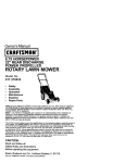
Owner's Manual
iCRRFTSMRW I
LAWN TRACTOR
14.5 HP, 38" Mower
Electric Start
5 Speed Transaxle
Model No.
917.258010
I_
differently from previously built engines. Before you start the
his product
has aunderstand
low emission
which
operates
engine,
read and
this engine
Owner's
Manual.
CAUTION:
Read and follow all Safety
Rules and Instructions before
For answers to your questions
about this product, Call:
operating this equipment.
Sears Craftsman Help Line
5 am - 5 pm, Mon - Sat
1-800-859-5917
Sears, Roebuck and Co., Hoffman Estates, II 60179 U.S.A.
Visit our Craftsman
website:www.sears.condcraftsman
Maintenance ....................................... 17
Service and Adjustments .................... 21
Storage ............................................... 27
Troubleshooting ................................. 28
Repair Pads ........................................ 32
Sears Service ...................... Back Cover
Warranty ............................................... 2
Safety Rules ......................................... 3
Product Specifications .......................... 6
Assembly/Pre-Operation ...................... 8
Operation ............................................ 11
Maintenance Schedule ...................... 17
LIMITED
WARRANTY
ON CRAFTSMAN
RIDING
EQUIPMENT
For two (2) years from the date of purchase, if this Craftsman Riding Equipment is
maintained, lubricated and tuned up according to the instructions in the owner's
manual, Sears will repair or replace free of charge any parts that are found to be
defective in material or workmanship according to the guidelines of coverage listed
below. Sears will also provide free labor for these applicable warranted pads for the
two fullyears. During the first 30 days of purchase, there will be no charges to service
the product at your home for issues covered by this warranty. (See exclusions below).
For your convenience, IN HOME warranty service will still be available after the first 30
days of purchase, but a trip charge will apply. This charge will be waived if the Craftsman product is dropped offat an authorizedSears location. For the nearest authorized
Sears location, please call 1-800-4-MY-HOME®.
This warranty applies only while this
product is within the United States.
This Warranty does not cover:
• Expendable items which become worn during normal use, including but not limited
to blades, spark plugs, air cleaners, belts, and oil filters.
• Standard Maintenance Servicing, oil changes, or tune-ups
thorns, stumps, or glass.
Repairs necessary because of operator abuse, including]but not limited to, damage
caused
by towingor
objects
capability from
of theoutside
nding equipment,
impacting
Tire replacement
repair beyond
caused the
by punctures
objects, such
as nails,
objects that bend the frame or crankshaft, or over-speedin._ the engine.
Repairs necessary because of operator negligence, including but not limited to,
electdcal and mechanical damage caused by improper storage, failure to use the
proper grade and amount of engine oil, failure to keep the deck clear of flammable
debds, or failure to maintain the equipment according to the instructionscontained in
the owner's manual.
• Engine (fuel system) cleaning or repairs caused by fuel determined to be contaminated or oxidized (stale). In general, fuel should be used within 30 days of its
purchase date.
• Normal detedoration and wear of the extedor finishes, or product label replacement.
• Riding equipment used for commercial or rental purposes.
LIMITED WARRANTY ON BA'I-rERY
For ninety (90) days from date of purchase, if any battery included with this riding
equipment proves defective in material or workmanship and our testing determines the
battery will not hold a charge, Sears will replace the battery at no charge. During the
first 30 days of purchase, there will be no charges to replace the battery at your HOME.
After the first 30 days, for your convenience, IN-HOME warranty service will still be
available but a tdp charge will apply. This charge will be waived if the Craftsman
product is dropped of at an authorized Sears location. For the nearest authorized
Sears location, please call 1-800-4-MY-HOME®.
This battery
warranty applies only while this product
is within the United States.
This warranty gives you specific legal dghts, and you may also have other rights, which
vary, from state to state.
Sears, Roebuck and Co.,Dept.817WA, Hoffman Estates, IL 60179
2
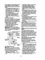
IMPORTANT: This cutting machine is capable of amputating hands and feet and
throwing objects. Failure to observe the following safety instructionscould result in
serious injury or death.
Look for this symbol to point out
important safety precautions. It means
CAUTIONI!I
BECOMEALERT!I!
SAFETY IS INVOLVED.
• Do not mow in reverse unless absolutely
necessary. Always look down and
behind before and while backing.
Be aware of the mower discharge
direction and do not point itat anyone.
Do not operate the mower without either
the entire grass catcher or the guard in
place.
Slow down before turning.
Never leave a running machine
unattended. Always turn off blades, set
parking brake, stop engine, and remove
keys before dismounting.
Turn off blades when not mowing.
Stop engine before removing grass
catcher or unclogging chute.
Mow only in daylight or good artificial
light.
Do not operate the machine while under
the influence of alcohol or drugs.
Watch for traffic when operating near or
crossing roadways.
Use extra care when loading or unloading the machine into a trailer or truck.
Data indicatesthat operators, age 60
years and above, are involved in a large
percentage of riding mower-related
injuries. These operators should
evaluate their ability to operate the riding
mower safely enough to protect themselves and others from serious injury.
Keep machine free of grass, leaves or
other debris build-up which can touch
hot exhaust / engine pads and bum. Do
not allow the mower deck to plow leaves
or other debds which can cause buildup to occur. Clean any oil or fuel
spillage before operating or storing the
machine. Allow machine to cool before
storage.
YOUR
_, CAUTION: In orderto prevent
accidental starting when setting up,
transporting, adjusting or making repairs,
always disconnect spark plug wire and
place wire where it cannot contact spark
plug.
CAUTION:
Do not coast down a hill
in neutral, you may lose control of the
tractor.
CAUTION: Tow only the attachments
that are recommended by and comply
with specifications of the manufacturer of
your tractor. Use common sense when
towing. Operate only at the lowest
possible speed when on a slope. Too
heavy of a load, while on a slope, is
dangerous. Tires can lose traction with
the ground and cause you to lose control
of your tractor.
_IbWARNING: Engine exhaust, some of
its constituents, and certain vehicle
components contain or emit chemicals
known to the State of California to cause
cancer and birth defects or other reproductive harm.
_WARNING:
Battery posts, terminals
and related accessodes contain lead
and lead compounds, chemicals known
to the State of California to cause cancer
and birth defects or other reproductive
harm. Wash hands after handling.
I. GENERAL
OPERATION
• Read, understand, and follow all
instructions in the manual and on the
machine before starting.
• Only allow responsible adults, who are
familiar with the instructions, to operate
the machine.
• Clear the area of objects such as rocks,
toys, wire, etc., which could be picked
up and thrown by the blade.
• Be sure the area is clear of other people
before mowing. Stop machine if anyone
enters the area.
• Never carry passengers.
II. SLOPE OPERATION
Slopes are a major factor related to loss-ofcontrol and tipover accidents, which can result in severe injury or death. All slopes
require extra caution. If you cannot back up
the slope or if you feel uneasy on it, do not
mow it.
3
DO:
• Mow up and down slopes, not across.
• Remove obstacles such as rocks, tree
limbs, etc.
• Watch for holes, ruts, or bumps. Uneven
terrain could overturn the machine. Tall
gress can hide obstacles.
• Use slow speed. Choose a low gear so
that you will not have to stop or shift
while on the slope.
• Follow the manufacturer's recommendations for wheel weights or counterweights to improve stability.
• Use extra care with grass catchers or
other attachments. These can change
the stability of the machine.
• Keep all movement on the slopes slow
and gradual. Do not make sudden
changes in speed or direction.
• Avoid starting or stopping on a slope. If
tires lose traction, disengage the blades
and proceed slowly straight down the
slope.
00 NOT:
• Do not turn on slopes unless necessary,
and then, turn slowly and gradually
downhill, if possible.
• Do not mow near drop-offs, ditches, or
embankments. The mower could
suddenly turn over if a wheel is over the
edge of a cliff or ditch, or if an edge
caves in.
• Do not mow on wet grass. Reduced
traction could cause sliding.
• Do not try to stabilize the machine by
putting your foot on the ground.
• Do not use grass catcher on steep
slopes.
III. CHILDREN
• Never carry children. They may fall off
and be seriously injured or interfere
with safe machine operation.
• Never allow children to operate the
machine.
• Use extra care when approaching blind
comers, shrubs, trees, or other objects
that may obscure vision.
IV. SERVICE
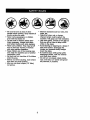
• Use extra care in handling gasoline
and other fuels. They are flammable
and vapors are explosive.
-Use only an approved container.
- Never remove gas cap or add fuel
with the engine running, Allow
engine to cool before refueling. Do
not smoke.
-Never refuel the machine indoors.
- Never store the machine or fuel
container inside where there is an
open flame, such as a water heater.
• Never run a machine inside a closed
area.
• Keep nuts and bolts, especially blade
attachment bolts, tight and keep
equipment in good condition.
• Never tamper with safety devices.
Check their proper operation regularly.
• Keep machine free of grass, leaves, or
other debris build-up. Clean oil or fuel
spillage. Allow machine to cool before
storing.
• Stop and inspect the equipment if you
strike an object. Repair, if necessary,
before restarting.
• Never make adjustments or repairs
with the engine running.
• Grass catcher components are subject
to wear, damage, and deterioreUon,
which could expose moving parts or
allow objects to be thrown. Frequently
check components and replace with
manufacturer's recommended parts,
when necessary.
• Mower blades are sharp and can cut.
Wrap the blade(s) or wear gloves, and
use extra caution when servicing them.
• Check brake operation frequently.
Adjust and service as required.
Tragic accidents can occur if the operator
is not alert to the presence of children.
Children are often attracted to the
machine and the mowing activity. Never
assume that children will remain where
you last saw them.
• Keep children out of the mowing area
and under the watchful care of another
responsible adult.
• Be alert and turn machine off if children
enter the area.
• Before and when backing, look behind
and down for small children.
4
• Be sure the area is clear of other
people before mowing. Stop machine if
anyone enters the area.
• Never carry passengers or children
even with the blades off.
• Do not mow in reverse unless absolutely necessary. Always look down
and behind before and while backing.
• Never carry children. They may fall off
and be seriously injured or interfere
with safe machine operation.
• Keep children out of the mowing area
and under the watchful care of another
responsible adult.
• Be alert and turn machine off if children
enter the area.
• Before and when backing, look behind
and down for small children.
• Mow up and down slopes (15 ° Max),
not across.
• Remove obstacles such as recks, tree
limbs, etc.
• Watch for holes, ruts, or bumps.
Uneven terrain could overturn the
machine. Tall grass can hide obstacles.
• Use slow speed. Choose a low gear so
that you will not have to stop or shift
while on the slope.
• Avoid starting or stopping on a slope. If
tires lose traction, disengage the
blades and proceed slowly straight
down the slope.
• If machine stops while going uphill,
disengage blades, shift into reverse
and back down slowly.
• Do not turn on slopes unless necessary, and then, turn slowly and gradually downhill, if possible.
5
PRODUCTSPECIFICA_ONS
A Repair Agreement Is available on this
product, Contact your nearest Sears
store for details.
Gasoline
1.25 Gallons
Capacity
and Type:
Unleaded
Regular
Oil Type:
'API-SF-SJ):
SAE 30 (above 32°F)
SAE 5W-30 (below 32°FI
Oil Capacity:
3.0 Pints
Spark Plug:
(Gap: .030")
Champion
Ground Speed
Forward:
(MPH):
CUSTOMER
1st
1.1
2nd
2.2
3rd
3.4
4th
4.3
5th
5.5
1.7
Tire Pressure:
Front:
Rear:
14 PSI
12 PSI
Charging
System:
3 Amps Battery
5 Amps Headlights
Battery:
Amp/Hr:
28
Min. CCA:
230
Case Size: U1R
RESPONSIBILITIES
• Read and observe the safety rules.
• Follow a regular schedule in maintaining, caring for and using your tractor.
• Follow the instructions under "Maintenance" and =Storage" sections of this
_owner's manual.
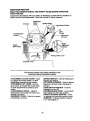
WARNING: This tractor is equipped
with an intemal combustion engine and
should not be used on or near any
unimproved forest-covered, brushcovered or grass-covered land unless the
engine's exhaust system is equipped with
a spark arrester meeting applicable local
or state laws (if any). If a spark arrestar is
used, it should be maintained in effective
working order by the operator.
In the state of California the above is
required by law (Section 4442 of the
California Public Resources Code).
Other states may have similar laws.
Federal laws apply on federal lands. A
spark arrester for the muffler is available
through your nearest Sears service
center (See REPAIR PARTS section of
this manual).
RC12YC
Reverse:
Blade Bolt Torque:
REPAIR AGREEMENT
27-35 Ft. Lbs.
CONGRATULATIONS on your purchase
of a new tractor. It has been designed,
engineered and manufactured to give
you the best possible dependability and
performance.
Should you experience any problem you
cannot easily remedy, please contact a
Sears or other qualified service center.
We have competent, well-trained technicians and the proper tools to service or
repair this tractor.
Please read and retain this manual. The
instructionswill enable you to assemble
and maintain your tractor properly.
Always observe the "SAFETY RULES".
6
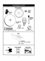
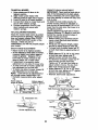
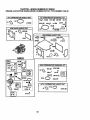
Steering Wheel
Steering
Extension
Shaft
Seat
(1) Washer
17/32 x 1-3/16 x 12 Gauge
(1) Knob
Keys
Video Cassette
(2) Keys
7
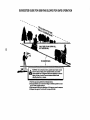
Slope Sheet
Yournewtractorhas been assembled at the factory with the exception of those parts
left unassembled for shipping purposes. To ensure safe and proper operation of your
tractor all parts and hardware you assemble must be tightened securely. Use the
correct tools as necessary to insure proper tightness. Review the video cassette before
you begin.
TOOLS REQUIRED
ASSEMBLY
FOR
A socket wrench set will make assembly
easier. Standard wrench sizes you need
are listed below.
(1) 3/4" wrench
(1) Pliers
(2) 7/16" wrench
(1) Utility knife
(1) Tire pressure gauge
When right or left hand is mentioned in
this manual, it means, from your point of
view, when you are in the operating
position (seated behind the steering
wheel).
TO REMOVETRACTOR FROM
CARTON
UNPACK
CARTON
1. Remove all accessible
loose parts
and parts boxes from carton.
2. Cut, from top to bottom, along lines
on all four corners of carton, and lay
panels flat.
3. Check for any additional loose parts
or cartons and remove.
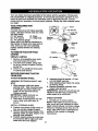
BEFORE REMOVING TRACTOR
FROM SKID
A'FrACH
STEERING
WHEEL
6. Assemble large flat washer, 1/2 hex
nut and tighten securely.
7. Snap steering wheel insert into center
of steering wheel.
8. Remove protective materials from
tractor hood and grill.
IMPORTANT: Check for and remove any
staples in skid that may puncture tires
where tractor is to roll off skid.
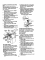
ASSEMBLE EXTENSION SHAFT AND
BOOT
1. Slide extension shaft onto lower
steering shaft. Align mounting holes
in extension and lower shafts and
install 114 hex bolt and Iocknut.
Tighten securely.
IMPORTANT: Tighten bolt and nut
securely to 10-12 ft. Ibs torque.
2. Place tabs of steering boot over tab
slots in dash and push down to
secure.
INSTALL STEERING
3.
4.
5.
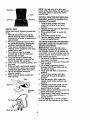
CHECK
1. Lift seat pan to raised position.
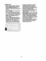
NOTE: If this battery is put into service
after month and year indicated on label
(label located between terminals) charge
battery for minimum of one hour at 6-10
amps. (See "BATI'ERY" in Maintenance
section of this manual for charging
instructions).
WHEEL
Position front wheels of the tractor so
they are pointing straight forward.
Remove steering wheel adapter from
steering wheel and slide adapter onto
steering shaft extension.
Position steedng wheel so cross bars
are horizontal (left to right) and slide
inside boot and onto adapter.
BATTERY
8
NOTE: You may now roll or drive your
tractor off the skid. Follow the appropriate
instruction below to remove the tractor
from the skid.
TO ROLLTRACTOR
OFF SKID (See
Operation section for location and
function of controls)
1, Press lift lever plunger and raise
attachment lift lever to its highest
position.
2, Release parking brake by depressing
clutch/brake pedal.
3, Place gearshift lever in neutral (N)
position.
4. Roll tractor forward off skid.
5, Remove banding holding deflector
shield up against tractor,
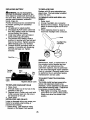
INSTALL SEAT
Adjust seat before tightening adjustment
knob.
1. Remove adjustment knob and fiat
washer securing seat to cardboard
packing and set aside for assembly of
seat to tractor.
2. Pivot seat upward and remove from
the cardboard packing. Remove the
cardboard packing and discard.
3. Place seat on seat pan so head of
shoulder bolt is positioned over large
slotted hole in pan.
4. Push down on seat to engage
shoulder bolt in slot and pull seat
towards rear of tractor.
5. Pivot seat and pan forward and
assemble adjustment knob and flat
washer loosely. Do not tighten.
6. Lower seat into operating position and
sit in seat.
7. Slide seat until a comfortable position
is reached which allows you to press
clutch/brake pedal all the way down.
8. Get off seat without moving its
adjusted position.
9. Raise seat and tighten adjustment
knob securely.
TO DRIVE TRACTOR OFF SKID (See
Operation section for location and
function of controls)
A(_WARNING: Before starting, read,
understand and follow all instructions in
the Operation section of this manual. Be
sure tractor is in a well-ventilated area. Be
sure the area in front of tractor is clear of
other people and objects.
1. Be sure all the above assembly steps
have been completed.
2. Check engine oil level and fill fuel tank
with gasoline.
3, Sit on seat in operating position,
depress clutch/brake pedal and set
the parking brake.
4. Place gear shift lever in neutral (N)
position.
5. Press lift lever plunger and raise
attachment lift lever to its highest
position.
6. Start the engine. After engine has
started, move throttle control to idle
position.
7. Depress clutch/brake pedal into full
"BRAKE" position and hold. Move
gearshift lever to 1st gear.
8. Slowly release clutch/brake pedal and
slowly drive tractor off skid.
9. Apply brake to stop tractor, set parking
brake and place gearshift lever in
neutral position.
10.Turn ignition key to "STOP" position.
Continue with the instructionsthat follow.
Seat
Bolt
Flat Wi%
_
9
CHECK
TIRE
/CHECKLIST
PRESSURE
The tires on your tractor were overinflated
at the factory for shipping purposes,
Correct tire pressure is important for best
cutting performance.
• Reduce tire pressure to PSI shown in
=PRODUCT SPECIFICATIONS"
section
of this manual.
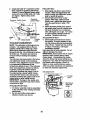
CHECKDECKLEVELNESS
For best cutting results, mower housing
should be properly leveled. See "TO
LEVEL MOWER HOUSING" in the
Service and Adjustments section of this
manual.
CHECK FOR PROPER POSITION OF
ALLBELTS
See the figures that are shown for
replacing motion and mower blade drive
belts in the Service and Adjustments
section of this manual. Verify that the
belts are routed correctly.
CHECK BRAKE SYSTEM
After you leam how to operate your
tractor, check to see that the brake is
properly adjusted. See "TO ADJUST
BRAKE" in the Service and Adjustments
section of this manual.
Before you operate your new tractor, we
wish to assure that you receive the best
performance and satisfaction from this
Quality Product.
Please review the following checklist:
/All assembly instructions have been
completed.
/ No remaining loose parts in carton.
/ Battery is properly prepared and
charged. (Minimum 1 hour at 6 amps).
,/Seat is adjusted comfortably and
tightened securely.
/ All tires are properly inflated. (For
shipping purposes, the tires were
ovednflated at the factory).
/ Be sure mower deck is properly leveled
side-to-side/front-to-rear for best cutting
results. (Tires must be properly inflated
for leveling).
/ Check mower and drive belts. Be sure
they are routed properly around pulleys
and inside all belt keepers.
/ Check wiring. See that all connections
are still secure and wires are propedy
clamped.
While learning how to use your tractor,
pay extra attention to the following
important items:
/ Engine oil is at proper level.
/ Fuel tank is filled with fresh, clean,
regular unleaded gasoline.
,/Become familiar with all controls - their
location and function. Operate them
before you start the engine.
4 Be sure brake system is in safe
operating condition.
10
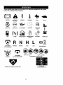
These symbols may appear on your tractor or in literature supplied with the product.
Learn and understand their meaning.
BATTERY
CAUTION OR
WARNING
REVERSE
FORWARD
FAST
SLOW
ENG,N=ON
ENG,NEOFF
O,LPRE_ORE
L,GHTSON
OVI_T_..
FUEL
CHOKE
MOWER HEIGHT
N
ATTACHMENT
CLUTCH ENGAGED
IGNITION
REVERSE
NEUTRAL
ATTACHMENT
CLUTCH DISENGAGED
PARKING BRAKE
LOCKED
H
L
HIGH
LOW
UNLOCKED
MOWER LIFT
PARKING BRAKE
KEEP AREA CLEAR
SLOPE HAZARDS
(SEE SAFETY RULES SECTION)
FREE WHEEL
DANGER. KEEP HANDS AND FEET AWAY
(Automatic Models only)
11
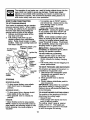
KNOW YOUR TRACTOR
READ THIS OWNER'S MANUAL AND SAFETY RULES BEFORE OPERATING
YOUR TRACTOR
Compare the illustrations with your tractor to familiadze yourself with the locations of
vadous controls and adjustments. Save this manual for future reference.
Attachment
Ammeter
Clutch
Ignition Switch
Lever
Plunger
Attachment
Lift Lever
Throffie/Choke
Control
Height
_ Adjustment
Indicator
Clutch/
Brake Pedal
Brake Lever
\
Our tractors conform to the safety standards of the
Amedcan National Standards Institute.
ATrACHMENT
CLUTCH LEVER - Used
to engage the mower blades, or other
attachments mounted to your tractor.
ATTACHMENT
LIFT LEVER - Used to
raise, lower, and adjust the mower deck
or other attachments mounted to your
tractor.
CLUTCH/BRAKE
PEDAL - Used for
declutching and braking the tractor and
starting the engine.
GEARSHIFT
LEVER - Selects the speed
and direction of tractor.
IGNITION SWITCH - Used for starting and
stopping the engine.
LIFT LEVER PLUNGER - Used to release
attachment lift lever when changing its
position.
LIGHT SWITCH POSITION - Turns the
headlights on and off.
PARKING BRAKE LEVER - Locks clutch/
brake pedal into the brake position.
THROTTLE/CHOKE
CONTROL - Used
for starting and controlling engine speed.
AMMETER
- Indicates battery charging
(+) or discharging (-).
12
The operation of any tractor can result in foreign objects thrown into the
eyes, which can result in severe eye damage. Always wear safety
glasses or eye shields while operating your tractor or performing any
adjustments or repairs. We recommend standard safety glasses or a
wide vision safety mask worn over spectacles.
HOW TO USE YOUR TRACTOR
TO SET PARKING BRAKE
Your tractor is equipped with an operator
presence sensing switch. When engine
is running, any attempt by the operator to
leave the seat without first setting the
parking brake will shut off the engine.
1. Depress clutch/brake pedal all the
way down and hold.
2. Pull parking brake lever up and
release pressure from clutch/brake
pedal. Pedal should remain in brake
position. Make sure parking brake will
hold tractor secure.
Throttle/Choke
Control
• Turn ignition key to "STOP" position
and remove key. Always remove key
when leaving tractor to prevent
unauthorized use.
• Never use choke to stop engine.
IMPORTANT: Leaving the ignition switch
in any position other than "STOP" will
cause the battery to discharge and go
dead.
NOTE: Under certain conditions when
tractor is standing idle with the engine
running, hot engine exhaust gases may
cause "browning" of grass. To eliminate
this possibility,always stop engine when
stopping tractor on grass areas.
Attachment Clutch Lever
=Engaged" Position
Ignition Key
Brake
Pedal
Parking
"Engaged"
Position
TO MOVE
=Disengaged"_'_
Position
STOPPING
MOWER
BLADES -
• To stop mower blades, move attachment clutch lever to disengaged
position.
GROUND
FORWARD
AND BACKWARD
The direction and speed of movement is
controlled by the gearshift lever.
1. Start tractor with clutch/brake pedal
depressed and gearshift lever in
neutral (N) position.
2. Move gearshift lever to desired
position.
3. Slowly release clutch/brake pedal to
start movement.
IMPORTANT:
Bring tractor to a complete
stop before shifting or changing gears.
Failure to do so will shorten the useful life
of your transaxle.
Gearshift
Lever
"Brake"
Position
_I=CA.UT!ON: A.Iwaysstop.tractor .
completed/, as oesciioea above, eerore
leaving the operator's position.
TO USE THRO'rrLE CONTROL
Always operate engine at full throttle.
• Operating engine at less than full
throttle reduces the battery charging
rate.
• Full throttle offers the best bagging and
mower performance.
DRIVE -
• To stop ground drive, depress clutch/
brake pedal all the way down.
• Move gearshift lever to neutral (N)
position.
TO ADJUST
MOWER
CU'I-I'ING
HEIGHT
The position of the attachment lift lever
determines the cutting height.
• Grasp lift lever.
• Press plunger with thumb and move
lever to desired position.
The cutting height range is approximately 1-1/2 to 4". The heights are
measured from the ground to the blade
tip with the engine not running.
ENGINE • Move throttle control to slow position.
NOTE: Failure to move throttle control to
slow position and allowing engine to idle
before stopping may cause engine to
"backfire".
13
• If slowing is necessary, move throttle
control lever to slower position.
• If stopping is absolutely necessary,
push clutch/brake pedal quickly to
brake position and engage parking
brake.
• Move gearshift leverto lstgear. Be
sure you have allowed room for tractor
to roll slightly as you restart movement.
• To restart movement, slowly release
parking brake and clutch/brake pedal.
• Make all turns slowly.
TO TRANSPORT
These heights are approximate and may
vary depending upon soil conditions,
height of grass and types of grass being
mowed.
• The average lawn should be cut to
approximately 2-1/2 inches during the
cool season and to over 3 inches
during hot months. For healthier and
better looking lawns, mow often and
after moderate growth.
• For best cutting performance, grass
over 6 inches in height should be
mowed twice. Make the first cut
relatively high; the second to desired
height.
TO OPERATE
• Raise attachment lift to highest position
with attachment lift control.
• When pushing or towing your tractor,
be sure gearshift lever is in neutral (N)
position.
• Do not push or tow tractor at more than
five (5) MPH.
NOTE: To protect hood from damage
when transporting your tractor on a truck
or a trailer, be sure hood is closed and
secured to tractor. Use an appropriate
means of tying hood to tractor (rope, cord,
etc.).
TOWING CARTS AND OTHER ATTACHMENTS
Tow only the attachments that are
recommended by and comply with
specifications of the manufacturer of your
tractor. Use common sense when towing.
Too heavy of a load, while on a slope, is
dangerous. Tires can lose traction with
the ground and cause you to lose control
of your tractor.
MOWER
Your tractor is equipped with an operator
presence sensing switch. Any attempt by
the operator to leave the seat with the
engine running and the attachment clutch
engaged will shut off the engine.
1. Select desired height of cut.
2. Start mower blades by engaging
attachment clutch control.
To stop mower blades ,_engage
attachment clutch control.
CAUTION:
Do not operate the mower
without either the entire grass catcher, on
mowers so equipped, or the deflector
shield in place.
Attachment Clutch Lever
Position
-Attachemnt
Uft Lever
High Position
Position
BEFORE
CHECK
THE
ENGINE
OIL LEVEL
The engine in your tractor has been
shipped, from the factory, already filled
with summer weight oil.
1. Check engine oil with tractor on level
ground.
2. Remove oil fill cap/dipstick and wipe
clean, reinsert the dipstick and screw
cap tight, wait for a few seconds,
remove and read oil level. If necessary, add oil until =FULL" mark on
dipstick is reached. Do not overfill.
• For cold weather operation you should
change oil for easier starting (See =OIL
VISCOSITY CHART" in the Maintenance section of this manual).
• To change engine oil, see the Maintenance section in this manual.
Shield
TO OPERATE
STARTING
ENGINE
ON HILLS
•(_CAUTION:
Do not drive up or down
hills with slopes greater than 15 ° and do
not drive across any slope. Use the slope
guide at the back of this manual.
• Choose the slowest speed before
starting up or down hills.
• Avoid stopping or changing speed on
hills.
14
ADD GASOLINE
• Fill fuel tank to bottom of tank filler
neck. Do not overfill. Use fresh, clean,
regular unleaded gasoline with a
minimum of 87 octane. (Use of leaded
gasoline will increase carbon and lead
oxide deposits and reduce valve life).
Do not mix oil with gasoline. Pumhase
fuel in quantities that can be used
within 30 days to assure fuel freshness.
5. Insert key into Ignition and tum key
clockwise to start position and release
key as soon as engine starts. Do not
run starer continuously for more than
fifteen seconds par minute. If the
engine does not start after several
attempts, move throttle control to fast
position, wait a few minutes and try
again. If engine still does not staR,
move the throttle control back to the
choke position and retry.
_1=CAUTION:
Wipe off any spilled oil or
fuel Do not store, spill or use gasoline
near an open flame.
WARM WEATHER STARTING (50 ° F and
above)
6. When engine stars, move the throttle
control to the fast position.
• The attachments and ground drive can
now be used. If the engine does not
accept the load, restart the engine and
allow it to warm up for one minute
using the choke as described above.
IMPORTANT:
When operating in
temperatures below 32°F(0°C), use fresh,
clean winter grade gasoline to help
insure good cold weather staring.
_1_ CAUTION:
Alcohol blended fuels
(called gasohol or using ethanol or
methanol) can attract moisture which
leads to separation and formation of
acids during storage. Acidic gas can
damage the fuel system of an engine
while in storage. To avoid engine
problems, the fuel system should be
emptied before storage of 30 days or
longer. Drain the gas tank, start the
engine and let it run until the fuel lines
and carburetor are empty. Use fresh fuel
next season. See Storage Instructions for
additional information. Never use engine
or carburetor cleaner products in the fuel
tank or permanent damage may occur.
COLD WEATHER STARTING ( 50 ° F and
below)
6. When engine starts, allow engine to
run with the throttle control in the
choke position until the engine runs
roughly, then move throttle control to
fast position. This may require an
engine warm-up period from several
seconds to several minutes, depending on the temperature.
• The attachments can also be used
during the engine warm-up period.
NOTE: If at a high altitude (above 3000
feet) or in cold temperatures (below 32 F)
the carburetor fuel mixture may need to
be adjusted for best engine performance.
(See 'q'O ADJUST CARBURETOR" in the
Service and Adjustments section of this
manual).
TO START ENGINE
When staring the engine for the first time
or if the engine has run out of fuel, it will
take extra cranking time to move fuel from
the tank to the engine.
1. Sit on seat in operating position,
depress clutch/brake pedal and set
parking brake.
2. Place gear shift lever in neutral (N)
position.
3. Move attachment clutch to disengaged position.
4. Move throttle control to choke position.
NOTE: Before starting, read the warm
and cold starting procedures below.
15
MOWING TIPS
• If grass is extremely tall, it should be
mowed twice to reduce load and
possible fire hazard from dried clippings. Make first cut relatively high; the
second to the desired height.
• Do not mow grass when it is wet. Wet
grass will plug mower and leave
undesirable clumps. Allow grass to dry
before mowing.
• Always operate engine at full throttle
when mowing to assure better mowing
performance and proper discharge of
material. Regulate ground speed by
selecting a low enough gear to give the
mower cutting performance as well as
the quality of cut desired.
• When operating attachments, select a
ground speed that will suit the terrain
and give best performance of the
attachment being used.
• Mower should be properly leveled for
best mowing performance. Sea =TO
LEVEL MOWER HOUSING" in the
Service and Adjustments section of this
manual.
• The left hand side of mower should be
used for trimming.
• Drive so that clippings are discharged
onto the area that has already been
cut. Have the cut area to the right of the
tractor. This will result in a more even
distribution of clippings and more
uniform cutting.
• When mowing large areas, start by
turning to the right so that clippings will
discharge away from shrubs, fences,
driveways, etc. After one or two
rounds, mow in the opposite direction
making left hand turns until finished.
f
l
16
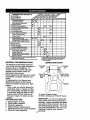
AS YOU COMPLETE
REGULAR
SERVICE
DATES
Check Tim
BrakeOperation
Check
P_um
Check Operator P_
_
aml
T Ch_k_
=_
sy==_
R
Loo_F=_,_
T
Lub_Uo.Ch=rt
0
R
Check BattmyLevel
Clean BaniMyand Temdnals
I_
V'_
V'
V _
ce_,kTra_ax_CooRr_
Check V-Belts
I_
Change Engine Oil (with oil finer)
V'l,=
E Change
F.ng_ne
OU(*_outoardter)
I/,_
G
N
C_nA_Fat_
Clean
Air Screen
_V':
NI
inspectMuffler/_park
Arrester
Vf.=
Replace Spark Plug
Cooang
Rr_
If
_
Replace Nr Riter Paper Cartridge
Replace Fuel R]tel"
1 - Che_le more olten when operating unde_i heavy load or
In hlg_ ='nb_e_ temperature=.
2 - Sewice more often when opera,rig in d_ty or dusty conditions.
GENERAL RECOMMENDATIONS
The warranty on this tractor does not
cover items that have been subjected to
operator abuse or negligence. To
receive full value from the warranty,
operator must maintain tractor as
instructed in this manual.
Some adjustments will need to be made
periodically to properly maintain your
tractor.
All adjustments in the Service and
Adjustments section of this manual
should be checked at least once each
season.
• Once a year you should replace the
spark plug, clean or replace air filter,
and check blades and belts for wear.
A new spark plug and clean air filter
assure proper air-fuel mixture and
help your engine run better and last
longer.
BEFORE EACH USE
1. Check engine oil level.
2. Check brake operation.
3. Check tire pressure.
4. Check operator presence and
interlock systems for proper operation.
5. Check for loose fasteners.
I,/
i
E Rop_eO_F_. (. eq_pp_)
Ckmn_
If
3 - Replace blades rnomoften when mowing in sandy soil.
4 - NOlrequired ffequipped with malnte_h_e
battery.
S - T_len flont axte pivot bolt to 35 fl.40_. maximurn.
Do not o_ghten.
LUBRICATION
Spindle
Zerk
_Fmnt Wheel
Bearing
Zerk
CHART
Zerk
Beadng Zerk
(_Engine
d) General Purpose Grease
_) Refer to Maintenance "ENGINE" Section
IMPORTANT:
Do not oil or grease the
pivot points which have special nylon
bearings. Viscous lubricants will attract
dust and dirt that will shorten the life of
the self-lubricating bearings. If you feel
they must be lubricated, use only a dry,
powdered graphite type lubricant
17 sparingly'
TRACTOR
Always observe safety rules when
performing any maintenance.
BRAKE OPERATION
If tractor requires more than six (6) feet
stopping distance at high speed in
highest gear, then brake must be adjusted. (See "TO ADJUST BRAKE" in the
Service and Adjustments section of this
manual).
TIRES
• Maintain proper air pressure in all tires
(See "PRODUCT SPECIFICATIONS"
section of this manual).
• Keep tires free of gasoline, oil, or insect
control chemicals which can harm
rubber.
• Avoid stumps, stones, deep ruts, sharp
objects and other hazards that may
cause tire damage.
NOTE: To seal tire punctures and prevent
flat tires due to slow leaks, tire sealant
may be purchased from your local parts
dealer. Tire sealant also prevents tire dry
rot and corrosion.
OPERATOR PRESENCE SYSTEM
Be sure operator presence and interlock
systems are working properly. If your
tractor does not function as described,
repair the problem immediately.
• The engine should not start unless the
clutch/brake pedal is fully depressed
and attachement clutch control is in the
disengaged position.
• When the engine is running, any
attempt by the operator to leave the
seat without first setting the parking
brake should shut off the engine.
• When the engine is running and the
attachment clutch is engaged, any
attempt by the operator to leave the
seat should shut off the engine.
• The attachment clutch should never
operate unless the operator is in the
seat.
BLADE CARE
For best results mower blades must be
kept sharp. Replace bent or damaged
blades.
BLADE REMOVAL
I.
IMPORTANT: To ensure proper assembly,
center hole in blade must align with star
on mandrel assembly.
4. Reassemble hex bolt, lock washer
and flat washer in exact order as
shown.
5. Tighten bolt securely (27-35 Ft. Lbs.
torque).
IMPORTANT: Blade bolt is grade 8 heat
treated.
Up
Blade
Washer,
Assembly
Star
Hole
Lock
/
_----Hex Bolt (Grade)
*A Grads 8 heat treated bolt can be identified
by six lines on the bolt head.
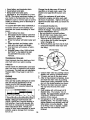
TO SHARPEN BLADE
NOTE: We do not recommend sharpening blade - but if you do, be sure the
blade is balanced.
Care should be taken to keep the blade
balanced. An unbalanced blade will
cause excessive vibration and eventual
damage to mower and engine.
• The blade can be sharpened with a file
or on a grinding wheel. Do not attempt
to sharpen while on the mower.
• To check blade balance, you will need
a 5/8" diameter steel bolt, pin, or a cone
balancer. (When using a cone balancar, follow the instructions supplied
with balancar.)
NOTE- Do not use a nail for balancing
blade. The lobes of the center hole may
appear to be centered, but are not.
• Slide blade on to an unthreaded
portion of the steel bolt or pin and hold
the bolt or pin parallel with the ground.
If blade is balanced, it should remain in
a horizontal position. If either end of
the blade moves downward, sharpen
the heavy end until the blade is
balanced.
+
^
maae
Raise mower to highest position to
Centel" Hole -_]
allow access to blades.
BATTERY
2. Remove hex bolt, lock washer and flat
Your tractor has a battery charging system
washer securing blade.
which is sufficient for normal usa. How3. Install new or rasharpened blade with
trailing edge up towards deck as
ever, periodic charging of the battery with
shown.
18an automotive charger will extend its life.
• Keepbatteryand terminals clean.
Change the oil after every 25 hours of
operation or at least once a year if the
tractor is not used for 25 hours in one
year.
Check the crankcase oil level before
starting the engine and after each eight
(8) hours of operation. _ghten oil fill cap/
dipstick securely each time you check the
oil level.
• Keep battery bolts tight.
• Keep small vent holes open.
• Recharge at 6-10 amperes for I hour.
NOTE: The original equipment battery on
your tractor is maintenance free. Do not
attempt to open or remove caps or covers.
Adding or checking level of electrolyte is
not necessary.
TO CLEAN BA'I-I'ERY AND TERMINALS
TO CHANGE ENGINE OIL
Determine temperature range expected
before oil change. All oil must meet API
service classification SF-SJ.
• Be sure tractor is on level surface.
• Oil will drain more freely when warm.
• Catch oil in a suitable container.
1. Remove oil fill cap/dipstick. Be careful
not to allow dirt to enter the engine
when changing oil.
2. Remove yellow cap from end of drain
valve and install the drain tube onto
the fitting.
Corrosion and dirt on the battery and
terminals can cause the battery to "leak"
power.
1. Open battery box door.
2. Disconnect BLACK battery cable first
then RED battery cable and remove
battery from tractor.
3. Rinse the battery with plain water and
dry.
4. Clean terminals and battery cable
ends with wire brush until bright.
5, Coat terminals with grease or petroleum jelly.
6. Reinstall battery (See "REPLACING
BA'I-rERY" in the SERVICE AND
ADJUSTMENTS
section of this
manual).
TRANSAXLE
Oil Drain Valve
Closed
and
_
Locked
COOLING
Keep transaxle free from build-up of dirt
and chaff which can restrict cooling.
Pos_on
V-BELTS
Check V-belts for deterioration and wear
after 100 hours of operation and replace
if necessary. The belts are not adjustable.
Replace belts if they begin to slip from
wear.
LUBRICATION
Only use high quality detergent oil rated
with API service classification SF-SJ
Select the oil's SAE viscosity grade
according to your expected operating
temperature.
.30
.I 0
0
"I'EMPERA'i'IJRE RANGE ANTIOPATED
t0
20
.
_
7.
Refill engine with oil through oil fill
dipstick tube. Pour slowly. Do not
overfill. For approximate capacity see
=PRODUCT SPECIFICATIONS"
section of this manual.
8.
Use gauge on oil fill cap/dipstick for
checking level. For accurate reading,
tighten dipstick cap securely onto the
tube before removing dipstick. Keep
oil at =FULL" line on dipstick. Tighten
cap onto the tube securely when
finished.
30
BEFORE NEXT OIL CHANGE
NOTE: Although multi-viscosity oils
(5W30, 10W30 etc.) improve starting in
cold weather, these multi-viscosity oils
will result in increased oil consumption
when used above 32°F. Check your
engine oil level more frequently to avoid
possible engine damage from running
low on oil.
_r_ L .'"
_ _ _
['_----_j
3. Unlock drain valve by pushing inward
slightly and turning counterclockwise.
4. To open, pull out on the drain valve.
5. After oil has drained completely, close
and lock the drain valve by pushing
inward and tuming clockwise until the
pin is in the locked position as shown,
6. Remove the drain tube and replace
the cap onto the end of the drain
valve.
ENGINE
C
,___
19
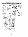
AIR FILTER
Your engine will not run properly using a
dirty air filter. Clean the foam pro-cleaner
after every 25 hours of operation or every
season. Service paper cartddge every
100 hours of operation or every season,
whichever occurs first.
Service air cleaner more often under
dusty conditions.
1. Remove knob(s) and cover.
TO
2.
3,
4.
5.
SERVICE PRE-CLEANER
Slide foam pre-cleaner off cartridge.
Wash it in liquid detergent and water.
Squeeze it dry in a clean cloth.
Saturate it in engine oil. Wrap it in
clean, absorbent cloth and squeeze to
remove excess oil.
NOTE: If very dirty or damaged, replace
pre-cleaner.
6. Reinstall pre-cleaner over cartridge.
7. Reinstall cover and secure with
knob(s).
TO SERVICE CARTRIDGE
1. Remove cartddge nut.
2. Carefully remove cartridge to prevent
debris from entering carburetor.
Clean base carefully to prevent debris
from entering carburetor.
3. Clean cartridge by tapping gently on
flat surface.
NOTE: If very dirty or damaged, replace
cartridge.
4. Reinstall cartridge, nut, precleaner,
cover and secure with knob(s).
IMPORTANT: Petroleum solvents, such
as kerosene, are not to be used to clean
the cartridge. They may cause deterioration of the cartridge. Do not oil cartddge.
Do not use pressurized air to clean or dry
cartridge.
Cover
Nut
Foam
Pre-Cleane_
Cartridge
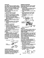
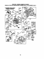
ENGINE COOLING RNS
Remove any dust, dirt or oil from engine
cooling fins to prevent engine damage
from overheating.
1. Remove screws from blower housing
and lift housing and dipstick tube
assembly off engine.
2. Cover oil fill opening to prevent entry
of dirt.
3. Use compressed air or stiff bdstle
brush to thoroughly clean engine
cooling fins.
To reassemble, reverse above
procedure.
.
Screws
Screws
Assembly
Plug
Engine Cooling
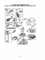
MUFFLER
Inspect and replace corroded muffler and
spark arroster (if equipped) as it could
create a fire hazard and/or damage.
SPARK PLUG(S)
Replace spark plug(s) at the beginning of
each mowing season or after every 100
hours of operation, whichever occurs first.
Spark plug type and gap setting are
shown in "PRODUCT SPECIFICATIONS"
section of this manual.
IN-LINE
FUEL FILTER
The fuel filter should be replaced once
each season. If fuel filter becomes
clogged, obstructing fuel flow to carburetor, replacement is required.
1. With engine cool, remove filter and
plug fuel line sections.
2. Place new fuel filter in position in fuel
line with arrow pointing towards
carburetor.
3. Be sure there are no fuel line leaks
and clamps are properly positioned.
4. Immediately wipe up any spilled
CLEAN AIR SCREEN
Air screen must be kept free of dirt and
chaff to prevent engine damage from
overheating. Clean with a wire brush or
compressed air to remove dirt and
stubborn dried gum fibers.
Blower Housing
gasoline.
Clamp
Fuel Filter -,__
2O
_J
CLEANING
We do not recommend using a garden
hose to clean your tractor unless the
electdcal system, muffler, air filter and
carburetor are covered to keep water out.
Water in engine can result in a shortened
engine life.
all foreign
i of
Clean
engine,matter.
battery, seat, finish, etc.
Keep finished surfaces and wheels free
of all gasoline, oil, etc.
• Protect painted surfaces with automotive type wax.
_b
WARNING: TO AVOID SERIOUS INJURY, BEFORE PERFORMING ANY
SERVICE OR ADJUSTMENTS:
1.
2.
3.
4.
5.
6.
Depress clutch/brake pedal fully and set parking brake.
Place gearshift lever in neutral (N) position.
Place attachment clutch in "DISENGAGED" position.
Turn ignitionkey to =STOP" and remove key.
Make sure the blades and all moving parts have completely stopped.
Disconnect spark plug wire from spark plug and place wire where it cannot
come in contact with plug.
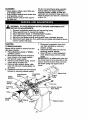
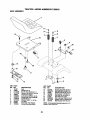
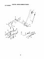
TRACTOR
7. Disconnect suspension arms from
rear deck brackets by removing
retainer springs.
8. Disconnect front links from deck by
removing retainer springs.
9. Raise lift lever to raise suspension
arms. Slide mower out from under
tractor.
IMPORTANT: If an attachment other than
the mower deck is to be mounted on the
tractor, remove the front links and hook
the clutch spring Into square hole in
frame.
TO REMOVE MOWER
Mower will be easier to remove from the
right side of tractor.
1. Place attachment clutch in "DISENGAGED" position.
2. Move attachment lift lever forward to
lower mower to its lowest position.
3. Roll belt off engine pulley.
4. Remove small retainer spring, and lift
clutch spring off pulley bolt.
5. Remove large retainer spring, slide
collar off and push housing guide out
of bracket.
6. Disconnect anti-sway bar from chassis
bracket by removing retainer spring.
Clutch
Small Retainer
Spdn_
Suspension
Arms
Retainer
Sprin!
Hole
Engine
Front Link
Anti-Sway
Bar
prings
(Both Sides)
Housing
Guide
Retainer
Shield
Spring
21
TO INSTALL MOWER
1. Raise attachment lift lever to its
highest position.
2. Slide mower under tractor with
deflector shield to right side of tractor.
3. Lower lift lever to its lowest position.
4. Connect front links to mower deck and
secure with retainer springs.
5. Connect suspension arms to rear
deck brackets and secure with
retainer springs.
FRONT-TO-BACK
ADJUSTMENT
IMPORTANT:.
Deck must be level side-to
side. If the following front-to-back adjustment is necessary, be sure to adjust both
front links equally so mower will stay level
side-to-side.
To obtain the best cutting results, the
mower housing should be adjusted so
that the front is approximately 1/8 =to 1/2"
lower than the roar when the mower is in
its highest position.
Check adjustment on right side of tractor.
Measure distance UD" directly in front and
behind the mandrel at bottom edge of
mower housing as shown.
• Before making any necessary adjustments, check that both front links are
equal in length.
• If links are not equal in length, adjust
one link to same length as other link.
• To lower front of mower loosen nut "E"
on both front links an equal number of
turns.
• When distance =D" is 1/8" to 1/2" lower
at front than roar, tighten nuts =P
against trunnion on both front links.
• To raise front of mower, loosen nut =F"
from trunnion on both front links.
Tighten nut =E" on both front links an
equal number of turns, The two front
links must remain equal in length.
• When distance =D" is 1/8" to 1/2" lower
at front than rear, tighten nut up against
trunnion on both front links.
• Recheck side-to-side adjustment.
TO LEVEL MOWER HOUSING
Adjust the mower while tractor is parked
on level ground or driveway. Make sure
tiros are properly inflated (See =PRODUCT SPECIFICATIONS" section of this
manual). If tires are over or
underinflated, you will not properly adjust
your mower,
SIDE-TO-SIDE
ADJUSTMENT
• Raise mower to its highest position.
• At the midpoint of both sides of mower,
measure height from bottom edge of
mower to ground.
Distance =A" on
both sides of mower should be the
same or within 1/4" of each other.
• If adjustment is necessary, make
adjustment on one side of mower only.
• To raise one side of mower, tighten lift
link adjustment nut on that side.
• To lower one side of mower, loosen lift
link adjustment nut on that side.
NOTE:
Each full turn of adjustment nut
will change mower height about 1/8".
• Recheck measurements after adjusting.
Bottom edge of
mower to ground
Mandrel
Bottom edge of
mower to ground
Both Front Links Should be Equal in Length
_=
Suspension Arm
Nut
Front
22
TO REPLACE
BELT
MOWER
BLADE
DRIVE
.
The mower blade drive belt may be
replaced without tools. Park the tractor on
level surface. Engage parking brake.
,
BELT REMOVAL 1. Place attachment clutch in "DISENGAGED" position.
2. Move attachment lift lever forward to
lower mower to its lowest position.
3. Roll belt off engine pulley.
4. Disconnect R.H. suspension arm from
rear deck bracket by removing
retainer spring.
5. Work belt off both mandrel pulleys and
idler pulleys.
6. Pull belt away from mower.
Nut "A"
BELT INSTALLATION
1. Work new belt around both mandrel
pulleys and idler pulleys.
2. Install new belt into engine pulley
grove.
3. Reconnect R.H. suspension arm and
secure with retainer spdng.
4. Make sure belt is in all pulley grooves
and inside all belt guides.
Mandrel
If distance is other than 1-1/2", loosen
jam nut and turn nut "A" until distance
becomes 1-1/2'.
Retighten jam nut
against nut "A".
Road test tractor for proper stopping
distance as stated above. Readjust if
necessary. If stopping distance is still
greater than six (6) feet in highest
gear, further maintenance is necessary. Contact a Sears or other
qualified service center.
With Parking Brake "Engaged"
Jam Nut
Arm
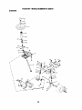
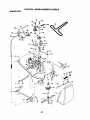
TO REPLACE
MOTION
Park the tractor on level surface. Engage
parking brake. For assistance, there is a
belt installation guide decal on bottom
side of left footrest.
Idler
Pulleys
BELT REMOVAL
-R,H.
Suspension
Retainer
Spring
Mandrel
Pulley
TO ADJUST
DRIVE BELT
BRAKE
Your tractor is equipped with an adjustable brake system which is mounted on
the right side of the transaxle.
If tractor requires more than six (6) feet
stopping distance at high speed in
highest gear on a level dry concrete or
paved surface, then brake must be
adjusted.
1. Depress clutch/brake pedal and
engage parking brake.
2. Measure distance between brake
operating arm and nut "A" on brake
rod.
-
1. Remove mower (See "TO REMOVE
MOWER" in this section of manual).
NOTE: Observe entire motion drive belt
and position of all belt guides and
keepers.
2. Remove belt from stationary idler and
clutching idler.
3. Remove belt downward from around
engine pulley.
4. Pull belt slack toward rear of tractor.
Remove belt upwards from transaxle
pulley by deflecting belt keepers.
5. Remove belt from center span keeper
and pull belt away from tractor.
BELT INSTALLATION
-
1. Carefully work new belt down between transaxle belt keepers and onto
the input pulley.
2. Slide belt into the center span keeper.
3. Pull belt toward front of tractor and roll
around the top groove of engine
pulley.
.
Install belt through stationary idler and
clutching idler.
23
5. Makesure belt is in all pulley grooves
and insideall belt guidesand keep-
TO START ENGINE WITH A WEAK
_'_'A ERY
RNING: Lead-acid batteries
ers.
6.
Install mower (See "TO INSTALL
MOWER" in this section of manual).
generate explosive gases. Keep sparks,
flame and smoking materials away from
batteries. Always wear eye protection
when around batteries.
If your battery is too weak to start the
engine, it should be recharged. (See
"BA'I-I'ERY" in the MAINTENANCE
section of this manual).
If =jumper cables" are used for emergency
starting, follow this procedure:
IMPORTANT:
Your tractor is equipped
with a 12 volt system. The other vehicle
must also be a 12 volt system. Do not use
your tractor battery to start other vehicles.
Engine
Pulley_
Clutching_
Idler
Stationary /
J
Center Span _
Keeper
Transaxle--.
Pulley I
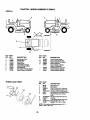
TO ATTACH JUMPER
TO ADJUST
MENT
STEERING
WHEEL
ALIGN-
-
1. Connect one end of the RED cable to
the POSITIVE (+) terminal of each
battery(A-B), taking care not to short
against tractor chassis.
2. Connect one end of the BLACK cable
to the NEGATIVE (-) terminal (C) of
fully charged battery.
3. Connect the other end of the BLACK
cable (D) to good chassis ground,
away from fuel tank and battery.
If steedng wheel crossbars are not
horizontal (left to right) when wheels are
positioned straight forward, remove
steedng wheel and reassemble with
crossbars horizontal. Tighten securely.
FRONT WHEEL TOE-IN/CAMBER
The front wheel toe-in and camber are
not adjustable on your tractor. If damage
has occurred to affect the front wheel toein or camber, contact a Sears or other
qualified service center.
TO REMOVE WHEEL FOR REPAIRS
TO REMOVE
ORDER -
CABLES,
REVERSE
1. BLACK cable first from chassis and
then from the fully charged battery.
2. RED cable last from both batteries.
1. Block up axle securely.
2. Remove axle cover, retaining ring and
washers to allow wheel removal (rear
wheels have a square key - Do not
lose).
3. Repair tire and reassemble.
NOTE: On rear wheels only: align
grooves in rear wheel hub and axle.
Insert square key.
4. Replace washers and snap retaining
ring securely in axle groove.
5. Replace axle cover.
NOTE: To seal tire punctures and prevent
flat tires due to slow leaks, purchase and
use tire sealant from Sears. Tire sealant
also prevents tire dry rot and corrosion.
Weak or Dead
Battery
Washers
Retaining
Ring
Axle
Cover
Square Key
(Rear Wheel Only) /
CABLES
24
Fully Charged
Battery
REPLACING BATTERY
A
_LWARNING,:,
Do not short battery
terminals Dy a,owing a wrencn or any
other object to contact both terminals at
the same time. Before connecting battery,
remove metal bracelets, wristwatch
bands, rings, etc.
Positive terminal must be connected first
to prevent sparking from accidental
grounding.
1. Lift seat pan to raised position.
2. Disconnect BLACK battery cable first
then RED battery cable and carefutly
remove battery from tractor.
3. Install new battery with terminals in
same position as old battery.
4. First connect RED battery cable to
positive (+) terminal with hex bolt and
keps nut as shown. Tighten securely.
Slide terminal cover over terminal
5. Connect BLACK grounding cable to
negative (-) terminal with remaining
hex bolt and keps nut. Tighten
securely.
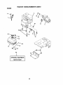
TO REPLACE FUSE
Replace with 20 amp automotive-type
plug-in fuse. The fuse holder is located
behind the dash.
TO REMOVE
SEMBLY
1. Raise hood.
2. Unsnap headlight wire connector.
3. Stand in front of tractor. Grasp hood at
sides, tilt toward engine and lift off of
tractor.
4. When replacing hood, be sure to
reconnect headlight wire connector.
Headlight Wire
Connector
®
Seat Pan
Ten'nina]
Positive
(Red)
Cable
TO REPLACE
ENGINE
Maintenance, repair, or reptacement of
the emission control devices and systems, which are being done at the
customers expense, may be performed
by any non-road engine repair establishment or individual. Warranty repairs must
be performed by an authorized engine
manufacturer's service outlet.
Keps
TO ADJUST
CABLE
Negative (Black) Cable
HEADLIGHT
HOOD AND GRILL AS-
BULB
1. Raise hood.
2. Pull bulb holder out of the hole in the
backside of the grill.
3. Replace bulb in holder and push bulb
holder securely back into the hole in
the backside of the grill.
4. Close hood.
INTERLOCKS
AND RELAYS
THROTTLE
CONTROL
The throffie control has been preset at the
factory and adjustment should not be
necessary. Check adjustment as dascnbed
below before loosening cable. If adjustment
is necessary, proceed as follows:
1. W'_h engine not running, move throStle
control lever from slow to choke position.
Slowly move lever from choke to fast
position.
Loose or damaged wiring may cause your
tractor to run poorly, stop running, or
prevent it from starting.
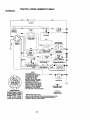
• Check wiring. See electrical wiring
diagram in the Repair Parts section.
25
FINAL SE'n'ING1. Start engineand allowto warm for five
minutes. Make final adjustmentswith
engine runningand shiff/matJoncontrol
lever in neutral (N) pos'_on.
2. Move throttlecontrolleverto slew
position.With finger, rotateand hold
throttle lever againstidle speed screw.
Tum idlespeed screwto attain 1750
RPM.
3. While stillholdingthrottle leveragainst
idlespeed screw,tum idle mixture valve
full travel clockwisethen counterclockwise untilengine runs rough. Tum valve
to a pointmidwaybetween thosetwo
positions. Release throttlelever.
2. Chsckthat holes=A" ingovemorconbol
lever and hole in governorplate line-up.
If holes=A"are not aligned, loosendamp
screw and move throttlecable until holes
are aligned. Tightenclamp screw
securely.
GovernorControl Lever
Governor
ControlPlate
\
Holes
"A"
Clamp Screw
ACCELERATION TEST4. Move throttle control lever from slow to
Throttle
Cable
TO ADJUST CARBURETOR
NOTE: The carburetoron this engineis low
emissidn. It is equippedwithan idlefuel
adjustingneedle witha limitercap, which
allowssome adjustment withinthe limits
allowedby the cap. Do not attemptto rernove
the limitercap. The limltercap cannotbe
removed withoutbreakingthe adjusting
needle.
The carburetor has been preset at the factory
and adjustment ,shouldnot be necessa.,y.
However, minoradjustmentmay be required
to compensatefor differencesin fuel,
temperature,altitudeor load. If the carburetor
does need adjustment,proceed as follows:
In general, tumingidle mixturevalve in
(clockwise)decreases the supplyof fuel to
the engine gMng a leanerfueVairmixture.
Tumingthe idle mixturevalve out (counter_)
increasesthe supplyof fuel to the
engine gMng a richerfueVairmixture.
IMPORTANT: Damage to the needle valve
and the seat in carburetormay resultif screw
istumed in too tight.
PREUMINARY SETTING 1. Air cleaner assembly must be assembled
to the carburetorwhen makingcarburetor
adjustments.
2. Be sure the throttle control cable is
adjustedproperly(see above).
26
fast position. If engine hesitates or dies,
tum idle mixture valve out (counterclockwise) 1/8 tum. Repeat test and continue
to adjust, if necessary, until engine
accelerates smoothly.
High speed stop is factory adjusted. Do not
adjust or damage may result.
IMPORTANT: Never temper with the engine
gevemor, which is facto,'y set for proper
engine speed. Overspeeding the engine
above the factory high speed seUJngcan be
dangerous, ff you think the engine-gevemed
high speed needs adjusting, contact a
Sears or other qualified service center,
wh'K_ has proper equipment and experience
to make any necessary adjustments.
Idle Speed Screw
Lever
Idle Mixture
Valve with
Limiter
Immediately prepare your tractor for
storage at the end of the season or if the
tractor will not be used for 30 days or
more.
_CAUTION:
Never store the tractor with
gasoline in the tank inside a building
where fumes may reach an open flame or
spark. Allow the engine to cool before
storing in any enclosure.
TRACTOR
Remove mower from tractor for winter
storage. When mower is to be stored for
a period of time, clean it thoroughly,
remove all dirt, grease, leaves, etc. Store
in a clean, dry area.
1. Clean entire tractor (See "CLEANING"
in the Maintenance section of this
manual).
2. Inspect and replace belts, if necessary
(See belt replacement instructions in
the Service and Adjustments section
of this manual).
3. Lubricate as shown in the Maintenance section of this manual.
4. Be sure that all nuts, bolts and screws
are securely fastened. Inspect moving
parts for damage, breakage and wear.
Replace if necessary.
5. Touch up all rusted or chipped paint
surfaces; sand lightly before painting.
Also, alcohol blended fuels (called
gasohol or using ethanol or methanol)
can attract moisture which leads to
separation and formation of acids during
storage. Acidic gas can damage the fuel
system of an engine while in storage.
1. Drain the fuel tank.
2. Start the engine and let it run untilthe
fuel lines and carburetor are empty.
• Never usa engine or carburetor cleaner
products in the fuel tank or permanent
damage may occur.
• Usa fresh fuel next season.
NOTE: Fuel stabilizer is an acceptable
alternative in minimizing the formation of
fuel gum deposits during storage. Add
stabilizer to gasoline in fuel tank or
storage container. Always follow the mix
ratio found on stabilizer container. Run
engine at least 10 minutes after adding
stabilizer to allow the stabilizer to reach
the carburetor. Do not drain the gas tank
and carburetor if using fuel stabilizer.
ENGINE OIL
Drain oil (with engine warm) and replace
with clean engine oil. (See "ENGINE" in
the Maintenance section of this manual).
CYLINDER(S)
1. Remove spark plug(s).
2. Pour one ounce of oil through spark
plug hole(s) into cylinder(s).
3. Tum ignition key to start positionfor a
few seconds to distribute oil.
4. Replace with new spark plug(s).
OTHER
BA'I'rERY
• Fully charge the battery for storage.
• After a period of time in storage, battery
may require recharging.
• To help prevent corrosion and power
leakage during long periods of storage,
battery cables should be disconnected
and battery cleaned thoroughly (see
"TO CLEAN BATTERY AND TERMINALS" in the Maintenance section of
this manual).
• After cleaning, leave cables disconnected and place cables where they
cannot come in contact with battery
terminals.
• If battery is removed from tractor for
storage, do not store battery directly on
concrete or damp surfaces.
• Do not store gasoline
to another.
• Replace your gasoline can if your can
starts to rust, Rust and/or dirt in your
gasoline will cause problems.
* If possible, store your tractor indoors
and cover it to give protection from dust
and dirt.
• Cover your tractor with a suitable
protective cover that does not retain
moisture. Do not use plastic. Plastic
cannot breathe which allows condensation to form and will cause your
tractor to rust.
IMPORTANT:
Never cover tractor while
engine and exhaust areas are still warm.
ENGINE
FUEL SYSTEM
IMPORTANT:
It iS important to prevent
gum deposits from forming in essential
fuel system parts such as carburetor, fuel
hose, or tank during storage.
from one season
27
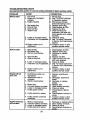
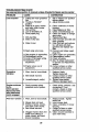
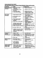
TROUBLESHOOTING
CHART:
See appropriate section in manual unless directed
PROBLEM
CAUSE
CORRECTION
Wlll not start
1. Out of fuel.
2. Engine not =CHOKED"
properly.
3. Engine flooded.
Hard to start
1. Dirty air filter.
2. Bad spark plug.
3. Weak or dead battery.
1. Fill fuel tank.
2. See "TO START ENGINE"
in Operation section.
3. Wait several minutes
before attempting to start.
4. Bad spark plug.
4. Replace spark plug.
5. Dirty air filter.
5. Clean/replace air filter.
6. Dirty fuel filter.
6. Replace fuel filter.
7 Water in fuel.
7. Drain fuel tank and
carburetor, refill tank with
fresh gasoline and replace
fuel filter.
8. Loose or damaged wiring.
8. Check all widng.
9. Carburetor out of adjustment. 9. See "To Adjust Carburetor"
in Service and Adjustments
section.
10. Engine valves out of
10.Contact a Sears or other
adjustment.
qualified service center.
4.
5.
Dirty fuel filter.
Stale or dirty fuel.
6.
7.
Loose or damaged wiring.
Carburetor out of adjustment.
8. Engine valves out of
adjustment.
Englnewlll not
turn over
1. Clutch/brake pedal not
depressed.
2. Attachment clutch is
engaged.
3. Weak or dead battery.
1. Clean/replace air filter.
2. Replace spark plug.
3. Recharge or replace
battery.
4. Replace fuel filter.
5. Drain fuel tank and refill
with fresh gasoline.
6. Check all wiring.
7. See "To Adjust Carburetor"
in Service and Adjustments
section.
8. Contact a Sears or other
qualified service center.
9. Faulty operator presence
switch(es).
1. Depress clutch/brake
pedal.
2. Disengage attachment
clutch.
3. Recharge or replace
battery.
4. Replace fuse.
5. Clean battery terminals.
6. Check all wiring.
7. Check/replace ignition
switch.
8. Check/replace solenoid or
starter.
9. Contact a Sears or other
qualified service center.
1.
2.
3.
4.
1.
2.
3.
4.
4.
5.
6.
7.
Blown fuse.
Corroded battery terminals.
Loose or damaged wiring.
Faulty ignition switch.
8. Faulty solenoid or starter.
Engine clicks but
wlll not start
to Sears service center
Weak or dead battery.
Corroded battery terminals.
Loose or damaged wiring.
Faulty solenoid or starter.
28
Recharge or replace battery.
Clean battery terminals.
Check all wiring.
Check/replace
solenoid or
starter.
TROUBLESHOOTINGCHART:
See appropriate section In manual unless directed to Sears service center
PROBLEM
CAUSE
Loss of power
.
2.
3.
4.
5.
6.
CORRECTION
Cutting too much grass/too
fast.
Throttle in =CHOKE"
position.
Build-up of grass, leaves
and trash under mower.
Dirty air filter.
Low oil level/dirty oil.
Faulty spark plug.
7. Dirty fuel filter.
8. Stale or dirty fuel.
9. Water in fuel.
10.Spark
plug wire loose.
11. Dirty engine air screen/fins.
12. Dirty/clogged muffler.
13.Loose or damaged wiring.
14. Carburetor out of
adjustment.
15. Engine valves out of
adjustment.
Excessive
vibration
1. Worn, bent or loose blade.
2.
Bent blade mandrel.
3. Loose/damaged part(s).
Engine continues
to run
•hen operator
leaves seat wlth
_vlth attachment
_lutch engaged
Poorcut-uneven
1. Faulty operator-safety
presence control system.
.
Worn, bent or loose blade.
2. Mower deck not level.
3. Buildup of grass, leaves,
and trash under mower.
4. Bent blade mandrel.
5.
Clogged mower deck vent
holes from buildup of
grass, leaves, and trash
around mandrels.
29
1.
Set in "Higher Cut" position/
reduce speed,
2. Adjust throttle control.
3. Clean underside of mower
housing.
4. Clean/replace air filter.
5. Check oil level/change oil.
6. Clean and regap or change
spark plug.
7. Replace fuel filter.
8. Drain fuel tank and refill with
fresh gasoline.
9. Drain fuel tank and carbure
tor, refilltank with fresh
gasoline and replace fuel
filter.
10.Connect and tighten spark
plug wire.
11.Clean engine air screen/fins.
12. Clean/replace muffler.
13.Check all wiring.
14.See "To Adjust Carburetor"
in Service and Adjustments
section.
15.Contact a Sears or other
qualified service center.
1. Replace blade.
Tighten blade bolt.
2. Contact a Sears or other
qualified service center.
3. Tighten loose part(s).
Replace damaged parts.
.
Check wiring, switches and
connections. If not
contact a Sears or other
qualified service center.
1. Replace blade. Tighten
blade bolt.
2. Level mower deck.
3. Clean underside of mower
housing.
4. Contact a Sears or other
qualified service center.
5. Clean around mandrels to
open vent holes.
TROUBLESHOOTING CHART:
See appropriate section in manual unless directed to Sears service center
CAUSE
PROBLEM
Mower blades will
not rotate
Poor grass
discharge
CORRECTION
1. Obstruction in clutch
mechanism.
2. Worn/damaged mower
drive belt.
3. Frozen idler pulley.
4. Frozen blade mandrel.
1. Remove obstruction.
2. Replace mower drive belt.
3. Replace idler pulley.
4. Contact a Sears or other
qualified service center.
1. Place throttle control in
=FAST" position.
2. Travel speed too fast.
2. Shift to slower speed.
3. Wet grass.
3. Allow grass to dry before
mowing.
Mower deck not level.
4. Level mower deck.
5. Low/uneven tire air
5. Check tires for proper air
pressure.
pressure.
6. Wom, bent or loose blade.
6. Replace/sharpen blade.
Tighten blade bolt.
7. Clean underside of mower
Buildup of grass, leaves
and trash under mower.
housing.
8. Mower drive belt worn.
8. Replace mower drive belt.
9. Blades improperly installed. 9. Reinstall blades sharp edge
down.
10.Improper
blades used.
10.Replace with blades listed
in this manual.
11.Clogged mower deck vent
11.Clean around mandrels to
holes from buildup of grass,
open vent holes.
leaves, and trash around
mandrels.
1. Engine speed too slow.
.
17.
Headlight(s) not
working
(If so equlpped)
I.
2.
3.
4.
Switch is =OFF".
Bulb(s) or lamp(s) burned out
Faulty light switch.
Loose or damaged wiring.
5. Blown fuse.
Battery will not
charge
1. Bad battery cell(s).
2. Poor cable connections.
3. Faulty regulator
(if so equipped).
4. Faulty alternator.
Engine "backfires"
whenturnlng
engine"OFF"
1.
2.
3.
4.
Turn switch "ON".
Replace bulb(s) or lamp(s).
Check/replace light switch.
Check wiring and connec
tions.
5. Replace fuse.
1. Replace battery.
2. Check/clean all connec
tions.
3. Replace regulator.
4. Replace
1. Engine throttle control not
set at =SLOW" position
for 30 seconds before
stopping engine.
3O
.
alternator.
Move throttle control to
"SLOW" position and allow
to idle for 30 seconds before
stopping engine.
TRACTOR
SCHEMATIC
- MODEL NUMBER
917.258010
BLACK
BATtERy
,
I-_
' C)
*tr_
-_
:
,
'
D(_
FUSE
_
STARTER
__D
_
(PEDALUP)
CLUTCH/ BRAKE
I
]
I
/
I (
....
H
II
"_
I'
! __
,---:-_,_._
=.u_
_
"'"
e_x.
J
(NOTOCCUPIED)
;-_,"_::_-'
GROUNDING
'°_"
I---o "&_ e---
_
3
SEAT SWn'CH
!
, o _T_r._,
q
_
___ _ _,
J
DC 41NO0 RpI.I
(2 PLUGSON
1C_¢_10
S_STEU Dq_ONNECTED)
FUELSHUT-OFF
,,_
_ _-,_,_-E_'_
...._'_'_"_I
__'4_'°°E'i_i'
' --'- __'-"-"
s,w_Ace _o Rp=
NOTE
l
YOUR TRACTOR IS
I
EQUIPPED WiTH A SPECIAL
_
ALTERNATOR SYSTEM.
"R-IELIGHTS ARE NOT
CONNECTED TO THE
BATTERY, BUT HAVE THEIR
OWN ELECTRICAL SOURCE.
BECAUSE OF THIS, THE
BRIGHTNESS OF THE LIGHTS
WILL CHANGE WITH ENGINE
SPEED. AT IDLE THE LIGHTS
WILL DIM. AS THE ENGINE IS
SPEEDED UP, THE LIGHTS
WILL BECOME THEIR BRIGHTEST.
IGNmON SWITCH
DIODE
_
_ALTERNATOR
_
]_
_
_/
_
/-_
NON-REMOVABLE
CONNECTIONS
O"
WIRING INSULATED CUPS
RUN
8+A1
NONE
+ $ + A1
NONE
NOTE: IF WIRING INSULATED CLIPS WERE REMOVED FOR
SERVICING OF UNIT, THEY SHOULD BE REPLACED TO
PROPERLY SECURE YOUR WIRING.
31
.
HEADUGHTS
REMOVABLE
CONNECTIONS
START
T v
I
TRACTOR - MODEL NUMBER 917.258010
ELECTRICAL
41
25
i !
i!
\
!
/
i ¢
I
I
48
29
I
o
I
\
8
TRACTOR - MODEL NUMBER 917.258010
ELECTRICAL
KEY PART
NO. NO.
DESCRIPTION
1
2
8
16
21
22
24
25
26
27
28
29
30
33
40
41
42
43
48
52
90
Battery
Bolt, Hex Head 1/4-20 unc x 3/4
Box Battery Fender
Switch, Interlock
Harness, Light Socket (Includes 4152J)
Bulb, Ught
Cable, Battery, 6 Gauge, Red, 11"
Cable, Battery, 6 Gauge, Red, W/16 Wire
Fuse
Nut Keps Hex 1/4-20 UNC
Cable, Ground, 6 Gauge, Black, 12"
Switch, Plunger
Switch, Ignition
Key, Ignition
Harness, Ignition
Bolt, Hex Head, Fin. 1/4-20 x 1/2
Cover, Terminal, Red
Solenoid
AdaptorAmmeter Rectangular
ProtectionWire Loop
Cover Terminal Bottery
163465
74760412
176689
176138
175685
4152J
4799J
146147
175158
73510400
4207J
121305X
175566
140401
179720
71110408
131563
178861
140844
141940
180449
NOTE: All component dimensions given in U. S.
inches 1 inch = 25.4 mm
33
TRACTOR - MODEL NUMBER 917.258010
CHASSISAND ENCLOSURES
3O
29
26 31
2O8
26
10
35
34
2O8
26
34
TRACTOR - MODEL NUMBER
CHASSIS AND ENCLOSURES
KEY PART
NO. NO.
1
2
3
5
6
8
9
10
11
12
13
15
16
17
18
24
25
26
28
29
30
31
33
34
35
37
38
51
52
53
54
55
57
58
145
205
206
208
209
212
--
917.258010
DESCRIPTION
174620
Chassis
176554
Drewbar
17060612
Screw 3/8-16 x 3/4
155272
BumperHood/Dash
174643X014 Saddle Slkscr Fit LT
155138
Clip Retainer Slide-On
168347X011 Dash
72140608
Bolt Rdhd Sqnk 3/3-16unc X 1
174996
Panel Dash LH
145660
Clip"rinnennanGdlle P/L
172105X010 Panel Slkscr Dash RH
74180512
Screw Mash TRHD 5/16-18 uncx 3/4
7351G500
Nut Keps 5/16-18 Unc
15..o639X558 HoodAsm
126938)(
BumperHood
74780616
Bolt Fin Hex 3/8-16 unc x 1 Gr. 5
19131312
Washer 13/32 X 13/16 x 12 Ga
73800600
Nut Hex Lock W/Ins. 3/8-16 Unc
179777
GdlleP..ensAsm
150209X599 Lens HeadlightBar Clear
169465X558 Fender
136619
BracketFender Rep1109873x
179716X558 Footrest Pnt Lh
179717X558 Footrest Pnt Rh
72110606
Bolt Rdhd Sht Sqnk 3/8-16 x 3/4
17490508
Screw Thdrol 5/16-18 x 1/2
175710
BracketAsm PivotMower Rear
73800400
Nut Lock Hex w/Ins 1/4-20
19091416
Washer 9/32 x 7/8 x 16 Ga.
144697
Bracket, Grille LH
161464
Screw
144696
Bracket, Grille RH
74780412
Bolt Hex 1/4-20 x 3/4
150127
Air Duct P/L
156524
Rod PivotChassis/Hood
17490608
Screw Thdrol 3/8-16 x 1/2
170165
Bolt Shoulder 5/16-18
17670608
Screw thdrol 3/8-16 x 1/2
17000612
Screw Hex Wsh Thdrol 3/8-16
156494
Insert Lens Reflective
5479J
Plug Button BIk359 Dia Choke
NOTE: All component dimensionsgiven in U. S.
inches I inch = 25.4 mm
35
TRACTOR-
MODEL NUMBER
917.258010
GROUND DRIVE
18
113
51
5
32
37
119
27
36
TRACTOR
- MODEL NUMBER
917.258010
GROUND DRIVE
KEY PART
NO. NO.
DESCRIPTION
1
......
2
3
4
5
6
7
8
10
11
12
13
14
15
18
5
19
21
22
24
25
27
28
29
30
32
34
35
36
37
38
39
5
41
47
146682
123666X
12O00028
121520X
17000512
162240
131679
76020416
105701X
19151216
74550412
10040400
74490544
74780616
TransasleDana D4360-139
(Order parts from transaxla
Manufacturer)
Spring Retum Brake T/a Zinc
Pulley Transaxla 18/20" tires
Ring Retaioer # 5100-62
Strap Torque 30 Degrees
Screw 5/16-18 x 3/4
Bracket Saddle Shift T/a
Rod Shf Sdl LY/YT Str BIk
Pin Cotter 1/8 x 1 Cad
Washer Plate 388 Sq Hole
Washer 15/32 x 3/4 x 16ga
Bolt 1/4-28unf Gr8 W/Patch
Washer Lock I-Ivy Helical 1/4
Bolt Hex Flghd 5/16-18 x Gr. 5
Bolt Fin Hex 3/8-16 UNC x I Gr.
738O0600
l(To933X
13O8O4
73350600
106888X
76020412
175765
71673
174973
74760512
175578
120183X
19211616
1572H
179114
74760648
Nut Lock Hex W/Ins. 3/8-16 Unc
Knob Rd 1/2-13 Plstc Thds
Rod Brake BIk Zinc 26 840
Nut Hex Jam 3/8-16 Uric
Spdng Rod Brake2 00 Zinc
Pin Cotter 1/8 x 3/4 Cad
Rod Brake Parking Lt/Yt
Cap Brake Parking
Bracket Mtg Transaxla
Bolt Hex Hd 5/t6-18unc x 3/4
Shaft Asm Pedal Foot Nibbod
Beadng Nylon BIk629 Id
Washer 21/32 x 1 x 16 Ga
Pin Roll 3/16x 1"
PulleyComposite Rat
Bolt Fin Hex 3/8-16 UNC x 3 Gr.
175556
127783
Keeper Belt Idler
Pulley Idler V Groove Plastic
KEY PART
NO. NO.
DESCRIPTION
48
49
50
51
52
53
55
56
57
59
61
62
63
64
65
66
70
74
75
76
77
78
79
96
112
113
116
119
120
150
151
170
202
212
250
BellcrankAsm. Clutch
Retainer Belt Style Spdng
Bolt Hex Hd 3/6-16unc x1-1/2
NutCrowniock 3/8-16 UNC
NutCrown Lock5/1 6-18
LinkClutch 7 66
Spdng Return Clutch 6 75
Screw 3/8-16 x 1-1/4
V-Belt Gd Drive 9530
Keeper Belt Centarspan
Screw 3/8-16 x .875
Cover Pedal BIk Round
PulleyEng CI Cable
Bolt Hex 7/16-20 x 4 Gr 5
Washer Lock HIcl Spr 7/16
Keeper Belt Engine FP
Guide Bolt Mower Drive RH
Spacer Axle
Washer 25/32 x 1-1/4 x16 Ga
E-dng#5133-75
Key Squere 2 0 x 1845/1865
Washer 25/32 xl-5/8 x 16 Ga
Key Woodruff #9 3/16 x 3/4
Retainer Spdng 1
Washer 9/32 x 3/4 x 10 Ga
StrapTorque LH LT
Bolt 3/8-16 x 1
Washer 13/32 x 5/8 x 16 Ga
Nut Lock Fig 3/8-16
Spacer Retainer
Washer 13/32 x 2 x 10 Ga.
Keeper Belt Transaxle Gear
Bolt Can'. Sh 3/8-16 x 1-3/4 Gr. 5
Nut Hex Flange Lock
Screw 3/8-16 x 3/4
154407
123205X
74760624
73680600
73680500
105710X
105709X
1706o0620
160855
169691
17120614
888_R
175410
71170764
10040700
154778
134683
10950P_X
121749X
12000001
123583X
121748X
2228M
4497H
19091210
127285X
72140608
19131016
73900600
175456
19133210
178394
72110614
145212
17O60612
NOTE: All component dimensionsgiven in U. S.
inches 1 inch = 25.4 mm
37
TRACTOR
- MODEL NUMBER
917.258010
STEERING
s-.
~l"
IrT J
i .....
_
-1____.J
\t
't....,.,.,._.
I
1
I
I
_42
./
47
\
\
*
\
\
/
r
43
\._
\'\
,°
38
I
/
z!
i I II
8
TRACTOR - MODEL NUMBER 917.258010
STEERING
KEY
NO.
PART
NO.
1
2
3
4
5
6
7
8
9
10
11
12
13
15
17
26
28
29
30
32
36
37
38
39
40
41
42
43
44
46
47
51
54
65
67
68
71
82
85
88
91
140044X428 SteedngWheel
175131
Axle Assembly
169840
Spindle Assembly, LH.
169839
SpindleAssembly, R.H.
f_6H
Bearing, Race, Thrust, Hardened
121748X
Washer 25/32 x 1-5/8 x 16 Gauge
19272016
Washer 27/32 x 1-1/4 x 16 Gauge
12000029
Ring, Klip
3366R
_)t_dng, SteeringCo|umn
175121
Draglink
10040600
Washer, Lock
73940800
Nut Hex Jam TOplock1/2-20
136518
Spacer BearingAxle Front
145212
Hexflange Lock
180641
Shaft Assembly, Steering
126847X
Bushing,Link, Drag
19131416 " Washer 13/'32x7/Sx16Ge'_ge
17060612
Sorew, 3/8-16 x 3/4
76020412
Pin
130465
Rod,Tie
155099
Bushing,Steering
152927
Screw
140045X428 Cap, Steering Wheel
18183812
Washer 9/16 x 2-3/8
"/810H
G_pco Nut
100711L
Adaptor, Steering Wheel
145054X428 Boot, Steering
121749)(
Washer 25/32 x 1-114x 16 Gasge
180460
Shaft Extension Steedng
121232X
Cap, Spindle
6855M
Fitting, Grease
73540400
Nut 1/4-28
71130420
Belt Hex 11428 x 1-1/4
160367
Spacer Brace Axle
72140618
Bolt, Rdhd Sq 3/8-16 UNC x 2-1/4
169827
Ax|e, Brace
175146
Steering Asm
169835
Bracket Susp Chassis Front
133835
Fastener ChdstmasTme
175118
Shoulder Bolt
175553
Clip Steedng
DESCRIPTION
NOTE: All component dimensions given in U. S. inches
1 inch = 25.4 mm
39
TRACTOR
- MODEL NUMBER
917.258010
ENGINE
81
4
78
.-._:....._,.....
'33
_;_._*
31
29
\
OPTIONAL
23
EQUIPMENT
Spark Arrester
4O
S_
i
lllpi_#
Ii
.z_
TRACTOR - MODEL NUMBER 917.258010
ENGINE
KEY PART
NO. NO.
1
2
3
170551
1772O4O8
4
13
14
16
23
29
31
32
33
37
38
40
44
45
46
62
72
78
81
137352
165291
148456
11O5O60O
169837
137180
1(_J202X
15899O
123487X
137040
148315
124028X
17670412
17000612
19091416
10O4O500
71079512
17060620
7351O4OO
DESCRIPTION
Contr_TWch
Screw Hex Thd Cut 1/4-20 x 1/2
EngineBriggsModel 287707-1259-E1
(Order partsfrom Engine Manufacturer)
Muffler
Gasket Eng 1 313 IdTin Plated
Tube Drain Oil Easy
Washer Lock Ext Tooth 3/8
Shield Browning
Kit Spark Arrestor (Flat Scrn)
Tank Fuel Front 1 25
CapAsm Fuel
Clamp Hose BIk
LineFuel 20"
PlugDrain Oil Easy
BushingSnap Nyl BIk Fuel Una
Screw Hexwsh Thdrol 1/4-20 x 3/4
Screw Hex Wsh Thdrol 3/8-16
Washer 9/32 x 7/8 x 16 ga
Washer Lock Hvy HIcl Spr 5/16
Screw Hexhd Cap 5/16-18 x 3/4
Screw 5/8-16 x %1/4
Nut Keps Hex 1/4-20 UNC
NOTE: Allcomponent dimensionsgiven in U. S.
inches 1 inch = 25.4 mm
41
SEATASSEMBLY
TRACTOR - MODEL NUMBER 917.258010
5
6
I
I
I
I
21
i
I
I
f
I
_15
11
12
KEY
NO.
1
2
3
4
5
6
7
8
9
10
11
12
PART
NO.
127427
140551
71110616
19131610
145006
73800600
124181X
17000616
19131614
182493
166369
121246X
DESCRIPTION
Seat
Bracket Pvt St
Bolt Fin Hsx 3/8-16unc x 1
Washer Fiat 13/32 xl xl0Ga
Clip Push-inHinged
Locknut Hax W/Wsh 3/6-16
Spring Seat Cprsn 2 250 BIk
Screw 3/8-16 x 1
Washer 13/32 x 1 x 14 Ga
Pan Seat
Knob Seat Adj. Wingnut
Bracket Mounting Switch
KEY PART
NO. NO.
DESCRIPTION
13
14
15
16
17
21
22
24
25
Bushing Snap BIk Ny150 Id
Bolt Rdhd Sht 1/4-20xl-1/2
Spacer Split28x 96 Yel Zinc
Spring Cprsn I 27 BIk Pnt
Nut Lock 1/4 Lga Fig Gr 5
BoltShld 5/16-18 Unc
Nut Lock HexW/Ins 5/16-18
Washer 17/32 x1-3/16x12 Ga
BoltShoulder 5/16-18 x 62
121248X
72050412
134300
121250X
123976X
171852
738O050O
19171912
127018X
NOTE: All component dimensionsgiven in U. S.
inches 1 inch-- 25.4 mm
42
22
TRACTOR
- MODEL NUMBER
917.258010
DECALS
3
4
9
13
15
12
KEY PART
NO. NO.
DESCRIPTION
I
2
3
4
5
6
7
8
9
Decal LowerDash
Decal Engine
DecalHood
DecalFender
Decal Battery Danger
Decal Cutfinger CE .02
DeoalStearing
Decal Brake ParkingSaddle
Decal Chassis Hot Muffler
177097
176675
171704
163204
145005
182166
172275
140837
159736
WHEELS
2_
AND TIRES
KEY
NO.
PART
NO.
11
12
13
15
--
145498
159737
146046
136832
138311
----
162598
183210
183211
KEY PART
NO. NO.
1
2
3
4
5
6
7
5,8
4,10
11
8
9
10
11
--
DESCRIPTION
Dscal Fender Danger
Decal, Clutch/BrakeEng
Decal V-Belt Dr Sch tractor
Decal V-Belt sch
Decal Handle LftHeight
Adjust (Lift Handle)
Decal Draw Bar Load Limit
Owner's Manual, English
Owner's Manual, Spanish
DESCRIPTION
59192
65139
106222X
59904
106732X427
278H
9040H
Cap Valve Tire
Stern Valve
Tire F Ts 15 X 6 0 - 6 Service
Tube Front(Service Item Only)
Rim Asro6"frontWhite Service
FittingGrease (Front Wheel Only)
Bearing Flange (frontWheel
Only)
106108X427 Rim Asm 8"roarWhite Service
124635X
Tire Rear
7152J
Tube Rear (Service Item Only)
104757X428 Cap Axle BIk I 50 X I 00
144334
Sealant, Tire ( 10 oz. Tube)
NOTE: All component dimensionsgiven in U. S.
inches 1 inch = 25.4 mm
43
TRACTOR - MODEL NUMBER 917.258010
LIFTASSEMBLY
8
// /
/ /
/'
I
3
13
2
6
5
12
13
20
44
20
TRACTOR
- MODEL NUMBER 917.258010
LIFT ASSEMBLY
KEY PART
NO. NO.
DESCRIPTION
1
2
3
4
5
6
7
8
11
12
13
15
16
17
18
19
20
31
32
Wire Asm InnerW/plunger
Shaft Asm Lift
Pin Groove 1 500 Zinc
E Ring#5133-62
Washer Pltd 21/32 X 1 X 21 ga
Bearing Nylon BIk629 Id
Grip Handle Fluted BIk
Button Plunger Red
Link Lift LH
Link Lift RH
Retainer Spdng
Link Front
Nut Jam Hex 1/2-13 Une
Trunnion BIkZinc
Nut Lock w,_Nsh1/2-13 UNC
Arm SuspensionRear
Retainer SpringZinc
Bearing Pvt Lift
Nut Crownlock 318-24
159460
159471
105767)(
120000(_
19211621
120183X
125631X
122365X
139865
139866
4939M
173288
73350800
175689
73800800
139868
163,552
169865
73540600
NOTE: Allcomponent dimensionsgiven in U. S.
inches 1 inch = 25.4 mm
45
TRACTOR
- MODEL NUMBER
917.258010
MOWER DECK
24
\
2
86
29
46
TRACTOR
- MODEL NUMBER
917.258010
MOWER DECK
KEY PART
NO. NO.
1
2
3
4
5
6
8
9
10
11
13
14
15
16
19
21
23
24
25
26
27
28
29
30
31
32
33
36
4O
45
53
54
55
56
KEY PART
NO. NO.
DESCRIPTION
170__80
72140506
138017
169970
MowerHousingAssembly
Bolt, Carriage 5/16-18 x 3/4
BracketAsm. Fram Sway Bar
Bracket, Asm. Deck Sway
Bar
4939M
Retainer,Spdng
178024
Bar Sway Deck
85O857
Bolt, Hex 3/8-24 x 1-1/4 Gr 8
10030600
Washer, Lock, Hlcl Sprg 3/8
14(Y296
Washer, Hard Blade Mower
Vented
134148
Blade, Mower, Mulching 38"
137645
Shaft and BeadngAasembly
(Includas Key Number 15)
128774
Mandrel Housing,Vented
110485X
Ball Beadng, Mandrel
174493
Stdppar, Mower, Vented
132827
Bolt, Shoulder
73680500
Nut, Crownlock 5/16-18
137607
Bracket, Mower Deflector
105304X
Cap, Sleeve
123713X
Spring, Deflector
110452X
Nut, Push
106736X428 Shield, Deflector
19111016
Washer 11/32 x 3/4 x 16 Ga
106735X
Rod, Hinge
173984
Scraw,Thdm
129963
Washer, Spacer
153532
Pulley,Mandrel
178342
Nut, Flangelock 9/16
131494
Pulley, Idler, Flat
7368O60O
NutCrownlock3/6-16
4497H
Retainer,Spdng
13O840
BrakeAssembly
133943
Washer Hardened
13384O
Idler Arm Assembly
165723
Spacer, Retainer
67
68
69
86
87
88
89
96
97
107
108
109
110
113
122
123
146
148
149
150
151
152
153
154
155
156
157
158
149846
144200
76020312
7631J
128772
19111216
19131612
74930620
73930600
133502
133503
74760640
142587
17060512
131289
169971
165891
169022
165898
19091216
169670
172758
169674
169675
169671
169672
169669
17720408
--
130794
--
171665
DESCRIPTION
Knob
Belt
Pin, Cotter 3/32 x 3/4
Runner,LH
Runner,RH
Washer 11/32 x 3/4 x 16 Ga
Washer 13/32 x 1 x 12 Ga
Bolt 3/8-16 x 1-1/4
Nut Centedock 3/8-16
Spacer, Retainer
Stiffener, Idler Arm
Bolt, Hex Head 3/6-16 x2-1/2
Upstop Deck Front38"
Screw 5/16-18 x 3/4
Rod, Brake, LH
ROd, Brake, RH
BOltCardage Idler
Spdng Return Idler
Retainer Spdng YellowZinc
Washer 9/32 x 3/4 x 16 Ga.
Bracket Clutch
Cable Clutch 38 In
Washer Flat 3/8" Type B
Spdng Retainer
Spdng Retention Lever
Spacer
ROdClutch
Screw Hex Thd Cut
1/4-20 x 1/2
Mandrel Assembly(Includes
Housing, Shaft and Shaft
HardwareOnly-Pulley Not
Included)
ReplacementMower,Complete
NOTE: All component dimensionsgiven in U. S.
inches 1 inch = 25.4 mm
47
TRACTOR - MODEL NUMBER
DANA TRANSAXLE-MODEL
NUMBER D4360-139
917.258010
21
22
11.
25
31
53
54
47
48
57
49
1
1
64
61
TRACTOR - MODEL NUMBER 917.258010
DANA TRANSAXLE-MODEL NUMBER D4360-139
KEY
NO.
PART
NO.
1
2
170981
2274J
3
4
5
134400
105904X
160940
6
7
8
9
10
11
12
13
138235
108727X
148266
148269
2225J
134793
148268
120415X
14
15
16
17
18
19
20
21
22
23
24
25
26
27
28
142674
170983
170986
105909X
105910X
160942
160943
148267
138236
73810500
142676
2244J
105916X
12047OX
110070X
29
30
31
32
33
34
142677
124644X
108980X
120406X
134796
134797
35
105925X
36
2228J
37
170987
38
174255
39
40
124639X
120472X
KEY PART
NO. NO.
DESCRIPTION
Housing, Upper
Screw, Tapping, 1/4-20 X
.734
Ball, Detent
Spdng, Detent
Screw, Tapping, No. 10-24 X
.482
As_, Kit, Shifter
V-Ring
Beadng, Flange
Seal, Oil
Ring, Retaining
* Assy, Kit, Shim, .625 Shaft
Beadng, Flange
Washer, Plain, .632 X 1.38
X .046
Key, Woodruff, No. 9
Assy, Kit, Input Shaft
Pinion, Bevel, 12T
Rinq, Retaining
Chain, 24 Pitches
Cover, Detent
Gear, Spur, 1 2T
Collar, Clutch
Assy, Kit, Clutch Keys
Nut, Lock, 5/16-24
Shaft, Intermediate
Key, Woodruff, No. 61
Ring, Retaining
Sprocket, 1 8T
Spacer, 1. 131 X 1.45 X
.494
Gear, Spur, 373"
Gear, Spur, 30T
Gear, Spur, 25"1"
Gear, Spur, 22T
Gear, Spur, 1 9T
Spacer, 1. 133 X 1.50 X
.375
Washer, Plain, .640 X 1.37
X .061
Washer, Plain, .632 X 1.00
X .046
Washer, Plain, .632 X 1.00
X .031
Ass,j, Gear, Comb., 12T &
30T
Shaft, Idler
Spacer, .633 X .87 X .755
41
42
43
44
45
46
47
48
49
50
51
52
53
54
55
56
57
58
59
60
61
62
63
64
65
66
67
68
69
70
71
72
DESCRIPTION
105928X
Sprocket, 9T
170988
Gear, Bevel, 36T
134394
* Assy, Kit, Shim, .750 Shaft
120473X
Shaft, Ddve
142678
Gear, Spur, 12T
124641 X
Gear, Spur, 20T
106589X
Gear, Spur, 25T
120408X
Gear, Spur, 28T
105937X
Gear, Spur, 31T
105936X
Spacer, .781 X 1.00 X .375
2226J
Washer, Plain, .632 X 1.00
X .060
134401
Washer, Neoprene
2264J
Washer, Plain, .758 X 1.25
X .031
160946
Axle, LH
170990
Gear, Miter, 1",Splined
160948
Ring, Retaining
110071X
Gear, Spur, 32T
120952X
Shaft, Cross
170991
Gear, Miter, 1 2T, Idler
160950
Axle, RH
170992
Housing, Lower
7294J
Disc, Brake
108989X
Spacer, Brake Puck
160952
Jaw, Brake
120954X
Pin, Dowel
160953
Screw, Tapping, 5/16-18 X
2.35
138244
Lever, Actuating
108996X
Washer, Plain, .321 X 1.00
X .055
160954
Bracket, Anti-Rotation
120951X
Puck, Friction
174256
Washer, Anti Rotation
120416X
Grease
NOTE: All component dimensions given in U.S.
inches 1 inch = 25.4 mm
* Usa in various combinations to maintain
proper clearances.
* * Order Key No. 15.
* * * Silicone Sealant to be applied between
Upper and Lower Housings (use Loctito Ultra
Gray Silicone 5699 or equivalent).
49
TRACTOR - MODEL NUMBER 917.258010
BRIGGS& STRATTONENGINE-MODELNUMBER287707,TYPENUMBER1259-E1
* REQUIRES SPECIALTOOLS
TO INSTALL. SEE REPAIR
INSTRUCTION MANUAL
1022
1023_J
_3_9
6_
"383_
552
391
71
307_
13J
5O
10*o
TRACTOR - MODEL NUMBER 917.258010
BRIGGS & STRATFON ENGINE-MODEL NUMBER 287707, TYPE NUMBER 1259-E1
875_ 711_
467_
968
971
/
"_J'_'J
,.0
t 1019 LABEL KIT I
I 1058 OWNER'S MANUAL
-Jt¢_
I
F
_"
202
127 (_
51
TRACTORMODEL NUMBER 917.258010
BRIGGS & STRATTON ENGINE-MODEL NUMBER 287707, TYPE NUMBER 1259-E1
803
729A_
[
1036 LABEL-EMISSIONS
789A_2.
524_
I
733_
1051
75_
304
TRACTOR - MODEL NUMBER 917.258010
BRIGGS & STRA'R'ON ENGINE-MODEL NUMBER 287707, TYPE NUMBER 1259-E1
977 CARBURETOR
GASKET SET
121 CARBURETOR
OVERHAUL KIT
I0_ 1270 276_
51 _137
O
276 _)
634A_ s_
_87@ es,_
1170 231_142LI
1°66
358 ENGINE GASKET SET
48
NIKKI
125A1
141B I_1 Y_I
I 130A(._ .I
121A CARBURETOR
231A
_' Ul
51 _
217"
95A _
276A (_)
104A_
127A
O
lO6A_987A®_
___
127A01
'_
OVERHAUL KIT
I eTjAJ
137A O
I
231A_
977A CARBURETOR
lO6.€
.7...
53
_"'_'_ 137A O
51 _'_
GASKET SET
276A (_
TRACTOR - MODEL NUMBER 917.258010
BRIGGS& STRATTONENGINE-MODELNUMBER287707,TYPENUMBER1259-E1
KEY PART
NO. NO.
1
2
3
4
5
7
8
9
10
11
12
13
15
16
20
22
23
24
25
26
27
28
29
32
33
34
35
36
37
40
43
45
46
48
50
51
53
54
73
74
75
78
93
94
94A
95
95A
96
98A
104
104A
105
105A
106
496412
399265
391086
494238
691165
273280
495735
27803
691666
691328
692226
DESCRIPTION
__.linderAssembly
KJt-Bushing/Seel
•
_
•
•
•
692405
•
690193
692137•
690227
691148
690492
691655
690582
690661
690602
498030
695425
691636
690718
495800
695408
690525
694918
231855
694922
691780
PART
NO.
108
690464
DESCRIPTION
108A 692344
692406
690360
690946
690136
291675
692125
693557
222698
499284
499288
499292
495979
495854
495852
495851
495855
691299
498319
498320
692419
499940
692852
495856
495857
691279
691279
690456
691752
691968
690564
692421
496050
KEY
NO.
•
Sump-Engine
Head-Cylinder
Seal-Oil (Magneto Side)
Gasket-Cylinder Head
Breather Assembly
Gasket-Breather
Screw (Breather Assembly)
Tube-Breather
Gasket-Crankcase (.015
Thick, Std)
Gasket-Crankcase (.005
Thick)
Gasket-Crankcase (.009
Thick)
Screw (Cylinder Head)
Plug-OilDrain
Crankshaft
Seal-Oil
Screw (CrankcaseCover)
Flywheel
Key-Flywheel
Piston Assembly(Standard)
Piston Assembly(.010 O.S.I
PistonAssembly (.020 O.S.I
Piston Assembly(.030 O.S.;
Ring Set-Piston(Standard)
Ring Set-Piston (.010 O.S,)
Ring Set-Piston(.020 O,S.)
Ring Set-Piston(.030 O.S.)
Lock-Piston Pin
Pin-Piston (Standard)
Pin-Piston (,020 O.S.)
Rod-Connecting (Standard)
Rod-Connecting (.020 U.S.)
Screw (Connecting Rod)
Valve-Exhaust
Valve-Intake
Spring-Valve (Intake)
Spring-Valve (Exhaust)
Guard-Flywheel
Retainer-Valve
Slinger-Govemor/Oil
Tappet-Valve
Camshaft
Short Block (311707-0028-
108B 695419
117
692408
692411
117A 695415
695416
121
690191
_
_
_
121A 695427
125
690194
125A
127
127A
130
130A
131
131A
133
133A
137
137A
141
695005
690727
691750
695416
494379
695421
494381
695914
281165
695426
495097
_
_
_:
O:_
141A 495931
141 B 695420
142
692412
146
691639
167
692297
176
691917
186
692317
187
691050
188
192
202
209
216
217
222
227
231
231A
232
238
240
265
267
E1 Replacement Engine)
Manifold-Intake
_€+ Gasket-Intake
Stud (Carburetor)
Screw (Intake Manifold)
Screen-Rotating
Screw (Rotating Screen)
Washer(Flywheel)
Screw (Flywheel Guard)
Bushing-Throttle Shaft
Kit-Idle Mixture
Kit-Idle Mixture
(_ Screw ('rhrottie Valve)
O Screw (Throttle Valve)
Kit-Idle Speed
Kit-Idle Speed
_ Pin-Float Hinge
_ Pin-Float Hinge
_ Valve-Float Needle
_ Valve-Float Needle
_ Seat-Inlet
691693
691986
691841
692206
691840
695409
694042
691374
691636
690718
691842
691843
394358
691024
695134
RPM Settings:
•
O
:l:
+
54
Included
358
Included
No. 121
Included
No. 977
Included
1095
_
•
_
O
Valve-Choke
(Manual Choke)
Valve-Choke
(Choke-A-Matic)
Valve-Choke
Jet-Main (Standard)
Jet-Main (High Altitude)
Jet-Main (Standard)
Jet-Main (High Altitude)
Kit-Carburetor Overhaul
(Walbro)
Kit-Carburetor Overhaul
(Nikki)
Carburetor
Carburetor (Nikki) (Service
with Walbro Carburetor)
Plug-Welch
Plug-Welch
Valve-Throttle
Valve-ThrotUe
Kit-ThrotUe Shaft
Kit-Throttle Shaft
Roat-Carburetor
Roat-Carburetor
Gasket-Float Bowl
Gasket-Float Bowl
Kit-Choke Shaft (Manual
Choke)
Kit-Choke Shaft (Choke-AMatic)
Kit-Choke Shaft
Nozzle-Carburetor
Key-Timing
Air Cleaner Stud Seal
O-Ring Seal (Air Cleaner)
Connector-Hose
Line-Fuel (Cut to Required
Length)
Screw (Control Bracket)
Ad ustar-Rocker Arm
Lnk-Mechanical Governor
Spring-Governor
Link-Choke
Spring-Choke Return
Bracket-Control
Control Lever-Governor
Screw (Choke Valve)
Screw (Choke Valve)
Spring-Governor Link
Cap-Valve
FUter-Fual
Clamp-Casing
Screw (Casing Clamp)
Low Speed: 1900-2100
High Speed: 3000-3200
in Engine Gasket Set, Key. No.
in Carburetor Overhaul Kit, Key.
and 121A
in Carburetor Gasket Set, Key.
and 977A
in Valve Gasket Set, Key. No.
NOTE: All componentdimensionsgiven in U.S.
inches 1 inch = 25.4 mm.
TRACTOR - MODEL NUMBER 917.258010
BRIGGS & STRATTON ENGINE-MODEL NUMBER 287707, TYPE NUMBER 1259-E1
KEY PART
NO. NO.
276
276A
287
304
305
306
307
309
310
311
333
334
337
344
358
363
369
383
404
445
455
462
467
474
503
505
692255
695410
691002
690844
690960
690499
691003
693551
690323
497608
495859
691061
491055
693675
691580
19203
695422
89838
691691
496894
691173
691261
691668
691063
691532
691251
510
513
523
524
525
544
552
562
693699
692024
692014
281370
691398
692034
491986
691119
579
601
614
616
617
691029
95162
691620
692012
692138
633
634
695414
690801
634A
690802
635
668
691
692
697
711
718
727
729
729A
732
733
741
757
758
759
761
783
789
789A
691909
691323
692407
690572
690372
690703
690959
490324
691335
691224
691002
691658
691284
691714
692423
691239
691096
693713
692037
695050
KEY PART
NO. NO.
DESCRIPTION
_:1: Sealing Washer
O:1: Sealing Washer
Screw (Dipstick Tube)
Housing-Blower
Screw (Blower Housing)
Shield-Cylinder
Screw (Cylinder Shield)
Motor-StaRer
Screw (StaRer Motor)
Brush Set
Armatura-Magneto
Screw (Armature Magneto)
Spark Plug
Screw (Cable Clamp)
Engine Gasket Set
Flywheel Puller
Spring-Ftoat Bowl
Wranch-Spark Plug
Washer (Governor Crank)
Filter-Air Cleaner Cadddge
Cup-Flywheel
Washer (StaRer Cable)
Knob-Air Cleaner
Alternator
Strap-StaRer
Nut (Governor Control
Lever)
Drive-Starter
Clutch-Ddve
Dipstick
• Seal-Dipstick Tube
Tube-Dipstick
Armatura-Stadsr
Bushing-Governor Lever
Bolt (Govemor Control
Lever)
Nut (Starter Cable)
Clamp-Hose
Pin-Cotter
Crank-Governor
• O-Ring Seal (Intake
Manifold)
Seal-Choke/Throttle Shaft
I_ Seal-Spring Assembly
(Manual Choke)
I_ Seal-Spring Assembly
(Choks-A-Matic)
Boot-Spark Plug
Spacer
• Seal-Governor Shaft
Swing-Detent
Screw (Drive Cap)
Screw (Carburetor Shield)
Pin-Locating
Cover-StaRer Ddve
Clip-Wire
Clip-Wira
Screw (StaRer Drive Cover)
Screw (Flu/wheel)
Gear-Timing
Link-Counterweight
Counterweight
Pin-Counterweight
Screw (Counterweight)
Gear-Pinion
Hamass-Widng
Hamass-Wiring
797
801
802
803
830
842
847
851
868
871
875
877
883
914
934
947
947A
967
968
971
975
975A
977
693167
691429
691286
693757
691095
691870
496415
692424
690968
690969
694942
393456
692236
690960
691058
497672
695423
272043
691916
692129
495933
695417
690192
977A
695428
987
987A
996
1005
1006
1019
1022
1023
1026
691326
690998
690678
695056
690452
496758
272475
691192
692003
692011
1029 691751
1034 690822
1036 695700
1051 691265
1058 274789
1090 691293
1091 691333
1095 691581
1119 691183
1127 691657
1127A695407
RPM Settings:
•
Q
-1:
+
Included
358
Included
No. 121
Included
No. 977
Included
1095
DESCRIPTION
•
•+
•
•
•+
Nut (Brush Retainer)
Cap-Drive
Cap-End
Housing-Starter
Stud (RockerArm)
Dipstick/TubeSeal
Dipstick/TubeAssembly
Terminal-SparkPlug
Seal-Valve
Bushing-Guide
Base-Air Cleaner
Wire-Connector/Alternator
Gasket-Exhaust
Screw (Rocker Cover)
Screw IFan Retainer)
Solenoid-Fuel
Solenoid-Fuel
Rlter-Pre Cleaner
Cover-Air Cleaner
Screw (Air Cleaner Base)
Bowl-Float
Bowl-Float
Set-Carburetor Gasket
_e/e
albre)
t-Carburetor Gasket
(Nikld)
Seal-Throttle Shaft
SeaI-Threttle Shaft
Carburetor Shield
Fan-Flywheel
Retainer-Fan
Kit-Label
Gasket-Rocker Cover
Cover-Rocker
Rod-Push (Intake)
Rod-Push (Exhaust)
Arm-Rocker
Guide-Push Rod
Label-Emissions
Retainer-Brush
Owner's Manual
Retainer-Brush
Cap-Limiter
Valve Gasket Set
Screw (Alternator)
Screw (Roat Bowl)
Screw (Float Bowl)
Low Speed: 1900-2100
High Speed: 3000-3200
in Engine Gasket Set, Key. No.
in Carburetor Overhaul Kit, Key.
and 121A
in Carburetor Gasket Set, Key.
and 977A
in Valve Gasket Set, Key. No.
NOTE: All component dimensions given in U.S.
inches 1 inch = 25.4 mm.
55
SUGGESTED
GUIDE FOR SIGHTING
SLOPES
FOR SAFE OPERATION
1, Fold this page along dotted line indicated above.
2. Hold page before you so that Its left edge is vertically parallel to e tree
trunk or other upright structure.
3. Sight across the fold In the direction of hill slope you want to measure.
4. Compare the angle of the fold with the slope of the hill.
For repairof majorbrandappliancesin your own home...
no matterwho made it,no matterwhosold
1-800-4-MY-HOME _
(1_)
I_€_N.SOW_ltl
_,
dayornight
(U.SAandCanada)
WWW,_q6Ek'I_I
i
For repair of cany-in products like vacuums, lawn equipment, and
electronics, call for the nearest Sears Parts and Repair Center.
1-800-488-1222
AnyUme,
dayorn_ (U.SJ_o_y)
WWWM
For the replacementparts,accessoriesand owner'smanuals
that youneed to de-it-yourself, callSears PartsDirectS_!
1-800-366-PART
(14_o_6_72-/8)
6 a.m.- 11 p.m., 7daysaweek
(u.s._ _y)
www_ear&com/parts_rect
To purchase or inquireabouta SearsServiceAgreement
or Sears MaintenanceAgreement
1-800-827-6655
(U.SA)
7 a.m.- 5 p.m.,CST, Mort.- Sat.
Para pedrserviciode repamci_ a
domici'_o,
y paraordenarpiezas:
1.888-SU.HOGARsu
(1-8_-_
1-800-361-6665
(Canada)
9 a.m.-8 p.m.EST, M- F, 4 p.m.S,_
AuCanada
poursenseenfm_;ai_
1-800-LE-FOYERuc
(1-e(x)-_._7)
WWW.S_IIs.ca
® Registered Trademark / "ruTrademark / sa Service Mark of Seam, Roebuck and Co.
® Mama Ragistrada/"rM Mama de Fdbdca /su Mama de Servicio de Searsm,Roebuck and Co.
MCMarque de commerce / MOMarque d6pos6e de Sears, Roebuck and Co.
183210
3.21.02 TR
Printed in U.S.A.