1
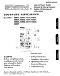
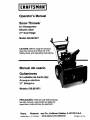
Operator's Manual
Snow Thrower
8,5 Horsepower
Electric Start
27" Dual Stage
Model 536.881851
CAUTION: Before using this product,
read this manual and follow all of its
Safety Rules and Operating Instructions.
Manual del usario
Quitanieves
8,5 caballos de fuerza (hp)
Arranque el_ctrico
27" Biet_pico
Modelo 536.881851
PRECAUCl6N: Antes de usar este producto,
lea este manual y siga todas las reglas de
seguridad e instruccionesde operacibn.
Sears,
Roebuck
198928 Rev. 1 07,19,05 BY
and Co., Hoffman Estates, IL 60179 U.S.A.
www.sears.com/craftsman
Printed in U,S.A.
WARRANTY STATEMENT .. ..
SAFETY RULES ...........
• ,
INTERNATIONAL SYMBOLS • ,
ASSEMBLY ...............
•o
OPERATION ..............
..
MAINTENANCE ...........
..
SERVICE AND ADJUSTMEN1
2
2
4
6
11
18
21
STORAGE ....................
33
TROUBLESHOOTING
TABLE ...
34
REPAIR PARTS ...............
38
ENGINE REPAIR PARTS .......
56
SPANISH (ESPAI;IOL) ..........
63
PARTS ORDERING/SERVICE.,
BACK COVER
UMITED TWO-YEAR WARRANTY ON CRAFTSMAN SNOW THROWER
For two years from the date of pumhase, when this Craftsman Snow thrower is maintained,
lubricated, and tuned up according to the operating and maintenance instructions in the
owner's manual, Sears will repair, free of charge, any defect in material or workmanship.
If this Craftsman Snow thrower is used for commerciai or rental purposes, this warranty applies for only 90 days from the date of purchase.
This warranty does not cover the following:
•
Items which become wom during normal use, such as spark plugs, drive Pelts and shear
pins.
•
Repair necessary because of operator abuse or negligence, including bent crankshafts
and the failure to maintain the equipment according to the instructions contained in the
owner's manual.
WARRANTY SERVICE IS AVAILABLE BY RETURNING THE CRAFTSMAN SNOW
THROWER TO THE NEAREST SEARS SERVICE CENTER IN THE UNITED STATES.
THIS WARRANTY APPUES ONLY WHILETHIS PRODUCT IS IN USE IN THE UNITED
STATES.
This warranty gives you specific legal rights, and you may also have other rights which may
vary from state to state.
Sears, Roebuck and Co., D817WA, Hoffman Estates. IL 60179
IT
MEANSATI'ENTION!II
BECOME
ALERT!!!
YOUR SAFETY
INVOLVED.
LOOK
FOR THIS
SYMBOL TO
POINT OUT
IMPORTANT
SAFETY IS
PRECAUTIONS.
nect the spark
wire
WARNING:
Alwaysplug
disconand place it where it cannot
make contact with spark plug to
prevent accidental starting during:
Preparation, Maintenance, or Storage of your snow thrower.
_
Engine Exhaust, some of its constituents, and
certain vehicle components
contain or emit
chemicals known to the State of California to
cause cancer and birth defects or other reproductive harm.
Battery posts, terminals and related accossorles
contain lead and lead compounds, chemicals
known to the State of California to cause cancer
and birth defects or other reproductive
WASH HANDS AFTER HANDLING.
harm.
IMPORTANT:
Safety standards require operator presence controls to
minimize the risk of injury. Your snow
thrower is equipped wRh such controls.
Do not attempt to defeat the function of
the operator presence control under any
circumstances.
TRAINING
OPERATION
1.
1.
Do not operate this snow thrower if you are
taking drugs or o_er medication which can
cause drowsiness or affect your ability to
operate this snow thrower.
2.
Do not use the snow thrower if you are
mentally or physically unable to operate the
snow thrower safely.
3.
Do not put hands or feat near or under rotating parts. Keep clear of the discharge
opening at all times.
4.
Exercise extreme caution when operating
on or crossing gravel drives, walks or
roads. Stay alert for hidden hazards or
traffic.
,
After striking a foreign object, stop the engine (motor), remove the wire from the
spark plug, thoroughly inspect snow
thrower for any damage, and repair the
damage before restarting and operating
the snow thrower.
Read this operating and service instruction
manual carefully. Be thoroughly familiar
with the controls and the proper use of the
snow thrower. Know how to stop the snow
othrower and disengage the controls quick-
ly.
2.
Never allow children to operate the snow
thrower. Never allow adults to operate the
snow thrower without proper instruction.
3.
Keep the area of operation clear of all persons, particularly small children and pets.
4.
Exercise caution to avoid slipping or falling
especially when operating in reverse.
PREPARATION
1.
Thoroughly inspect the area where the
snow thrower is to be used and remove all
doormats, sleds, beards, wires, and other
foreign objects.
2.
Disengage all clutches before starting the
engine (motor).
6.
3.
Do not operate the snow thrower without
wearing adequate winter outer garments.
Wear footwear that will improve footing on
slippery surfaces.
If the snow thrower should start to vibrate
abnormally, stop the engine (motor) and
check immediately for the cause. Vibration
is generally a warning of trouble.
7.
4.
Handle fuel with care; it is highly flammable.
Stop the engine (motor) whenever you
leave the operating position, before unclogging the auger/impeller housing or discharge chute and when making any
repairs, adjustments, or inspections.
8.
When cleaning, repairing, or inspecting,
make certain the auger/impeller and all
moving parts have stopped and all controls
are disengaged. Disconnect the spark plug
wire end keep the wire away from _ spark
plug to prevent accidental starting.
9.
Take all possible preca_ons when leaving
the snow thrower unattended. Disengage
the auger/impeller,
stop engine (motor),
and remove key.
10.
DO not start or run ongine in enclosed area,
even If doors or windows are open. Exhaust fumes are dangerous (containing
CARBON MONOXIDE, an ODORLESS
and DEADLY GAS).
DO not clear snow across the face of
slopes. Exercise extreme caution when
changing direction on slopes. Do not attempt to clear steep slopes.
a.
Use an approved fuel container.
b.
Never remove fuel tank cap or add fuel
to a running engine (motor) or hot engine (motor).
Fill fuel tank outdoors with extreme
care. Never fill fuel tank indoors.
c.
d.
e.
f.
.
.
7.
Replace fuel cap securely and wipe up
spilled fuel.
Never store fuel or snow thrower with
fuel in the tank inside of a building
where fumes may reach an open flame
or spark.
Check fuel supply before each use, allowing space for expansion as the heat
of the engine (motor) and/or sun can
cause fuel to expand.
For all snow throwers with electric starting
motors use electric starting extension
cords certified CSA/UL Use only with a receptacle that has been installed in accordance with local inspection authorities.
Let engine (motor) and snow thrower adjust to outdoor temperatures before starting
to clear snow.
11.
Always wear safety glasses or eye shields
during operation or while performing an adjustment or repair to protect eyes from
foreign objects that may be thrown from the
snow thrower.
3
12.
Never operate the snow thrower without
proper guards, plates or other safety protective devices in place.
13.
Never operate the snow thrower near enclosures, automobiles, window wells, dropoffs, and the like without proper adjustment
of the snow discharge angle. Keep children
and pets away.
14. Donotoverload
thesnowthrower
capacity
by attempting to clear snow at too fast a
rate.
15.
16.
17.
Never operate the snow thrower at high
transport speeds on slippery surfaces.
Look behind and use care when backing
up.
Never direct discharge at bystanders or
allow anyone in front of the snow thrower.
Disengage power to the collector/impeller
when snow thrower is transported or not in
use.
18.
19.
20.
21.
Use only attachments and accessories approved by the manufacturer of the snow
thrower (such as tire chains, electric start
kits, ect.).
Never operate the snow thrower without
good visibility or light. Always be sure of
your footing and keep a firm hold on the
handles. Walk;never run.
Do not over-reach. Keep proper footing
and balance at all times.
Do not attempt to use snow thrower on a
roof.
MAINTENANCE
1.
2.
Store the snowthrower away from ign_Jon
sources or appliances that have a pilot
light, such as hot water and space beaters,
clothes dryers, etc.... Allow the engine
(motor) to cool before storing in any enclosure,
3.
Always refer to operator's guide instructions for important details if the snow
thrower is to be stored for an extended
period.
4.
Maintain or replace safet_ and instruction
labels, as necessary.
Run the snow thrower a few minutes after
throwing snow to prevent freeze-up of the
auger/impeller.
5.
A
forARNING:
use on sidewalks,
This snow driveways
thrower is
and other ground level surfaces.
Caution should be exercised while using on
steep sloping surfaces.
DO NOT USE
SNOW THROWER ON SURFACES ABOVE
GROUND LEVEL such as roofs of residences, garages, porches or other such
structures or buildings.
AND STORAGE
Check shear bolts and other bolts at frequent intervals for proper tightness to be
sure the snow thrower is in safe working
condition.
IMPORTANT: Many of the following symbols are located on your snow thrower or on literature supplied with the product. Before you operate the snow thrower, learn and understand
the purpose for each symbol.
CONTROL AND OPERATING
SYMBOLS
Slow
Fast
E gine Stop
Electric Start
On
Engine Start
Choke Off
Engine Run
Choke On
G
Throttle
Primer Button
Ignition Key
4
Ignition Off
Ignition On
Drive Clutch
Forward
Push To Engage
Electric Starter
Reverse
Auger Clutch
Fuel
Auger Collector
Oil
Engage
Fuel Oil Mixture
f
Discharge
DOWN
Discharge
UP
Discharge LEFT
Discharge
RIGHT
0
Weight Transfer
Lift Handle To
Engage
Weight Transfer
Depress Pedal
To Disengage
Transmission
Ignition Key
Insert To Run,
Pull Out To Stop.
SafetyWarningSymbols
A
DANGER
Thrown Objects.
Keep Bystanders Away.
IMPORTANT
Read Owner's Manual
Before Operating
This Machine.
WARNING
Hot Surface
m-+
DANGER
Thrown Objects.
Keep Bystanders Away.
DANGER
Avoid Injury From
Rotating Auger. Keep
Hands, Feet And
Clothing Away.
STOP
5
WARNING
DANGER
Stop The Engine Before
Unclogging Discharge Chutel
CONTENTS OF PARTS BAG (ACTUAL SIZE)
1 - Owner's Manual (not shown)
1 - Packet of Fuel Stabilizer (not shown)
1 - Warranty Card (not shown)
*Non-Assembly Parts, found in toolbox located on belt cover
*2- Shear Pins
A
safety
ARNING:
glasses
Always
or eye
wear
shields
while assembling snow
thrower.
TOOLS REQUIRED FOR
ASSEMBLY
1 - Knife to cut carton
2 - 1/2 inch wrenches
Figure 1
(or adjustable wrenches)
2 - 9/16 inch wrenches
(or adjustable wrenches)
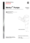
Figure 1 shows the snow thrower in the
shipping position.
Figure 2 shows the snow thrower completely assembled.
References to the right or left hand side
of the snow thrower are from the viewpoint of the operator's position behind
the unit.
2 - 3/4 inch wrenches
(or adjustable wrenches)
1 - Pliers (to spread cotter pin)
1 - Screwdriver
1 - Measuring tape or ruler
TO REMOVE SNOW THROWER
FROM CARTON
,
cable back away from the motor
frame.
Locate all parts packed separately
and remove from the carton.
Auger Drive Lever n
"_
_ L_-------.-
NOTE: Place fuel stabilizer in a
safe place untilneeded for storage.
,
_
Traction
Drwe Lever
_" Clutch Cable
Remove and discardthe packing
materialfrom around the snow
thrower.
nk Assembly
3. Cut down all four comers of the carton and lay the panels flat.
4. Cut the straps that secure the axle
to the pallet.
5.
For shipping purposes, the height
adjust skids are attached to the
pallet. Remove the screw that secures each height adjust skid to
the pallet. See Figure 2.
6.
Roll snow thrower off the pallet by
pulling on the lower handle. CAUTION: DO NOT back over control
cables.
7,
Remove all packing material from
the unit.
8.
Cut ties securing the clutch control
cable to the lower handle and lay
ShifteJ
'__r_
[_ft_tector
Lever
Height
Adjust
Skid
Scre_
7
Figure2
TO ASSEMBLE
CRANK
THE HANDLE
ASSEMBLY
AND
6.
1. Cut tie holding shift rod to lower
handle and move shifter to the first
forward gear.
2. Cut and discard the plastic tie that
secures the crank assembly.
3. Loosen, but do not remove, the
screws, flatwashers, Iockwashers,
and hex nuts in the upper holes of
the lower handle. See Figure 3.
4. Remove the fasteners and the eyebolt from the lower holes of the lower handle See Figure 5,
Install the fasteners that were removed in step 4. DO NOT tighten
until all bolts are in place.
Left Side Of
3/8" Nylon
htHand Side
Loosen,
but do not
remove
Eye Bolt
Flatwasher
Figure 5
11/32"
Fiatwasher
7. Attach the crank rod to the universal
joint assembly with the hair pin. See
Figure 6.
5/16" Hex
5/16"
Screw
8. Tighten nut on eye bolt. Make sure
eye bolt is properlyaligned and the
crank can freely rotate.
5/1_' _
Lockwasher
Figure 3
NOTE:
9. "13ghtenall handle and panel bolts.
Make sure the cables are
not caught between the upper and
lower handle.
.
Raise the upper handle intooperating position.
NOTE: If the cables have become disconnectedform the drive levers, reinstallthe cables as shown in Figure 4.
Lever
"Z" Fitting
_,
Universal
Crank ::led
Figure 6
Control Cable
Figure 4
8
NOTE: If the cables have become disconnected, connect cables as shown in
Figure 7.
Traction Drive Cable
Auger Drive Cable
Figure 7
HOW TO ASSEMBLE THE CHUTE DEFLECTOR
1. Remove the carriage bolt. See
Figure 8.
2. Raise the chute deflector into operating position.
3. Fasten chute deflector to flange
with carriage bolt, Make sure to
installwith head of carriage bolt on
the inside of the flange.
4. Fasten with washer and Iocknut.
Chute Deflector
Nut
Operating_
Position
5. 13ghten Iocknut securely.
NOTE: Make sure all carriage
bolts in flange are tight. DO NOT
OVERTIGHTEN,
Carriage Bolt
Flange
Figure 8
HOW TO SET THE SKID HEIGHT
Your snow thrower is equipped with
height adjust skids on the outside of the
auger housing. To adjust the skid
height for different conditions, see To
Adjust Skid Height paragraph in the
Service And Adjustment section.
HOW TO SET THE LENGTH OF THE CABLES
The cables were adjusted at the factory
and no adjustments should be necessary. However, after the handles are put
in the operating position, the cables can
be too tight or too loose. If an adjustment is necessary, see =How To Check
And Adjust The Cables" in the Service
And Adjustment section.
CHECKLIST
Before you operate your new snow
thrower, to ensure that you receive the
best performance and satisfaction from
this quality product, please review the
following checklist:
shipped with the starter cord plugged
into the engine. Before operating, unplug the starter cord from the engine.
While learning how to use your snow
thrower, pay extra attention to the following important items:
P" All assembly instructionshave been
completed.
v"
The discharge chute rotates freely.
_'
P" No remaining loose parts in carton.
P" Check the fasteners. Make sure all
fasteners are tight.
_" Check the air pressure of the tires.
Correct air pressure is from 14 to 17
PSI. See the side of the tire for maximum inflation. Do not exceed maximum inflation.
I!
Engine oil is at proper level. Use a
high quality detergent oil classified
=For Service SG, SH, SJ, SL, or
higher".
_" Make sure gas tank is filled properly
with clean, fresh, unleaded gasoline
with a minimum of 85 octane.
/I
Become familiar with all controlstheir location and function. Operate
controls before starting engine.
On electric start models, the unit was
lO
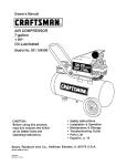
KNOW YOUR SNOW THROWER
READ THIS OWNER'S MANUAL AND SAFETY RULES BEFORE OPERATING
YOUR SNOW THROWER. Compare the illustrations with your SNOW THROWER
to familiarize yourself with the location of various controls and adjustments. Save
this manual for future reference.
Drive Lever
(left hand)
Auger
Drive Lever
(right hand)
Choke
Control
Primer
Button
Gas
Speed
Cap
Shifter
Lever
Crank
j
Assembly
Chute
Deflector
Discharge
Chute
Safety
Key
Stop
Switch
Recoil
Starter
Handle
Electric
Start
Button
Height
Adiust
Skid ,'------
Auger Drive Lever - Startsand stops
the auger and impeller(snow gathering
and throwing)
Shear Pin
Scraper Bar
Figure 9
Safety Key - Must push in to start the
engine.
Recoil Starter Handle - Starts the engine manually.
Choke Control - Used to start a cold
engine.
Traction Drive Lever - Propelsthe
snowthrower forwardand in reverse.
Speed Shifter Lever - Selects the
speed of the snow thrower (6 speeds forward and 2 speeds reverse).
Primer Button - Injects fuel directly into
the carburetor manifold for fast starts in
cold weather.
Crank Assembly - Changes the direction of snow throwing through the discharge chute.
Electric Start Button - (if so equipped)
Used to start the engine using the 120 V
electric starter.
Chute Deflector - Changes the distance
the snow is thrown.
Shear Pin - Shear pinsare designedto
break (to protectthe machine)if an obiect becomes lodgedin the auger housing.
Toolbox - Spare shear pinsand spacers
are locatedin toolbox.
Discharge Chute - Changes the height
and direction the snow is thrown.
Height Adjust Skid - Adjusts the ground
clearance of the auger housing.
11
The operation of any snow thrower can
result in foreign objects being thrown
HOW TO MOVE FORWARD AND
BACKWARD
into the eyes, which can result in severe eye damage. Always wear safety
glasses or eye shieldswhile operating
the snow thrower.
1. TO shift, release the traction drive
lever (left hand) and move the
speed shifter lever to the speed you
desire. Ground speed is determined by snow conditions. Select
the speed you desire by moving the
speed shifter lever left into the appropriate notches on the shift lever
plate:
Speeds 1,2 - Wet, Heavy
Speed 3 - Light
We recommend standard safety
glasses or a wide vision safety mask for
over your glasses.
Manual
before
operating
ARNING:
Read
Owner's
machine. Never direct discharge toward bystanders. Stop the
engine before unclogging discharge
chute or auger housing and before
leaving the machine.
A
Speed 4 - Very Light
Speed 5,6 - Transport only
2. Engage the traction drive lever (left
hand). As the snow thrower starts
to move, maintain a firm hold on the
handles, and guide the snow thrower along the clearing path. Do not
attempt to push the snow thrower.
3. To move the snow thrower backward, move the speed shifter lever
right into first or second reverse and
engage the traction drive lever (left
hand).
TO STOP YOUR
SNOW THROWER
1. To stop throwing snow, release the
auger drive lever.
2. To stop the wheels, release the
traction drive lever.
3. To stop the engine, pull out the
safety key.
IMPORTANT: Do not move the speed
shifter lever while the traction lever is
CAUTION: To stop the engine, do not
move the choke control to CHOKE
down.
position. Backfire or engine damage
TO THROW SNOW
1. Push down the auger driver lever
(right hand).
2. Release to stop throwingsnow.
can occuh
TO CONTROL SNOW DISCHARGE
1. "rum the chute control rod to set the
direction of the snow throwing.
2.
TO USE WHEEL LOCKOUT PIN
Loosen the wing knob on the chute
deflector and move the deflector to
set the distance. Move the deflector
(Up) for more distance, (Down) for
less distance. Then tighten the
wing knob (See Figure 10).
,
The right hand wheel is secured to
the axle with a klick pin. This unit
was shipped with this klick pin in the
locked position (through wheel
hole). See Figure 11.
Klick Pin
Wing Knob
Locked
Position
ure 10
2-Wheel
Drive
Figure 11
12
2.
NOTE: Do not check the level of the
oil while the engine runs,
2. Remove the oil fill cap/dipstick and
wipe with a clean cloth.
3. Insert the oil fill cap/dipstick and
turn clockwise to tighten.
4. Remove the oil fill cap/dipstick and
check the oil.
For ease of maneuverability in light
snow conditions, disconnect the
klick pin from the wheel locked
position and push into the single
wheel drive position (unlocked axle
hole only). See Figure 12.
K]ick Pin
5.
Unlocked
Position
If necessary, add oil until the oil
reaches the FULL mark on the oil fill
cap/dipstick (see Figure 13). Do not
add too much oil.
•OII FillCap/Dipstick
Single Wheel
Drive
Figure 12
%
NOTE: Make sure that the klick pin is
in the single wheel drive positionof the
axle only and not throughthe locked
position.
NOTE:
level
must be at the
Full mark
Figure 13
BEFORE STARTING THE ENGINE
6. "Nghten the fill cap/dipstick securely
each time you check the oil level.
NOTE: Synthetic oil can assist with
starting in extreme cold temperatures.
Synthetic 5W30 is acceptable for all
temperatures. DO NOT mix oil with
Before you service or start the engine, familiarize yourself with the
snow thrower. Be sure you understand the function and location of all
controls.
tw
.
,
4.
.
Check the tension of clutch cable
before starting the engine. See To
Adjust The Control Cable paragraph in the Service & Adjustments section of this manual.
gasoline.
FILL GAS:
This engine is certified to operate on
gasoline. Exhaust Emission Control
System: EM (Engine Modifications).
Be sure that all fasteners are tight.
Make sure the height adjust skids
are properly adjusted. See To Adjust Skid Height paragraph in the
Service & Adjustments section of
this manual.
fuels
(called Alcohol
gasohol blended
or
ARNING:
those using ethanol or
methanol) can attract moisture
which leads to separation and
formation of acids during storage.
Acidic gas can damage the fuel system of an engine while in storage.
_
Check tire pressure (14-17
pounds). Do not exceed maximum
amount of pressure.
NOTE: To avoid engine problems, the
fuel system must be emptied before
storage for 30 days Or longer. Start the
engine and let it run until the fuel lines
and carburetor are empty. Use fresh
fuel next season. See the Storage
section in this manual for additional information.
CHECK THE OIL:
NOTE: The engine was shippedfrom
the factory filled with oil. Check the level of the oil, Add oil as needed.
To Add Oil
1, Make sure the unit is level.
13
leaded gasoline. Make sure that the
containeryou pourthe gasolinefrom is
clean and free from rust or other foreign
particles. Never use gasolinethat may
be stale from long periodsof storage in
the container.
Never use engine or carburetorcleaner
productsin the fuel tank or permanent
damage may occur.
Fill the fuel tank only witha fresh, clean,
unleaded regular,unleaded premium,or
reformulatedautomotivegasolinewitha
minimumof 85 octane. DO NOT use
A
•
Always fill fuel tank outdoors and
use a funnel or spout to prevent
spilling.
Make sure to wipe up any spilled
fuel before stating the engine,
Store gasoline in a clean, approved container and keep the
cap in place on the container.
•
•
Keep away from open flame or an
electrical spark and do not smoke
while filling the fuel tank.
TO STOP ENGINE
TO START ENGINE
Be sure that the engine oil is at FULL
mark on dipstick, The snow thrower engine is equipped with a 120 volt A,C.
electric starter and recoil starter. Before
starting the engine, be certain that you
have read the following information.
If engine floods, set the choke to the
OPEN/RUN position and crank until the
engine starts.
CAUTION: To stop the engine, do not
move the choke control to CHOKE
position. Backfire or engine damage
can occuh
1.
Never fill the tank completely. Fill
the tank to approximately 1-1/2"
below the top of the tank opening
to provide space for expansion of
fuel.
mable.
Always
use caution
ARNING:
Gasoline
is flamwhen handling or storing
gasoline.
• Turn engine off and let engine
cool at least two minutes before
removing the gas cap.
• Do not fill fuel tank while snow
thrower is running, when it is hot,
or when snow thrower is in an enclosed area.
•
•
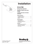
Push the stop switch to the OFF
position.
Stop Switch
of ARNING:
the starter Rapid
cord retraction
(kickback) will pull your hand or
arm toward the engine faster than
you can let go of the starter cord.
Broken bones, fractures, bruises, or
sprains could result.
• When starting the engine, slowly pull the starter cord until resistance is felt. Then, rapidly
pull the starter cord.
• Before starting the engine, remove all external equipment/engine loads.
• Make sure components; such as
impellers, pulleys or sprockets,
are securely attached.
A
Figure 14
2.
Pull out the safety
key.
Safety Key
Figure 15
14
If your system is grounded and s
three-hole receptacle is not available at the point your starter will
normally be used, one should be
installed by a licensed electrician.
When connecting 120 volt AC
"Power Cord", always connect the
cord to the Switch Box on the engine first, then plug the other end
into the three-hole grounded receptacle. When disconnecting
"Power Cord", always unplug the
end In the three-hole grounded receptacle first.
equipped
three-wire
,_
WARNING: with
Thea starter
is
power cord and plug and is
designed to operate on 120 volt AC
household current. It must be properly grounded at all times to avoid
the possibility of electrical shock
which may be injurious to operator.
Follow all instructions carefully
as sat forth in the "To Start Engine" section.
Determine that your house wiring
is a three-wire grounded system.
Ask a licensed electrician if you
are not sure. If your house wire
system is not a three-wire system,
do not use this electric starter under any conditions.
Choke Knob
Safety Key
Recoil Starter
Handle
Stop Switch
How To Start
A Cold
Engine
Push the stop switch to the ON
position (see Figure 16).
3.
4.
Push in the safety key.
Rotate the choke knob to the
CHOKE position.
Figure 16
6. Push the primer button as specified below. Remove finger from
primer button between pushes.
•
Push two times if temperature is
15 ° F (-9 ° C) or higher.
•
Push four times if temperature is
below 15° F (-9 ° C).
7. (E/ecfric Start) Push down on the
starter button u_l the engine starts.
To prolongthe life of the starter, do not
crank for more than 5 seconds at a
time. Wait one minute between starts
to allow the starter motor to cool.
(Recoil Start) Slowly pull the recoil
starter handle until resistance is
1. Be sure auger drive and traction
drive levers are in the disengaged
(RELEASED) position.
2.
Power Cord
Receptacle
5. (Electric Start) Plug the power cord
into the starter motor on the engine. Plug the other end of power
cord into a three-hole, grounded
120 VOLT, AC receptacle.
,
15
felt and then pull rapidly to start the
,
engine. Do not allow the recoil
starter handle to snap back. Slowly
retum the recoil starter handle.
9.
2.
If the engine does not start in 5 or 6
tries, See Difficult Starting in the
='l'mubleshooting Table".
.
10. Allow the engine to warm up for
several minutes. As the engine
warms up, adjust the choke knob
toward the RUN position. Wait until
the engine runs smoothly before
each choke adjustment.
11. (Electric Start) First disconnect
power cord from receptacle. Then,
disconnect the power cord from the
starter motor.
How To Start A Warm
With engine off, allow engine to cool
for several minutes.
Pull starter rope very slowly until resistance is felt, then stop. Allow the
starter rope to recoil. Repeat three
times.
With the engine not running, wipe all
snow and moisture from the carburetor cover in area of controls and
levers. Also, move the choke control
and starter handle several times.
gine indoorsNever
or in run
enclosed,
WARNING:
enpoorly ventilated areas. Engine exhaust contains CARBON
MONOXIDE, AN ODORLESS AND
DEADLY GAS. Keep hands, feet,
hair and loose clothing away from
any moving parts on engine and
snow thrower.
A
Engine
If restarting a warm engine after a short
shutdown, leave the choke lever in the
off position and do not push the primer
button, if the engine fails to start, follow
the Cold Start instructions.
Frozen Starter
If the starter is frozen and will not turn
the engine, follow the steps below.
1. Pull as much starter rope as possible out of the starter.
•
Engine parts, especially the muffler, become extremely hot. Severe thermal burns can occur on
contact. Allow the engine to cool
before touching.
•
Never allow children to operate
the snow thrower. Never allow
adults to operate the snow thrower without proper instruction.
Keep the area of operation clear
of all persons, particularly small
children and pets.
Never leave the snowthrower unattended while the engine is running. Anyone operating the engine or equipment must carefully
read and understand the operating instructions.
•
2.
Release the starter handle and let it
snap back against the starter. Repeat until the engine starts.
Warm engines will cause condensation
in cold weather. To prevent possible
freeze-up of recoil starter and engine
controls, proceed as follows after each
snow removal job.
•
16
TO REMOVE SNOW FROM AUGER
stickto remove snowfrom the auger
housing.
remove snow
or attempt
debris
. to ARNING:
Do not
that may become lodged in
auger with your hands. Use the
cleaning stick to remove snow or
debris.
•
Release auger drive lever.
•
Remove (do not turn) safety key.
•
Disconnectspark plug wire.
•
Do not place your hands in the auger or dischargechute. Use the
cleaning stickto remove snow.
A cleaning stick is attached to the top of
the auger housing. Use the cleaning
SNOW THROWING TIPS
1. For maximum snow thrower efficiency in removing snow, adjust ground
speed. Go slower in deep, freezing
or wet snow. If the wheels slips, reduce forward speed.
2. Most efficientsnow throwingis accomplishedwhen the snow is removed immediately after if falls.
3. For complete snow removal, slightly
ovedap each path previouslytaken.
4. The snow should be discharged
down windwhenever possible.
5.. For normal usage, set the skids so
that the scraper bar is 1/8" above
the skids. For extremely hardpacked snow surfaces, adjust the
skids upward so that the scraper
bar touchesthe ground.
6. On gravel or crushed rock surfaces,
set the skids at 1-1/4" below the
scraper bar. See To Adjust Skid
Height paragraph in the Service &
Adjustments section of this manual. Rocks and gravel must not be
picked up and thrown by the machine.
.
.
After the snow throwing job has
been completed, allow the engine to
idle for a few minutes, which will
melt snow and accumulated ice off
the engine.
Clean the snow thrower thoroughly
after each use.
9. Remove ice and snow accumulation
and all debrisfrom the entire snow
thrower, and flushwith water (if possible) to remove all salt or other
chemicals. Wipe snow thrower dry.
17
CUSTOMER
RESPONSIBIUTIES
SERVICERECORDS
Fillindatesasyou
completeregular
service.
Before
Each
Use
Often
Every Every
8
25
Hours Hours
Change Engine Oil
Every
Each_
IO0
Hours Season
Before
Storage
_/
Check and Clean Spark
Plug
"_
Clean and Inspect
SparkArrestor
Check Fuel
Every
50
Hours
_"
"_
Auger DriveBelt *
_/
ii
• Adjust after 2 to 4 hours of use,
GENERAL RECOMMENDATIONS
The warranty on this snow thrower does
not cover items that have been subjected
to operator abuse or negligence. To receive full value from the warranty, the operator must maintain the snow thrower as
instructed in this manual.
Some adjustments will need to be made
periodically to properly maintain your
snow thrower.
Maintenance, replacement, or repair of the
emission control devices and systems can
be performed by any non-road engine repair establishment or individual. Regular
maintenance will improve the performance
and extend the life of the engine.
AFTER EACH USE
•
Run the machine to clear the auger
of snow.
•
To prevent freezing of the auger or
controls, remove all snow and slush
from the snow thrower.
•
Check for any loose or damaged
parts.
_ghten any loose fasteners.
•
•
•
•
flywheel
hammer
ARNING:withDoa not
strike or
thea
hard opject, ff done, the flywheel can shatter during operation.
Do not tamper with the governor
spring, links or other parts to increase engine speed.
A
18
Check and maintain the auger.
Check controls to make sure they
are functioning properly.
If any parts are worn or damaged,
replace immediately.
ENGINE SPECIFICATIONS
SNOW THROWER
AUGER DRIVE BELT
HORSEPOWER
8.SHP
DISPLACEMENT
249 cc
BORE
75rnm (2.970 in.)
STROKE
56ram (2.205 in.)
GASOLINE
CAPACITY
3 quarts
(unleaded)
OIL CAPACITY
(18 oz capacity)
5W30
SPARK PLUG:
VALVE
CLEARANCE:
ter (See to "Belt Adjustment" in the
Service and Adjustment section),
CHAIN LUBRICATION
EVERY 25 HOURS
1.
Position speed selector lever in first
(1) forward gear.
2. Stand the snow blower up on the
auger housing end.
NOTE: When the crank case if
filled with oil, do not leave the
snow blower standing up on the
auger housing for an extended
period of time,
Champion RJ19LM
(Gap .030 in.) or
equivalent
Intake: 0.004-0.006
in.
Exhaust: 0.009-0.011 in.
ARMATURE
AIR GAP:
POWER
Adjust the auger drive belt after the first
2 to 4 hours of use, again about midseason and twice each season thereaf-
0.010-0.014
in.
3.
4.
Remove the bottom panel.
Lubricate the chains with a chain
type lubricant.
5. For storage, wipe the hexshaft and
sprockets with 5W30 motor oil.
RATINGS
The power ratings for an individual
engine model are initially developed by
starting with SAE (Society of Automotive Engineers) code J1940 (Small
Engine Power & Torque Rating Procedure) (Revision 2002-05). Given both
the wide array of products on which our
engines are placed, and the variety of
environmental issues applicable to
operating the equipment, it may be that
the engine you have purchased will not
develop the rated horsepower when
used in a piece of power equipment
(actual =on-site" power). This difference
is due to a variety of factors including,
but not limited to, the following: differences in altitude, temperature, barometric pressure, humidity, fuel, engine
lubrication, maximum governed engine
speed, individual engine to engine
variability, design of the particular piece
of power equipment, the manner in
which the engine is operated, engine
run-in to reduce friction and clean out of
combustion chambers, adjustments to
the valves and carburetor, and other
factors. The power ratings may also be
adjusted based on comparisons to
other similar engines utilized in similar
applications, and will therefore not
necessarily match the values derived
using the foregoing codes.
NOTE: Clean all excess grease or
oil found on the rubber friction
wheel or the disc drive plate.
CAUTION: Do not allow grease or
oil to contact the rubber friction
wheel or the disc drive plate,
6.
Install the bottom panel.
Chain
AUGER GEAR BOX
The auger gear box is lubricated at the
factory and should not require additional lubrication. If for some reason the
lubricant should leak out, have auger
gear case checked by a competent repairman.
19
ENGINE
Change the oil every fifty (50) hours or
at least once a year if the snow thrower
is not used for fifty (50) hours.
LUBRICATION
Check the crankcase oil level before
starting the engine and after each eight
(8) hours of continuous use. See
Figure 18. Add S.A.E. 5W30 motor oil
as needed. Synthetic 5W30 is acceptable for all temperatures. Tighten fill
cap/dipstick securely each time you
check the oil level.
Oil Fill Cap/DipsUck
TO CHANGE ENGINE OIL
1. Position the snow thrower so that
the oil drain plug is at the lowest
point on the engine.
2. When the engine is warm, remove
the oil drain plug and the oil fill
cap/dipstick (see Figure 18). Drain
the oil into a suitable container.
After draining all the oil, reinstall the
oil drain plug securely.
4. Fill the engine crankcase with the
recommended motor oil, pouring
slowly. DO NOT OVERFILL. See
=1"oAdd Oil" in the Operation Section.
,
Oil
NOTE:
Figure 18
SPARK PLUG
.
Check the spark plug every twentyfive (25) hours. Replace the spark plug
if the electrodes are pitted or burned, if
the porcelain is cracked, or every 100
hours of use.
Before installing the spark plug,
coat the threads lightly with oil for
easy removal, Tighten the spark
plug to a torque of 15 foot-pounds.
Feeler Gauge
0.030"
1. Make sure the spark plug is clean.
Clean the spark plug by carefully
scraping the electrodes (do not
sand blast or use a wire brush).
2. Check the spark plug gap with a
feeler gauge and reset gap to 0.30"
if necessary. See Figure 19.
Spark Plug
Figure 19
2O
raise the adjustable skids. _ghten
the mounting nuts. See Figure 20.
NOTE: For rocky or uneven surfaces,
raise the front of the snow thrower by
moving the skids down.
nect
the spark
plug disconwire and
A
ARNING:
Always
place it where it cannot
make contact with spark plug to prevent accidental starting when making any adjustments or repairs.
maintain
groundto
ARNING:proper
Be certain
clearance for your particular
area to be cleared. Objects such as
gravel, rocks or other debris, if
struck by the impeller, may be
thrown with sufficient force to cause
personal injury, property damage or
damage to the snow thrower.
A
TO ADJUST SKID HEIGHT
This snow thrower is equipped with two
height adjustment skids, located on
the outside of the auger housing. See
Figure 20.
These skids elevate the front of the
snow thrower.
TO ADJUST SCRAPER BAR
Nuts
.
After considerable use, the metal scraper bar will have a definitewear pattem.
The scraper bar in conjunctionwiththe
skids shouldalways be adjusted to allow 1/8" between the scraper bar and
the sidewalk or area to be cleaned.
O
1. Positionthe snow thrower on a level
surface.
Height Adjust Skid
Figure 20
.
For normal hard surfaces, such as a
paved driveway or walk, adjust the
skids as follows.
1.
.
Position the snow thrower on a level
surface.
Make sure both tires are equally inflated. Proper tire pressure is 14 to
17 PSI. See side of tire for maximum inflation. Do not exceed maximum sidewall pressure on tire.
3. Loosen the carriage bolts and nuts
securingthe scraper bar to the auger housing.
Make sure both tires are equally inflated. Proper tire pressure is 14 to
17 PSI. See side of tire for maximum inflation. Do not exceed maxi-
4. Adjust the scraper bar to the proper
position.
mum sidewall pressure on tire.
5. "13ghten
the carriage boltsand nuts,
making sure that the scraper bar is
parallel with the workingsurface.
3. Place the extra shear bolts supplied
with the unit under each end of the
scraper bar next to the adjustable
skids.
1
4. Loosen the mounting nuts that hold
the adjustable skids. To bring the
front of the snow thrower down,
21
For extended operation, the scraper
bar may be reversed. If the scraper
bar must be replaceddue to wear,
remove the carriage boltsand nuts
and installa new scraper bar.
HOW TO REMOVE
THE SNOW HOOD
Mounting Screws
Snow Hood
To access the spark plug, the snow
hood must be removed as follows:
Spark
Plug
1. Remove the choke control knob
(see Figure 21).
2.
Remove the safety
key.
3.
Remove the mounting
(see Figure 22).
4.
Slowly remove the snow hood.
Make sure that the primer button
hose and the Ignition wire are not
disconnected.
screws
5. The spark plug can now be accessed.
6. To install the snow hood, first make
sure that the primer button hose
and the ignition wire are connected.
igure 22
7.
Mount the snow hood to the engine
and secure with the mounting
screws (see Figure 22).
8. Connect the choke control knob
with the choke shaft on the carburetor (see Figure 23 and Figure 24).
Make sure the choke control knob is
properly installed. If the choke control knob is not installed correctly,
the choke will not operate.
Choke
Control Knob
9. Install the safety key.
Choke
Choke ShaR
Figure 23
Key
Carburetor
Figure 21
Figure 24
22
BELT ADJUSTMENT
Traction Drlve Belt
The tractiondrive belt has constant
spring pressure and does not require
an adjustment. If the traction drive belt
is slipping, replace the belt. See =How
To Replace The Belts" in the Service
And Adjustment section.
.
Auger Drive Belt
If your snow blower will not discharge
snow, check the control cable adjustment. If it is correct, then check the
condition of the auger drive belt. If it is
damaged or loose, replace it (see "How
To Replace The Belts" in this section of
the manual).
1.
Have someone engage auger drive
clutch. Check tension on belt (opposite idler pulley). Belt shoulddeflect about 1/2 inch (12.5 mm) with
moderate pressure (Figure 26). You
may have to move idler pulley more
than once to obtain the correcttension.
Auger
t
Idler.....-,.([
Pulley 7
,_
EDngiVnee
-_
Pulley
J _O
",\_
..i',,_ I''_
"_
",\
1/2 inch
(12.5mm)
Deflection
Disconnect spark plug wire.
• Engaged /.___.___
2. Remove screw from belt coven
Remove belt cover (see Figure 25).
Figure 26
6.
.
Reinstall belt cover.
Whenever belts are adjustedor replaced, the cables will need to be
adjusted. (See Cable Adjustmentin
this section of the manual).
8. Attach the spark plug wire.
25
.
Loosen nut on auger idler pulley
and move auger idler pulley towards
belt about 1/8 inch (3 mm) (see
Figure 29).
4. "13ghtennut.
23
HOW TO REPLACE THE BELTS
two bolts, The auger housing and
the motor box can now be split
apart for removal of the belt (see
Figure 28).
The drive belts are of special construction and must be replaced with original
equipment replacement belts available
from your nearest Sears service center.
.
Some steps requirethe assistance of a
second person,
How To Remove the Auger Drive Belt
if the auger drive belt is damaged, the
snow thrower will not discharge snow.
Replace the damaged belt as follows.
10. Install the new auger drive bolt
onto the auger drive pulley.
NOTE: To assemble the auger
housing to the motor box, have
someone hold the auger clutch
lever in the ENGAGED position,
This will move the idler arm and
pulley enough to allow the auger
drive pulley to move back into
position.
1. Disconnect the spark plug wire.
2.
Loosen the bolts on each side of
the bottom panel (see Figure 27).
3.
Remove the bottom panel.
Bolt
'
i%
"_,
",_'_
_
n
Bottom
, Panel
l
Auger
_
.,_,ousing
Remove the old auger drive bolt
from the auger drive pulley, Replace the auger drive belt with an
original factory replacement belt
available from an authorized service
center (see Figure 29).
11. Assemble the auger housing to the
motor box with the four bolts that
were removed in step 8. Tighten the
bottom two bolts,
12. install the auger drive belt onto the
engine pulley.
13, Slip the auger drive bolt under the
idler pulley.
14. Adjust the auger drive bolt, See
=How To AdjustThe Auger Drive
Belt"in the Service And Adjustment
section.
Figure 27
4.
5.
Remove screw from belt cover,
Remove the belt cover (see
Figure 25),
Loosen the belt guide. Pull the belt
guide away from the auger drive
pulley (see Figure 29).
6.
Pull the idler pulley away from the
auger drive belt and slip the auger
drive belt off of the idler pulley.
7.
Remove the auger drive belt from
the engine pulley. To remove the
auger drive belt, the engine pulley
may have to be partially rotated.
8,
15. Adjust the bolt guide. See =How To
Adjust The Belt Guide" in the Service And Adjustment section.
16. Install the bolt cover. Tighten
screw (See Figure 25).
17. Check the adjustment of the cables.
See "How To Check And Adjust The
Cables" in the Service And Adjustment section.
18, Install the bottom panel (see
Figure 27).
19. Tighten the bolts on each side of
the bottom panel,
Remove the top four bolts that hold
together the auger housing and
the motor box, Loosen the bottom
20, Connect the spark plug wire,
24
Remove
Bolts
Motor Box
Auger
Housing
Figure 28
Traction Drive Belt
/
Belt Guide
Auger Drive Pulley
Traction Drive
Auger Drive Belt
TractionDrive
Spring
Traction
Drive Belt
E-Ring
Traction
Drive Pulley
Swing Plate
Axle Rod
Engine
Pulley
Figure 29
25
How To Remove
The Traction Drive Belt
plate is properly secured (see
Figure 30),
If the snow thrower will not move forward, check the traction drive belt for
wear or damage. If the traction drive
belt is worn or damaged, replace the
belt as follows,
1. Disconnectthe spark plug wire,
2. Remove the auger drive belt. See
=How To Remove The Auger Drive
Belt"in the Service And Adjustment
section.
3.
Remove the e-ring from one end of
the swing plate axle rod, Remove
the swing plate axle rod to allow
the swing plate to pivot forward (see
Figure 29).
4.
Remove the traction drive spring.
5.
Remove the old traction drive belt
from the traction drive pulley and
from the engine pulley. Replace
the traction drive belt with an original equipment replacement belt
available from a Sears service center.
Alignment Tabs
NOTE: If the drive will not engage
after the traction drive belt has
been replaced, then check to
make sure that the swing plate is
positioned between the alignment tabs.
11. Install and adjust the auger drive
belt. See "How To Remove The Auger Drive Belt" in the Service And
Adjustment section.
12. Adjust the belt guide. See =How To
Adjust The Belt Guide" in the Service And Adjustment section.
6. Install the new traction drive belt
onto the traction drive pulley and
onto engine pulley.
7.
13. Install the bottom panel (see
Figure 27).
Make sure the traction drive idler
pulley is propedy aligned with the
traction drive belt.
8.
Attach the traction
9.
install the swing plate axle rod and
secure with the e-ring removed
earlier,
14. Tighten the bolts on each side of
the bottom panel.
drive spring.
10. The bottom of the awing plate must
be positioned between the alignment tabs. Make sure the swing
Figure 30
15. Install the belt cover. Tighten
screw (see Figure 25).
16. Check the adjustment of the cables.
See =How To Check And Adjust The
Cables" in the Service And Adjustmeht section.
26
17. Connect the spark plug wire.
BELT GUIDE ADJUSTMENT
I.
Remove spark plug wire.
2.
3,
Have someone engage auger drive.
Measure the distance between the
"Z" Fitting
belt guide and belt. The distance
should be 1/8 inch (3.175 mm) for
guide. See Figure 31.
Figure 32
Belt Guide
1/8 Inch
(3.175 rnm)
Auger Idler __
Pulley
Engaged
"-'V
_-d
.
\\
Auger Drive Cable Adjustment
_
1. Run the engine until the fuel tank is
empty and the engine stops.
Figure 31
.
q
6.
The center of the "Z" fitting should
be between the center and top of
the hole in the clutch lever. Adjust
either the auger drive cable or the
traction drive cable as as necessary
according to the following instructions.
if adjustment is necessary, loosen
belt guide mounting bolt. Move belt
guide to the correct position. Tighten mounting bolt.
Reinstall belt cover,
2.
Stand the snow thrower up on the
front end of the auger housing.
3.
Push cable through spring to expose the threaded portion of the
cable (see Figure 33).
Reconnect spark plug wire,
HOW TO CHECK AND
ADJUST THE CABLES
Square
The cables are adjusted at the factory
and no adjustment should be necessary. If the cables have become
stretched or are sagging adjustmentwill
be necessary.
Whenever belts are adjustedor replaced, the cables will need to be adjusted.
End _
\
Cable Spring
To check for correct adjustment, unhook "Z" fitting at clutch lever (see
L_J
_
Locknut
Figure 33
Figure 32).
1, Move clutch lever to the
position (just contacting
bumper). Holding cable
position of fitting to hole
full forward
plastic
tight, note
in clutch le-
.
ver,
27
Hold square end of threaded portion
with pliers and adjust Iocknut in or
out until correct adjustment is
reached. Pull cable back through
spring and connect cable.
TRACTION DRIVE CABLE ADJUSTMENT
1. Run the engine until the fuel tank is
empty and the engine stops.
2. Stand the snow thrower up on the
front end of the auger housing.
3. Loosen the bolts on each side of
the bottom panel (see Figure 34).
Bolt
o
8.
Bottom Panel
Remove the "Z" hook from the
cable adjustment bracket. Move
the "Z" hook down to the next adjustment hole,
9.
Pull the traction drive cable up
through the cable adjustment
bracket.
10, Put the cable boot over the cable
adjustment bracket.
11. Install the "Z" hook to the traction
drive lever (see Figure 32),
12, To check the adjustment, depress
the drive lever and check the length
of one of the drive springs, In correct adjustment, the length of the
drive spring is:
minimum 3" (76 ram,)
maximum 3-3/8" (85 mm.)
(see Figure 36).
\
\_'_
Push the bottomof the traction
drive cable through the cable adjustment bracket untilthe "Z"
hook can be removed.
Bolt
Figure 34
4.
5.
Remove the bottom panel.
Disconnect the "Z" fitting from the
drive lever (see Figure 32).
6. Slide the cable boot off the cable
adjustment bracket (see
Figure 35),
Traction
3-3/8"max. 7S_
/
Drivoo=,o//
-
Cable _
Cable Adjustment /_
Bracket
"Z" Hook
Figure35
28
Drive Spring
gure 36
HOW TO ADJUST OR REPLACE
THE FRICTION WHEEL
5.
Install the bottom panel (see
Figure 37).
6. Tighten the bolts on each side of
the bottom panel.
How To Check The Friction Wheel
Bolt
If the snow thrower will not move forward, check the traction drive belt, the
traction drive cable or the friction wheel.
If the friction wheel is worn or damaged,
it must be replaced. See =How To Replace the Friction Wheel" in this section.
If the friction wheel is not worn or damaged, check as follows.
1.
Run the engine until the fuel tank is
empty and the engine stops.
2.
Stand the snow thrower up on the
front end of the auger housing
(see Figure 37).
3.
Disconnect the spark plug wire.
4.
Loosen the bolts on each side of
_'_,_ "_/
"_._.
BottomPanel
_ _.._
_
I Auger
/j Housing
Figure37
the bottom panel (see Figure 37).
5.
Remove the bottom panel.
6.
Position the shift speed lever in
the lowest forward speed.
7.
Note the position of the friction
wheel (see Figure 38). The correct
distance "A" from the right side of
the friction wheel to the outside of
the motorbox is as follows:
Tire Size
Distance "A"
12 and 13 inch
4-1/8"
16 inch
4-5/16"
If the friction wheel is not in the
Figure 38
Speed Control Rod
correct position, adjust according to
the following instructions.
How To Adjust The Friction Wheel
1. Position the shift speed lever in
the lowest forward speed.
2.
Loosen the bolts on the speed
control rod (see Figure 39),
3.
Move the friction wheel to the correct position (see Figure 38).
4. Tighten the bolts on the speed
control rod (see Figure 39).
Figure 39
29
How To Replace The Friction Wheel
If the friction wheel is worn or damaged,
the snow thrower will not move forward.
The friction wheel must be replaced as
follows.
Bolt
.
2.
Run the engine untilthe fuel tank is
empty and the engine stops.
Bottom Panel
Wheel
Figure 40
Stand the snow thrower up on the
front end of the auger housing (4).
(see Figure 37).
3.
Disconnect the spark plug wire.
4.
Remove the fasteners that secure
the right wheel. Remove the right
wheel from the axle (see Figure 40)
5.
Loosen the bolts on each side of
the bottom panel.
6.
Remove the bottom panel.
Chin
Figure 41
7.
Remove the fasteners that secure
the drive sprocket to the axle (see
Figure 41).
8.
Remove the left wheel, axle, and
drive sprocket.
9.
Remove the four bolts that hold the
bearings on each side of the hex
shaft (see Figure 42).
10. Remove the hex shaft and bearings.
Figure 42
NOTE: Take special note of the position of the washers on the hex shaft.
30
11. Remove the three fasteners that
hold the friction wheel to the hub
(see Figure 43).
17. Check the adjustment of the friction
wheel. See "How To Adjust The
FrictionWheel" in this section.
12. Remove the friction wheel from the
hub. Slip the friction wheel off the
hex shaft.
18. Make sure the friction wheel and the
disc drive plate are free from grease
or oil.
19. Install the bottom panel (see
Figure 40).
13. Assemble the new friction wheel
onto hub with the fasteners removed earlier.
20. Tighten the bolts on each side of
the bottom panel.
14. Install the hex shaft and bearings
with the four bolts removed earlier
(see Figure 44).
21. Install the right wheel to the axle
with the fasteners removed earlier.
22. Connect the spark plug wire.
Make sure the washers are properly installed In the original position. Also, make sure the two
washers are properly aligned
with the actuator arms.
Fasteners
Hub
Friction
Wheel
Hex Shaft
15. Make sure the hex shaft turns freely.
16. Install the left wheel, axle, and
drive sprocket with the fasteners
removed earlier. Install the chain
onto the drive sprocket
Figure 41).
Fasteners
(see
Figure 43
asher
Bearings
Actuator Arms
\
\
/
Bearings
Washer
\
/
Washer
31
Washer
Figure 44
HOW TO REPLACE
THE AUGER SHEAR
BOLT
The augers are secured to the auger
shaft with special shear bolts. These
shear bolts are designed to break and
protectthe machine if an object becomes lodged in the auger housing. Do
not use a harder bolt as the protection
provided by the shear bolt will be lost.
To replace a broken shear bolt, proceed
as follows. Extra shear bolts were provided with the unit.
1. Stop the engine. Disengage all controis.
2. Disconnectthe spark plug wire.
Make sure all movingparts have
stopped.
3. Align the hole in the auger with the
hole in the auger shaft. Install the
new shear pin and spacer. See
Figure 45.
4. Connect the spark plugwire.
protect
the machine,
ARNING:
For safety use
and to
only original equipment
shear bolts.
A
/,
Shear Pin
|
Spacer
J
32
Figure 45
.
A
snow
thrower
withstore
gasoline
ARNING:
Never
your
In the fuel tank indoors or in
2.
an enclosed, poorly ventilated area.
If gasoline remains in the tank,
fumes may reach an open flame,
spark or pilot light from a furnace,
water heater, clothes dryer, cigarette, etc.
To prevent damage (if snow thrower is
not used for more than 30 days) follow
the steps below.
.
Thoroughly clean the snowthrower.
2.
Lubricate all lubrication points. See
the Maintenance section.
3.
Be sure that all nuts, bolts and
screws are securely fastened. Inspect all visible moving parts for
damage, breakage and wear. Replace if necessary.
If you do not remove the gasoline,
usefuel stabilizer suppliedwith unit
or purchase Craftsman Fuel Stabilizer No. 3550. Add fuel stabilizerto
any gasoline left in the tank to minimize gum depositsand acids. If the
fuel tank is almost empty, mix stabilizer with fresh gasoline in a separate container and add some to the
fuel tank.
SNOW THROWER
,
Run the engine untilthe fuel tank is
empty and the engine stops.
,
5.
4. Touch up all rusted or chipped paint
surfaces; sand lightly before painting.
5. Cover the bare metal parts of the
blower housing auger and the impeller with rust preventative, such
as a spray lubricant.
.
NOTE: A yearly checkup or tune-up by
a Sears service center is a good way of
ensuring that your snow thrower will
provide maximum performance for the
next season.
Always follow the instructions on the
stabilizer container. After the stabilizer is added to the fuel tank, run
the engine at least ten minutes to
allow the mixture to reach the carburetor.
Change the engine oil.
Remove the spark plug and pour
about 15 ml (1/2 oz) of engine oil
intothe cylinder.Replace the spark
plug and crank slowlyto distribute
the oil.
Store in a clean and dry area, but
NOT near a stove, furnace or water
heater which uses a pilot light or
any device that can create a spark.
OTHER
1. If possible, store your snow thrower
indoors and cover it to give protection from dust and dirt.
ENGINE
Gasoline must be removed or treated to
prevent gum deposits from forming in
the fuel tank, filter, hose, and carburetor
during storage. Also, during storage alcohol blended gasoline that uses ethanol or methanol (sometimes called
gasohol) attracts water. It acts on the
gasoline to form acids which damage
the engine.
2.
If the snow thrower must be stored
outdoors, put the snow thrower on
blocks to raise it off of the ground.
3.
Cover the snow thrower with a suitable protective cover that does not
retain moisture. Do not use plastic.
IMPORTANT: Never cover snow
thrower while engine and exhaust areas
are still warm.
33
i
TROUBLE
CAUSE
CORRECTION
Difficult startlng
Defective spark plug.
Replace spark plug.
Water or dirt in fuel system.
Remove fuel from fuel tank.
Add fresh fuel.
Engine runs erratically
Blocked fuel line, empty gas
tank, or stale gasoline
Clean fuel line; check fuel
supply; add _'esh gasoline
Engine stalls
Unit running on CHOKE.
Set choke lever to OFF
position.
Engine runs erratic;
Loss of power
Water or dirt in fuel system.
Remove fuel from fuel tank.
Add fresh fuel.
Excessive vibration
Loose parts: damaged
impeller
Immediately stop engine.
Remove ignition key. Tighten
all fasteners and make all
necessary repairs. If
vibration continues, take the
unit to a Sears service
center.
Unlt fails to propel itself
Tractiondrive belt looseor
damaged.
Replace traction drive belt.
Incorrect adjustment of
traction drive cable
Adjust traction drive cable.
Worn or damaged friction
wheel.
Replace friction wheel.
Auger drive belt loose or
damaged.
Adjust auger drive belt;
replace if damaged.
Auger control cable not
adjusted correctly.
Adjust auger control cable.
Shear bolt broken
Replace shear bolt
Discharge chute clogged.
Stop engine immediately and
disconnect spark plug wire.
Clean discharge chute and
inside of auger housing.
Foreign object lodged in
auger
Stop engine immediately and
disconnect spark plug wire.
Remove object from auger.
Unit fails to discharge
snow
34
(Thispageapplicable
in theU.S,a,.andCanadaonly.)
Sears, Roebuck and Co., U.S.A. (Sears), the California Air Resources Board
(CARB) and the United States Environmental Protection Agency (U.S. EPA)
Emission Control System Warranty Statement (Owner's Defect Warranty
Rights and Obligations)
EMISSION CONTROL WARRANTY COVERAGE IS APPUCABLE TO CERTIFIED
ENGINES PURCHASED IN CAUFORNIA IN 1995 AND THEREAFTER, WHICH ARE
USED IN CALIFORNIA, AND TO CERTIFIED MODEL YEAR 1997 AND LATER ENGINES WHICH ARE PURCHASED
AND USED ELSEWHERE
IN THE UNITED
STATES (AND AFTER JANUARY 1,2001 IN CANADA).
California
and United States Emission
The California Air Resources
Board
(CARB), U.S. EPA and Sears are pleased
to explain the Emission Control System
Warranty on your model year 2000 and later small off-road engine (SORE). In California, new small off-road engines must be
designed, built and equipped to meet the
State's stringent anti-smog standards.
Elsewhere in the United States, new nonroad, spark-ignition engines certified for
model year 1997 and later must meet similar standards set forth by the U.S. EPA.
Sears must warrant the emission control
Sears Emission
system on your enginefor the periodsof
time listedbelow,provided there has been
no abuse, neglect or improper malntenence of your smalloff-road engine.
Your emission control system includes
parts such as the carburetor,air cleaner,
ignitionsystem,mufflerend catalyticconverter. Also includedmay be connectors
and other emissionrelated assemblies.
Where a warrantable condition exists,
Sears will repair your small off-road engine at no costtoyou includingdiagnosis,
parts and labor.
Control Defects Warranty Coverage
Small off-road engines are warranted relative to emission control parts defects for
a period of two years, subject to proviOwner's Warranty
As the small off-road engine owner, you
are responsible for the performance of
the required maintenance listed in your
Operating and Maintenance Instructions.
Sears recommends that you retain all
your receipts covering maintenance on
your small off-road engine, but Sears
cannot deny warranty solelyfor the lack
of receiptsor for yourfailureto ensurethe
performance of all scheduled maintenance.
As the small off-road engine owner, you
should however be aware that Sears may
deny you warranty coverage if your small
off-road engine or a part has failed due to
abuse, neglect, improper maintenance or
Sears Emission
Control Defects Warranty Statement
sions set forth below. If any covered part
on your engine is defective, the part will
be repaired or replaced by Seam.
Responsibilities
unapproved modifications.
You are responsible for presentingyour
small off-road engine to an Authorized
Sears Service Dealer as soon as a problem exists. The undisputedwarranty repairs should be completed in a
reasonableamount of time, net to exceed
30 days.
If you have any questionsregardingyour
warranty rights end responsibilities,you
should contact a Sears Service Representative at 1-800-469-4663.
The emissionwarranty is a defects warranty.Defects are judged on normal engine performance. The warranty is not
relatedto an in-use emissiontest.
Control Defects Warranty Provisions
The following are specific provisions relative to your Emission Control Defects Warranty
Coverage. It is in addition to the Sears engine warranty for non-regulated engines found
in the Operating and Maintenance Instructions.
35
1. Warr nted Parts
performed at an Authorized Sears
Service Dealer. For emissions war-
Coverage under this warranty extends only to the pads listed below
(the emission control systems
parts) to the extent these parts
were present on the engine purchased.
a. Fuel Metering System
•
Cold start enrichment system
•
Carburetor and internal
parts
•
Fuel Pump
b. Air Induction System
•
Aircleaner
•
intake manifold
c.
d.
e.
2.
3.
4.
Ignition System
•
Spark plug(s)
•
Magneto ignition system
Catalyst System
•
Catalytic converter
•
Exhaust manifold
5.
ranty service contact your nearest
Authonzed Sears Service Dealer as
listed in the "Yellow Pages" under
=Engines, Gasoline," =Gasoline Engines," "Lawn Mowers," or similar
category,
Claims and Coverage Exclusions
Warranty claims shall be filed in accordance with the provisions of the
Sears Engine Warranty Policy, Warranty coverage shall be excluded
for failures of Warranted Parts
which are not original Sears pads
or because of abuse, neglect or improper maintenance as set forth in
the Sears Engine Warranty Policy.
Sears is not liable to cover failurs s
of Warranted Parts caused by the
use of add-on, non-original, or modified parts,
Maintenance
Any Warranted Part which is not
scheduledfor replacement as requirsd maintenance or whichis
scheduledonlyfor regular inspection
to the effectof =repair or replace as
necessary"shallbe warranted as to
defectsfor the warranty period,Any
Warranted Part whichis scheduled
for replacementas requiredmaintenance shall be warranted as to defects only for the periodof time up to
the first scheduled replacementfor
that part, Any rsplacementpart that
is equivalent in performanceand durabilitymay be used in the performance of any maintenanceor
repairs.The owner is responsiblefor
the performanceof all required
maintenance,as defined in the
Sears Opersting and Maintenance
Instructions.
•
Air injection system or
pulse valve
Miscellaneous Items Used in
Above Systems
•
Vacuum, temperature,
position, time sensitive valves
and switches
•
Connectors and assemblies
Length of Coverage
Sears warrants to the initial owner
and each subsequent purchaser that
the Warranted Parts shall be free
from defects in materials and workmanship which caused the failurs of
the Warranted Parts for a period of
two years from the date the engine
is delivered to a retail purchaser.
No Charge
Repair or replacement of any Warranted Part will be performed at no
charge to the owner, including diagnostic labor which leads to the determination that a Warranted Part is
defective, if the diagnostic work is
6,
Consequential Coverage
Coverage hereunder shall extend to
the failurs of any engine components caused by the failure of any
Warranted Part still under warranty.
In the USA and Canada, a 24 hour hot line, 1-800.469- 4663, has a menu of pre-re.
corded message6 offeringyou engine malnter_nce information.
36
Look For Relevant Emissions Durability Period and Air
Index Information On Your Engine Emissions Label
Engines that are certified to meet the California Air Resources Board (CARB) Tier 2
Emission Standards must display information regarding the Emissions Durability Period and the Air Index. Sears, Roebuck and Co., U.S.A. makes this information available to the consumer on our emission labels.
The Emissions Durability Period describes the number of hours of actual running
time for which the engine is certified to be emissions compliant, assuming proper
maintenance in accordance with the Operating & Maintenance Instructions. The following categories are used:
Moderate:
Engine is certified to be emission compliant for 125 hours of actual
engine running time.
Intermediate:
Engine is certified to be emission compliant for 250 hours of actual
engine running time.
Extended:
Engine is certified to be emission compliant for 500 hours of actual
engine running time.
For example, a typical walk-behind lawn mower is used 20 to 25 hours per year.
Therefore, the Emissions Durability Period of an engine with an Intermediate
rating would equate to 10 to 12 years.
The Air Index is a calculated number describing the relative level of emissions for a
specific engine family. The lower the Air Index, the cleaner the engine. This information is displayed in graphical form on the emissions label.
After July 1, 2000, Look For Emissions Compliance
Period OnEngine Emissions Compliance Label
After July 1, 2000 certain Sears, Roebuck and Co., U.S.A. engines will be certified to
meet the United States Environmental Protection Agency (USEPA) Phase 2 emission
standards. For Phase 2 certified engines, the Emissions Compliance Period referred to
on the Emissions Compliance label indicatesthe number of operating hours for which the
engine has been shown to meet Federal emission requirements. For engines less than
225 cc displacement, Category C = 125 hours, B = 250 hours and A = 500 hours. For
engines of 225 cc or more, Category C = 250 hours, B = ,500 hours and A = 1000 hours.
The
The
The
The
displacement
displacement
displacement
displacement
engines
engines
engines
engines
of
of
of
of
Model
Model
Model
Model
Series
Series
Series
Series
90000 is 148 cc.
120000 is 206 cc.
200000 is 305 cc.
210000 is 342 cc.
Thisis a genericrepresentation
of the emissionlabel
typicallyfoundona certifiedengine.
37
CRAFTSMAN
8.5HP SNOW THROWER 536.881851
ENGINE
\
28
\
17
2O
18
5
25-2
/
t
22
12
1,°
\
13
/
/
15
6
/
11
25-3
8
25-4
/
25-2
/
9
Ref.Drive
Page
Ref. Auger
Housing
Page
3
38
CRAFTSMAN 8.5HP SNOW THROWER 536.881851
ENGINE
Key
No.
1
Part No.
Description
6219
CORD, ELECTRIC
ENGINE, BRIGGS & STRA7-rON, Model
Number 15A114-0342-E1
(See Breakdown)
3
002x97
BOLT, CARRIAGE 5/16-18 x 1-1/2
4
028x76
RETAINER, PUSH
5
71OO26
LOCKNUT, HEX 5/16-18
6
1501109
PULLEY, ENGINE
7
710247
WASHER
8
71063
WASHER, SPLIT LOCK 3/8
9
71015
SCREW 3/8-24 x 1.00
10
579932
BELT, DRIVE V 3L
11
585416
BELT, AUGER V 4L
12
1501112 YZ
BRACKET ASSEMBLY, IDLER
13
1501065
BUSHING, IDLER BRACKET
14
71060
WASHER, SPLIT LOCK 5/16
15
710097
SCREW 5/16-24 X 0.75
16
53704
SPRING, IDLER TRACTION
17
1502120
PULLEY, IDLER
18
590
NUT, JAM 3/8-16
20
1501201
22
71060
WASHER, SPLIT LOCK 5/16
24
710097
SCREW 5/16-24 x 3/4
25
......
FRAME ASSEMBLY
25-1
1501062E201
PLATE, ENGINE
25-2
310169
SCREW 1/4-20 x 5/8
25-3
25x020
SCREW 5/16-18 x 1/2
25-4
1501050E201
MOTOR BOX
26
1501214
KEY, ENGINE IGNITION
27
226462
DEFLECTOR,
28
810140
SCREW
- -
198928
MANUAL,
.48 x 1.00
DRIVE
GUIDE, ROD BELT
39
MUFFLER
OWNER'S,
English/Spanish
CRAFTSMAN
8.5HP SNOW THROWER 536.881851
FRAME
16o
106
170_
160
\
67 162
/
111
.I-
Ref. Auger
Housing
Page
Ref, Engine
Page
162
Ref. Drive
Page
91
/
9O
168
10,3
149
Key
No.
107
Key
Part No.
Description
No.
Part No.
Description
90
1501055E701
COVER, BOTTOM
123
25x020
SCREW 5/16-18xl/2
91
310169
SCREW
148
50793
PULLEY, IDLER
103
1501226 YZ
IDLER, AUGER
149
590
NUT, JAM 3/8-16
105
711682
PIN, HAIR
160
1502167
COVER, BELT
106
761761
PIN, CLEVIS
162
26x306
SCREW 1/4-20x3/4
107
165x159
SPRING, TENSION
166
71067
WASHER, FLAT
108
761675 YZ
SPRING ATTACH
168
1501200
SPACER
110
585781
BOLT, CARRIAGE
169
760539
LID, TOOL BOX
111
711617
WASHER, FLAT
170
761187
PAD, FOAM
122
25x021
SCREW 5/16-18x3/4
1/4-20x5/8
4O
CRAFTSMAN 8.5HP SNOW THROWER 536.881851
GEAR CASE
340
341
327
304
326
324
323
325
306
/
\
322
/
311
/
321
312
/
324
/
304
301
303
310
\
3OO
312 _
310
313
315
320
314
311
303
Key
Key
No.
NO.
Part No.
Description
Part No.
Description
300
10577
CASE, GEAR, RH
320
50221
BEARING, FL
301
10576
CASE, GEAR, LH
321
1501191
SHAFT, INPUT
303
710025
SCREW 1/4-20x3/4
322
580295
COLLAR, THRUST
304
15X143
LOCKNUT 1/4-20
323
454565
PIN, SPRING 1/4xl
306
9344
SCREW, PLUG
324
48275
WASHER, FLAT
310
9566
SEAL, OIL
325
50684
BRNG, ROLL
311
50304
BEARING, FL
326
50304
BRNG, FL
312
48275
WASHER, FLAT
327
9566
SEAL, OIL
313
1501307
SHAFT, OUTPUT
340
1501188E701
IMPELLER
314
51279
GASKET
341
454565
PIN, SPRING 1/4xl
315
51405
GEAR, WORM
750319
10oz GREASE
316
431787
KEY, WOODRUFF
#61
41
"(NOT
ILLUSTRATED)
CRAFTSMAN
8.5HP SNOW THROWER 536.881851
DRIVE
Ref. Shift Yoke
Page
Ref. Frame
229
225
\
Ref.
Page
206
\
227
/
201
/
!
/
236
204
203
230
220
\
239
218
\
207
J
Ref._--
\
_ /
Wheel
/220
Page
/
210
2O8
212
218
217
213
42
238
215
CRAFTSMAN 8.5HP SNOW THROWER 536.881851
DRIVE
Key No,
Part No.
200
1501092
201
579851
CHAIN, ROLLER #42x19.00
203
334163
SEARING AND RETAINER, ASSY
204
579858
WASHER
206
25x020
SCREW, TAP 5/16-18x0.5
207
1501100
ASSY, HEX SHAFT
208
579868
CHAIN, ROLLER #36x18.00 LG
210
337029
BEARING, TRUNION
212
1501435
WHEEL, FRICTION DISC
213
001x38
SCREW, 1/4-20 x 0.63
215
303008
NUT, KEPS HEX 1/4-20
217
579859
RETAINER,
218
579858
WASHER
220
334163
BEARING AND RETAINER, ASSY
221
25x020
SCREW, TAP 5/16-18 x .5
223
1501115
ASSY, FRICTION PULLEY
225
1501057 YZ
LF PLATE, SWINGING
226
1501158
SPACER, FRICTION PULLEY
227
15x114
NUT, FLANGE LOCK 3/8-24
229
11x30
RETAINER, RING (5133-43)
230
1501107 YZ
LF ASSY, SPRING LINK YZ
232
11x30
RETAINER, RING (5133-43)
234
165x112
SPRING, EXTENSION
236
1501090
WLD, INTERMED
238
71074
WASHER, FLAT
239
0011x2
RETAINER, RING (5100-50)
Description
YZ
LF AXLE, SWING PLATE YZ
43
CLUTCH R
RING (5100-59)
YZ
SPROCKET
33T/7
CRAFTSMAN 8.5HP SNOW THROWER 536.881851
DISCHARGE CHUTE
596
600
600
597
583
584
599
582
600
602
603
610
601
609
609
.I
606
611
607
Ref. Auger Housing Page
44
CRAFTSMAN
Key No,
8.5HP SNOW THROWER 536.881851
DISCHARGE CHUTE
Part No.
DescrlpUon
582
2xl 00
BOLT, 5/16-18 X 1.00 CARG.
583
71071
WASHER, FLAT
584
71038
NUT, 5/16-18 NYLOCK
596
71071
WASHER
597
1501260
KNOB, WING
599
002x97
BOLT, 5/16-18X1.5
600
762222
CHUTE ASSEMBLY
601
2X100
BOLT, CARRIAGE 5/16-18xl
602
71071
WASHER, FLAT
603
71 038
NUT, 5/16-18 HEXNYL
606
1501932 YZ
CHUTE COLLAR
607
02x101
SCREW, 1/4-20 X .75
609
15x145
NUT, 1/4-20 HF_.XNYLOCK
610
337227
RETAINER RING INNER
611
1501282
RETAINER RING OUTER
45
3.00
CRAFTSMAN 8.5HP SNOW THROWER 536.881851
AUGER HOUSING
480
/
481
490
527
500
528
522
523
491
\
526 525
493
511
/
/
522
523
\
Ref. Gear
Case Page
50O
521
526
524
510
541
\ \
527
542 540
514
46
\
524
520
CRAFTSMAN 8.5HP SNOW THROWER 536.881851
AUGER HOUSING
Key No.
Part No.
Description
480
1501211
PULLEY;, V4L 8.4)( .67
481
577400
SCREW,
482
2001022
KEY, SQUARE 3/16 X 3/4
485
1501158
SPACER, FRICTION
490
582957 YZ
RETAINER, BALL BRNG
491
1501389
BEARING, BALL
493
001X92
BOLT, HEX 5/16-18 X 1/2
499
710026
NUT, 5/16-18 HEXWDFLLK
500
1502013E549
HOUSING, ASSY
510
760661 E701
BLADE, SCRAPER
511
001)(45
BOLT, 5/16-18 X 3/4
514
710026
NUT, 5/16-18
520
1502017E701
AUGER, ASSY, LH
521
1502016E701
AUGER, ASS'(, RH
522
9524
SCREW 1/4-20 x 1-3/4
523
3943
SPACER, SLEEVE
524
73826
NUT, 1/4-20
525
9517
BEARING, FLANGE
526
711862
NUT, 5/1@18
527
9357
SCREW, 5/16-18 X 3/4
540
309016E-/01
SKID, HEIGHT ADJUST
541
908156
BOLT, 5/16-18 X .50
542
710026
NUT, 5/16-18
550
1501576
BRUSH, CLEAHOUT
551
1501672
CLIP, RETAINER
552
06xl 15
SCREW #10-24 x 1-1/4
553
15x146
NUT, NYLOCK
554
578053
BLOCK
1501227
KIT, SHEAR BOLT
--
47
5/16-18)(.63
PULLEY
#10-24
CRAFTSMAN 8.5HP SNOW THROWER 536.881851
HANDLE
731
766
729
730
734
739
/
766
734
729
740
724
/
727
726
721
741
755
750
746
751
757
fe
745
743
758
/
/
\746
_q
p_g_
,_',
762
759
745 760
48
CRAFTSMAN 8.5HP SNOW THROWER 536.881851
HANDLE
Key No.
Part No.
Description
720
1501205E701
HANDLE, UPPER LH
721
1501206E701
HANDLE, UPPER RH
724
11234
SCRE3N, 5/16-18X2.75
725
71071
WASHER, FLAT
726
71060
WASHER, SPTLK .31X.58X.06
727
15)(144
NUT, 5/16-18 REGHEX YZ
728
11261
STOP, RED PLASTIC
729
337399
GRIP-HANDLE
730
337816E701
LEVER, ASSY CLUTCH DRIVE RH
731
337815E701
LEVER, ASSY CLUTCH DRIVE LH
733
337381
ROD, PIVOT CLUTCH
734
761105
NUT, PUSH ON CAP
735
337373
SPACER-HANDLE
739
4049
BUMPER, RECTANGLE
740
1501123
CABLE, CLUTCH
741
761872
CABLE, AUGER CLUTCH
743
313441
BRACKET, CABLE ADJUSTER
744
1673
SPRING, AUGER CLUTCH
745
15)(145
NUT, 1/4-20 NYLOCK YZ
746
308146
BOOT, CABLE SPRING
750
339541 E701
HANDLE, LOWER
751
25x021
SCREW, TAP 5/16-18 X .75
755
337407E701
BRKT, GEAR SELECTOR
756
6751
SCREW,
757
310169
SCREW, TAP 1/4-20 X 5/8
758
001798
BOLT, HE)( 1/4-20 X 1.50
759
579860
SPOOL-CABLE,
760
1501059 YZ
BRACKET, CABLE SPOOL YZ
762
1501122
CABLE, LOWER DRIVE 12"
766
337380
GRIP, CLUTCH HANDLE
49
FINGER
5/16-18X2.00
AUGRT CLUTCH
CRAFTSMAN 8.5HP SNOW THROWER 536.881851
CHUTE ROD
j
856
L_j
8!7
855
864
_870
852-9
/
852-5
852-8
852-13
Ref, Auger Housing Assy
852-10
852-1 1 ._.
868
852-1
"-
852-2
852-6
\
/
/
\
852-7
5O
869
/
852-3
CRAFTSMAN 8.SHP SNOW THROWER 536.881851
CHUTE ROD
Key No.
Part No.
Description
852-1
1501309 YZ
ASSEMBLY, YOKE & ROD
852-2
313431
WASHER, COMPRESSION
852-3
1501067
GEAR, CHUTE ROTATION 9T
852-5
579493
PIN, COTTER
852-6
1501306E701
BRACKET, GEAR MOUNT
852-7
1501293
PIN, HAIR
852-8
1501075 YZ
ASSEMBLY, YOKE ADAPTER
852-9
711682
PIN, HAIR
852-10
578060
PIN, UNIVERSAL JOINT
852-11
578309
PIN, CLEVIS
852-13
578063
HOUSING,
854
51443
KNOB, CRANK
855
309312
FLATWASHER
856
73664
NUT, PUSH
860
1501456
EYE BOLT 3/8-16X6.00
861
148
GROMMET,
863
71045
NUT, 3/8-16 HEXJAM
864
71072
FLATWASHER
867
71046
NUT, 3/8-16 HEXNYL
868
002x98
BOLT, CARRIAGE
869
15x145
NUT, 1/4-20 NYLOCK YZ
870
1501074 YZ
CRANK, ASSY CHUTE
51
SPRING
YZ
UNIVERSAL
EYE BOLT
.406X.81 X.066
1/4-20 X 1.00
CRAFTSMAN 8.5HP SNOW THROWER 536.881851
SHIFT YOKE
_-. 796
790
792
\
801
791
8OO
814
813
802
/
812
Part No,
Description
790
336702E701
ROD, SHIFT
791
302628
SCREW,
792
73826
NUT, 1/4-20
796
331624
KNOB, SLIP
800
760564
LEVER, SPRING
801
302628
SCREW,
802
73826
NUT, 1/4-20
812
1501085 YZ
ROD ASSY., SPEED SELECT
813
11x30
RETAINER, RING (5133-43)
614
579944
Key No.
1/4-20X.75
1/4-20X.75
BEARING, FLANGED
52
CRAFTSMAN
8.5HP SNOW THROWER 536.881851
WHEELS
679
678
/
673
675
671
654
650
678
655
652
676
Ref. Drive Page
/
655
671
673
677
Key No.
Part No.
Description
650
1501563
SHAFT, AXLE
652
1501089
SPRK-I" & HUB
653
01x193
SCREW,
654
15X145
NUT, 1/4-20 HEX NYLOCK Y'Z
655
1501114
BEARING, AXLE
671
712120
WASHER, FLAT
673
1501138
BUSHING, WHEEL
675
1501808
TIRE & RIM -RIGHT
676
577015
SCREW, 1/4-20X1.75
677
15X145
NUT, 1/4-20 HEX NYLOCK YZ
678
239
RETAINER,
679
73842
PIN, KLIK .25 X 1.38 DIA
680
1501809
TIRE & RIM -LEFT
53
1/4-20 x 1.75
HH
RING (5115-75)
CRAFTSMAN 8.5HP SNOW THROWER 536.881851
PANEL
770
771
771
772
772
Part No.
Description
770
1501203E201
PANEL
771
002x99
BOLT, CARRIAGE
772
71067
WASHER
773
15x145
NUT, 1/4-20 NYLOCK YZ
Key No.
DECALS
Pa_ No.
Description
48x5580
DECAL
DANGER CHUTE - ARM *
48x5286
DECAL
DANGER & FOOT *
46x5578
DECAL
DANGER THROWN OBJECTS
48x5590
DECAL TRACTON/AUGER
48x5626
DECAL
760983
DECAL TOOL BOX - BELT COVER
48x5613
NAMEPLATE, CRAFTSMAN
48x5599
DECAL, CLEAN & CLEAR BRUSH
46x5945
DECAL, 8,5/27 ELECTRIC START
48x5712
DECAL, OPEl *
198928
OWNER'S MANUAL, ENGLISH/SPANISH
SPEED SELECT
* N_ Illustr_ed
54
*
DRIVE - ENGAGE
*
*
*
*
*
NOTES
55
BRIGGS & STRA'n'ON ENGINE
MODEL 15A114-0342-E1
I 1019 LABEL KIT I
_2 0
15
238
Assemblies Include all parts shown In frames.
56
MODEL 15A114-0342-E1
BRIGGS & STRA'I-FON ENGINE
Key
No.
Key
Part No.
1
2
791762
399269
3
*299819
5
791720
7*0791716
11
12
13
695745
699485
699482
15
15A
16
691686
695757
791721
24
25
222698
791786
26
791787
27
28
29
32
690975
690229
791783
791784
33
34
35
499642
499641
691304
36
691304
40
692194
45
690977
46
693404
51,_°_791718
122
146
791717
690979
Description
Cylinder Assembly
Kit-Bushing/Seal
(Magneto Side)
Seal-Oil
(Magneto Side)
Head-Cylinder
Gasket-Cylinder
Head
Tube-Breather
Gasket-Crankcase
Screw
(Cylinder Head)
Plug-Oil Drain
Plug-Oil Drain
Crankshaft
No.
Part No.
155
192
219
220
698214
604543
693578
691724
691300
695710
699483
699234
585
Plate-Cylinder Head
Adjuster-Rocker Arm
Gear-Governor
Washer (Gov. Gear)
Cap-Valve
Shield-Cylinder
Screw (Cyl. Shield)
Screw (Metric)
(Cylinder Shield)
790557 Screw (Metric)
(Cylinder Shield)
491055 Plug-Spark
19374 Wrench-Spark Plug
692346 Bushing-Governor
Crank
791759 Cover-Breather
Passage
791760 Gasket-Breather
615
692576
619
699230
Passage
Retainer-Governor
Shaft
Screw
635
718
692927
690959
695087
692564
692566
(Cylinder Head Plate)
Boot-Spark Plug
Pin-Locating
Gear-'Hming
Retainer-E Ring
Gear-Idler
238
306
307
307A
307B
337
383
552
Key-Flywheel
Piston Assembly
(Standard)
Note .....
791791 Piston
584
Assembly
(.020" Oversize)
Ring Set
(Standard)
Note .....
791792 Ring Set
(.020" Oversize)
Lock-Piston Pin
Pin-Piston
Rod-Connecting
Screw
741
742
746
830
694544
868 _692044'
914
697551
(Connecting Rod)
Valve-Exhaust
Valve-Intake
Spring-Valve
(Intake)
Spring-Valve
(Exhaust)
Retainer-Valve
Tappet-Valve
Camshaft
Gasket-Intake
(2 Required)
Spacer-Carburetor
Key-_ming
914A
692557
914B
699481
993 _r_694088
998
695683
1019
791811
1022,O691890
1023
499924
1026
693517
1029
691230
1034
691343
57
Description
Stud (Rocker Arm)
Seal-Valve
Screw (Rocker Cover)
(Side)
Screw (Rocker Cover)
(Rocker Cover)
Screw (Rocker Cover)
(Bottom)
Gasket-Cylinder
Head Plate
Pipe-Oil
Kit-Label
Gasket-Rocker Cover
Cover-Rocker Arm
Rod-Push
Arm-Rocker
Guide-Push Rod
BRIGGS & STRATTON ENGIN E
MODEL 15A114-0342-E1
12
222
209J
!_
287 _,
524 _
227
_,,:_
281 _, _
663 3_
_...'-'_"
108
692 I
,_, _P_.
_,
130_
51
1474 ] ....
"_
95 _
127 _
_
127A o
365. _
1119 _"
356
_ _'_
_,
276 _"
1
347
578
_-_ _. _
121 CARBURETOR OVERHAUL KIT
51 _
977 CARBURETOR
GASKET SET
127 _
276
104_._
633
51 _
633
276
137
Q
137 _.._.%
633A _
Assemblies
Include all parts shown in frames.
58
I
MODEL 15A114-0342-E1
BRIGGS & STRA'I-I'ON ENGINE
Key
Key
No.
12
18
Part No. Description
,_B99485 Gasket-Crankcase
699800 Cover-Crankcase
20
*692550
21
22
281658
599478
51,4,._692555
95
691636
97
98
104
108
109
117
690024
398185
o691242
695807
695729
690048
118
498976
121
695157
122
125
791717
790558
127
o694468
127A
691739
130
691181
133
398187
134
o398188
137 o,_693981
156
692317
188
699479
209
692571
222
227
790549
692573
276 e_,271716
281
699639
287
699629
No.
333
334
Seal-Oil
(PTO Side)
Cap-Oil Fill
Screw (Metric)
(Crankcase
Cover/Sump)
Gasket-Intake
(2 Required)
Screw
(Throttle Valve)
Shaft-Throttle
Kit-Idle Speed
Pin-Float Hinge
Valve-Choke
Shaft-Choke
Jet-Main
(Standard)
Jet-Main
(High Altitude)
Kit-Carburetor
Overhaul
Spacer-Carburetor
Carburetor
Plug-Welch
(Bowl Vent)
Plug-Welch
Valve-Throttle
Float-Carburetor
Kit-Needle/Seat
Gasket-Float Bowl
Connector-Hose
Screw (Metric)
(Control Bracket)
Spring-Governor
(Assemble in
Number 6 Hole)
Bracket-Control
Lever-Governor
Control
Washer-Sealing
Panel-Control
Screw (Metric)
(Dipstick Tube)
Part No. Description
695711 Armature-Magneto
690077 Screw
347
356
355
698338
790552
699484
474
505
791743
691251
523
524
562
790546
281370
691112
564
699854
578
604
604A
615
790481
695749
790473
692576
616
632
692547
692653
633 e.693567
633A e_,691321
59
663
699854
592
847
690572
790545
851
975
977
1119
493880
790559
695156
699772
1230
699847
(Magneto Armature)
(Metric)
Switch-Rocker
Wire-Stop
Screw (Metric)
(Carburetor)
Alternator
Nut (Governor Control
Lever)
Dipstick
SeaI-DipstickTube
Bolt (Goveror Control
Lever)
Screw
(Control Cover)
Wire Assembly
Cover-Control
Cover-Control
Retainer-Govemor
Shaft
Crank-Governor
Spring/LinkMechanical Governor
Seal-Choke/Throttle
Shaft
(Choke)
Seal-Choke/Throttle
Shaft (-I-hrottle)
Screw
(Control Panel)
Spring-Detent
Dipstick/Tube
Assembly
Terminal-Spark Plug
Bowl-Float
Gasket Set-Carb.
Screw (Metric)
(Alternator)
Stud (Metric)
(Control Bracket)
BRIGGS & STRATrON ENGINE
[
1036 EMISSIONS LABEL
7
MODEL 15A114-0342-E1
I
I
11871 _
I
lOOSi
455
[601 vyl
332
1070 _'
190_'
1251A
.....
1210
49381
31 _
1211
1251
883
472 _,
1252_
.......
528
_
1196A
¢
731
1095 VALVE GASKET SET
_4{
I_,\
\_J&o\
Assemblies
(Oo ',
Include all parts shown In frames.
60
_t
\.
BRIGGS & STRATTON ENGINE
MODEL 15A114-0342-E1
Key
Key
No.
3
No.
Part No.
601
608
613
95162
699335
699209
Part No. Description
,299819
Seal-Oil
(Magneto Side)
7 *_791716
Gasket-Cylinder
Head
12 *699485
Gasket-Crankcase
20 -*692550 Seal-Oil
23
699516
51..._692555
(PTO Side)
Flywheel
Gasket-intake
55
696710
58
693389
60
65
699334
699851
Housing-Rewind
Starter
Rope-Starter
(Cut to
Required Length)
Grip-Starter Rope
Screw
187
693401
(Rewind Starter)
Line-Fuel
190
699220
(Molded)
Screw
300
790548
(Fuel Tank)
(Metric)
Muffler
304
305
699598
699480
Housing-Blower
Screw
309
318
696818
690370
332
699359
(Blower Housing)
(Metric)
Motor-Starter
Screw
(Mounting Bracket)
Nut
358
363
455
456
459
472
493
528
592
791797
19069
692591
692299
281505
790553
695744
695746
695800
597
691696
689
691855
731
790554
731A
790547
868 .O692044
892
696749
930
696709
957
695737
972
694260
976
790221
993 *0694088
(Flywheel)
Gasket Set-Engine
Puller-Flywheel
Cup-Flywheel
Plate-Pawl Friction
PawI-Rachet
Knob-Choke Shaft
Bracket-Mounting
Hose-Primer
Nut
(Rewind Starter)
Screw
1005
692592
1022._691890
1036
791810
1070
699201
1095
1195
791798
696692
1196A
699854
1210
498144
1211
498144
1251
1251A
1252
790556
790555
699632
1347
699200
Description
Clamp-Hose
Starter-Rewind
Screw
(Muffler)
(Metric)
Spring-Friction
Hood-Snow
Hood-Snow
Seal-Valve
Switch-Key
Guard-Rewind
Cap-Fuel Tank
Tank-Fuel
Primer-Carburetor
Gasket-Cylinder
Head Plate
Fan-Rywheel
Gasket-Rocker Cover
Label-Emissions
Screw
(Rywheel Fan)
(Metric)
Gasket Set-Valve
Screw
(Snow Hood)
Screw
(Snow Hood)
Pulley/Spring
Assembly
(Pulley)
Pulley/Spring
Assembly
(Spring)
Shield-Snow
Shield-Snow
Screw
(Snow Shield)
(Metric)
Screw
(Starter Shield)
(Metric)
(Pawl Friction Plate)
61
PIEZAS DE REPUESTO ............
PIEZAS DE REPUESTO- MOTOR ....
GARANTiA .....................
REGLAS DE SEGURIDAD ..........
SiMBOLOSIHTERNACIONALES .....
ENSAMBLAJE ...................
GARANTiA
39
56
62
OPERACI()N ....................
MANTENIMIENTO ................
SERYICIOY AJUSTES .............
ALMACENAMIENTO ..............
TABLA DE LOC_LIZACIONY
REPARACIONDE AVERLAS.....
PEDIDODE PIEZAS/SERVICIO ......
62
66
68
UMITADA DE DOS AltOS PARA EL QUITANIEVES
73
80
83
95
96
100
CRAFTSMAN
Durante dos argosa partir de la fecha de compra, siempre que a este qu_tanievesCraftsman se le
d6 mantenimiento,lubdcaci6ny afinamientode acuerdo con las instmccionesde operaci6n y mantenimiento presentadasen el manual del usuado,Sears reparard,sin cargo alguno, cualquierdefecto en matedal y mano de obra.
Si este quitanieves Craftsman es usado con prop6sitos comerciales o de arrendamiento, esta garantia serd v_.lidasolamente por 90 dias a partir de la fecha de compra.
Esta garantia no cubre Io siguiente:
•
Elementos de desgaste normal,tales como bujfas,correasde transmisibny pasadoresde seguridad.
•
Reparaciones necesarias debidoal abuso o negligenciadel operador,incluyendovadllas doblados y otras reparaciones necesadas por falta del mantenimiento a la unidad seg0n Io rocomendado en las instruccionescontenidas en el manual del propietario.
EL SERVICIO DE GARANTiA SE PUEDE OBTENER LLEVANDO EL QurrANIEVES AL CENTRO DE SERVICIO SEARS MAS CERCANO EN LOS ESTADOS UNIDOS. ESTA GARANTiA ES
V/_LIDA S(_LO CUANDO ESTE PRODUCTO ES USADO EN LOS ESTADOS UNIDOS.
Esta garantia le otorga derechos legales especificos,y asimismo es posibleque tenga otrosderechos los cuales varian de un estado a otro.
Sears, Roebuck and Co., D817WA, Hoffman Estates, IL 60179
A
reste atanci6n a e,_'tesimbolo,
indica precauciones
desu
segundad
importantes. Significa--iiiATENCIONl!!
iliESTE leALERTAI!I
Se trata de
seguridad.
Siempre
desconecte
DVERTENCIA:
el cable de la bujia y
col6quelo alejado de 6sta
para prevenir un arranque
accidental durante la preparacibn roantanlmlento
o almacenamiento del quitanieYes.
A
Las emanaciones de escape producidas por esb
motor y clertos €omponentes de esta m/,quina contienen quimicos reconocldos por el Estado de California como carcinbgenos, tambi6n pueden produ.
cir defectos en los reci6n nacldos o causar otros dafios al sistema reproductivo.
Los bornes, terminales y accesorios relaclonados
con la bateria contlenen plomo y coropuestos del
plomo, adem=ts de sustanclas quimicas que el Esta.
do de California reconoce que estos eompuestos
pueden causar cetncer y defectos como carcinbgenas, adem;ts estas sustanclas pueden producir dafios cong_nitos, a los beb6s y adem&s de otros dafios al sistema reproductivo humano. DEBE LAVARSE MUY BIEN I.AS MANOS DESPUi_S DE MANIPULAR ESTOS COMPONENTES.
F-051015L
62
IMPORTANTE:
Para prevenir
lesiones, las normas de seguridad exJgen contmles en la unidad
que s61o puedan ser manejados
en presencia del operador. Su
quitanieves est,. equipado con
dichos controles. Por ningOn rootivo intente pasar por alto la funcibn del control an presencia del
operador.
pudiesen aicanzar alguna llama abierta o chispas.
ves tlenela eapa©idad
ampuADVERTENCIA:
Este de
quitanle-
A
tar las extremldades y de lanzar
obJetos con velocldad. No respetar laa sigulentes instrucclones de seguridad puede resultar en leslones graves.
Veriflque qua el quitanieves tenga suficiente combustible antes de cada uso,
y deje un espacio adicional an el tanqua puesto qua el caior del motor y/o
del sol hace que el combustible se expanda.
CAPACITACI6N
1.
Lea con atenci6n las instrucciones an el
g,
manual de operaci6n y servicio. Familiarfcase completamente con los contreles y el
use apropiado dai quitanieves. Aprenda a
detener el quitanieves y a desenganchar
rdpidamente los contrelas.
2.
Nunca permita a nifios operar el quitanievas. Nunca permita qua adultos operen
el quitanieves sin la instrucci6n apropiada.
3.
Mantanga el drea libra de personas, especiaimente nifios pequefios y mascotas.
4.
Tenga mucho cuidado para evitar resbaiones o caidas, especiaimente cuando as,6
retrocediendo.
h,
it
PREPARACI( N
,
.
3.
.
Inspeccione completamente el drea donde
se usar_, el quitanieves y retire todas las
esteras, trineos, tablems, cables, y otros
objetos extrafios.
j.
Desenganche todos los embragues antes
de hacer arrancar el motor.
No opere el quitanieves sin vestir prendas
de inviemo adecuadas para Vabajar a la intemperie. Vista calzado qua le dd buena
tracci6n sebre superficies resbalosas. No
use ropa holgada qua pueda quedarse
enredada en los componentes m6viles.
5.
Maneje el combustible con cuidado; _ste
es aitamente inflamable.
6.
a.
Use un contenedor aprobado
combustible.
7.
b.
Nunca quite la tapa del tanque de combustible ni a_ada combu_ble a un motor en marcha o a un motor caliente.
c.
Llene el tanque de combustible al airs
fibre y con mucho cuidado. Nunca Ilene
el tanque en un recinto cerrado.
d.
e.
para
Vuelva a coiocar la tapa del tanque de
combustible de manera segura, y limpie el combustible derramado.
Nunca liens los contenedores dentro
de un vehlculo o sobre las plataformas
plbsticas de un cami6n o trailer. Mant6ngaios siempre aiejados del vehiculo
y sobre el suelo antes de Ilenarlos.
Siempre qua sea posible, para reabastecer equipos con motores de gasolina, bdjelos primem del camibn o trailer
y p6ngaios sobre el suelo. De no ser
posible, use un contenedor portbti)para reabastecer dichos equipos sobre el
trailer; no use la manguera del surtidor
de gasolina.
Mantenga siempre la boquilla an contacto con la orilla del tanque o recipiente de combustible durante todo el
proceso de reabastecimiento. No emplee el dispositivode apertura automdtica ubicado en la boquilla.
C_tmbiese inmediatamente toda ropa
contaminada con combustible.
Para todos los quitanievas con motores de
arranque el6ctrico, use cables de extensi6n con certificacibn CSA/UL. Use solamente tomacorrientes qua hayan side
instaiados de acuerdo con los reglamentos
de inspecci6n locales.
Permita que el motor y el quitanieves se
ajusten a las temperaturas exteriores antes de comenzar a despejar la nieve.
Siempre use galas de seguridad o protectores para los ojos durante la operaci6n o
mientras efect_a aigt_n ajuste o mparaci6n
a la unidad, para proteger sus ojos de objetos extra_os que pudiesan ser tanzados
por el quitanieves.
OPERACION
1.
No opera este quitanieves si astd tomando
medicinas qua puedan causar somnolencia o afectar su habilidad para operar el quitanieves.
2.
No use el quitanieves si por motJvosemocionales o ffsicos sele dificulta manejado
de forma segura.
No coloque las manos o los pies cerca o
dabajo de piezas en movimiento. Mant_n-
Nunca aimacene combustible o el quitanieves con combustible en el tanque
3.
dentro de un edificio donde los vaboras
F-051015L
63
CAPACITACION
1.
y/o del sot hace que el combustible
se expanda.
Lea con atenci6n las instrucciones en el
manual de operaci6n y servicio. Familiaricese completamente con los controles y
el uso apropiado del quitanieves. Aprenda a detener el quitanieves y a desenganchar rdpidamente los controles.
2.
Nunca permita a ni_os operar el quitanieves. Nunca permita que adultos operen el quitanieves sin la instrucci6n
apropiada.
3.
Mantanga el _rea fibre de personas, especialmente ni_os pequeflos y mascotas.
4.
Tenga mucho cuidado para evitar resbaIones o caidas, especialmente cuando
este retrocediendo.
PREPARACIbN
1.
o
3.
5.
Para todos los quitanieves con motores
de arranque eldctrico, use cables de extensi6n con certificaci6n CSA/UL. Use
solamente tomacordentes que hayan sido instalados de acuerdo con los reglamentos de inspecci6n locales.
6.
Permita que el motor y el quitanieves se
ajusten alas temperaturas exteriores antes de comenzar a despejar la nieve.
7.
Siempre use gafas de seguddad o protectores para los ojos durante la operaci6n o mientras efect_a algdn ajuste o
reparacibn a la unidad, para proteger sus
ojos de objetos extra_os que pudiesan
ser lanzados por el quitanieves.
OPERAClON
Inspeccione completamente el _trea donde se usard el quitanieves y retire todas
las esteras, trineos, tableros, cables, y
otros objetos extra_os.
1.
Desenganche todos los embragues antes
de hacer arrancar el motor.
2.
No opere el quitanieves sin vestir prenalas de invierno adecuadas para trabajar
a la intemperie. Vista calzado que le dd
buena tracci6n sobre superficies resbalo-
3.
sas.
=
Maneje el combustible con cuidado; _ste
es altamente inflamable.
4.
(a) Use un contenedor aprobado para
combustible.
quite la tapa del tanque de
combustible ni ar3ada combustible a
un motor en marcba o a un motor caliente.
5_ Si golpea un objeto extra,o, pare el motor, desconecte el cable de la bujia, inspeccione meticulosamante el quitanieves
por si hubiera algt_n da_o, y rep_relo antes de arrancar el motor y operar el quitanieves nuevamente.
(c) Llene
el tanque de combustible al aim libre y con mucho cuidado. Nunca
Ilene el tanque en un recinto cerrado.
6.
(d) Vuelva
a colocar la tapa del tanque
de combustible de manera segura, y
limpie el combustible derramado.
Nunca almacene combustible o el
quitanieves con combustible en el
tanque dentro de un edificio donde
los vapores pudiesen alcanzar alguna llama abierta o chispas.
(0
Verifique que el quitanieves tenga
suficiante combustible antes de cada
7.
8.
uso, y deje un espacio adicional en el
tanque puesto que el calor del motor
descarga.
Tenga mucho cuidado al operar el quitanieves en o a trav_s de entradas de autos, senderos o caminos de grava.
Mant_ngase alerta de peligros ocuitos o
tr._fico.
(b) Nunca
(e)
No opere este quitanieves si est_ tomando medicinas que puedan causar somnolencia o afectar su habilidad para operar
el quitanieves.
No use el quitanieves si por motivos
emocionales o flsicos se le dificulta manejarlo de forma segura.
No coloque las manos o los pies cerca o
debajo de piezas an movimiento. Mantdngase en todo momento a buena distancia de la abertura del tubo de
64
Si el quitanieves comienza a vibrar de
manera excesiva, pare el motor y reviseIo inmediatamante para encontrar la causa. Generalmente, la vibraci6n es una
advertencia de algt_n problema.
Pare el motor cuando deje la posici6n de
operaci6n, antes de desobstruir el alojamiento de la barrena/propulsor o el tubo
de descarga, y cuando efect_e cualquier
reparacibn, ajuste o inspeccibn.
Cuando limpie, repare o inspeccione el
quitanieves, asegt_rese de que la barrenaJpropulsor y todas las partes mbviles
se encuentren detenidas, y que todos los
controles estdn desenganchados. Desco-
necteel cabledela bujiay mantdngalo
siempre que tiene buena estabilidad, y
sujete con firmeza el mango. Camine;
nunca corra.
20. No trate de alcanzar _reas diflciles. Mantenga la estabilidad y el balance en todo
momento.
21. No trate de usar el quitanieves para lim-
alejado de la bujfa para evitar un arranque accidental.
9. Tome todas las precauciones posibles al
dejar el quitanieves desatandido. Desenganche la barrena/propulsor, pare el motor y retire la Ilave.
10. No haga arrancar el motor en recintos
cerrados, at_n con las puertas y ventanas
abiertas. Los vapores de escape son peligrosos (corrtienen MON6XIDO DE CARBONO, un GAS INODORO y LETAL).
11. No use el quitanieves para limpiar breas
de terreno inclinadas (cuestas, pendien-
piar techos.
MANTENIMIENTO Y
ALMACENAMIENTO
tes). Tenga mucho cuidado cuando cambie de direcci6n. No intente limpiar
pendientes muy pronunciadas.
12. Nunca opere el quitanieves sin que los
resguardos, placas u otros dispositivos
de seguridad se encuentren en su lugar.
13. Nunca opere el quitanieves cerca de escaparates de vidrio, autom6viles, vidrieras, sitios de carga/descarga, y similares,
sin el ajuste aprepiado del bngulo de descarga de la nieve. Mantenga a los niSos y
las mascotas alejados del _rea que estd
despejando.
14. No sobrecargue la capacidad del quitanieves al intentar limpiar la nieve a una
velocidad demasiado r_lpida.
15. Nunca opere el quitanieves a altas velocidades de transporte sobre superficies
resbalosas. Mire hacia atr_s y tenga cuidado al retroceder.
1.
Revise los pemos con frecuancia para
asegurar que est_n bien apretados y que
el quitanieves estd en condiciones seguras de funcionamianto.
2.
Guarde el quitanieves a una distancia de
fuentes de ignici6n o de aparatos dom6sticos que tengan llamas de encendido,
tales como calentadores de agua y estufas, secadoras de ropa, etc. Permita que
el motor se enfrie antes de guardar el
quitanieves en cualquier recinto.
3.
Siva a almacenar el quitanieves por un
periodo prolongado, siempre consulte las
instrucciones del manual del operador
donde encontrard consejos importantes.
4.
Mantenga o reemplace las etiquetas de
seguridad e instrucciones, segt_n sea necasario.
5.
Mantenga el quitanieves an marcha unos
cuantos minutos despu_s de despejar la
nieve, para evitar que ss congele la barrena/propulsor.
16. Nunca descargue directamente hacia espectadores ni permita a nadie frente al
quitanieves.
es
para uso en aceras,
entradas
ADVERTENCIA:
Este qultanleves
de auto y otras superficies de terreno planas. Se debe tener culdado al
usar el qultanlevee en superficies incllnadas. NO USE EL QUITANIEVES EN SUPERFICIES SOBRE EL NIVEL DEL SUELO
tales €omo techos de resldenclas, de gara|es, porches u otras estructuras o construcelones slmllares.
17. Desanganche la fue_a motdz de la barrena/propulsor cuando el quitanieves
sea trasportado o no est_ an uso.
A
18. Utilice t_nicamente aditamentos y accesorios aprobados por el fabricante del quitanieves (tales como cadenas para las
ruedas, juegos de arranque eldctrico,
etc.).
19. Nunca opere el quitanieves sin tener buena visibilidad o iluminacibn. Asegfirese
65
IMPORTANTE:
Muchosdeestossimbolosest_ colocados
onsuquitanieves
o estdnimpreso6
en
los manuales que vienen con el producto. Antes de operar el quitanieves aprenda y comprenda el
objetivo de cada simbolo,
SIMBOLOS DE CONTROL Y OPERACI6N
Despacio
R4pido
Arranque el_ctrico
o
Motor en marcha
Motor
Arranque de motor
I
apagado
Apagado
Encendido
aAhcl
i°i°i°i°_vaad_
r
Neutro
Acelerador
® G
Botbn cebador
Embrague
de propulsi6n
Coleotor
de barrena
Ignlclbn
desaotlvada
Llave de encendido
Avance
_IP
Embrague
Marcha atr:_s
de barrena
Oprlma para acclonar
el arranque el6ctrico.
Enganchar
66
Ignicibn
activada
O
Transmisi6n
SiMBOLOS DE CONTROL Y OPERACI(_N
Combustible
Mezcla de combustible
y aceite
Acelte
<k-.-,-
Descarga hacla
ABAJO
Transferencla de peso
Levante el mango
para enganchar.
Descarga hacla
ARRIBA
Descarga hacla la
IZQUIERDA
Transferencla depeso
Preslone el pedal
para desengancha_
Descarga hacla la
DERECHA
IJave de encendido
Insertar para marcha,
Retlrar para parar.
Simbolos de advertencla de seguridad
A
A
PELIGRO
ObJetos lanzados.
Mantenga alelados a
los transeuntes,
PELIGRO
ObJetos lanzados.
Mantenga alejados a
los transeuntes.
ADVERTENCIA
IMPORTANTE
Lea el manual del
propietario antes de
operar esta m_quina.
PELIGRO
Evlte las leslones que puede
causar la barmna rotatoda.
Mantenga las manos, los pies y
la ropa fuera de su alcance.
PELIGRO
Pare el motor
antes de desatascar
el tubo de descarga.
ADVERTENCIA
Superficle ©aliente
PARE
67
CONTENIDO
DE LA BOLSA DE PARTES ('I'AMA_IO REAL)
1 - Manual del Propietario (no se muestra)
1 - Paquete de estabilizador de combustible (no se muestra)
1 - Tarjeta de garantia (no se muestra)
*Las partes que no necesitan ensamblado se encuer_an en la caja de herramientas ubicada en la
cubierta de la correa.
"2- Pasadores
de seguridad
68
gafas
de seguridad
o protectoDVERTENCIA:
Siempre
use
res para los oJos mlentras ensambla el quitanleves.
A
HERRAMIENTAS
NECESARIAS
1 - Navaja para codar cart6n
2 - Llave de tuercas de 1/2 pig
(o Ilave de tuercas ajustable)
Figura 46
2 - Llave de tuercas de 9/16 pig
(o Ilave de tuercas ajustable)
La Figura 46 muestra el quitanieves en
posici6nde envio.
La Figura 47 muestra el quitanieves
completamente ensamblado.
La referencia a los lados izquierdo y
derecho del quitanieves se hace desde
la posici6n del operador cuando 6ste se
encuentra detrds de la unidad.
2 - Llave de tuercas de 3/4 pig
(o Ilave de tuercas ajustable)
1 - Alicate (para abrir las patas
del pasador de chaveta)
1 - Destornillador
1 - Cinta o regla para medir
C(_MO SACAR EL QUITANIEVES
DE LA CAJA
.
8.
Ubique todas las piezas que vienen
empaquetadas por separado y
sbquelas de la caja.
Code los amarres que sujetan el
cable de control del embrague al
mango inferior, y colbquelo alejados
del bastidor del motor.
Palanca de propulsi6n
de la barrena
NOTA: Coloque el estabilizador de
combustible en un lugar seguro
hasta que I0 necesite para guardar
la unidad.
.I-
2. Quite y deseche el material de
empaque que rodea la unidad.
3.
Haga un code de arriba hacia abajo
en cada esquina de la caja y deje
los paneles sobre el suelo.
4.
Code las tiras que sujetan el eje a
la plataforma de envfo.
5.
Para propbsitos de envio, los patines de ajuste de altura, van sujetos a la plataforma de envfo. Saque
el tomillo que sujeta cada pat|n a
la plataforma. Vea la Figura 47.
Palanca
Cable del
embrague
Manivela
Deflector de
Patines de
ajuste de
altura
6. Agarre el quitanieves pot el mango
y ,ale para sacarlo de la plataforma.
PRECAUClON" NO retroceda sobre los cables de control.
7.
Palanca de
propulsi6n
por tracci6n
Quite el material de empaque del
con,unto de los mangos.
Figura 47
69
C(_MO ENSAMBLAR
EL MANGO Y
EL CONJUNTO DE LA MANIVELA
=
1
=
4.
Conexibn en =Z"
Corte los amarres que sujetan la
palanca de cambios al mango
inferiory mueva la palanca a la
primera velocidad de avarice.
Corte y deseche el amarre de pldstico que sujeta el conjuntode la manivela.
Cable de control
Afloje pero no quite los tomillos,
arandelas planas, arandelas de
seguridad y tuercas hexagonales
que se encuentran en los agujeros
superioresdel mango inferior.Vea
la Figura 48.
6.
Figura 49
Instale los sujetadores que quit6 en
el paso 4. NO los apriete hasta
tenet todos los pemos en su lugar.
I.ado izquierdo
Retire los sujetadores y el perno de
anilla de los agujeros inferiores del
mango inferior, Vea la Figura 50,
Manivela
f
Contratuerca
=_, de nylon de
.:_
Lado
mango superior
Pemo
de _
Afloje pero
no quite
Conecte el eje de la manivela a la
junta universal con el pasador de
horquilla. Vea la Figura 51.
8. Apriete la tuerca del perno de
anilla. Aseg_rese de que el perno
de anilla est6 bien alineado y que
la manivela pueda girar libremente.
9. Apriete todos los pemos del mango
y del panel.
Arandela
pig
Arandela de seguridad (abierta) de
5/16 pig
\ Arandela
Figura50
7.
Tuerca
5/16 pig
pig
. Tornillo de
5/16 pig
Figura 48
NOTA: Aseg(Jrese de que los
cables no queden atrapados entre
los mangos superior e inferior.
o
Levante el mango superior a ]a
posicibnde operacibn.
NOTA: Si los cables se hart desconectado, condcteloscomo se muestra en la
Figura 49.
Figura 51
70
Cable de
pmpulsi6n
NOTA: Si los cables se han desconectado, con_-'telos como se muestra en la
Figura 52.
Cable de propulsi6n de la barrena
Figura 52
C(_MO ENSAMBLAR EL DEFLECTOR DEL TUBO DE DESCARGA
Deflector del tube de descarg=
1.
Quite el perno cabeza de hongo.
Vea la Figura 53.
2, Levante el deflector del tubo de
descarga a la posici6n de operaci6n,
3. Monte el deflector del tubo de
descarga en el reborde con los
pernos de cabeza de hongo. Aseg_rese de instalar los pernos de
cabeza de hongo con la cabeza en
el parte interior del reborde,
4. Sujete con las arandelas y las contratuercas.
5. Apfiete firmemente las contratuercas.
NO'rA: Compruebe que los pernos
de cabeza de hongo en el reborde
est6n blen apretados. PERO NO LOS
APRIETE DEMASlADO,
C(_MO AJUSTAR
Tierca_e_
Ar!ndlelas
II_--_
_;_,<--_/,,1_
__
,]
_
I .
Pernos de cabeza de hongo
I Raborde
Figura 5_
LOS PATINES DE ALTURA
Su quitanieves est_ equipado con patines de
ajuste de altura ubicados en la parte exterior
del alojamiento de la barrena. Para ajustar
los patines de altura para dfferentes condi-
C(_MO ESTABLECER
LA LONGITUD
clones, consulte "Ajuste de los patines de
altura", en la seccibn de Serviclo y A|ustes.
DE LOS CABLES
Puesto que los cables fueron ajustados en la
fdbrica, no es necesario que usted los ajuste. Sin embargo, una vez que se instalan los
mangos en la posicibn de operaci6n, es posible que los cables queden muy tirantes o
muy flojos. Si es necesario ajustarlos, consuite el p_lrrafo "C6mo revisar y ajustar los
cables" que aparece en la secci6n de Servicio y Ajustes.
71
/!
USTA DE REVISI6N
Antes de usar su nuevo quitanieves, y para
asegurar que obtenga el mejor rendimiento y
la mayor satisfacci6n de este producto de
calidad, por favor haga un repaso de la siguiente lista de revisi6n:
e"
e,, Se hart completado todas las instrucciones de ensamblado.
AI mismo tiempo que aprende a usar su quitanieves, preste mucha atenci6n a los importantes detalles a continuacibn:
p-
El canal de descarga gira libremente.
/!
No quedan piezas sueltas en la caja de
cart6n.
/i
Revise los sujetadores. Compruebe que
todos est6n bien apretados.
_"
En los modelos de arranque el6ctrico, la
unidad ha side enviada con el cable del
sistema de arranque enchufado al motor.
Antes de utilizar la unidad, sfrvase desenchufar el cable de arranque del motor.
El aceite del motor estd al nivel adecuado.
Use un aceite detergente de alta calidad
clasificado como "Para servicio SG, SH,
SJ, SL o superior".
e" Asegdrese que el tanque de gasolina est6
Ileno con gasolina limpia, fresca y sin plomo con un octanaje minimo de 85.
P" Familiaricese con todos los controles, su
ubicaci6n y funci6n. Opere los controles
antes de hacer arrancar el motor.
e,, Revise la presibn de aire de las ruedas. La
presi6n de alre correcta es de 14 a 17 PSI.
En la parte lateral de las Ilantas aparece la
presibn de alre rn_xima para irnlar las ruedas. No sobrepase este mbximo.
72
CONOZCA SU QUITANIEVES
LEA ESTE MANUAL DEL USUARIO Y I_AS REGLAS DE SEGURIDAD ANTES DE USAR
USAR SU QUlTANIEVES. Compare las figuras con su QUITANIEVES para familadzarse con
los posiciones de los diversos controles y ajustos. Guarde este manual para referencia futura.
Palanca de
pmpulsibn
de la barrena
P,aJanca de propulsion por traccion
(mano izquierda)
Estran ulador
Manivela
Botbn
cebador
/
Deflector de
doscarga
Canal de
doscarga
Llave de
seguridad
Bot0n de arran
que eldctrico
Manija de
arranque
manual
Interruptor de
parada
Patines de ajuste de eltura -----raspadora
Palanca de propulslbn de la barrena -
Pasadores de
seguddad
Figura 54
Uave de seguddad - Debeser insertada pare arrancar el motor.
Arranca y detiene la barrena y el propu!sor
(recoge y lanza la nleve).
Manija de arranque manual - Para arrancar
el motor de forma manuel.
Palanca de propulal6n por traccl6n - Impulsa el quitanieves hacia delante o hacia
atn_s.
Estrangulador.
motor frio.
Palanca de camblo de velocldades - Selec-
Se usa para arrancar un
Botbn cebador - Injecta combus'dble directamente dentto del carburador o disffibuidorpara un arranque r_pido en temperaturas bajas.
ciona la velocidad del quitanievos (6 velocidados hacia adelante y 2 velocidados hacia
atr_),
Manivela - Cambia la direcci6n de lanzamiento de la nieve.
Botbn de arranque el_dco
(al la unldad Io
tlene) - Se usa para arrancar el motor usando el arrancador el_:trico de 120V.
Deflector del canal de descarga -Cambia la
distancia de lanzamiento de la nieve.
Posadores de segudded - Pemos dise_ados especialmente para romperse (para proteger la rn_quina) si un objeto se atasca en el
alojamiento de la barrena.
Canal de doscarga - Cambia la altura de
lanzamiento de la nieve.
Pa'dnes de ajuste de altura - Ajustan la distancia libre entre el terreno y el elojamianto de
la barrena.
73
CaJa de hermmlentas - Contiene pasadores
de seguridad y ospaciadoros de repuesto.
Laoperaci6nde cualquierquitanievespuede
ocasionarqueobjetosextrafiosseanlanzadosconfuerzahacialosojos,Iocualpodria
resultarenlesionesgraves.Usesiempra
gafasdeseguridado protectores
paralos
ojosmientrasoperael quitanieves.
Serecomiendan
lasgalasdeseguridadest_mdaro la m_scara de seguridad de visidn
hies a la velocidad deseada. La velocidad en el terrano ser_ determinada por
las condiciones de la nieve. Seleccione la
velocidad que desea moviendo la palanca de cambio de velocidades a la ranura
apropiada del panel de control de cambios.
amplia para usada sobre los anteojos.
Velocidad 3 - Nieve ligera
Velocidad 1, 2 - Nieve mojada, pesada
Velocidad 4 - Nieve muy ligera
del propietarlo antes de operar
A
ADVERTENClA: Lea el manual
la mdquina. Nunca dirija la descarga hacla los trsnsedntes. Pare el motor antes de deeobstruir el canal de des-
Velocidad 5, 6 - Para transportar la unidad solamente
2. Enganche la palanca de propulsi6n por
traccibn (mano izqulerda). A medida
que el quitanieves comienza a moverse,
sujete flrmemente los mangos, y guie el
quitanieves a Io largo del carnino a despejar. No intente empujarlo.
carga o el alojamiento de la barrena y antes de dejar la mdquina.
COMO DETENER EL QUITANIEVES
1. Para detener el lanzamientode nieve,
suelte la palanca de propulsibn de la
barrena.
3. Para mover el quitanieves en retroceso,
mueva la palanca de cambio de velocidades a la primera o segunda velociclad de
retroceso y enganche la palanca de propulsi6n por tracci6n (mano Izquierda).
2. Para detener las ruedas, suelte la palanca de propulsidn por traccibn.
3. Para parar el motor, saque la gave de
seguridad.
IMPORTANTE: Nunca mueva la palanca de
camblo de velocidades mientrae la palanca
de propulsibn por traccl6n est4 sbaJo.
PRECAUCI(_N: Para parar el motor, no
mueva el control de cabado a la goelcl6n
de ESTRANGULADOR.
Esto puede producir petardeo o dafio al motor.
LANZAMIENTODE NIEVE
1. Empuje la palanca de propulsi6n de la
barrena (mano derecha) hacia abajo.
COMO CONTROLARLA DESCARGADE
NIEVE
2. Sudltela para detener el lanzamiento de
nieve.
1. Gire la manivela de control para establecerla diraccibn del lanzamiento de la nie-
C(_MOUSAR EL PASADORDE
ENGANCHEDE LA RUEDA
ve.
2. Afloje la tuerca de marlposa en el deflector del canal de descarga y ajuste el
deflector para establecer la distancia.
Mueva el deflector hacia (ARRIBA) para
mayor distancia, hacia (ABAJO) para
una distancia menor. Luego apdete la
tuerca de marlposa
(Figura 55).
1. La rueda del derecho va asegurada al eje
per medio de un pasador de enganche
(pasador klick). Esta unidad rue despachada con el pasador en la poslcl6n de
enganche (a travds del agujero de la
rueda). Figura 56.
Pasador klick %
Tuerca de mariposa
Posici6n de
enganche
tgura 55
Traccibn en
2 ruedas
Figura 56
COMOAVANZARY RETROCEDER
1. Para cambiar de velocidad, suelte la palanca de propulsi6n por tracci6n (mano
izqulerda) y mueva la palanca de cam74
2. Para facilitar la maniobra de la unidad en
condiciones de nieve ligera, desconecte
el pasador klick de la posicl6n de enganche de la rueda e introd_izcalo en el
agujero para tracci6n de una rueda (desenganche solamente el aguJerodel
eJe). Figura 57,
4. Saque la tapa/varilla indicadora del nivel
de aceite y revise el aceite.
5. Si es necesario, afiada aceite hasta la
linea FULL (lleno) en la tapa_arilla indicadora del nivel de aceite ( Figura 58).
No exceda la medida.
Pasador klick
Tapa/varilla indicadom
del nivel de aceite
/
Posici6n de
Tracci6n en
una sola
rueda
Figura 57
NOTA: Aseg_rese de que el pasador klick
est_ en la posicibn de traccidn de una sola
rueda en el eje solamente, y no est_ insertado a trav_s de la posici6n de enganche.
nivel del aceite deberd estar
en la rnarca FULL (llano)
Figura 58
ANTES DE ENCENDEREL MOTOR
6. Apriete firmemente la tapa/varilla cada
vez que revise el nivel de aceite.
NOTA: El aceite sint_tico puede servirle
para hacer arrancar el motor en condiciones
de temperaturas sumamente frlas. El aceite
sintdtico 5W30 es aceptable para todas las
temperaturas. NO mezcle el aceite con gasolina.
1. Antes de dar servicio o encender el motor, familiaricese con su quitanieves. Aseg,_rese de conocer la ubicacibn de todos
los controles y entender su funci6n.
2. Revise la tensibn del cable del embrague
antes do arrancar el motor. Consulte el
AJuste del cable de control que apareco en la seccibn de Servlclo y Ajustes
de este manual.
COMBUSTIBLE:
3. Aseg(_mse de que todos los sujetadores
estdn apretados.
Este motor ha sido cortificado para funcionar
con gasolina. Sistema de control do emisiones de escape: EM (Modificaciones al
motor).
4. Compruebe que el ajusto de los paUnes
de altura est_ correcto. Consulte el p_rafo "Ajuste de los patine= de altura" que
aparece en la secci6n de Serviclo y
AJustes de este manual.
bles mezclados con alcohol
DVERTENCIA:
Los combusti(llamados gaaohol o aquellos
que uean etanol o metanor) pueden
atraer hurnedad la cual conduce a la separaol6n y formaci6n de _tcldos durante
el almacenamlento. Los gases ac|dicos
pueden dal_ar el slstema de combustible
de un motor mlentras se encuentra en
almacenamlento.
A
5. Revise la presi6n de los neumb.ticos
(14-17 Iibras). No exceda el limite m_ximo de presi6n.
ANTES DE ARRANCAR EL MOTOR
NOTA: El motor fue enviado do la f_zbrica
con aceite. Revise el nivel de aceite. Afiada
aceite seg_n sea necesado.
NOTA: Para evitar problemas en el motor, el
sistema de combustible debe vaciarse antes
Para a_adir aceite
1. Aseg_Liresede que la unidad so encuentre sobre una superficie nivelada.
del guardar la unidad por 30 dias o m8s.
Arranque el motor y ddjelo en marcha hasta
que las Iineas de combustible y el carburador est_n vacios. Use gasolina fresca la siguiente temporada. Para mayor informaci6n
consulte la secci6n de Almacenamlento de
este manual.
NOTA: No revise el nivel de aceite estando el motor en marcha.
2. Quite la tapa/varilla indicadora del nivel
de aceite y limpiela con un patio limpio.
3. Inserto la tapa/varilla indicadora del
nivel de aceite y gfrela hacia la derecha para aprotarla.
75
Nunca use productos de limpieza de motor o
carburador en el tanque de combustible, de
Iocontrariopodriacausarda_opermanente
ala unidad.
Lleneel tanquesolamentecongasolinafreeca,limpia,regularsin plomo,s_persinplo-
con plomo. Aseg,',rese de que el recipiente
que contiene la gasolina a u_lizar, est6 limpio y sin 6xido u otras particulas extra,as.
Nunca use gasolina que pueda estar vencida debido a su prolongado almacenamiento.
moo gasolina automotor reformulada con un
octanaje minimo de 85. NO use gasolina
•
Nunca Ilene el tanque completameote,
Llene el tanque hasta dejar entre 1-1/2
pulgada aproximadamente de la boqui-
inflamable y debe tener mucho
A
DVERTENCIA: La gaeolina es
cuidado el manipulerle o
elameenarla.
Ila del tanque pare proporcionar espacio pare la expansi6n del combustible.
Apague el motor y deje que se enfrie
por Io menoe por doe minutoa antes
de quitar la tape del tenque de combustible.
•
•
•
Slempre Ilene el tanque al abe Ilbre y
use un embudo o boquilla para prevenir el derreme.
No Ilene el tanque de combustible
mientras el qultanlaves se encuentre
en mercha, cuando eat6 caliente, o
cuando el qultanleves se encuentre
en un drea cerrada.
Aeeg,',rese de limplar cualquler combustible derramado antes de arrancar
el motor.
Almacene la gasolina en un contendor, limplo y aprobado, y mantenga la
tapa puosta y esgura en el
contenedor.
Mantanga la unidad alejada de llamas
abiedas o chiepas el_-trluas y no fume
mientres Ilena el tanque de combustible.
PARADADEL MOTOR
ARRANQUEDEL MOTOR
Aseg(lrese de que el nivel de aceite indique
FULL (LLENO) en la vadlla. El motor del quitanieves estd equipado con un arrancador
el_-'trico de 120 voltios de corriente altema y
con un arrancador manual. Antes de arrancar el motor, aseg_rese de haber leido la
informacibn siguiente:
Si el motor se ahoga, coloque el estranguladot en la posici6n OPEN/RUN (abierto/en
marcha) y vire el motor hasta que arranque.
PRECAUCI(_N: Pare parer el motor, no
mueva el control de cebado a la poelcl6n
CHOKE. Puede produclr petardeo o daho
al motor
1. Empuje el interruptor
posicibn APAGADO.
de parada a la
Interruptor
de parada
ceso
del cord6n de
erranqua
ma
DVERTENCIA:
El rdpido
retronual jalar_ su mano o brazo hacia el motor mucho ndzs r_pldo de Io qua
usted pueda soltar el cord6n de armnqua
manual. Esto puade causer rotum de huesos, fracturas, hematomas o tomeduras.
A
Figura 59
2. Jale hacia fuera la gave de segurldad.
•
Uave de
seguridad
•
•
Figura 60
76
Cuando haga arranosr el motor, jale
lentamente el cord6n de arranque
manual hasta que sienta resistencia.
Entonces, d6 el jal6n r_pldo al cordbn de arranque manual.
Antes de hacer arrancar el motor,
quite toda carga externa de equipo/
motor.
Asegdrese de qua los €omponentas;
tales como el rotores, poises o ruedes
dentades, est6n irlstalados flrmemente,
Si su slstema est=t conectado a Uerra
arranque est=t equipado con un
_
DVERTENCIA: El motor de
cable de aUmantacl6n y enchufe trlfllar, disefiados para funcionar con
corriente dom6atlca de 120 voltios CA. El
cable de allmentacl6n deberd estar co-
pero no dispone de un tomacorrientes
trifilar, en un punto convenlente para
enchufar au arrancador el6ctrico, pida
a un elactrlcista profesional qua le
Instale uno.
Para conectar el cable de allmenta-
nactado a Uerra en todo momento para
evitar la posibilldad de un choque el6ctrico que podr|a lesionar al operador.
cl6n de 120 vOItios de CA, slempre
conecte prlmero el cable a la caja del
tomacorrlentes del motor, luego enchufe el otro extremo en el tomacorrlentes trifilar conactado a tlerra. AI
desconectar el cable de allmentacl6n
Siga culdadosamente todaa las InstruCciones de la secci6n "Arranque
del motor."
Verifique que el alambrado el6ctrlco
de su casa tenga un slatema trifilar
conectado a tiarra. Sl no est_ seguro
de eato, pregfintele a un electrlcista
profeslonal. Sl su casa no cuenta con
un slstema de alambrado el6ctrico trifilar, no use el arrancador el6ctrico
el6ctrlca, alempre desenchufe primero el extremo en el tomacorrientea conectado a tierra.
baJo nlnguna circunstancla.
Perilla de estrangulacibn
Bot6n de
I arranque
Cebador
Llave de
seguridad
Manija_e__arranque manual
C6mo hacer arrancarel motoren frio
6. Empuje el bot6n cebador de la manera
indicada a continuaci6n. Quite el dedo
del bot6n cebador entre cebados.
2. Empuje el bot6n de parada a la posicibn
ENCENDIDO (Figure 16).
Empuje la Uave de seguridad.
4. Gire la perllla de eatrangulacldn
posici6n ESTRANGULACION.
Figura 61
tes trifilar de 120 voltios CA, conectado a
tierra.
1. Compruebe que las palancas de propulsibn de la barrena y de propulsi6n por
traccibn est_n on la posici6n desenganchado.
3.
Enchufe del cord6n
de alimentaci6n
a la
.
5. (Arranque el(,ctrico) Conecte el cable
de alimentaci6n al motor de arranque
en el motor. Enchufe el otro extremo del
cable de alimentacibn en un tomacorrien77
•
Optima el bot6n dos veces si la temperatura estd 15°F (-9°C) o mds.
•
Oprima el botbn cuatro vecas si la
temperatura se encuentra por debajo
de los 15°F (-9°(3).
(Arranque el,Jctrico) Presione el bot6n
de arranque hasta encender el motor.
Para prolongar la vida _il del motor de
arranque, no Io presione por rods de 5
segundos a la vez. Espere un minuto en-
tre arranques para permRJrque el motor
de arranque se enfHe.
se congelen el arranque manual y los controles del motor, proceda de la manera siguiente despu6s de carla trabajo de
remocibn de nieve.
8. (Arranque a manual) Jale lentamente
la manija de arranque manual hasta que sienta resistencia y entonces
j_.lela r_.pidamente para arrancar el
motor. No suelte la manija inmediatamente despu_s de jalarla. Deje que la
manija del arranque manualse enrolle
lentamente.
1. Deje que el motor (apagado) se enfr|e
unos cuantos minutos.
.
9. Si el motor no arranca a los 5 6 6 intentos, lea las instrucciones sobre: Dificultad
para arrsncar en la "Tabla de Iocalizacibn
y reparaoibn de averlas".
p
10. Permita que el motor se caliente por varios minutos. Mientras el motor se calienta, ajuste la perilla de estranguladbn
movi6ndola hacia la posici6n EN MARCHA. Espere hasta que el motor est_ en
marcha suave antes de cada ajuste del
estrangulador.
A
Con el motor apagado, limpie toda la nieve y humedad de la cubierta del carbumdor en la zona de los controles y las
palancas. Asimismo, mueva la palanca
del estrangulador/ahogador y la manija
de arranque varias veces.
que el motor dentro de un reDVERTENClA: Nunca arrancinto cerrsdo o en ;treas con
Ix)ca ventilaci6n.
Los gases de escape
del motor contienen MON(_XIDO DE
11. (Arranque el_ctrico) Desconecte el cable de alimentaci6n, primero del tomacorrientes y luego dal motor de arranque.
CARBONO, UN GAS INODORO Y MORTAL Mantenga las manos, los pies, el
pelo y la ropa suelta aleJados de las pertee en movimlento tanto del motor €omo
CGmohater arrancarun motor caliente
Si est_ arrancando un motor caliante des-
del quitanleves.
puds de haberlo apagado por un periodo
corto, deje la palanca del estrangulador en la
posici6n "DESACTIVADO" y no opdma el
botdn cebador. Si el motor no arranca, siga
las instrucciones sobre Arranque del motor
en frio.
ARRANQUE
Jale lentamente el cord6n (cuerda) de
arranque hasta que sienta resistencia,
luego deje de jalar. Permita que el cord6n
vuelva a enrollarse. Repita tres veces.
Las partes del motor, partlcularmente
el sllenciador, se ponen muy callentee. El contacto puede produclr quemadursa severas debido al calor. Deje
que el motor se enfrle antes de tocarIo.
•
CONGELADO
Si el motor de arranque est_ congelado y no
enciende el motor, siga los pasos siguientes.
•
1. Jale tanta cuerda del motor de arranque
como sea posible.
•
2. Suelte la manija de arranque manual y
d6jela enrollarse con fuerza contra el motor de arranque. Repita hasta que Iogre
encender el motor.
Los nifios nunca deben operar el qultanleves. Los adultos no capacltados
nunca deben opersr el quitanleves.
Aseg,',rese de que en el _rea a despeJar no haya personas, especialmente
nlfios pequefios y mascotas.
No deje nunca el quitanleves desatendido mlentras el motor est_ encendlo
do. Las personas que operen el motor
o equipo deben haber leido detenidamente y entendido las instrucciones
de operscl6n.
Cuando haca fr(o, un motor calienteproducir_ condensaci6n.Para ayudar a evitar que
78
COMOQUITARLANIEVEY ESCOMBROS
ATASCADOS
DE LABARRENA
_
lice el bast6n de limpieza para quitar la nieve
atascacla en el alojamiento de la barrena.
tar la nieve ni escombros atasADVERTENCIA:
No Intente
cados en la barrena
con susqul-
manos. Use el la barra de Iimpleza para
quitar la nieve o escombros.
•
Suelte la palanca de propulsi6n de la barrena.
•
Retire (sin girar) la Ilave de seguridad.
•
Desconecte el cable de la bujia.
•
No coloque las manos en la barrena o
canal de descarga. Use el bast6n de timpieza para quitar la nieve.
En la parte de arriba del alojamiento de la barrena se encuenka un bast6n de limpieza. UtJ-
CONSEJOS SOBRE EL LANZAMIENTO DE NIEVE
1. Pare un rendimiento m_ximo de su quitanieves, al despejar la nieve ajuste la veIocidad sabre el terreno. Avance
lentamente en nieve profunda, congelada, o mojada. Si las ruedas patinan, reduzca la velocidad de avance.
hacia arriba de manera que la barra raspadora haga contacto con el suelo.
6. En superficies de grava o piedra triturada, ajuste los patines de altura a 1-1/4
puigadas per debajo de la barra raspadore. Consulte el p_rrafo "AJuste de los
paUnea de altura" en la secci6n de Servlclo y Ajustes de este manual. Este
ajuste es importante para que la m_.quina
no recoja y lance piedras ni grava.
2. El lanzamiento de nieve es mds eficiente
si el trabajo se realiza inmediatamente
despu_s de la nevada.
3. Para una remoci6n completa de la nieve,
traslape ligeramente cada camino adoptado previamente. En nieve profunda, superponga los barridos entre si para evitar
sobrecargar la mb.quina.
7. Despu_s de completar el trabajo de despejar la nieve, deje el motor en marcha
per unos cuantos minutos, esto derretir_
la nieve y hielo acumulados alrededor del
motor.
4. La nieve daberia ser descargada an la
direcci6n del viento siempre que sea posible.
°
Limpie completamente el quitanieves
despuds de cada uso.
9. Quite toda acumulacidn de hielo y nieve
y todo material extra_o del quitanieves, y
enjuague con agua (si fuere posible) para
remover toda la sal u otros qulmicos. Seque el quitanieves con un paso.
5. Para uso normal, ajuste los patines de
altura de manera que la barra raspadora
quede a 1/8 de pulgada sobre los patines. Para superficies de nieve sumamente compacta, ajuste los patines de altura
79
RESPONSABlUDADES
DELPROPIETARIO
REGISTROS
DE
SERVIClO
Anotelasfechas
en
Antes
Cada Cada Cada Cada Cada
queeehacemanteni- deca- Ame8
25
60
100 esta- Antesde
miento
re9ular
dauso nudo horas horas horas horn ciGn 9uardado
....
Cambiarel aceitedel
motor
_/
Revisarla bujla
'_/
Umpiar y examinarel
parachispas
"_/
iiiii iiiiii!iiii!!ii!iiiiiiiiiiiiiii!iii
Revisarel combustible
_/"
Correade propulsibnde
la barrena*
_"
* Ajustar despu_s de 2 a 4 horas de uso.
RECOMENDAClONES
GENERALES
La garantia de este quitanieves no cubre piezas que hayan side somelidas a abuso o negligencia por parte del operador. Para recibir
el valor completo de la garant_a, el operador
debe mantener el quitanieves de acuerdo a
las instrucciorP_scontenidas en este manual.
Se deben hacer algunos ajustes peri6dicamente para mantener adecuadamente su
quitanieves.
[] mantenimiento, reemplazo o reparaci6n de
los dispoeltivosy sisternas de control de emisiones, pueden ser realizados por personas
capacitadas o establecimientos de reparaciones de unidades con motor rn6vil no carretera. El mantenimiento periodico mejorar_,el
rendimiento y extender,, la vida _1 del motor.
_a
DVERTENCIA: No golpee la
rueda volante con un martUlo o
con algun objeto duro. Sl Io
rueda volante puede quebrarse
durante el uso de la unldad. No trate de
modificar el resorte del regulador ni
otras plezas para Incrementar la la velocidad del motor.
DESPUI_S
8O
DE CADA
USO
•
Haga funcionar la unidad para que salga
toda la nieve acumulada en la barrena.
•
Para evitar el congelamiento de la
barrena o de los controles, limpie toda la
nieve y el hielo del quitanieves.
•
Vea si hay piezas sueltas o dar_adas.
•
Apriete los sujetadores que est_n sueltos.
•
Revise y dele mantenimiento a la barrena.
•
Revise los controles para asegurarse de
que funcionan adecuadamente.
•
Para evitar el congelamiento de la
barrena o de los controles, limpie toda la
nieve y el hielo del quitanieves.
MOTOR ESPEClFICAClONES
CABALLOS
FUERZA
DE
CORREA DE PROPULSI(_N
BARRENA
8.5 HP
CILINDRADA
249 cc
CALIBRE
75mm (2,970 pulg.)
CARRERA
56mm (2,205 pulg.)
CAPACIDAD
GASOLINA
DE
CAPACIDAD
ACEITE
DE
QUITANIEVES
DE LA
Ajuste la correa de propulsi6n de la barrena
despu6s de las primeras 2 6 4 horas, y nuevamente a mitad de la temporada, y dos
veces cada temporada posteriormente,
(Consulte "Chino aJustar las correas" en
la secci6n de Servlclo y AJustes.
3 cuartos
(sin plomo)
BUJiA:
JUEGODE
VALVULA:
:NTREHIER:10 DEL
INDUCIDO:
CLASIFICACK_N
18 onzas, 5W30
LUBRICACI(_N
25 HORAS
Champion RJ19LM
(Entrehierro 0,030pig.)
1. Ponga la palanca de selecci6n de velocidad en primera {1).
2. Ponga el quitanieves de pie sobre el extremo del alojamiento de la barrena.
NOTA: Cuando el cdrter dei motor est6
Ileno de aceite, ssegt_rose de no dejar el
qultanleves de pie sobre el alojamlento
de la barrena por mtmho tlempo.
Entrada: 0,004-0,006 pig.
Escape: 0,009-0,011 pig.
0,010-0,014
DE LA CADENA - CADA
pulg.
DE POTENCIA
3. Quite el panel inferior.
4. Lubdque las cadenss con un lubricante
especial para cadenas.
5. Cuando vaya a almacenarlo, limpie el eJe
hexagonal y los engrsnaJes con aceite
de motor 5W30.
La clasificacibn de potencia para un modelo
de motor en particular se desarroUa
inicialmente comenzando con el cc_ligo
J1940 de SAE (Sociedad de Ingenieros
Automotdces) (Procedimiento de Clasiticacibn
de Potancia & Torque del Motor Pequer_o)
(Revisibn 2002-05). Dado ambos un amplio
conjunto de productos en los cuales son
puestos nuestros motores, y la variedad de
emisiones ambientales aplicables al operar el
equipo, puede que el motor que usted haya
comprado no desarrolle ia potencia nominal
cuando sea usado en una parte del equipo
acoplado (potencia real "en el-sitio"). Esta
diferencia se debe a una variedad de factores
NOTA: Llmple todo exceso de grasa o
de acelte de la rueda de frlccl6n o de
la plaoa del disco de propulsibn.
PRECAUCI(_N: No permlta que la
grasa entre en oontacto con Is rueda
de friocl6n nl con la place del disco de
propulsl6n.
,
Instale el panel inferior.
Cadena
incluyendo, pero no limitdndose a, Io
siguiente: dfferencias en al_tud, temperatura,
presi6n baromdtdca, humedad, COmbustible,
lubdcaci6n del motor, m_Jxima velocidad
regulada del motor, el motor particular a la
variabilidad del motor, dise_o de la parte en
particular del equipo acoplado, la manera en
la cual es operado el motor, el despegue del
motor para reducir la fTiccibny para limpiar
las c_maras de combusti6n, los ajustes alas
v_dvulasy al carburador, y o_'a variedad de
factores. Esta clasificaci6n de potencia puede
tambi_n ser ajustada basdndose en
comparaciones a otms motores semejantes
utilizados en aplicaciones similares, y por Io
tanto no se igualar_mnecesariamente los
valores derivados usendo los oddigos
anteriores.
CAJA DE ENGRANAJES
DE LA BARRENA
La caja de engranajes de la barrena se lubrica en la f&brica y no requiere lubricacibn. Si
por alguna raz6n el lubricante se escapa,
haga revisar esta caja de engranajes en un
centro de servicio autorizado.
81
MOTOR
Cambie el aceite cada cincusnta (50) horas
de uso, o por Io menos una vez al auto si el
quitanieves no se usa por cincuenta (50)
horas.
LUBRICACI(_N
Revise el nivel de aceite en el c_Lrterdel motor antes de encenderlo y despuds de cada
ocho (8) horas de uso continuo. Figura 63.
Agregue aceite de motor S.A.E. 5W30 a medida que sea necesario. El aceite sintdtico
5W30 es aceptable para cualquier
temperatura. Apriete la tapa_adlla
indicadora en forma segura cada vez que
revise el nivel del aceite.
CAMBIO DE ACEITE
,
Tapa/varilla indicadora del nivel de aceite
,
,
Tapbn de
drenaje del
aceite •
,
NOTA: El
LLENO (FULL),
indicar
Figura 63
Coloque el quitanieves de manera tal que
el tapbn de drenaje del aeeite quede en
el punto m_.s bajo del motor.
Una vez que el motor est_ caliente, quite
el tap6n de drenaje del aceite y la
tapa/varilla indicadora del nivel de
aceite (Figura 65). Drene el aceite en
un recipiente apropiado.
Una vez que haya sacado todo el aceite,
coloque nuevamente el tap6n de drenaje
en su lugar y apridtelo para que quede
seguro.
Llene lentamente el cdrter del motor con
aceite recomendado. NO LO LLENE DEMASlADO. Consulte "Para ar_adir
aceite" en la seccibn de Operacibn.
BUJJA
con un poco de aceite para que sea m_.s
fdcil sacarla, si fuera necesario. Apriete
la bujla a un par de apriete de 15
pie-libra.
Revise la buj|a cada veinUcinco (25) horas.
Reempl_cela si los electrodos esteempicados
o quemados, si la porcelana est_ rajada, o
cada 100 horas de uso.
I._mina
calibradora
1. AsegOrese de que la bujia estd limpia.
Limpiela raspando con mucho cuidado
los electrodos (no use chorro de arena
nl oeplllo de alambres).
2. Revise el entrehlerro de la bujia usando
una I_mlna calibradora y restablezca el
entrehierro a 0,030 pig. si fuera
necesario. Figura 64.
3. Antes de instalar la buj|a, cubra la rosca
Bujla
82
Figura 64
4. Afloje las tuercas de montaje que sujetan
los patines de ajuste de altura. Para bajar
la parte delantera del quitanieves, suba
los patines. Apriete las tuercas de montaje. Vea la Figura 65.
el arranque accidental del moADVERTENCIA:
Para prevenir
tor, alempre desconecte el cable de la buJia y mant6ngalo aleJado de
6sta mlantras reallza aJustes o reparaclones a la unldad.
,_
C_MO AJUSTAR
ALTURA
LOS
PATINES
NOTA: Para las superficies pedregosas o
irregulares, suba la parte delantera del quitanieves bajando los patines de ajuste..
DE
mantener la altura necesarla
DVERTENCIA: Asegdreae de
sobre el suelo dal _rea que se
va a llmplar. SI el Impulsor golpea objetos tales como grava, pledras u otros
desechos, los puede lanzar con suficlente fuerza €omo para causar leslones personales, dafms a la propledad o
dafma al qultanieves.
_k
Este quitanieves est_ equipado con dos patines de ajuste de altura, ubicados en el lado
exterior del alojamiento de la barrena. Vea la
Figura 65.
Estos patines de ajuste de altura elevan la
parte delantera del quitanieves.
AJUSTE DE LABARRA
RASPADORA
Tuercas de montaje
Despuds de mucho uso, la barra raspadora
met_ica se gastar_.. La barra raspadora y
los patines, siempre deben ajustarse de manera que quede un espacio de 1/8 pig. entre
la barra raspadom y la acera o el _rea que
se va a despejar.
1. Ponga el quitanieves en una superficie
nivelada.
Alojamiento
de la barrena
Patin de ajuste
de altura
Figura 65
,
Para superficies duras normales, tales como
entradas de auto o senderos pavimentados
ajuste los patines de ajuste de altura de la
de la siguiente manera:
Compruebe que ambos neum_.ticos tienen la misma presi6n de aire. La presi6n
correcta es de 14 a 17 PSI. No exceda
la presi6n m_lxima indicada en la cam
lateral del neum&tico.
3. Afloje las tuercas y pemos de coche que
sujetan la barra raspadora al alojamiento
de la barrena.
1. Ponga el quitanieves en una superficie
nivelada.
4. Ajustela barra raspadoraa la posici6n
correcta.
2. Compruebe que ambos neum_.ticos tengan la misma presidn de aire. La presi6n
de aire correcta es 14 a 17 PSI. No exeda la presi6n m_odma indicada en la cara
lateral del neum&tico.
5. Apriete las tuercas y pemos de coche..
Asegure que la barra raspadora quede
paralela con la acera o el _ea que se va
a despejar.
6. Para que la barra raspadora dure mds
tiempo, quitela y m6ntela al revds. Si debe reemplazarla debido al desgaste, quite las tuercas y los pemos de coche e
instale una barra raspadora nueva.
3. Coloque los pernos de seguridad adicionales que vienen con la unidad debajo de cada extremo de la barra raspadora
junto a los patines de ajuste de altura.
83
COMO DESMONTAR LA
CUBIERTA PROTECTORA
Cubierta
protectora
Para acceder a la bujia es necesario
quitar la cubierta protectora:
1. Quite el estrangulador (vea la
Figura 66).
2. Saque la Ilave de seguridad.
3. Quite los tornillos de montaje
(Figura 67).
4. Retire cuidadosamente la cubierta
protectora.AsegOrese de que la
manguera del bot6n cebador y el
cable de ignicibnpermanezcan conectados.
TomiUos de montaje
Bujia
5. Ahora se puede alcanzar la bujia.
6. Para instalarla cubierta protectora,
asegOresede que la manguera del
bot6n cebador y el cable de ignici6n
est_n conectados.
7. Monte la cubierta protectora en el
motory ffjela con los tomillos de
montaje (vea la Figura 67).
8. Conecte el estranguladora la varUla
del estranguladoren el carburador
(Figura 68 y Figura 69). Aseg0rese
de que el estrangulador est_ instalado correctamente. Si no Io est,., el
estrangulador no funcionar_..
Estragulador
9. Instale la Ilave de seguridad.
Estrangulador
Varilla del
estragulador
Figura 68
Llave de
Carburador
Figura 66
84
Figura 68
AJUSTE
DE LAS CORREAS
beria ceder media pulgada (12,5
mm) con presibn moderada
(Figura 71). Puede que tenga que
mover la polea guia mds de una
vez para conseguir la tensi6n correcta.
Correa de propulsi6n
La correa de propulsi6ntiene una
presibn de resorteconstantey no requiere ning_najuste. Si nota que empeza a resbalar, reempldcela. Consulte
=C6mo reemplazar la correa" en la secci6n de Servicio y Ajustes.
Correa de propulsi6n
Polea de
propulsidn
_-bde
la
arrerla,
de la barrena
Si el quitanieves no expulsa la nieve,
compruebe el ajuste del cable. Si es
correcto, compruebe que la correa de
propulsi6n de la barrena est_ en buen
estado. Si estd estropeada o suelta,
reempldcela (consulte =C6mo desmontar la correa de propulsi6n de la barrena" en esta misma secci6n del manual).
1. Desconecte el cable de la bujia.
2. Quiteel tomillo de la cubierta de
la correa. Quite la cubierta de la
Polea
gufa
puesta
_.___/\\0
_,\
correa (Figura70).
j,
Defleccion
1/2pig.
,5mm)
Figura71
.
Vuelva a poner la cubierta de la
correa.
7.
Siempre que ajuste o reemplace las
correas, tambidn hard falta ajustar
los cables. (Consulte =Cbmo ajustar
los cables" en esta misma secci6n
del manual).
8.
Conecte el cable de las bujfas.
C(_MO REEMPLAZAR
RREAS
I.AS CO-
Las correas de propulsi6nson especiales y se deben reemplazar con correas
originalesdel fabricante que podrd encontrar en su tienda Sears mds cerca-
la correa
ha.
3.
Para completar algunos de estos procedimientos necesitard la ayuda de otra
Afloje la tuerca de la polea gul'a de
la barrena y mueva esta 01tima hacia la correa un octavo de pulgada
aproximadamente (3 mm)
(Figura 74).
persona.
C6mo desmontar la correa de propulsi6n de la barrena
4. Apriete la tuema.
5. Pida a alguien que ponga el embrague de la barrena. Compruebe la
tensi6n de la correa (al lado contrario de la polea gufa). La correa de-
Si la correa de propulsi6n estd estropeada, el quitanieves no expulsard la
nieve. Reemplace la correa de la siguiente manera.
85
1. Desconecte el cable de la bujfa.
2. Afloje los pernos a cada lado del
panel inferior (Figura 72).
3. Quite el panel inferior.
Pemo
/
_
la correa del propulsor de la barrena por una correa de repuesto
original de fdbrica disponible en un
centro de servicio autorizado
(Figura 74),
Panel
inferior
_
10. Instale la nueva correa del propuleor de la barrena en la polea del
propulsor de la barrena.
°en to
1
NOTA: Para montar el alojamiento de la barrena a la caja del motor, consiga que otra persona
sujete la palanca de embrague de
la barrena en la posicibn
ENGANCHADO. Esto mover_ el bra-
rrena
zo y la polea tensora Io suficiente
para permitir qua la polea del
propulsor de la barrena vuelva a
su poeici6n.
Figura 72
11. Monte el alojamlento de barrena a la
caJa del motor con los cuatro pernos
que se reUraron en el paso 8. Apriete los
dos pernos inferiores.
4.
Quite el tornillo de la cubierta de
la correa. Quite la cubierta
(Figura 70).
5. Afloje la guia de la correa. Separe
la guia de la polea de propulsibn
de la barrena (Figura 74).
6. Aleje la polea tenaora de la correa
del propulsor de la barrena y deslice la correa del propulsor de la
barrena para sacarla de la polea
teneora.
12. Instaie la correa del propulsor de
la barrena en la polea del motor.
13. Deslice la correa del propulsor de
la barrena por debajo de la polea
tensora.
14. Ajuste la correa de propulsi6n de
la barrena. Consulte =C6moajustar
la correa de propulsi6n de la barreha" en la secci6n de Servicio y
Ajustes.
15. Ajuste la gu|e de la correa. Consulte "Cbmo ajustar la gufa de la correa" en la secci6n de Servicio y
Ajustes.
16. Instale la cubierta de la correa.
7. Saque la correa del propulsor de
la barrena de la polea del motor.
Para sacar la correa del propulsor
de la barrena, tal vez haya que girat parcialmente la polea del motor.
8. Retire los cuatro pernoe superiores que unen el alojamiento de la
barrena y la caja del motor. Afloje
los dos pernos inferiores.Ahora el
alojamlento de la berrena y la
caja del motor pueden separarse
para retirar la correa (Figura 73).
9. Quite la antigua correa del propulsor de la barrena de la polea del
propulsor de la barrena, Cambie
Apriete el tornillo (Figura 70).
17, Revise los cables. Consulte =C6mo
revisar y ajustar los cables" en la
secci6n de Servicio y Ajustes.
18. Instale el panel Inferior (Figura 72),
19. Apriete los pernos a cada lado del
panel inferior.
20. Conecte el cable de la bujfa.
86
Retire
pemos
A_e
pernos Hi
Caja del
motor
Alojamiento
de la barrena
Figura 73
Gufa de la correa
Polea de propulsibn
de la barrena
Polea
Polea guia ae
Correa de pmpulsi6n
de la barrena
Resorte de
propulsi6n
Correa de
propulsi6n
Anillo E ._
Polea de
propulsi6n
Eje de la
placa oscilante
Polea del motor
Figura 74
87
C6mo desmontar la correa de
propulsi6n
sujeta (Figura 75).
Si el quitanieves no se mueve hacia
adelante, asegt_rese de que la correa
de pmpulsi6n no est6 excesivamente
desgastada o da_ada. Si Io est,.,
reempl_tcelade la siguiente manera.
1. Desconecte el cable de la bujfa.
,
Quite la correa de propulsi6n de la
barrena. Consulte =C6mo desmontar la correa de propulsi6n de la barrena" en la secci6n de Servicio y
Ajustes.
Marcas de aUneamiento
,
Quite el anillo E de uno de los extremos del eje de la placa oecilante. Quite este eje para qua la placa
oscilante gire hacia adelante
(Figura 74).
Figura 75
NOTA. Si la tranemisibn no funciona una vez que haya substituido la correa de propulaibn,
asegdrese de que la placa oscilante se encuentre entre lae dos
marcas de alineamlento.
4. Quite el resorte de propulsi6n.
,
6,
11. Instale y ajuste la correa de propulei6n de la barrena. Consulte
=C6mo desmontar la correa de propulsibn de la barrena" en la secci6n
de Servicio y Ajustes.
Quite la correa de propulsi6n vieja
de la polea de propulsi6n y de la
polea del motor, Instale una correa de propulsl6n original de fdbrica disponible en un centro de
servicio Sears.
12. Ajuste la gu|a de la correa. Consulte =C6mo ajustar la guia de la correa" en la secci6n de Servicio y
Ajustes.
Instale la nueva correa de propulsl6n en la polea de propulsibn y
en la polea del motor,
13. Instale el panel inferior (Figura 72).
7. Aseg_rese de que la polea gu|a de
propulsibn estd alineada con la
correa de propulsibn.
8.
Conecte el resorte de propulsi6n.
9.
Instale el eje de la placa oscilante
y suj_telo con el anillo E.
14. Apriete los pernos a ambos lados
del panel inferior.
15. Instale la cubierta de la correa.
Apriete el tornillo (Figura 70).
16. Revise el ajuste de los cables. Consuite =C6mo revisar y ajustar los
cables" en la secci6n de Servicio y
Ajustes.
10. La parte inferior de la placa oscilante debe quedar entre las marcaa de alineamiento, Asegt_rese
de que la placa o$cilante est_ bien
88
17. Conecte el cable de la bujia.
AJUSTES DE LA CORREA
GUJA
Accesorio "Z"
1. Quite el cable de la bujfa.
2. Pida a alguien que ponga el propulsot de ta barrena.
3.
Mida la distancia entre la gu{a de la
correa y la correa. La distancia debe ser de 1/8 de pulgada (3,175
mm) para la gufa. (Figura 76).
Polea
gufa
/
"_
Guia de
(_
_
!..
_._
lacorrea
1/8 pig.
(3,175 mm)
\ _
- _\""
barrena-"_
en
lO_
funciona- "_
miento
_
Figura 77
,
\\
Ajuste del cable de propulsi6n de la
barrena
1. Deje el motoren marcha hasta que
el tanque de combustiblequede vacfoy el motorse pare.
2. Levante el quitanievescon el extremo frontal del alojamientode la barrena hacia abajo.
3. Meta el cable por el resorte hasta
exponer la porcibnroscada del cable (Figura 78).
__,_..Figura 76
4.
Si necesita hacer alg0n ajuste, afloje el pemo de montaje de la gu|a de
la correa. Ponga la gufa en la posicibn correcta. Apdete el pemo.
5. Vuelva a instelar la cubierta de la
correa.
6. Vuelve a conectar el cable de la buj|a.
C(_MO REVISAR
El centro del accesorio =r debe estar entre el centro y la parte superiordel agujero en la palanca de
propulsi6n.Ajuste el cable de propulsi6nde la barrena o el cable de
propulsibnpor tracci6n segt_nsea
necesado, siguiendolas instrucciones a continuacibn.
Y AJUSTAR
LOS CABLES
Extremo cuadrado
Los cables se ajustan en la f._brica y no
deberfa ser necesario ajustarlos. Si se
se dan de s( o estbn flojos, aj0stelos.
Siempre que cambie o ajuste las
correas tendrb que ajustar los cables.
Resorte
del cable
Para asegurarse de que est6n bien
ajustado$, auelte el acceaorio "Z" en
la palanca de propulai6n
(Figure 77).
1
0
Contratuerca
Figura 78
Mueva la palanca de propulsibn todo Io que pueda hacia adelante
(hasta que toque el tope de pl&stico). Sujete bien el cable, observe
la posicibn del accesorio con respecto al agujero en la palanca de
propulsi6n.
4. Sujete el extremo cuadrado de la
parte roscada con unos alicates y
ajuste la contratuercahacia afuera
o hacia adentro hasta conseguirel
ajuste correcto.Vuelva a meter el
cable por el resortey con_ctelo.
89
AJUSTES DEL CABLE DE PROPULSIC)N
7.
1. Deje el motor en mamha hasta que
el tanque de combustible quede vacfo y el motor se pare.
2. Levante el quitanieves con el extremo frontal del alojamiento de la barrena hacia abajo.
3. Afloje los pemos a cada lado del
panel inferior (Figura 79).
8.
9.
Perno
Panel inferior
10.
11.
12.
n"
Figura 79
Meta la parte inferior del cable de
propulsibn pot el soporte de ajuste del cable hasta que pueda sacar
el gancho "Z".
Saque el gancho "Z" del soporte
de ajuste del cable. Mueva el gancho "Z" hacia abajo hasta el siguiente agujero de ajuste.
Jale el cable de propulsi6n por el
soporte de ajuste.
Ponga el manguito del cable sobre
el soporte de ajuste del cable.
Instale el gancho "Z" en la palanca de propulsibn (Figura 77).
Para revisar el ajuste, baje la palanca de propulsibn y compruebe la
Iongitud de uno de los resortes de
propulsi6n. Si el ajuste es el correcto, la Iongitud del resorte de
propulsi6n es:
mfn. 3 pig. (76 mm.)
m_x. 3-3/8 pig (85 mm.)
(Figure 81).
4. Quite el panel Inferior.
5. Desconecte el accesorio "Z" de la
palanca de propulsi6n
(Figura 77),
6. Saque el mangulto del cable del
soporte de ajuste del cable
(Figura 80).
Cable
de
pmpulsi6n
pmpulsibn Figura 81
Manguito
del cable
Gancho "Z"
Ljuste
delcable
Figura 80
9O
C(_MO AJUSTAR O REEMPLAZAR LA RUEDA DE FRICCI(_N
Cbmo revisar la rueda de friccibn
Si el quitanieves no avanza, revise la
correa de propulsi6npot tracci6n, el cable de propulsi6no la rueda de fricci6n.
Si la rueda de friccibn estd gastada o
da_ada, hay que cambiarla. Ver
"Reemplazo de la rueda de fricci6n"en
esta secci6n. Si la rueda de fricci6nno
estd gastada o daf_ada,revfsela de la
siguiente manera.
12 y 13 pulgs.
4-1/8"
16 pulgs.
4-5/16"
Si la rueda de fricci6n no estd en la
posici6n correcta, aj(istela de acuerdo alas instrucciones siguientes.
1. Deje el motor en marcha hasta que
el tanque de combustiblequede vacioy el motor se pare.
2. Ponga el quitanieves en posicibn
vertical sobre la parte delantera del
alojamiento de la barrena
(Figura 82).
ura 83
Cbmo ajustar la rueda de fricci6n
1. Coloque la palanca de cambio de
velocidades en la posici6n mds
lenta de velocidad de avance,
3. Desconecte el cable de la bujla. •
4. Afloje lospernos a cada lado del panel inferior (Figura 82).
5. Quite el panel inferior.
2. Afloje los pernos en la vara de
control de velocidad (Figura 84).
6. Ponga la palanca de cambio de
velocidades en la posici6n mds
lenta de velocidad de avance.
3. Mueva la rueda de fricci6n a la posici6n correcta (Figura 83),
4. Apriete los pernos que hay en la
vara de control de velocidad
(Figura 84).
inferior
\
5. Instale el panel inferior (Figura 82).
6. Apriete los pernos que hay a cada
lado del panel inferior,
de la
barrena
--
Var ,*,
nt,o,, o
Perno
.
Ffjese en la posicibn de la rueda de
friccibn (consulte la Figura 83). La
distancia correcta "A" desde el lado
derecho de la rueda de fricclbn
hasta la parte exterior de la caja
del motor es la siguiente:
Tama_o Ilanta
Distancia "A"
H
-; iuJ
91
C6mo reemplazar
la rueda de fricci6n
Si la rueda de friccibn est& gastada o
daSada, el quitanieves no avanza. La
rueda de fricci6n se debe cambiar de la
siguiente manera.
Pemo
Panel inferior
1. Deje el motor en marcha hasta que
el tanque de combustible quede vacloy el motorse pare.
,
Llanta
Figura 85
Ponga el quitanieves en posicibn
vertical sobre la parte delantera del
alojamlento de la barrena (4).
(Figure 82),
3.
Desconecte el cable de la bujia.
4.
Quite los sujetadores que fijan la
Ilanta derecha. Quite la Ilanta derecha del eje (Figura 85)
5. Afloje los pernoe que haya a cada
lade del panel Inferior.
Cadena
6.
Figura 86
Quite el panel Inferior.
7. Quite los sujetadores que fijan el
engranaje de propulsi6n al eje
(Figura 86).
inetes
8. Quite la Ilanta izqulerda, el eje y el
engranaje de propulsibn.
9.
Quite los cuatro pernos que retiehen los cojinetes a cada lado del
eje hexagonal (Figura 87).
10. Quite el eje hexagonal
netes,
y los coji-
Figura 87
11. Quite los tres sujetadores que retienen la rueda de fricci6n en el
cubo (Figura 88).
NOTA: F|jese especialmente en la
poslci6n de las arandelas en el eje
hexagonal.
92
12. Quite la rueda de fricci6n del cubo. Deslice la rueda de fricci6n
fuera del eje hexagonal,
13. Instale la nueva rueda de fricci6n
en el cub0 con los sujetadoresque
quit6 antes.
14. Instale el eje hexagonal y los coji-
18. Aseg_rese de que la rueda de fricci6n y la placa del propulsorde disco no tienen ni grasa ni aceite,
netes con los cuatro pernos que
quit6 antes (Figura 89).
21. Instale la Ilanta derecha en el eje
con los sujetadores que quitb antes.
19. Instale el panel Inferior (Figura 85).
20. Apriete los pernoa a cada lado del
panel Inferior.
Aseg,',rese de que haya instalado
correctamente las arandelas en
su posici6n original. Asimismo,
compruebe que las dos arandelas est6n correctamente alineadas con los brazos del impulsor.
15. Aseg_rese de que el eje hexagonal
gira libremente.
22. Conecte el cable de la buj/a.
Sujetadores
\
Rueda de
Cubo fTicci6n
Eje hexagonal
16. Instale la Ilanta izquierda, el eje y el
engranaje de propulaibn con los
sujetadores que quit6 antes. Instale
la cadena en el engranaje de propulai6n (Figura 86).
Sujetadores
Figura 88
17. Revise el ajuste de la rueda de fricci6n. Consulte "C6mo ajustar la rueda de friccibn" en esta secci6n,
I
/
Arandela
Cojinetes
Brazosdel impulsor
\
\
Cojinetes
\
Arandela
\
Arandela
93
Figura 89
C()MO REEMPLAZAR
BARRENA
LOS PERNOS DE SEGURIDAD DE LA
Las barrenas est_ln sujetas al eje de la barrena con pemos de seguridad especialas.
Estos pemos astern disefiados para romperse y proteger la m&quina en caso de que un
objeto se atasque en el alojamiento de la
barrena. No use pernos duros pues perder_,
la protacci6n de los pernos de seguridad.
de partes encontrar& pemos de seguridad
adicionales.
°
seguridad y para protager la
DVERTENClA:
Pot razones de
m,_quina, use solamente pernos
de seguridad originalea.
Para cambiar un pemo de seguridad roto,
proceda de la siguiente manera= En la bolsa
_
Parar el motor. Desenganche todos los
controles.
2.
Desconecte el cable de la bujia. Aseg6rese de que todas las piezas m6viles se
hayan detenido.
3.
Alinee el agujero de la barrena con el
agujero del eje de la barrena. Instale el
nuevo paaador de seguridad y eapaciador. Figura 90.
4.
Conecte el cable de la bujfa.
J
Pasador de seguridad
|
Espaciador
Figura 90
94
1. Deje el motoren marcha hasta que
el tanque quede vacfo y el motorse
pare.
2. Si no quiere sacar la gasolina, use el
estabilizadorde combustibleprovisto con la unidad, o compre estabilizador de combustibleCraftsman
Nt_m.3550. A_ada el estabilizador
de combustiblea cualquiercantidad
de gasolina que permanezca en el
tanque para minimizar los dep6sitos
de goma y &cido. Si el tanque estd
casi vacfo, mezcle el estabilizador
con gasolina fresca en un recipients
separado y a_ada un poco de esta
mezcla al tanque.
3. Siempre siga las instruccionesdel
envase del estabilizador.Luego de
ar_adirel estabilizador,encienda el
motory d6jelo correr por 10 minutos
pot Io menos para permitirque la
mezcla alcance el carburador.
de
su quitanieves Nunca
con gaso_
ADVERTENCIA:
guarlina en el tangue de combustible en amblentes interiores o en
un drea cerrada y real vsnUlada. Si
queda gasolins en el tanque, los vapores podr|an alcanzar alguna llama expuesta, chispa o llama piloto
de una caldera, calentador de
agua, secadora de ropa, cigarrillo,
etc.
Para prevenir el daflo (si el quitanieves
no se usa por mds 30 dfas) prepdrelo
como se indica a continuaci6n.
QUITANIEVES
1. Limpietodo el quitanieves.
2. Lubriquetodos los puntos de lubricaci6n. Consultela secci6n de Mantenimiento.
3. Aseg_rese de que todas las tuercas,
pernos y tornillosest_n bien apretados. Inspeccionetodas las piezas
mbvilesvisibles para detectar da5os, roturas y desgaste. Haga los
reemplazos necesarios.
4. Retoque todas las superficiesoxidadas o que tengan la pinturasaltada;
lijelas suavemente antes de aplicar
la pintura.
5. Cubra las piezas de metal expuesto
del soplador del alojamientode la
barrena y del impulsor,con un anticorrosivo,tal como un lubricanteen
aerosol.
NOTA: Una revisi6n o afinamiento
anual hecho en un Centro de Servicio
Sears es una buena manera de asegurar que su quitanieves le brinde el maximo rendimientola siguiente
temporada.
.
Cambie el aceite del motor
5. Saque la bujfay vierta aproximada-
,
mente 15 ml (1/2 onza) de aceite
para motor en el cilindro.Vuelva a
colocarla bujfay vire el motorlentamente para distribuirel aceiteo
Almacene en un &rea limpia y seca,
pero NO cerca de una estufa, caldera o calentador de agua que tenga una llama pilotoni algt_notro
dispositivoque pueda generar chispas.
OTRAS INDICAClONES
1. Si fuera posible, guarde su quitanieves dentro de un recinto, cubri_ndolo para protegedo del polvo y la
suciedad.
MOTOR
Deber_. sacar la gasolina del tanque o
prepararla para prevenir la formaci6n
de dep6sitos de goma en el tanque, flltro, manguera y carburador durante el
almacenamiento. Adem&s, durante el
almacenamiento, la gasolina mezclada
con alcohol que contiene etanol o metanol (llamada a veces gasohol) atrae
agua, y _sta actua sobre la gasolina
formando &cidos que dar_an el motor.
2. Si debe guardar el quitanieves afuera, colbquelo sobre bloques para levantarlo del suelo.
3. Cubra el quitanieves con una cubierta protectora apropiada que no retenga humedad. No use pldstico.
IMPORTANTE: Nunca cubra el quitanieves mientras las _.reas del motor y
del escape est_n todavfa calientes.
95
PROBLEMA
CAUSA
CORRECCION
Diflcultad de
i arranque
Bujia defectuosa.
Reemplace la bujfa defectuosa.
Agua o suciedad en el sistema
de combustible.
Saque el combustible del tanque.
A_ada combustible fresco.
El motor funciona
err_ticamente
Linea de combustible bloqueada,
falta de combustible o mezcla de
combustible vieja,
I impie la linea de combustible;
revise la existencia de
combustible en el tanque,
agregue gasolina fresca si es
necesario.
El motor se pare
Unidad funcionando con
estrangulador activado,
Coloque le palanca de
estrangulador en la posici6n
DESACTIVADO.
El motor funciona
err6Ucamente;
p6rdida de
potencla
Ague o suciadad an el sistema
de combustible.
Saque el combustible del tanque.
/_ada combustible fresco.
Vibraci6n
excesiva
Piezas sueltas; propulsor
de,ado.
Pare el motor inmediatamente.
Saquela Ilave de encendido.
Apriete todos los sujetadores y
realice todas las reparaciones
necesarias. Si la vibraci6n
continda, Ileva la unidad a su
Centro de Servicio Sears.
La unldad no ae
puede propulsar a
ai misma
Correa de propulsi6npor
tracci6nfioja o daSada.
Reemplaco la correa de
propulsibn por tracci6n.
Ajuste incorrecto del cable de
pmpulsibn por tracci6n,
Ajuste cable de pmpulsi6n por
tracci6n.
Rueda de fdccibn gastada o
decade.
Reemplace la rueda de fdccibn.
Correa de propulsi6n de la
barrena suelta o dar_ada,
Reemplace la correa de
propulsi6n de la barrena.
El cable de control de la barrena
no estd ajustado correctamente,
Ajuste el cable de control de la
barrena.
Pemo de seguridad roto.
Reemplace el pemo de
seguridad.
Canal de descarga obstruido
Pare el motor inmediatamente y
desconecte el cable de la bujia.
Limpie el canal de descarga y la
parte de adentro del alojamiento
de ha barrena.
Objeto extrar_o atascado en la
berrena.
Pare el motor inmediatamente y
desconecte el cable de la buj|a.
Retire el objeto atascado en la
barrena.
La unidad no
descarga la nleve
96
(Estapdgina
esaplicable
_nicamente
enEstadosUnidos
deArnica y Canad=t.)
Sears, Roebuck and Co., U.S.A. (Sears), Junta de Recursos Amblentales de California
(CARB) y Agencla de Proteccl6n Amblental de los Estados Unldos (U.S. EPA)
Declaraclbn de la Gerant|a del Sistama de Control de Emisiones (Derechos y
Obllgaclones del Propletario de la Garantla de Defectos)
LA COBERTURA DE I.A GARANTIA DEL CONTROL DE EMISIONES ES APLICABLE A LOS
MOTORES CERTIFICADOS QUE HAYAN SIDO COMPRADOS EN CALIFORNIA A PARTIR
DE 1995 Y DESPUE_S DE ESTA FECHA, LOS
CUALES SF_.ANUSADOS EN CALIFORNIA, Y
Declaraci6n
PARA LOS MOTORES CERTIFICADOS MODELOS 1997 EN ADELANTE QUE SEAN
COMPRADOS Y USADOS EN OTRA PARTE
DE LOS ESTADOS UNIDOS (Y A PARTIR DE
ENERO 1 DE 2001 EN CANADA).
de la Garantia de Defectos del Slstema de Control de Emlslones de
California, Estados Unidos y Canad&
La Junta de Recursos Ambientaies (CARB), La
Agencia de Protecci6n Ambiental de los Estados
Unidos U.S. EPA y Sears se complacen en e_plicaries la Garantia del Sistema de Control de
EmJsionesde su motor peque_o modelo 2000 an
adelante para uso en terrenos sin pavimento
(SORE). En Caiifomia, los nuevos motores
pequefios para uso en terrenos sin pavimento
deben ser dise,'_ados,fabdcados y equipados
para cumplir los rigurosos esldndares anti-smog
del Estado. En cualquier _
parte de los Estados Unidos, los nuevos motores de encendido
por chispa para no uso en carreteras modelos
1997 y posteriores,deben cumplirestdndares similares a los eotableddos por la Agencia de Protecci6n Ambientai de los Estados Unidos (U.S.
EPA). Sears debe gar_
el sistema de control de emisiones en su motor pot los perfodos de
tiempo istaclosabajo, tsniendo en cuenta que no
haya habido abuso, negligencia o mantenimiento no apropiado en su motor pequefio para uso
en terrenos sin pavimento.
Su sistema de control de emisiones incluye
partes tales como el carburador, el flltm de aim,
el sistema de encendido, el mofle y el convertidor catalitico. Tambidn puede incluir conectores y otros conjuntos relacionados con el
sistema de emisiones.
Siempre que exista una condici6n de garantia,
Sears reparar_ su motor pequefio para uso en
terrenos sin pavimento sin ningun costo para
usted incluyendo el diagn6stico, las partes y la
mano de obra.
Cobertura de la Garant|a de Defectos del Sistema de Control de Emislonee Sears
Los motores pequefios para uso an terrenos
sin pavimento se garantizan relativo a los derectos de las partes del sistema de control de
emisiones durante un perfodo de dos afios, suResponsabilldades
jeto a las provisiones establecidas abajo. Si aiguna de las partes bajo cobertura en su motor
se encuentra defeotuosa, la parte serd reparada o reemplazada por Sears.
del Propletario
Como propietario de un motor pequer_o para
uso en terrenos sin pavimento, usted es responsable de qua se Ileve a cabo el mantenimiento requerido el cual se indica en sus
Instrucciones de Mantenimiento y Operaci6n.
Sears le recomienda guardar todos sus recibos
qua cubran el mantenimiento
en su motor
pequeSo para uso en tarrenos sin pavimento,
pero Sears no solo puede negar la garantia por
la faita de recibos sino por su omisi6n al asegurar la reaiizaci6n de todo el mantenimiento programado.
No obstante, como propietario de un motor pequefio para uso en terrenos sin pavimento, usted tiene qua daree cuenta qua Sears puede
negarle la cobertura de la garantia si su motor
peque_o para uso en terrenos sin pavimento o
una de sus parles ha fallado debido a abuso,
de la Garant|a
negligencia, mantenimiento incorrecto o modificaciones no aprobadas
Usted es responsable de presentar su motor
pequefio para uso en terrenos sin pavimento a
un Distribuidor de Servicio Autorizado Sears
tan pronto se presente el problema. Las reparaciones bajo garantia indisputables deben completaree en un perfodo de tiempo razonable
_tJe no se exceda de 30 dlas.
i usted tiene aigunas preguntas relacionadas
con los derechos y responsabilidades de la garantla, debe contactar a un Representante de
Servicio
Sears
marcando
el tel_fono:
1-414-259-5262.
La garantia de emisiones es una garantia de
defectos. Los defectos son juzgados en el desempe_o normal de un motor. La garantia no esta relacionada con una prueba de emisiones en
USO.
97
Provlslonasde la Garant|ade Defectosdel Slstemade Controlde EmisionesSears
Lassiguientassonpmvisionasaspecificas relativas a la Cobertura de Garantfa de Defectos
del Sistema de Control de Emisionas. Es una
adici6n de la garantfa del motor Sears para los
motores no-regulados encontrados en las
Instrucciones de Mantenimiento y Operaci6n.
1. Partes Garantizadas
de diagnbstico la cual conduce a la determinaci6n de que esa Parte Garantizada es defectuosa, si el trabajo de diagn6stico es
reaJizado en un Centro de Servicio Autorizado Sears. Para servicio de garantia de emisiones contacte su Centro de Servicio
Autorizado Sears m_s cercano listado en
La cobertura bajo esta garantia se extiende
_nicamente alas partes listadas abajo (partes de los sistemas de control de emisionas)
hasta la extensibn que astas partas fuemn
presentadas en el motor comprado.
las "P_tginas Amarillas" bajo "Motores,
Gasolina", "Motoras a Gasolina", "Mdquinas
Cortac6sped" o en una categor_a similar.
4. Reclamos y Exclusionas de la Cobertura
Los reclamos de la garantia se completardn
de acuerdo con las provisiones de la P61iza
de Garantia del Motor Sears. La cobertura
de la garantia estar& excluida para fallas de
las Partes Garantizadas las cualas no sean
partes originalas Sears o por abuso, negligencia o mantenimiento incorrecto segdn
se establece en la P61iza de Garantia del
a. Sistema de Medici6n de Combustible
Sistema de Enriquecimiento
de
Arranque en Frio (estrangulacibn suave)
• Carburador y Partes Internas
• Bomba de Combustible
b. Sistema de Inducci6n deAJre
•
Filtro de Aim
•
M_ltiple de Admisidn
Motor Sears. Sears no se hace responsable
de cubrirfallas de Partes Garantizadas ocasionadas par el uso de adici6n de partas,
partas no-originalas o partes modificadas.
5. Mantenimiento
Cualquier parte garantizada la cual no ast_
pmgramada para cambio aJ realizar el
mantenimiento requerido o la coal est6 programada dnicamente para una inspecci6n
regular por el efecto de "repare o cambie si
es necesario" se garantizard pot defectos
durante el peHodo de la garantia. Cualquier
Parte Garantizada la cuaJest_ programada
para cambio por el mantenimiento requeddo
se garantizar& t_nicamente por defectos durante el periodo de tiempo hasta el primer
cambio programado para esa parte. Cualquiet repuasto que sea equivalente en dasempe_o y durabilidad puede ser usado al
Ilevar a cabo toda tarea de mantenimiento o
reparaci6n. El propietario es responsable
de la realizacidn de todo el mantenimiento
c. Sistema de Encendido
•
•
Bujia(s)
Sistema de Encendido con Magneto
d. Sistema Catalizador
• Convertidor Catalitico
• Mt_ltipte de Escape
• Sistema de Inyecci6n de Aire o V_lvula de Pulsaci6n
e. Items Varios Usados en los Sistemas Anteriores
• Vacio, Temperatura, Posici6n, V_lvulas Sensitivas de "13empoy Suiches
• Conectores y Conjuntos
2. Duracidn de la Cobertura
Sears garantiza al propietario inicial y a cada comprador subsecuente que las Partas
Garantizadas estardn fibres de defectos en
materiales y mano de obra la cual haya ocasionado fallas de las Partes Garantizadas
por un periodo de dos argosa partir de la fecha en que es entregado el motor a un
comprador detallista.
3. Sin Costo
requerido, segt_n se define en las Instrucciones de Mantenimiento y Operaci6n Sears.
6. Cobertura Consecuente
La cobertura aqui establecida se extender&
hasta la falla de cualquiera de los componentas del motor ocasionada por la falla de
cualquier Parte Garantizada que atin se encuentre bajo garantia.
La reparaci6n o cambio de cualquier Parte
GamntJzada se Ilevar8 a cabo sin costo alguno para el propietario, incluyendo la labor
98
Busqueel Periodo de Durabilidadde Emisionesy la Informaci6ndel indice
de Aire Pertinentesen su Etiqueta de Emisionesdel Motor
Los motores que son certificados para cumplir con las Normas de Emisiones Etapa 2 de la Junta
de Recursos Ambientales de California (CARB) deben mostrar la informaci6n referente al Periodo de Durabilidad de Emisiones y al Indice de Aire. Sears, Roebuck and Co., U.S.A. n hace que
esta informacibn est_ disponible para el consumidor en nuestras etiquetas de emisiones. La e'dqueta del motor indicarb, la informaci6n de certificacibn.
El Per|odo de Durabilidad de Emislones describe el n6mem de horas del tiempo real de operaci6n para el cubi estb certificado el motor por cumpfir con las emisiones, asumiendo un mantenimiento apropiado de acuerdo con las Instrucciones de Mantenimiento y Operaci6n. Se utilizan
las siguientes categofias:
Moderado:
El motor es certificado para cumplir con las emisiones durante 125 horas
del tiempo real de operaci6n del motor.
Intermedlo:
El motor es certificado para cumplir con las emisiones durante 250 horas
del tiempo real de operaci6n del motor.
Prolongado:
El motor es certificado para cumplir con las emisiones durante 500 horas
del tiempo real de operaci6n del motor.
Por ejemplo, una m_.quina cortac6sped de arrastrar tfpica es usada de 20 a 25 horas por afio.
Par Io tanto, el Periodo de Durabllldad de Emlslonea de un motor con una clasificaci6n Intermedia se igualafia de 10 a 12 argos.
El Indice de Aire es un ndmero calculado que describe el nivel relativo de emisiones para una
familia especifica de motores. Miantras mds bajo sea el Indlce de Alre, rods limpio ser_ el motor.
Esta informaci6n es mostrada en forma gr_ca en la etiqueta de emisiones.
Despu6sdeJulio1, 2000,Busqueel Periodode Conformidad
de Emisiones
enla Etiquetade Conformidadde EmisionesdelMotor
Despu_s de Julio 1, 2000 ciertos motores Sears, Roebuck and Co., U.S.A. estar_n certificados
por cumplir con las normas de emisiones Fase 2 de la Agencia de Protecci6n Ambiental de los
Estados Unidos (USEPA). Para los motores certificados Fase 2, el Periodo de Conformidad de
Emisiones al cual se reflere la Etiqueta de Corrformidad de Emisiones indica el n_mere de horas
de operacibn para las cuales el motor ha demosb'ado que cumple con los requerimientos Federales de emisiones. Para motores con un desplazamiento inferior a 225 cc, Categoria C = 125
horas, B = 250 horas y A = 500 horas. Para motores con un desplazamiento de 225 cc o superior,
Categoria C = 250 horas, B = 500 horas y A = 1000 horas.
El
El
El
El
desplazamiento
desplazamiento
desplazamiento
desplazamiento
de
de
de
de
los
los
los
los
motores
motores
motores
motores
Modelos
Modelos
Modelos
Modelos
Serie
Serie
Serie
Serie
90000 es 148 cc.
120000 es 206 cc.
200000 es 305 cc.
210000 es 342 cc.
Estaes unarepresentacibn
gen6ricade unaetiquetadeemisiones
tipicamenteencontradaen unmotorcertificado,
99
Your Home
For repair - in your home - of all major brand appliances,
lawn and garden equipment, or heating and cooling systems,
no matter who made it, no matter who sold iU
!i!ili,:ill
For the replacement parts, accessories and
owner's manuals that you need to do-it-yourself.
_iiiiii!_ii
For Sears professional installation of home appliances
and items like garage door openers and water heaters.
1-800-4-MY-HOME
(1-800-469-4663)
www.sears.com
®
Anytime, day or night
(U.S.A. and Canada)
www.sears.ca
Our Home
For repair of carry-in products like vacuums, lawn equipment,
and electronics, call or go on-line for the nearest
Sears Parts and Repair Center.
1-800-488-1222
Anytime,dayornight(U.S.A.only)
www.sears.com
To purchase a protection agreement (U.S.A.)
or maintenance agreement (Canada) on a product serviced by Sears:
_i_i_iiiiii!iiii!
1-800-827-6655 (u.s._)
Pare pedir serviciode reparacibn
a domicilio, y pare ordenar piezas:
1-888-SU-I-IOGAR _
1-800-361-6665
(Canada)
Au Canada pour service en fran_:ais:
1.800-LE-FOYER Mc
(1-800-533-6937)
www.sears.ca
02410
© Seem,F_.bud_andCo.
® Registered Trademark / TM Trademark / SMService Mark of Sears, Roebuck and Co.
® Marco Registrada / TM Marca de F&bdca / SM Marca de Servicio de Seam, Roebuck and Co.
MCMarque de commerce / MOMarque d_pos_e de Sears, Roebuck and Co.
!!iiiiii!_ii!
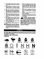


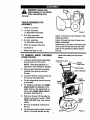
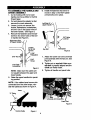
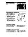
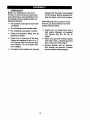


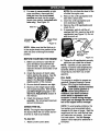
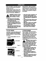


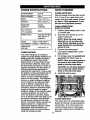
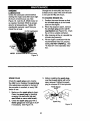


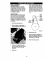
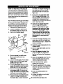

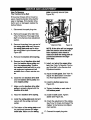
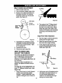

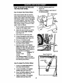
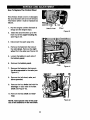

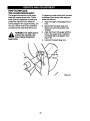
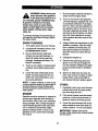
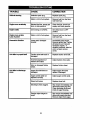

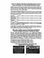
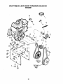


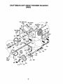


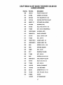
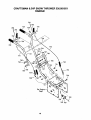

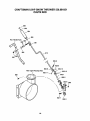

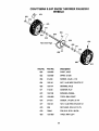
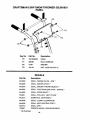

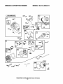
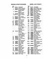
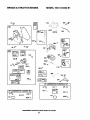

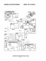
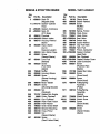
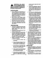

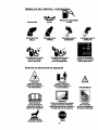

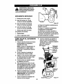
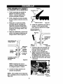
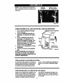

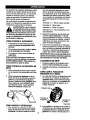
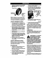
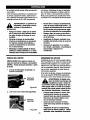
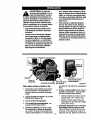
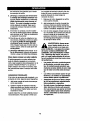
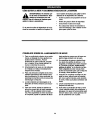
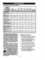

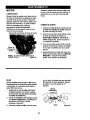

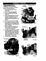
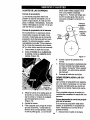


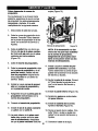
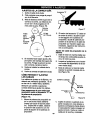
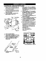
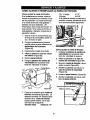
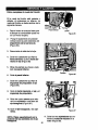

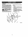


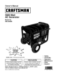
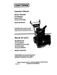
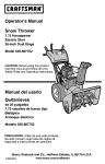
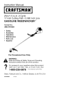
![CRRFTSMRN °] - at snowblowerguide.com](http://vs1.manualzilla.com/store/data/006202620_1-711fb90bb2c79d693479b4ac54c29ad0-150x150.png)