1
perator's
PROFESSIONAL
33-inch
Wide Cut Mower
Model No. 247.889980
For answers to your questions
call 1-800-4MY=HOME.
about
this product,
,
CAUTION: Before using this
product, read this manual and
follow all safety rules and operating
instructions.
Sears,
Roebuck
and Co., Hoffman
Visit our website:
Estates,
SAFETY
ASSEMBLY
OPERATION
MAINTENANCE
PARTS LIST
ESPANOL R 48
IL 60179, U.S.A.
www.sears.com/craftsman
FormNo.769-04684A
(December21,2009)
Warranty Statement ..........................................................
Safety Instructions ............................................................
Slope Guide .......................................................................
Safety Labels ....................................................................
Assembly ...........................................................................
Know your Lawn Mower ..................................................
Operation ........................................................................
CRAFTSMAN
2
3
5
6
8
11
14
Service and Maintenance ..............................................
16
Off-Season Storage ........................................................
26
Accessories and Attachments ........................................ 26
Troubleshooting ..............................................................
27
Parts List .........................................................................
28
Espa_ol ............................................................................
48
Service Numbers .............................................
Back Cover
PROFESSIONAL
FULL WARRANTY
Whenoperatedand maintainedaccordingto all suppliedinstructions,if this CraftsmanProfessionalproductfails due to a defectin materialor
workmanshipwithintwo years from thedateor purchase,call 1-800-4-MY-HOME®
to arrangefor free repair(or replacementif repairproves
impossible).
This warrantyappliesfor onlyone yearfromthe dateof purchaseif this productis everusedfor commercialor rentalpurposes.
This warrantycoversONLYdefectsin materialand workmanship.Searswill NOT payfor:
•
Expendableitemsthat becomewornduringnormaluse, includingbutnot limitedto blades,spark plugs,air cleaners,belts,and oil filters.
Standardmaintenanceservicing,oil changes,or tune-ups.
Tire replacementor repaircausedby puncturesfrom outsideobjects,such as nails,thorns,stumps,or glass.
Tireor wheelreplacementor repairresultingfrom normalwear,accident,or improperoperationor maintenance.
Repairsnecessarybecauseof operatorabuse, includingbutnot limitedto damagecausedby impactingobjectsthat bendthe frameor
crankshaft,or over-speedingtheengine.
Repairsnecessarybecauseof operatornegligence,includingbut not limitedto, electricaland mechanicaldamagecausedby improper
storage,failureto usethe propergradeand amountof engineoil, failureto keepthe deck clearof flammabledebris, or failureto maintainthe
equipmentaccordingto the instructionscontainedin the operator'smanual.
Engine(fuelsystem)cleaningor repairscausedbyfuel determinedto be contaminatedor oxidized(stale).In general,fuel shouldbe used
within30 daysof its purchasedate.
Normaldeteriorationand wearof the exteriorfinishes,or productlabel replacement.
Thiswarrantyappliesonly whilethis productis withinthe UnitedStates.
This warrantygivesyou specificlegal rights,and you mayalso haveotherrightswhich vary from stateto state.
Sears, Roebuck and Co., Noffman Estates, IL 60179
Gross HP:
12.5
EngineOil:
Fuel:
SAE 30
UnleadedGasoline
SparkPlug:
Champion®RC12YC
Engine:
Briggs& StrattonPowerBuiltTM
© SearsBrands,LLC
Model Number
Serial Number
Dateof Purchase
Recordthe modelnumber,serialnumber,
and dateof purchaseabove.
2
__IL
which,ifnot followed,couldendangerthe personal
his symbolpointsout
important
safetyinstructions
safetyand/or
propertyof
yourselfand
others.Read
and followall instructions
in this manualbefore
attemptingto operatethis machine.Failureto complywith these
instructions
may resultin personalinjury.Whenyou seethis symbol,
HEEDITS WARNING!
Your Responsibility: Restrictthe useof this powermachineto
personswhoread,understand,and followthe warningsand instructions inthis manualand on the machine.
This machinewas builtto be operatedaccordingto the rulesfor
safe operationin this manual.As with anytype of powerequipment,
carelessnessor error on the partof the operatorcan resultin serious
injury.This machineis capableof amputatinghandsand feet and
throwingobjects.Failureto observethefollowingsafetyinstructions
could resultin seriousinjury or death.
__ate
of Californiato I
causecancer and birthdefectsor otherreproductiveharm.
CHILDREN
,,
Tragicaccidentscan occur if operatoris not alert to presenceof children.Children areoften attractedto mowerandmowingactivity.Theydo not understand
the dangers.Neverassumethat childrenwill remainwhereyou lastsawthem.
,,
Keepchildren out of the mowingarea and underwatchfulcare of a
responsibleadult otherthanthe operator.
,,
Be alert andturn moweroff if a child entersthe area.
To helpavoid bladecontactor a thrownobject injury,stay in operator
zone behindhandlesand keepchildren,bystanders,helpers,and pets at
least75 feet from mowerwhile it is inoperation.Stopmachineif anyone
entersarea.
,,
Alwayswearsafetyglassesor safetygoggles duringoperationand while
performingan adjustmentor repairto protectyoureyes. Thrownobjects
which ricochetcan causeserious injury to the eyes.
,,
Beforeandwhile movingbackwards,look behindanddown for small
children.
,,
,,
Useextremecare when approachingblind corners,doorways,shrubs,
trees, or otherobjectsthat may obscureyourvisionof a childwho may
run into the mower.
,,
,,
Keepchildren awayfrom hot or runningengines.They can suffer burns
from a hot muffler.
,,
,,
Neverallow childrenunder 14yearsold to operatea power mower.
Children14years old and overshouldread and understandoperation
instructionsand safetyrulesin this manualand shouldbe trainedand
supervisedbya parent.
Wear sturdy,rough-soledwork shoesandclose-fittingslacksandshirts.
Shirts and pantsthat coverthe armsand legs andsteel-toedshoes
are recommended.Neveroperatethis machinein barefeet, sandals,
slipperyor light weight (e.g.canvas) shoes.
Donot put handsor feetnear rotating partsor undercutting deck.
Contactwith bladecan amputatehandsandfeet.
A missingor damageddischargecover can causebladecontact or
thrown objectinjuries.
Manyinjuriesoccur as a resultof the mower beingpulledoverthe foot
duringa fall causedby slippingor tripping.Do not hold on to the mowerif
you are falling; releasethe handleimmediately.
Neverpull the mowerbacktoward you whileyou are walking.If you must
backthe mowerawayfrom a wall or obstructionfirst look down and
behindto avoid trippingandthenfollow thesesteps:
a. Step backfrom mowerto fully extendyourarms.
b.Be sureyou are wellbalancedwithsure footing.
c. Pull backslowly,no morethan half waytowardsyou.
d. Repeatthese steps as needed.
Donot operatethe mowerwhile underthe influenceof alcoholor drugs.
GENERAL
,,
,,
,,
,,
,,
,,
OPERATION
Readthis operator'smanualcarefullyin its entirety beforeattempting
to assemblethis machine.Read,understand,andfollow all instructions
on the machineand inthe manual(s)beforeoperation.Be completely
familiarwiththe controlsand the properuse of this machinebefore
operatingit. Keepthis manualin a safe place forfuture andregular
referenceand for orderingreplacementparts.
This machineis a precision pieceof powerequipment,not a plaything.
Therefore,exerciseextremecautionat all times.Your unit has been
designedto performonejob: to mowgrass. Do not use it for anyother
purpose.
Neverallow childrenunder 14yearsold to operatethis machine.
Children14years old and overshouldread and understandthe instructions inthis manualand shouldbe trainedandsupervisedby a parent.
Onlyresponsibleindividualswho arefamiliar withthese rulesof safe
operationshouldbe allowedto usethis machine.
Thoroughlyinspectthe area wherethe equipmentis to be used.Remove
all stones,sticks,wire, bones, toysand otherforeignobjectswhichcould
be trippedoveror picked up and thrown bythe blade.Thrownobjects
can causeseriouspersonalinjury.Plan yourmowingpatternto avoid
dischargeof materialtoward roads,sidewalks,bystandersandthe like.
Also,avoid dischargingmaterialagainst a wall or obstructionwhich may
causedischargedmaterialto ricochetback towardthe operator.
,,
,,
Donot engagethe self-propelledmechanismon units so equippedwhile
startingengine.
,,
The blade control handleis a safety device.Neverattemptto bypassits
operation.Doingso makesthe safetydevice inoperativeand may result
inpersonalinjury through contactwiththe rotatingblade.The blade
control handle mustoperateeasily inboth directionsand automatically
returnto the disengagedpositionwhen released.
Neveroperatethe mowerin wet grass.Alwaysbe sureof yourfooting. A
slip andfall can causeseriouspersonalinjury.If you feel you are losing
yourfooting, releasethe bladecontrol handleimmediatelyandthe blade
will stop rotatingwithinthreeseconds.
,,
,,
,,
3
Mowonly in daylightor good artificial light. Walk, neverrun.
Stopthe bladewhen crossing graveldrives,walks or roads.
•
If the equipmentshould startto vibrateabnormally,stop the engine and
check immediatelyfor the cause.Vibrationis generallya warningof
trouble.
•
Shutthe engineoff andwait untilthe bladecomesto a completestop
beforeremovingthe grass catcheror uncloggingthe chute.
The cuttingblade continuesto rotatefor a fewseconds afterthe engine
is shut off. Neverplace any part of the bodyinthe bladearea untilyou
aresure the bladehas stoppedrotating.
•
•
•
•
•
•
•
Neveroperatemowerwithoutproper trailshield,dischargecover,grass
catcher,bladecontrol handle,or othersafety protectivedevices in place
andworking.Neveroperate mowerwithdamagedsafetydevices.Failure
to do so can resultin personalinjury.
Mufflerandengine becomehot and can causea burn.Do not touch.
Only use partsand accessoriesmadefor this machineby manufacturer.
Failureto do so can result in personalinjury. For recommendedaccessories,call 1-800-659-5917.
If situationsoccurwhich are not coveredinthis manual,use careand
goodjudgment. ContactyourSears ServiceCenterfor assistance.
SLOPE
•
•
•
If gasolineis spilled,wipe it off the engineand equipment.Moveunit
to another area.Wait 5 minutesbeforestarting engine.
•
Neverstorethe machineor fuel container nearan openflame, spark
or pilot light ason a waterheater,spaceheater,furnace,clothesdryer,
or othergas appliances.
•
To reducefire hazard,keepmowerfree of grass, leaves,or other
debris build-up.Clean up oil or fuel spillage andremoveany fuel
soakeddebris.
•
Allow a mowerto cool at least 5 minutesbeforestoring.
General Service:
•
•
OPERATION
Slopesare a major factorrelatedto slip andfall accidentswhichcan resultin
severeinjury.Operationon slopesrequiresextracaution.Ifyou feel uneasyon
a slope,do not mow it.For yoursafety,usethe slope guideincludedas part of
thismanualto measureslopes beforeoperatingthis unit on a slopedor hilly
area.If the slope is greaterthan 15 degrees,do not mowit.
Do:
•
Mow acrossthe face of slopes; never up anddown. Exerciseextreme
cautionwhen changingdirectionon slopes.
•
Watchfor holes,ruts,rocks, hiddenobjects,or bumpswhich can cause
youto slip or trip.Tall grasscan hide obstacles.
•
Alwaysbe sureof your footing.A slip andfall can causeseriouspersonal
injury.If you feel you are losingyour balance,releasethe bladecontrol
handle immediately,andthe bladewill stop rotatingwithin3 seconds.
Do Not:
•
Neverremovegas cap or addfuel while engineis hot or running.
Allow engineto cool at least two minutesbeforerefueling.
Neveroverfill fuel tank.Fill tank to no morethan V2inch belowbottom
of filler neckto provideforfuel expansion.
Replacegasolinecap andtighten securely.
•
•
•
•
•
Do not mow neardrop-offs, ditchesor embankments,whereyou could
lose yourfooting or balance.
Do not mow slopesgreaterthan 15degrees asshown on the
slope gauge.
Do not mow on wetgrass. Unstablefooting could causeslipping.
•
SERVICE
•
Safe Handling Of Gasoline:
•
Toavoid personalinjury or propertydamage useextreme care in
handlinggasoline. Gasolineis extremelyflammableandthe vapors are
explosive.Serious personalinjury can occurwhen gasolineis spilledon
yourselfor yourclotheswhichcan ignite.
•
Washyourskin andchangeclothesimmediately.
•
Useonly an approvedgasolinecontainer.
•
Neverfill containersinsidea vehicle or on a truckor trailer bedwith a
plastic liner.Alwaysplace containerson the ground awayfrom your
vehiclebeforefilling.
•
Removegas-poweredequipmentfrom the truck or trailer and refuel it on
the ground. If this is not possible,then refuel such equipmenton a trailer
witha portablecontainer,ratherthan from a gasolinedispensernozzle.
•
Keepthe nozzlein contact withthe rim of the fuel tank or container
openingat all times until fueling is complete.Donot usea nozzle
lock-opendevice.
•
Extinguishall cigarettes,cigars, pipesand othersources
of ignition.
•
Neverfuel machineindoorsbecauseflammablevapors will accumulate
inthe area.
•
•
•
4
Neverrun an engine indoorsor in a poorlyventilatedarea.Engine
exhaustcontainscarbon monoxide,an odorlessand deadlygas.
Beforecleaning, repairing,or inspecting,makecertainthe bladeand
all movingparts havestopped.Disconnectthe sparkplug wire and
ground againstthe engine to preventunintendedstarting.
Checkthe bladeand engine mountingboltsat frequentintervalsfor
propertightness.Also, visuallyinspectbladefor damage(e.g.,bent,
cracked,worn) Replacebladewith the original equipmentmanufacture's(O.E.M.)bladeonly, listedin this manual.Use of parts whichdo
not meetthe originalequipmentspecificationsmay lead to improper
performanceandcompromisesafety!
Mowerbladesare sharpand can cut. Wrap the bladeor weargloves,
and use extra cautionwhen servicingthem.
Keepall nuts, bolts, andscrewstight to be surethe equipmentis in
safe workingcondition.
Nevertamperwith safetydevices.Checktheir proper
operationregularly.
After strikinga foreignobject, stop the engine,disconnectthe spark
plugwire and groundagainstthe engine.Thoroughlyinspectthe
mowerfor any damage. Repairthe damagebeforestartingand
operatingthe mower.
Neverattemptto makea wheelor cutting heightadjustmentwhilethe
engine is running.
Grasscatchercomponents,dischargecover,andtrailshieldare
subjectto wear anddamagewhichcould exposemovingparts or
allowobjectsto be thrown.For safetyprotection,frequentlycheck
componentsand replaceimmediatelywithoriginalequipment
manufacturer's(O.E.M.)parts only, listedin this manual.Use of parts
which do not meet the original equipmentspecificationsmay leadto
improperperformanceand compromisesafety!
Donot changethe engine governorsetting or overspeedthe engine.
The governorcontrolsthe maximumsafe operatingspeed of the
engine.
Maintainor replacesafetylabels, as necessary.
Observeproper disposallawsand regulations.Improperdisposalof
fluids and materialscan harmthe environment.
Use this pageas a guide to determineslopeswhereyoumay not operatesafely.Do not operate the lawnmoweron such slopes.
!
l
I
I
!
!
!
This symbolpoints outimportantsafety instructions
which,ifnot followed,could endangerthe personalsafetyand/or propertyof yourselfand
others.Readand follow all instructions
inthis manualbeforeattemptingto operatethis machine.Failureto complywith these instructions
may
result inpersonalinjury.Whenyou seethis symbol,HEEDITS WARNING!
WARNING
This symbol points out important safety instructions
which, if not followed, could endanger the personal
safety and/or property of yourself and others. Read and
follow all instructions in this manual before attempting
to operate this machine. Failureto comply with these
instructions may result in personal injury. When you see
this symbol HEED ITS WARNING!
Your Responsibility
Restrict the use of this power machine to persons who
read, understand, and follow the warnings and instructions in this manual and on the machine.
6
Thispageleftintentionally
blank.
7
IMPORTANT:This unitis shippedwith oil in the engine.After
assembly,see page 12for fueland oil details.
Attaching
The positivecable (heavyred wire)is securedto the positivebattery
terminal(+)with a hex boltand hex nutat thefactory.
The negativecable(heavy blackwire) maybe securedto the negative
batteryterminalat the factory.If it hasn'tbeen attached,proceedas
follows:
Disconnectthe spark plugwire and groundit againstthe engineto
preventunintendedstarting.
PARTS IN CARTON
Removethe carriagebolt and hexnut from the positivecable
(heavy red wire).
Thefollowingitemsare packagedin a bag:
Operator'sManual,Oil drain hose,Waterhosecoupler,EngineManual
TOOLS
NEEDED
.
FOR ASSEMBLY
A set of adjustablewrenchesand tiregauge
MOWER
SET-UP
Shipping
Brace Removal
Cables
NOTE: The positivebatteryterminalis markedPos. (+).The negative
batteryterminalis markedNeg. (-).
IMPORTANT:Referenceto rightor left side of the moweris observed
fromthe operatingposition.
LOOSE
the Battery
Removethe red plasticcover,if present,from the positivebattery
terminaland attachthe positivecableto the positivebattery
terminal(+)with the bolt and hexnut. See Figure2.
f
Makesurethe lawnmower'sengineis off. Removetheignitionkey
beforeremovingthe shippingbrace.
1.
Locatethe shippingbrace,if present,foundon the rightside of
thecuttingdeck. See Figure1.
Figure2
Figure1
.
3.
Removethe carriagebolt and hexnut from the negativecable
(heavy blackwirel
4.
Removethe black plasticcover,if present,from the negativebattery terminaland attachthe negativecableto the negativebattery
terminal(-) with the boltand hexnut. See Figure2.
5.
Makecertainthe hold-downrod is in positionoverthe battery,
securingit in placeand makecertain that the red rubberbootcovers the positivebatteryterminalto help protectit fromcorrosion.
NOTE: If the batteryis putinto serviceafter the dateshown
on top/sided battery,chargethe batteryas instructedin the
Maintenancesectionof this manualprior to operatingthe mower.
Whileholdingthe dischargechutewith your left hand,removethe
shippingbracewith yourright handby graspingit betweenyour
thumband indexfingerand rotatingit clockwise.
Theshippingbraceis usedfor packagingpurposesonly. Remove
and discardthe shippingbracebeforeoperatingyourlawnmower.
Themowingdeck is capableof throwingobjects.Failureto operate
I the mowerwithoutthedischargecoverin the properoperatingposiltion could resultin seriouspersonalinjuryand/or propertydamage.
8
Unfolding
1.
the Handle
Attaching
1.
Removethestar knobsand carriagescrewsfrom thelower
handle.See Figure3.
the Shift
Lever
Removethe screwandthe lock nutthat securesthe shift leverto
the shift leverplate.See Figure5.
f
Figure3
.
Figure5
Pivotthe upper handleintooperatingposition.Be careful notto
crimpcables.See Figure4.
2.
Removethe remainingscrewand nut from the lowershiftlever
plate.See Figure5.
3.
Positionthe uppershift leverintoa verticalpositionaligningthe
holesin the leverwith the holesin the shift plate.See Figure6.
f
Figure4
3.
Reinstallthe carriagescrewsand knobs removedearlier.
4.
Tightenthe upperand lowerstar knobsand carriagescrewsto
securethe upperhandleto the lowerhandle,See Figure4.
5.
..t'
Figure6
Securethe leverto the plateusingthe two screwsand two nuts
removedearlier.See Figure6.
Thehandle heightcan be adjustedto anyof three positions.
For instructions,referto HandleHeightin the Maintenanceand
Adjustmentssectionof this manual.
9
Checking
Tire Pressure
Maximumtire pressureunderany circumstancesis30 psi. Equaltire
pressureshouldbe maintainedat all times.
The reartires on your unitmay be over-inflatedfor shippingpurposes.
Reducethe tire pressurebeforeoperatingthe mower.Recommended
operatingtire pressureis approximately20 p.s.i.Checkthe sidewallof
tirefor maximump.s.i.
Gas and Oil
Thefuel tank hasa capacityof two gallons. Removethe fuelcap by
turningit counterclockwise.Useonly clean,fresh (no morethan30
daysold), unleadedgasoline.Fillthe tank no higherthanfour inches
belowthetop of the filler neckto allow spaceforfuel expansion.
Useextremecarewhenhandlinggasoline.Gasolineis extremely
flammableand the vaporsare explosive. Neverfuel the machine
indoorsor whilethe engineis hot or running.Extinguishcigarettes,
cigars,pipes andother sourcesof ignition.
NOTE:Your lawnmoweris shippedwith oil in the engine.However,
you MUSTchecktheoil levelbeforeoperating.Referto the Service
and MaintenanceSectionfor CheckOil instructions.
Alwayschecktheengineoil levelbeforeeachuse. Add oil as necessary.Failureto do so may resultin seriousdamageto yourengine.
10
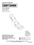
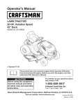
Fuel Tank Ca
Deck Height
Lever
===='_
ignition Switch
Systems indicator Monitor
Drive Control
Gear Shift Lever
Figure7
f
Spark
--
oil
Dipstick
Plug
Referto the Maintenancesectionfor instructions
on spark plug
replacement.
Air
Cleaner
Handle
Oil Cap/Dipstick
Referto the Maintenancesectionfor instructions
on checkingthe oil.
MOWER
CONTROLS
Referto Figure7 for locationsof the mowercontrols.
Throttle/Choke
Control
NOTE:Whenoperatingthe mowerwith the
cuttingdeck engaged,be certain that the
throttle/chokecontrolis in the fast position.
_,,
J
CONTROLS
fast positionfor best mowerperformance.
Referto Figure8 for locationsof the enginecontrols.
CHOKE:Use whenstartinga cold engine.
Oil Drain Valve
FAST:Useduringmoweroperation.
Usetheoil drain valveto drain oil from the engine.Referto the
Maintenancesectionfor instructions.
Air Cleaner
Fast
THE throttle/chokecontrolis usedto adjust
engine speeds,to activatethe enginechoke
and to stopthe engine.Alwaysrun engine
with the throttle/ chokecontrol leverinthe
Figure8
ENGINE
Choke==_
SLOW: Usewhenidling engine.
Slow ==_
STOP:Stopsthe engine.
Handle
Theair cleanerhandleis usedto gain accessto the air cleaner.The air
cleanercartridgecan be removedand cleanedor replaced.Referto
the Maintenancesectionfor details.
11
REFERto StartingThe Enginein the
Operationsectionof this manualfor detailed
startinginstructions.
Stop
Deck
Height
Drive Control
Lever
Use this leverto adjustthe mowingdeck'scuttingheight.To use,move
the leverto the left, then placetheleverin the notchbest suitedfor
yourapplication.
ignition
The drivecontrolis usedto engageand
disengagedriveto the wheels.Toengage
this control,squeezethe drivecontrol
againstthe handlebargrip.To stopthe drive,
releasethedrive control.
Switch
@
Neverleavea runningmachineunattended.Alwaysdisengage
blades,stopengine and removekey to preventunintendedstarting.
The four-position
electric-start
ignition
f
switch
is used to start and stop the engine on
models, To start the engine,
switch
and turn clockwise
insert the key into the
to the START (;_
Alwaysreleasethedrivecontrol beforechangingspeeds.Failureto
do so may resultin seriousdamageto yourtransmission.
position,
Release key into the RUN _
position<,:_once the engine has started,
Move the key into the RUN/LIGHT _)_ position to run the mower
with the headlight
See Figure 9,
on, Turn the key
to'STOP
0
Blade
to stop the engine,
Locatedon the right-handhandle,the blade
control is usedto engagethe mowingdeck.
Tooperate,pressand holdthe leveragainst
the handlebargrip.To stopthe blades,
releasethe bladecontrol.
Run/Light
Stop
Position
_1
Control
,ik
Run
@
Neverattemptto start theenginewith the bladecontrolengaged.
Figure9
Alwaysreleasethe bladecontrol whenstartingthe engine.Failureto
do somay result in prematurewearto yourengine'selectricstarter.
Nevermovethe key intothe Start positionwhile the engineis running;
doingso may causedamageto the engine'sstarter.
12
GEAR SHIFT
LEVER
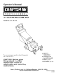
SYSTEMS INDICATOR MONITOR/HOUR
METER
BATTERY
jJ
j
Use this leverto selectanyof four forwardgroundspeeds,neutral,or
reverse.
j/
42.0
Forward
///
Fourforwardspeedsare available.Positionone (1) is the slowestand
positionfour(4) is thefastest.
HOURS 1/10 \\\
jf
Reverse
Toselectreverse,putthe leverin the Reverse(R) position.
Figure10
LCD
Lookbehindthe mowerbeforeand during reverseoperation.Stopthe
mowerbladesbeforeoperatingin reverse.
Whenthe ignitionkey is rotatedout of the STOPpositionbut not
intothe STARTposition,the systemsindicatormonitordisplaysthe
battery'soutput,in volts, on its LCD for approximatelyfive seconds,
after which it displaysan hourglass and the hoursof moweroperation.
Oncethe engineis started,the monitorcontinuallydisplaysan hour
glass and the hoursof moweroperationon its LCD.See Figure10.
Neutral
Placethe leverin neutral(N) beforestartingthe mowerand whenthe
moweris not in use. In addition,the mowercan be manuallypushed
or pulled by placingthe gear shiftleverinto N (neutral)positionand
pressingthe drivecontrolagainstthe handlebargrip.
NOTE:Hoursof moweroperationare recordedanytime the ignition
keyis rotatedout of the STOP_i _ position,regardlessof whetherthe
engine is started.
Alwaysreleasethe drivecontrolbeforechangingspeeds.Failureto
do so may resultin seriousdamageto yourtransmission.
The IndicatorMonitorwill also remindthe operatorof maintenance
intervalsfor changingthe engineoil. The LCDwill alternatelyflash the
recordedhours,"CHG"and "OIL' forfive minutes,after every50 hours
of recordedoperationelapse.The maintenanceintervallastsfor two
hours(from 50-52, 100-102,150-152,etc.). The LeD willalso flash
as describedabovefor five minuteseverytime the mower'sengine
hasbeen startedduring this maintenanceinterval.Beforethe interval
expires,changetheengine oil as instructedin the Maintenancesection
of this Operator'sManual.
Battery
It is normalfor the Batterylightto illuminatewhilethe engineis
crankingduringstart-up,but if it illuminatesduring operation,whilethe
engine is running,the batteryis in needof a chargeor the engine's
chargingsystemis not generatingsufficientamperage.Chargethe
batteryas instructedin the Servicesectionof this manualor havethe
chargingsystemcheckedby Searsor anotherqualifiedservicedealer.
13
STARTING
THE ENGINE
Totravel in REVERSE,
Referto the Serviceand Maintenancesectionof this manualfor
a.
Checkthat the area behindis clear.
Gasolineand Oil fill-up instructions.
b.
Placethe gear shift leverin Reverse(R).
1.
Disengageall controlson the mower.
c.
2.
Movethe gear shiftleverinto the neutral(N) position.
Slowlysqueezethe DriveControlagainsttheleft handlegrip
and themowerwill move.Releaseitand drivemotionwillstop.
3.
Insertthe key intothe ignitionswitch.
4.
If startinga cold engine,placethe throttle/chokecontrolall the
wayforward,intothe CHOKE1'_,1
position.If restartinga warm
engine,placethe throttle/chokecontrolintothe Fast'_
position.
5.
Turnthe ignitionkey clockwiseto the START___ position.After
theengine starts,releasethe key.It will returnto the RUN(_q)
position.
6.
Movethe key to the RUN/LIGHT_-:i'_i:
positionto operatethe
mowerusingthe headlight.
DoNOT attemptto changethe directionof travel whenthe moweris
in motion.Alwaysreleasethedrivecontrol and bringthe mowerto a
completestop beforerepositioningthegear shift leverfrom a forward
gear into Reverse.Failuretodo so may resultin seriousdamageto
rourtransmission.
Donot leavethe operator'spositionwithoutfirst releasingthe Blade
Control.If leavingthe mowerunattended,also turnthe engineoff and
removethe ignitionkey.
ENGAGING
Do NOThold the key in the STARTpositionfor longerthan five
secondsat a time.Doingso maycause damageto yourengine's
electricstarter.
THE BLADES
Tohelp avoidblade contactor a thrownobject injury,keepbystand7.
Movethe throttle/chokecontrolintothe FAST_
position.
lets, helpers,childrenand pets at least75 feet from the machinewhile
lit is in operation.Stopmachineif anyoneentersthe area.
NOTE: Neverleavethe throttle/chokecontrol in the CHOKEI_,1
positionwhileoperatingthemower.Doingso will resultin a "rich"fuel
mixtureand cause theengineto run poorly.
Stopping
1.
Movethethrottle/chokecontrolto the FAST_
2.
Slowly squeezethe BladeControlagainstthe righthandlegrip
and the bladeswill engage.Releaseit and the bladeswill stop.
the Engine
OPERATING
1.
If the bladesare engaged,releasethe BladeControl.
2.
Movethe throttle/chokecontrolintothe STOPI_ position.
3.
Turnthe ignitionkey counterclockwiseto the STOP0
4.
Removethe keyfrom the ignitionswitchto preventunintended
starting.
Donot mowon inclineswith a slopein excessof 15degrees(a rise
of approximately2-1/2feet every 10feet).The mowercouldoverturn
and cause seriousinjury.
position.
THE DRIVE
Avoidsuddenstarts,excessivespeedand suddenstops.
•
Mowacrosstheface of slopes;neverup and down.
•
Exerciseextremecautionwhenchangingdirectionon slopes.
•
Watchfor holes,ruts, rocks,hiddenobjects,or bumpswhich can
causeyou to slip or trip. Tallgrass can hideobstacles.
•
Alwaysbe sureof yourfooting.A slipand fall can causeserious
personalinjury.If you feelyou are losingyourbalance,release
the blade controlhandleimmediatelyand the blade willstop
rotatingwithinthree (3) seconds.
•
Donot mow neardrop-offs,ditchesor embankments,you could
lose yourfootingor balance.
•
Donot mow slopesgreaterthan 15degreesas shownon the
slopegauge.
•
Donot mowon wet grass.Unstablefootingcouldcauseslipping.
Start the engineas instructedearlierin this sectionand movethe
throttle/chokecontrolintothe FAST'_ position.
Totravel FORWARD:
a.
b.
ON SLOPES
Referto the SLOPEGUIDEon page5 to help determineslopeswhere
you mayoperatethemowersafely.
e beforerestartinc
ENGAGING
position.
Placethegear shift leverin anyof the fourforwardground
speeds.Selecta speedappropriatefor the conditionsand a
paceyou'recomfortablewith.
Slowlysqueezethe DriveControlagainstthe left handlegrip
andthe mowerwillmove.Releaseitanddrivemotionwillstop.
14
USING THE DECK HEIGHT LEVER
INSTALLING/REMOVING
Toraiseor lowerthecuttingdeck, movethe deck heightleverto the
left,then placeit in the notch best suitedforyour application.
MULCH
BAFFLE
Beforeinstallingor removingthe mulchbaffle,disengageblades,sto
the engineand removekeyto preventunintendedstarting.
MOWING
Thefollowinginformationwill be helpfulwhenoperatingyour mower.
Stoptheengineand wait for all parts to stop moving.
Installing
Planyour mowingpatternto avoiddischargeof materialstoward
roads,sidewalks,bystanders.Also, avoiddischargingmaterial
againsta wall or obstructionwhich maycause dischargedmaterialto
ricochetback towardtheoperator.
•
Do not mowat fastground speeds,especiallyif a mulch kit or
grasscollectoris installed.
•
Do notcut thegrass too short.Shortgrass is proneto weed
growthand yellowsquicklyin dry weather.
•
Alwaysoperatethe mowerwith thethrottle/chokecontrol in the
FAST_ positionwhile mowing.
•
For best resultsit is recommendedthat the firsttwo laps be cut
with the dischargethrowntowardsthe center.Afterthe first two
laps, reversethe directiontothrow the dischargeto the outside
for the balanceof cutting.This will givea betterappearanceto the
lawn.
the Mulch Baffle
1.
Insertthe right-sidetab (A) of the baffleinto the bracketon the
deck. See Figure11.
2.
Insertthe mulchbaffleinto thedischargeopening(B). See
Figure11.
3.
Onceit's positionedin thedeck opening,pushthe baffle towards
the rear of the mower(C) to secureit in place.
See Figure11.
Do NOTattemptto mow heavybrushand weedsor extremelytall
grass.Yourmoweris designedto mowlawns,NOTclear brush.
Keepthe bladessharpand replacethe bladeswhenworn.
After strikinga foreignobject,stop the engine,disconnectthe spark
plug wireand groundagainsttheengine.Thoroughlyinspectthe
mowerfor any damage.AlwaysInspectthe bladetiming belt as
instructedin the Maintenancesectionof this manual.Repairthe
damagebeforestartingand operatingthe mower.
Figure11
Removing
MULCHING
TheCraftsmanPro WideCut moweris equippedwith a mulch kit (supplied with the mower),which uses specialbladesto recirculategrass
clippingsrepeatedlybeneaththe cuttingdeck.The ultra-fineclippings
are thenforced backinto the lawnwherethey act asa naturalfertilizer.
Observethe followingpointsfor the best resultswhenmulching.
•
Neverattemptto mulchif the lawnis damp.Wet grasstends
to stick to the undersideof thecuttingdeck preventingproper
mulchingof the clippings.
Do NOTattemptto mulch morethan1/3the total heightof the
grass.Doingsowill cause theclippingsto clump up beneaththe
deck and not be mulchedeffectively.
•
Maintaina slow groundspeedto allowthe grassclippingsmore
time to effectivelybe mulched.
•
Alwayskeepthe throttlecontrol leverin the FAST,_ position
whilemowing.Failingto keepthe engineat full throttleplaces
strainon the mower'sengineand does notallowthe bladesto
properlymulchthe grass clippings.
15
the Mulch
Baffle
Slidethe baffleto the right(towardthe front of the mower)to disengage the slot fromthe mowerdeck and then prythe left-sideof the
baffleoutward.
MAINTENANCE
.
Beforeperformingany maintenanceor repairs,disengageblades,
stopengineand removekey to preventunintendedstarting.
GENERAL
•
RECOMMENDATIONS
Togain access to theoil drain valveon the engine,pivotthe right
handle bracetube forward.
a.
Removethe upper starknob and carriagescrewon the right
side of the handle,Figure12.
b.
Pivotthe bracetube towardsthefront of the mowerto allow
roomto connectthe oil drain hoseto the oil drainvalve,
Figure12.
Alwaysobservesafetyruleswhenperformingany type of
maintenanceon the mower.
Thewarrantyon this lawnmowerdoesnot coveritemsthat have
been subjectedto operatorabuseor negligence.To receivefull
valuefromwarranty,operatormustmaintainthe lawnmoweras
instructed
in this manual.
•
Changingof engine-governedspeedwill voidenginewarranty.
•
All adjustmentsshouldbe checkedat least onceeach season.
•
Periodicallycheckall fastenersand makesuretheyare tight.
ENGINE
MAINTENANCE
Checking
the Engine
Oil
Checkoil levelbeforeeachuse. Stopengineand wait severalminutes
beforecheckingoil level.With engineon levelground,
theoil mustbe to FULLmark on dipstick.
1.
Removethe Oil Cap/Dipstickand wipewith a
cleancloth.
2.
Replaceand tighten Oil Cap/Dipstick.Remove
Oil Cap/Dipstickand checkoil level.Level
shouldbe at FULLmark.
Figure12
.
3.
If needed,add oil slowlyinto the engineoil fill. Recheckoil level.
Do notoverfill.
4.
ReinsertOil Cap/Dipstickand tighten.
Popoff the protectivecapon theend of theoil drainvalve to
exposethe drain port. See Figure13.
f
Oil Fill Cap/Dipstick
Do notoverfill.Overfillingwithoil may makethe enginehard to start,
or not to start. If overthe FULLmarkon the dipstick,drain oil levelto
FULLmark on dipstick.
Changing
the Engine
Oil
If the engine hasbeen recentlyrun,the engine,mufflerand surroundingmetal surfaceswill be hotand can causeburnsto the skin.
Exercisecautionto avoidburns.
\
\
Figure13
Theoil in theengine shouldbe changedafter thefirst two hoursof
operationand every25 hoursof operation.
4.
Removethe oil fill cap/dipstickfrom theoil fill tube, Figure13.
1.
5.
Pushtheoil drainhose(packedwiththismanual)ontotheoil drain
port. Routetheoppositeendd thehoseintoan appropriateoil collectioncontainerwithat leasta 2.5quartcapacity,tocollecttheusedoil.
6.
Releasethe valveby pressingthe two tabs inwardwhilepulling
the valveout. The oil will begin to drainout of the engine.
Runthe enginefor a few minutesto allowthe oil in the crankcase
to warmup. Warmoil will flow morefreelyand carry away moreof
theengine sedimentwhichmay havesettledat thebottomof the
crankcase.Use careto avoidburnsfrom hotoil.
16
7.
After theoil hasfinisheddraining,press thetwo tabs inwardand
pushthe oil drain valve backin to lock the valveclosed.Remove
the hose,and re-capthe end of the oil drain valveto keepdebris
from enteringthedrain port.
8.
Refillthe enginewith new motoroil until theoil levelon the
dipstickreadsFULL.Replacethe oil fill cap/dipstick.
9.
Pivotthe right handlebracetube back intoposition.Align the
middlehole in the bracetubewith the hole in the handle.Secure
with the star knoband carriagescrewremovedearlier.
Servicing
the Air Cleaner
If filters,or coversare notinstalledcorrectlyseriousinjury or death
could resultfrom backfire.Do not attemptto startthe enginewith
them removed.
Donot usepressurizedair or solventstoclean theair cleaner
cartridge.
Onlyuse high qualitydetergentoil ratedwith APIserviceclassification
SF or SG. Selectthe oil'sSAEviscosity gradeaccordingto your
expectedoperatingtemperature,Figure14.Althoughmulti-viscosity
oils (5W30,10W30etc.) improvestartingin cold weather,these multiviscosityoilswill resultin increasedoil consumptionwhenusedabove
32°RCheckyourengineoil levelmorefrequentlyto avoidpossible
enginedamagefrom runninglowon oil.
Cleanor replacethe air cleanerevery25 hoursof operation.
1.
Pullup on air cleanerhandle,Figure10,and pull backtowardsthe
engine.
Removethe air cleanercover,Figure16.
.
f
Air CleanerCover
Air Cleaner Cartridge
\
AirCleanerHandle
Oi!ViscositY Gila!!
_j
Figure14
Checking
the Spark Plug
Cleansparkplug and resettheelectrodegap to 0.030"at least oncea
season;replaceevery 100hoursof operation.
1.
2.
.
Cleanareaaroundthe spark plug base.Do notsandblastspark
plug.Sparkplug shouldbe cleanedby scrapingor wire brushing
and washingwith a commercialsolvent
-..
J
Figure16
Removeand inspectthe spark plug.Checkgap to makesureit is
set at .030".See Figure15.
3.
Replacethespark plug if electrodesare pitted,burned,or the
porcelainis cracked.Usea Champion®RC12YCspark plug.
Carefullyremoveair cleanercartridgeand pre-cleaner(if
equipped)fromthe blowerhousing.
4.
Cleanthe baseof the air cleanercartridgecarefullyto prevent
debrisfrom enteringthe engine.
5.
Placethe pre-cleaner,if equipped,and cartridge backintothe
blowerhousing.The cartridgemustbe placedsecurelyinto
position.
6.
Align tabs on cover with slotsin blowerhousingand replacethe
cover.
f
Electrode
1
_
Porcelain
"_
;
.030 inch(.76 rnm)gap
Figure15
17
BATTERY
1.
Batteryposts,terminals,and relatedaccessoriescontain leadand
leadcompounds,chemicalsknownto the State of Californiato cause
cancerand reproductiveharm.Washhandsafter handling.
Makecertain the mower'sdischargechute is directedAWAYfrom
your house,garage,parkedcars,etc.
The batteryis sealedand is maintenance-free.Acid levelscannotbe
checkedand fluidcan not be added.
•
Alwayskeepthe batterycablesand terminalscleanand freeof
corrosivebuild-up.
•
Aftercleaningthe batteryand terminals,applya lightcoat of
petroleumjelly or greaseto bothterminals.
Positionthe moweron a level,clearspot on yourlawn, near
enoughfor yourgarden hoseto reach.
.
Threadthe hosecoupler(packagedwith yourmower'sOperator's
Manual)ontothe end of yourgardenhose.
Attachthe hosecouplerto thewater porton the deck surface.
See Figure17.
If removingthe batteryforcleaning,disconnecttheNEGATIVE(Black)
wirefrom it'sterminalfirst,followedbythe POSITIVE(Red)wire.When
re-installingthe battery,alwaysconnectthe POSITIVE(Red)wireits
terminalfirst, followedby the NEGATIVE
(Black)wire.Be certainthat
thewiresare connectedto thecorrectterminals;reversingthem could
resultin seriousdamageto yourengine'salternatingsystem.
TIRE PRESSURE
Maximumtire pressureunderany circumstancesis 30 psi. Equaltire
pressureshouldbe maintainedat all times.
Periodicallycheckthe pressureon bothyour mower'sreartires.
Uneventire pressurewill causethe cuttingdeck to mow unevenly
and may resultin mowerto veeringto eitherthe left or rightduring
operation.Recommendedoperatingtire pressureis approximately20
p.s.i.Checkthe sidewallof tire for maximump.s.i.
CLEANING
Figure17
THE MOWER
Anyfuel or oil spilledon the machineshouldbe wipedoff promptly.Do
NOTallowdebristo accumulatearoundthe coolingfins of the engine,
thetransmission'scoolingfan or on any otherpartof the machine,
especiallythe beltsand pulleys.
Smart
Jet
Yourmower'sdeck isequippedwith a waterport on its surfaceas part
of its deck wash system.
Use the SmartJet to rinsegrass clippingsfrom thedeck'sunderside
and preventthe buildupof corrosivechemicals.Completethe following
stepsAFTEREACH MOWING:
Beforeusingthe deck washsystem,alwaysdisengagethe Blade
Control,stop engineand removekeyto preventunintendedstarting.
4.
Turnthe wateron.
5.
Start the engineand placethe throttleleverin the FAST,_
position.
6.
Whilein the operator'spositionbehindthemower,movethe
BladeControlintothe ON position.
7.
Remainin theoperator'spositionwith the cuttingdeck engaged
for a minimumof two minutes,allowingthe undersideof the
cuttingdeck to thoroughlyrinse.
8.
Movethe BladeControlintothe OFF position.
9.
Turnthe ignitionkey to the STOP(_ positionto turn themower's
engineoff.
10. Turnthe wateroff and detach the hosecouplerfrom thewater
port on yourdeck'ssurface.
After cleaningyourdeck with the SmartJet system,startthe mower's
engine,returnto the operator'spositionand engagethe blades.Keep
the cuttingdeck runningfora minimumof two minutes,allowingthe
undersideof the cuttingdeck to thoroughlydry.
LUBRICATION
Beforelubricating,repairing,or inspecting,alwaysdisengagePTO,
set parkingbrake,stopengine and removekey to preventunintended
starting.
18
Pivot Points & Linkage
BLADE
Lubricateall the pivotpointson thedrive systemand lift linkageat
least oncea seasonwith lightoil.
The cuttingdeck spindlesare drivenby a timing(cogged)belt,
assuringthat the deck bladesare alwaysperpendicularto eachother.
At least oncea season,or after strikingany foreignobject,checkthe
timing beltas follows:
Rear Wheels
The rearwheelsshouldbe removedfrom the axles oncea season.
Lubricatethe axles and rim hubswellwith an all-purposegrease
beforereinstallingthem.
Front
1.
TIMING
BELT
Removethe beltcover by removingthe threescrewsand washers
which secureit to the frame.See Figure20.
Wheels
Donot operatemowerwithoutthe belt coverinstalled.Failureto follow this instructioncould resultin personalinjuryor propertydamage.
Eachof the front wheelaxles and castersis equippedwith a grease
fitting. See Figure18.Lubricatewith a No.2 multi-purposegrease
appliedwith a greasegun after every50 hoursof moweroperation.
Figure20
Figure18
Deck
The top of eachspindlepulleyis markedwith an arrow. See
Figure21.Thearrowsshouldbe perpendicular(at a 90° angle)to
eachother.
Spindles
Greasefittings canbe foundon eachdeck spindle.See Figure19.
Lubricatewith 251HEPgreaseor an equivalentNo.2 multi-purpose
lithiumgrease.Usinga greasegun, applytwo strokes(minimum)or
sufficientgreaseto the spindleshaft.
\
Figure21
Figure19
19
3.
If the arrowson the surfaceof each spindlepulleyare not
perpendicular(ata 90°angle) to eachother,seeyour Searsor
otherqualifiedservicedealerto havethe timingbelt reset.
CUTTING
DECK REMOVAL
Beforeperformingany maintenanceor repairs,disengageblades,
stop engineand removekeyto preventunintendedstarting.
Do notoperatethe machinewithoutthe deck'stimingbelt properly
set. Failureto follow this instructioncould resultin personalinjuryor
propertydamage.
To removethe cuttingdeck,proceedas follows:
1.
ADJUSTMENTS
Donot operatemowerwithoutthe belt coverinstalled.Failureto follow this instructioncould resultin personalinjuryor propertydamage.
Shutthe engineoff and removethe ignitionkeybeforemaking
adjustments.
Handle
Removethe beltcover by removingthethree screwsand washers
which secureit to the frame.See Figure23.
Height
The upperhandleis securedto two support barsthat canbe adjusted
to raiseor lowerthe handle height.Adjustif necessaryas follows:
1.
Removethe upperstar knoband carriagescrewon the rightside
of the handleand the Idt side of the handle.
See Figure22.
J
Figure23
2.
Placethe deck heightleverin its highestposition.
3.
Positionwoodblocksatvariousplacesunderthedeck'sedge.
Thesewilltemporarilysupportthedeckin theprocessof removingit.
4.
Usethe deck heightleverto lowerthe deck, sothat it restson the
wood blocks.
Figure22
2.
Pivotthe handleforwardor rearwardto align one of the three
holeson each supportbar with the holeson the handle.
3.
Reinstallthe upperstar knoband carriagescrewon the rightside
of the handleand the Idt side of the handlewhena comfortable
heightis achieved.
2O
5.
Removethescrewand flangenut whichsecuresthe belt keeper
rod to the left sideof the mower'sframe.See Figure24.
13. Pullthe click pin outand unhookthe drivespringcablefrom the
idlerarm assembly.See Figure26.
j'
/
/
.................................
\
\
\
\
\
Figure24
.
.
Figure26
Removethebelt keeperrod and removethe deck beltfrom
aroundthe mower'senginepulley.
14. Gentlyslidethecuttingdeckto theright,outfrombeneaththe mower.
Lookingat the cuttingdeck fromthe left side,locate and carefully
removethe hairpinclips that securethe deck supportson the rear
left sideand front left side of thedeck. See Figure25.
Lift Arm
Figure25
8.
Repeatthe previousstepon the mower'srightside.
9.
Carefullyremovethe frontdeck supportsfromthe deck lift arms,
Figure25.
10. Carefullyunhookthe mower'slift assemblyfrom the rear deck
supports.
11. Use thedeck heightleverto raisethe lift assemblyto its highest
position.
12. Removethewoodenblocksfrom under thedeck and gently slide
the cuttingdeck towardthe rear of the machine.
21
To installthe cuttingdeck, followthe abovestepsin the oppositeorder
and mannerof removal.
CUTTING BLADES
.
Shutthe engineoff and removeignitionkey beforeremovingthe
cuttingblade(s)for sharpeningor replacement.Protectyour hands
usingheavygloveswhengraspingthe blade.
To properlysharpenthecutting blades,removeequalamounts
of metalfrom bothendsof the bladesalongthe cuttingedges,
parallelto the trailingedge,at a 250.to 300angle.Alwaysgrind
eachcuttingblade edge equallyto maintainproperblade balance.
See Figure28.
If the cuttingedgeof theblade has previouslybeen sharpened,or if
any metalseparationis present,replacethe bladeswith newones.
Periodicallyinspectthe bladeand/or spindlefor cracksor damage,
especiallyafter you've strucka foreignobject.Do not operatethe
machineuntil damagedcomponentsare replaced.
A poorlybalancedbladewill causeexcessivevibration,maydamage
to the mowerand/or resultin personalinjury.
Toremovetheblades, proceedas follows.
1.
Removethe deck from beneaththe mower,(referto CuttingDeck
Removalearlier in this section)thengently flip thedeck overto
exposeits underside.
2.
Placea blockof wood betweenthe centerdeck housingbaffle
and the cuttingbladeto act asa stabilizer.See Figure27.
Figure28
5.
NOTE: Whenreplacingtheblade,be sureto installthe blade with the
side of the blade marked"Bottom" (or with a partnumberstampedin
it) facingthe groundwhenthe moweris in the operatingposition.
J
Figure27
.
Testthe blade'sbalanceusinga blade balancer.Grindmetalfrom
the heavyend untilthe bladebalancesevenly.
Removethe hexflangenutthat securesthe bladeto the spindle
assembly.See Figure27.
Usea torquewrench totighten the bladespindlehexflangenut to
between70 Ibs-ftand 90 Ibs-ft.
The cuttingbladesmust be installedperpendicularto eachother.If
the bladescannotbe installedperpendicularto eachother,the blade
timing beltmust be reset.See yourSearsor otherqualifiedservice
dealerto havethe deck timing beltreset.
22
TRAIL SHIELD
Jump Starting
Neveroperatethe mowerwithoutthe trail shieldin placeand working.
Failureto do socan result inpersonalinjury.
Neverjump starta damagedor frozenbattery.Be certainthe vehicles
do nottouch,and ignitionsare off. Do notallowcableclampsto
touch.
Toreplacethe trail shield,proceedas follows:
1.
Removethescrewwhich securesthe trailshieldto the right side
of the mower.See Figure 29.
f
.
1.
Connectpositive(+) cableto positivepost (+)of your mower's
dischargedbattery.
2.
Connectthe otherend of the cableto the(positive+) post of the
jumperbattery.
3.
Connectthe secondcable (negative-) to the otherpost of the
jumperbattery.
4.
Makethefinal connectionon the engineblockof the mower,away
from the battery.Attachto an unpaintedpart to assurea good
connection.
_ ...............
\
\
\
If thejumperbatteryis installedon a vehicle(i.e. car, truck),do NOT
start the vehicle'senginewhenjump startingyourmower.
5.
Startthe mower(as instructedin the Operationsectionof this
manual).
6.
Removethejumpercables in reverseorderof connection.
Charging
2.
3.
Figure29
Bowthe trail shieldinwardon each sideto releaseit from the
mowerframe.
Batteriesgiveoff an explosivegas whilecharging.Chargethe batteryI
in a wellventilatedareaand keepawayfrom an openflame or pilot I
lightas on a waterheater,spaceheater,furnace,clothesdryeror
I
othergas appliances.
J
Installthe replacementtrail shieldby followingthe stepsabovein
the oppositeorder and mannerof removal.
BATTERY
When chargingyourmower'sbattery,useonlya chargerdesignedforI
Batteryposts,terminals,and relatedaccessoriescontainlead and
leadcompounds,chemicalsknownto the State of Californiato cause
cancer and reproductiveharm.Washhandsafter handling.
12Vlead-acidbatteries.Readyourbatterycharger'sOwner'sManualI
prior to chargingyour mowers battery.Alwaysfollowits instructions I
and heed its warnings.
If your mowerhas not beenput into usefor an extendedperiodof time,
chargethe batteryas follows:
If removingthe battery,disconnectthe NEGATIVE(Black)wire
from it's terminalfirst, followedby the POSITIVE(Red) wire.When
re-installingthe battery,alwaysconnectthe POSITIVE(Red)wire its
terminalfirst, followedbythe NEGATIVE(Black) wire.
SETyourbatterychargerto delivera maxof 10 amperes.
IF yourbatterychargeris automatic,chargethe batteryuntilthe
chargerindicatesthatchargingis complete.If thechargeris not
automatic,chargefor at least eighthours.
23
CHANGING THE DECK ENGAGEMENT
BELT
CHANGING
CHANGING
TheV-beltsfoundon yourmowerare speciallydesignedto engageand
disengagesafely.A substitute(non-OEM)V-beltcanbe dangerousby
notdisengagingcompletely.Fora properworkingmachine,useidenti- I
_ca repacementbetsas sted nparts stofthsoperatorsmanua,
j
All beltson your mowerare subjectto wearand shouldbe replacedif
anysigns of wearare present. To changeor replacethe deck engagement belton yourmower,proceedas follows:
Removethe cuttingdeck from the moweras instructedearlierin
this section.
Removethe beltcoveras instructedearlier in this section.Refer
3.
Removethe beltkeeperas instructedearlier in this section.Refer
to Figure21 on page 19.
4.
Loosen,butnot remove,the nutand bolt which secureseach
deck idler pulley.See Figure30.
Figure30
Removethe beltfrom aroundall pulleys.
6.
Routethe newbelt as illustratedin Figure30.
7.
Retightenthe nuts and bolts which secureeachidler pulley.
8.
Reattachthe belt keeperand belt cover.
DRIVE BELT
Severalcomponentsmustbe removedand specialtools usedin order
to changethe mower'stransmissiondrive belt.See your Searsor other
qualifiedservicedealerto havethe transmissiondrivebelt replaced.
FUSE
Beforeservicing,repairing,or inspecting,alwaysdisengageblades,
stop engineand removekeyto preventunintendedstarting.
A 20 Amp fuse is installedin your mower'swiringharnessto protect
the mower'selectricalsystemfrom damagecausedby excessive
amperage.
Alwaysuse a replacementfuse with the sameamperagecapacityas
the blownfuse.
to Figure20 on page 19.
5.
THE TRANSMISSION
If the electricalsystemdoes notfunction,or your mower'senginewill
not crank,firstcheckto be certainthat thefuse has notblown. It is
locatednear the battery.
Avoidpinchinginjuries.Neverplaceyourfingerson the idler springor
betweenthe beltand a pulleywhile removingthe belt
2.
BELT
Severalcomponentsmustbe removedand specialtools usedin
order to changethe mowerdeck'stimingbelt. See yourSearsor
otherqualifiedservicedealerto havethe deck timing belt replaced.
Shutthe engineoff and removeignitionkey beforeremovingthe
cuttingblade(s)for sharpeningor replacement.Protectyour hands
usingheavygloveswhengraspingbladesand pulleys.
1.
THE DECK TIMING
24
MAINTENANCE SCHEDULE
=
Each Use
=
1.
Mowerblades
1.
As required
2.
Looseor missinghardware
2.
Tightenor replace
3.
Belts
3.
Check
4,
Engineoil level
4.
Check
5.
Controls
5.
Checkfor properoperation
6.
Mulchplug (if fitted)
6.
Checkfor properplug installation
1st2 hours
1.
Engineoil
1.
Change
25 hours
1.
Engineoil
1.
Change
2.
Air cleaner
2.
Cleanor replace
3.
Mowerblades
3.
Sharpenand balance
4.
Controllinkagesand pivots
4.
Lubewith lightoil
1.
Grease
50 hours
1.
FrontWheelBearings
Annuallyor 100hours
1.
Sparkplug
1.
Clean, replace,re-gap
2.
RearWheels
2.
Grease
1.
Fuelsystem
1.
Runengine untilit stopsfrom lack of
fuel or add a gasolineadditiveto the
gas in the tank.
BeforeStorage
25
Neverstorelawnmowerwith fuel in tank indoorsor in poorly
ventilatedareaswherefuel fumesmay reachan openflame,spark,
or pilot lightas on a furnace,water heater,clothesdryer,or gas
appliance.
PREPARING
THE ENGINE
PREPARING
Forenginesstoredover30 days:
1. Topreventgum from formingin fuel systemor on carburetor
parts,run engine untilit stopsfrom lack of fuel or add a gasoline
additiveto thegas in thetank. If youuse a gas additive,run the
enginefor severalminutesto circulatethe additivethroughthe
carburetor--afterwhichthe engineand fuel canbe storedup to
six months.
•
•
•
•
2.
3.
Whileengineis still warm,changethe oil.
Removesparkplug and pour approximately1 oz. (30 rnl) of clean
engineoil intothe cylinder.Pullthe recoilstarterseveraltimesto
distributetheoil, and reinstallthe spark plug.
4.
Cleanengineof surfacedebris.
THE LAWN MOWER
Whenstoringthe mowerin an unventilatedor metalstorageshed,
careshouldbe taken to rustproofthe non-paintedsurfaces.Using
a lightoil or silicone,coatthe equipment,especiallyany springs,
bearings,and cables.
Removeall dirt from exteriorof engineand equipment.
Followlubricationrecommendations.
Storeequipmentin a clean,dry area.Do notstore in an area
whereequipmentis presentthat mayuse a pilotlightor has a
componentthat can createa spark.
Thefollowingattachmentsand accessoriesare availablefor the lawnmower.Contacta SearsServiceCenter 1-800-4-MY-HOME®
for more
information.
PARTNO.
DESCRIPTION
33731
BaggerGrass Collector
26
Beforeperforminganytyped maintenance/service,
disengageall
controlsandstoptheengine.Waituntilall movingpartshavecometo
a completestop.Disconnectsparkplugwireandgroundit againstthe
engineto preventunintendedstarting.Alwayswearsafetyglassesduring
operationor whileperforminganyadjustmentsor repairs.
Thissectionaddresses minor service issues.To locate the nearestSearsServiceCenteror to scheduleservice,simplycontactSears
at 1-800-4-MY-HOIVlE®.
1.
Enginefails to start
Chokenotactivated
2.
1.
Throttb/choke controlnot in correctposition 2.
Placethrottle/chokecontrol leverinto chokeposition.
Placethrottle/chokeleverintofast position.
3.
4.
Sparkplugwire disconnected
Faultysparkplug
3.
4.
Connectwires to sparkplug.
Clean,adjustgap,or replace.
5.
6.
Fueltank emptyor stale fuel
Blockedfuel line
5.
6.
Filltank with clean,fresh gasoline.
Havefuel line cleanedby a Searsservicedealer.
1.
2.
3.
Unit runningwith choke applied
Sparkplugwire loose
Stalefuel
1.
2.
Movethrottle/chokeleverout of choke position.
Connectand tightenspark plugwire.
4.
Wateror dirt in fuel system
3.
4.
Filltank with fresh gasoline.
Drainfuel. Refillwith freshfuel.
5.
Dirtyair cleaner
5.
Replaceair cleanercartridge.
1.
2.
Engineoil levellow
Air flow restricted
1.
Fillenginewith properamountand type of oil.
2.
Cleangrass clippingsand debrisfrom aroundthe
engine'scoolingfins and blowerhousing.
Enginehesitatesat high RPMs 1.
Sparkpluggap settoo close
1.
Removespark plug and adjustgap.
Engineidlespoorly
1.
Fouledspark plug
1.
Replacespark plug and adjustgap.
2.
Dirtyair cleaner
2.
Replaceair cleanercartridge.
Excessivevibration
1.
2.
3.
Cuttingbladeslooseor unbalanced
Damaged,dull,or bentcuttingblade
Loosehardware
1.
2.
3.
Tighten bladeand spindle.Balanceblade.
Replaceblade.
Tightenall nuts and bolts.
Unit fails to propel itself
1.
Drivebelt looseor damaged
1.
Replacedrive belt.
Poor mowingperformance
1.
2.
Dullblade(s)
Broken,loose,or wornbelt(s)
1.
2.
Sharpenor replaceblade(s).
Replacebelt(s).
3.
Blade(s)out of balance
3.
Balanceor replaceblade(s).
Enginerunserratically
Engineoverheats
NEED MORE HELP?
Y¢,£,lql
_kK1
the
aI/,swer
aild
ir_or(:}
Oll
managemyhemeocem
o Hnd this and aLLyour other product manuals online.
o Get answers from our team of home experts.
o 6et a personalized maintenance plan for your home.
o Findinformation and tools to help with home projects.
- £e_' free!
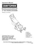
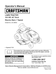
33-inch
Wide Cut Mower
B Model
No. 247.889980
17
/
55
\
54
46
43
46
37
45
68
36
21
74
45
58
11
42
39
51
6O
\
\
24
7O
59
35
6O
25
41
66
44
28
\
27
33=inch Wide Cut Mower B Model
No. 247.889980
738-04216A
Bolt, Shoulder:.625x 2.515x 3/8-16
42
741-0660A
FlangeBearing:.760x .941x 1.0
i Screw,Carriage:5/16-18x 2.25
43
787-01496-4028HeightAdjustmentBracket
i Screw,1/4-20x 0.500
44
787-01510-0637Link PivotBracket
787-01521-0637LeverPivotBracket
687-02427
LeverAssembly:LH
2
687-02426
LeverAssembly:RH
3
710-0572
4
710-0599
5
710-0606
i Screw,Cap: 1/4-20x 1.50
45
6
712-04063
iaut, FlangeLock:5/16-18
46
710-0604A
Screw,TT: 5/16-18x .625
7
912-0442
i Nut,Lock Cap: 1/4-20
47
738-04282
Screw,Shoulder:.32 x 1.8x 1/4-20
8
720-0274
Grip,1.0ID x 5.0 Lg
48
951-10541
FuelTank,2 Gal.
9
720-04072A
StarKnob 5/16-18
49
951-10514
FuelCap
10
736-0270
iWasher,Bell: .265x .75x .062
50
787-01507-4028 FuelTank MountingBracket
11
938-0140
i Screw,Shoulder,.435x .178-5/16
51
734-04243
Wheel,8 x 1.75
12
938-1226
*
941-0706
FlangeBearing,Wheel
13
946-04609
i Cable,ClutchWheel
52
710-1315
Screw,TT: 3/8-16x 1.25
14
946-04606
i Cable,Brake,Transmission:RH
53
710-0136
Screw,HH Cap: 1/4-20x 1.75
15
946-04610
i Cable,ClutchDeck
54
712-3006
Nut,Hex: 1/4-20
631-04339P
HandlePanel
Screw,Shoulder,.375x 1.355:1/4-20
16
946-04604
i Cable,Throttle/Choke:38 x 1.1
55
17
946-04608
i Cable,Brake,Transmission:LH
56
931-06935
TankCover
18
749-04330-0637LowerHandle
57
725-0157
CableTie
19
749-04331-0637UpperHandle:LH
58
710-0642
Screw,TT: 1/4-20x .75
20
749-04332-0637UpperHandle:RH
59
710-04666
Screw,1/4-20x .75
21
749-04333-06371
BraceTube
60
712-0271
Nut,Seres:1/4-20
22
787-01548-4028HandlePanel
61
712-04064
Nut,FlangeLock: 1/4-20
23
787-01490A-0637
CableMountBracket:RH
62
936-0463
Washer,Fiat:.25 x .63x .0515
787-01491A-06371
CableMountBracket:LH
63
925-04022B
HourIndicatorMeter
24
687-02255B-4028
FrameAssembly
64
925-1741
KeySwitch
25
687-02263-0637CasterWheelBracketAssembly
65
725-04439
Solenoid,12V
26
687-02419-0637DeckLift Assembly:RR
66
925-1707D
Battery
27
687-02265-0637DeckLift Assembly:Front
67
731-05319
Lens
28
710-0627
i Screw,HH Cap: 5/16-24x .750
68
751B221535
CasingClamp
29
925-1649
i LampSocket
69
747-04657
BatteryHold Down
30
710-04312
i Screw,HH Cap: 5/16-18x .50
70
751-10349
FuelHose
31
712-04065
i Nut, FlangeLock:3/8-16
71
726-0205
HoseClamp
951-10517A
Oil Drain
32
914-0145
Click Pin:.092x 1.64
72
33
34
720-0311
931-05684
HandleGrip 1/2
BeltCover33 WideCut Mower
73
751-3141-14
Oil DrainHose
74
710-1237
Screw,10-32X .625
35
731-05791
i Snap Spacer:.63ID x .75LG
75
925-1745A
Key,Ignition,Black
36
732-04418A
i Deck HeightLever
76
710-0896
Screw,1/4-20x 1.75
37
736-0242
i Washer,Bell:.340x .872x .060
77
925-04213
Lamp
78
777X41805
LabelReflector
38
736-0343
i Washer,Flat:.330x 1.25x .120
39
936-0351
Washer,Flat:.760ID x 1.50OD
*
725-04478
StarterWire
40
937-3000
Lube Fitting:3/16:LNC#70
*
925-04911
Wiring Harness
* Not pictured
29
33=inch Wide Cut Mower
B Model
No. 247.889980
11_
11
26
14
61
18
i
÷J
17
42
51
°\
73
49
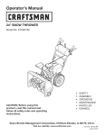
33-inch
Wide Cut Mower B Model
D=
No. 247.889980
I
O
17840-0637
TransaxleBracketMount
2
918-04639
Transmission4-Speed
3
710-0176
4
710-0376
5
710-04377
6
710-0513
7
710-0520
8
710-0347
9
710-3008
10
710-3015
i Screw,HH Cap: 1/4-20x .75"
11
911-1000
i Belt Keeper
12
712-04063
13
712-04064
14
712-04065
15
712-0700
16
17
D=
O
O
918-04439B
SpacerSpindleAssembly
i41
631-04252
MulchPlug
i Screw,HH Cap: 5/16-18x 2.75"
i42
987-02420
i Screw,HH Cap: 5/16-18x 1.00"
i43
Screw,HH Cap: 7/16-20x 2.75"
i44
IdlerArmAssembly
i687-02476-0691DeckAssembly33-inch
i710-0451
Bolt,Carriage:5/16-18x .75"
i Screw,HH Cap: 1/4-28x .625"
i45
710-0514
Screw,HH Cap:3/8-16x 1.00"
i Screw,HH Cap: 3/8-16x 1.50"
i46
710-0560
i Screw,HH Cap: 3/8-16x 1.75"
i47
710-04484
Screw,Carriage:3/8-16x 1.75"
Screw,LD: 5/16-18x .750"
Screw,HH Cap: 5/16-18x .75"
i48
710-3184A
Screw,HH Cap:3/8-16x 2.00"
i49
931-04244
ChuteDeflectorAssy(includesref.72-76)
i712-0417A
912-0641
Nut,Flange:5/8-18
i Nut, FlangeLock:5/16-18
i50
i51
i Nut, FlangeLock: 1/4-20
i52
912-3017
Nut,Hex 3/8-16
i Nut, FlangeLock:3/8-16
i53
732-04406
ExtensionSpring:TimingBelt Tension
i Nut, Flange:9/16-18
i54
732-04452
ExtensionSpring:Deck Brake
914-0145
i HairpinClip:092"x 1.64"Long
i55
736-0225
Washer,Lock
718-04407
i PulleyHub
i56
938-0347
Spacer,Shoulder:.625"x .169"
738-04162A
Nut,Hex
18
720-0142
iGrip
i57
19
731-05766
i TrailingShield
i58
942-04154A
Spacer,Shoulder:.884"x .190"
Blade:17.9"
20
732-04409
i ExtensionSpring
i59
754-04136
Belt,Timing
21
732-04443A
ExtensionSpring
i60
954-04139
Belt,V Type
22
736-0105
i Washer,Spring:.401"x .870"x .063"
i61
756-04129B
IdlerPulley4.25"
23
736-0322
i Washer,Flat:450"x 1.250"x .164"
i62
756-04280
IdlerPulley3.50"
24
736-0270
i Washer,Bell
i63
756-0616
25
736-04256
i Washer,Flat:.39"x .87"x .06"
i64
IdlerPulleyV-Type5.0"
78_01440-0637 IdlerTimingBracket
26
738-04166
i65
921-04041
27
747-04635A
i Belt KeeperRod
i66
737-04003D
28
747-04673
i Loop LinkCoupling
TransMountRod
i67
634-04285-0911Wheel 16x 4 x 8
i68
736-0242
Washer,Bell: .340"x .872"x .060"
710-0627
Screw,HH Cap:5/16-24x .75"
Spacer,Shoulder:.50"x .1475"
Water NozzleAdapter
Water Nozzle
29
747-04678A
30
954-04145A
i Belt, V Type
i69
31
756-04129B
710-1315
Screw,TT: 3/8-16x 1.25"
756-04258
i IdlerPulley:4.25"Dia.
Flat Sheave7.75"
i70
32
i71
710-04187
Screw,HL: 1/4-15x .50"
33
756-04260
i EnginePulley3.20"x 4.35"Dia.
34
756-04280
i72
i73
DeflectorPin
711-04027
787-01017A-0637
DeflectorHingeBracket
i74
732-04012
i75
726-04009
35
36
37
i IdlerPulley3.50"Dia.
787-01469B-0637
i Shift Rod, Lower
787-01470A-0637
i Shift Rod, Upper
38
787-01473-0637
i Belt Keeper
787-01523A
WheelDriveidlerBracket
39
918-04438B
i76
31
PushCap
Chute Deflector,33"SD Deck
977S30145
i DriveSpindleAssembly
DeflectorTorsionSpring
LabelChuteDeflector(notshown)
33=inch Wide Cut Mower
m Model
No. 247.887330
27
21
20,,_/22
29
I
I
\1
71B
o/
83
18
/
49
3O
50
157
30
51
52
47
64
/
31A
29B
13
56
69
64
65
57
58
59
/
13
15
63
31A
48
37
d
41
3/
40
MODELand SERIAL
NUMBERSHERE
32
157
34 /
87
63
29
/
35
33-inch
Wide Cut Mower B Model
No. 247.887330
D =
O
O
TC-772147
TransaxleCover
TC-790075
BrakeDisk
2
3
TC-780086A
TC-770128A
NeedleBearing(1/,,long)
TransaxleCase
37
TC-790007
BrakePad Plate
4
TC-776395
Countershaft
38
39
TC-799021A
TC-786026
BrakePad (pkg.of 2)
DowelPin .3125"x .750"
5
TC-776409
OutputShaft
40
736-3078
Washer.312"ID .059"
TC-790104
BrakeLever
6
T0-778364
Spur Gear(38T-PM/SER)
41
6A
T0-778369
Spur Gear(15T-PM/SER)
42
TC-792177
Screw 1/4-20x 1-3/8"
7
T0-778330
Spur Gear(11T-PM/SER)
43
912-0237
LockNut 5/16-24
44
TC-790025
BrakePad Holder
8
9
TC-792180A
TC-784352
Shift KeySet (Qty.2)
Shift Collar
46
TC-786086
Bracket
10
TC-784378
Shift Rod& ForkAssembly
47
T0-775146
Axle (10.719"long) (Incl.26)
11
TC-778334
BevelGear (30T-PM)
48
T0-775147
Axle (15.312"long) (Incl.26)
12
TC-778309
Input BevelPinion(13T-PM)
49
TC-778338
Spur Gear (27T-PM/IC)
13
TC-778368
BevelGear 13T(Incl. ref. 13& 14)
50
TC-778342
Spur Gear (22T-PM/IC)
14
TC-778368
BevelGear 13T(Incl. ref. 13& 14)
51
TC-778313
Spur Gear (19T-PM/IC)
15
17
T0-778370
TC-786188
RingGear (43T)
DrivePin
52
TC-778350
Spur Gear (16T-PM/IC)
56
TC-778337
Spur Gear (13T-PM/SER)
18
TC-786102
Spacer(1.130"x .695")
57
TC-778341
Spur Gear (18T-PM/SER)
20
TC-792077A
Ball (StainlessSteel5/16" dia.)
58
TC-778351
Spur Gear (21T-PM/SER)
21
TC-792211
Screw,3/8-16x 3/8"
59
TC-778349
Spur Gear (24T-PM/SER)
22
TC-792079
Spring
63
TC-786071
CountershaftSpacer1-1/8"x 3/8"
25
TC-792073A
Screw,1/4-20x 1-1/4"
25A
TC-792177
Screw,1/4-20x 1-3/8"
64
65
TC-786072
TC-780189
BrakeShaft Spacer1-3/8"x 3/8"
Washer.563"ID .062
26
TC-792125
RetainingRing-packageof 2
27
TC-792035
RetainingRing
66
67
TC-776472
TC-776396
inputShaft
BrakeShaft
28
29
TC-788040
TC-780072
RetainingRing
Washer.627"ID .031"
69
TC-792170
RetainingRing(.75"x .042")
70
TC-786187
Spacer(.890")
29A
TC-780160
ThrustWasher(.563"ID x .031")
71B
TC-788092
O-Ring
29B
TC-780051
ThrustWasher(.762"ID X .031")
76
TC-780090
Fiat Washer(1.128"ID x .058")
30
31
T0-780108
TC-780001
ShiftWasher(Cupped)
Washer.750"ID .56"
77
TC-788078A
RetainingRing(1.125"x .050")
79
TC-792144
Spring
31A
TC-780195
Washer.750"ID .062
82
TC-778333
Bevel(30T)& Spur Gear
32
TC-788083
Oil Seal 5/8"
83
TC-778338
Spur Gear(27T-PM/IC)
32A
TC-792001
O Ring(.823"OD)
34
TC-780194
Bushing(.563")
85
87
TC-792154
TC-788089A
Oil FillPlug
Oil Seal9/16" ID
35
TC-780193
FlangedBushing(.625"ID)
157
TC-788088A
Oil Seal3/4" ID
35A
TC-780197
FlangedBushing(.751"ID)
33
Briggs
and Stratton
219707=0712=B1
238 ®
1022
1034
1o29
83o_
870_
51 '_
850
13U _
1022
45
lO2_._
654
J
54%
1095 VALVE GASKET SET
868 _,
51A
1O22
51
883 _ "¢_
'_,
34
Briggs
and Stratton
219707=0712=B1
24O
lO8_!
95 6
987
¢-<f_
1266A
51
¢_ :::::::: :: _)
1266
_::::'_cct
,.(_ 1091
9p
127_)
lOS
104
!
'%= J
I
1036 EMISSIONS
LABEL
I
1127
1397@
121 CARBURETOR
51
104
_
lOS
51A
127 L'¢_}
95
OVERHAUL
617 10
KIT
773
987<_
®
633 bf:_
643
J.._J o
967
445
217 _)
1266A
35
Briggs
and Stratton
202
_
219707=0712=B1
209
Z_/
_"
216 _J'_f
521
_:_
1054
232
188
222
5O7
52O
@
359
373
415
1044
823
1005
_
613A
- _'-:-_
_)
23
36
- _'_,_
_'_
Briggs
and Stratton
219707=0712=B1
334 _
356
f_
__
_
635 s ,_/J
801 _,_
_
1051 °
544
@
783 _
513
803
311
579
802
1119
37
Briggs
and Stratton
219707=0712=B1
11
85O
358 ENGINE GASKET SET
883
12 _
\_
1O22
718_
2o@
25[
524 0
27 _>
/
_i_XX_
_ 177 0
J
51
.....
!_i_l
617 _
691 _
306
51A
868 @
307/!1_
616
404
614 ,[_
523 I ,_,
---_
_
177 q_>
43
524 0
38
56_
1266A ,f=:-_
Briggs
and Stratton
219707=0712=B1
794312
Gasket-intake
53
690227
Stud(Carburetor)
54
691148
Screw(IntakeManifold)
Sump-Engine
78
691003
Screw(FlywheelGuard)
691178
Lock-MufflerScrew
699045
CylinderAssembly
2
399265
Kit-Bushing/Seal(MagnetoSide)
3
391086s
Seal-Oil(MagnetoSide)
4
697106
5
792964
Head-Cylinder
81
7
273280s
Gasket-CylinderHead
94
793610
Kit-IdleMixture
9
697109
Gasket-Breather
95
690718
Screw(ThrottleValve)
(BreatherGasketand LiquidSealantare
interchangeable,Reference850)
98
695408
Kit-IdleSpeed
104
694918
Pin-FloatHinge
10
697157
Screw(BreatherAssembly)
105
696136
Valve-FloatNeedle
11
794683
Tube-Breather
108
698773
Valve-Choke
12
697110
Gasket-Crankcase
117
796079
Jet-Main(Standard)
13
690360
Screw(CylinderHead)
118
796332
Jet-Main(HighAltitude)
15
690946
Plug-OilDrain
121
698787
Kit-CarburetorOverhaul
16
796146
Crankshaft
125
794653
Carburetor
20
795387
Seal-Oil(PTOSide)
127
690727
Plug-Welch
22
692125
Screw(CrankcaseCover/Sump)
130
698774
Valve-Throttle
23
698281
Flywheel
131
698776
Kit-ThrottleShaft
694914
Float-Carburetor
24
222698s
Key-Flywheel
133
25
796155
PistonAssembly(Standard)
135
698780
Tube-FuelTransfer
794891
PistonAssembly(.020"Oversize)
137
698781
Gasket-FloatBowl
26
792306
RingSet (Standard)
141
698778
Kit-ChokeShaft
792643
698469
146
691639
Key-Timing
27
177
691031
Seal-O Ring(Dipstick)
28
697099
Pin-Piston
187
791805
Line-Fuel(Formed)
29
791633
Rod-Connecting
187A
791744
Line-Fuel(Formed)
32
791118
Screw(ConnectingRod)
188
691693
Screw(ControlBracket)
33
791934
Valve-Exhaust
192
691986
Adjuster-RockerArm
34
791935
Valve-Intake
202
691841
Link-MechanicalGovernor
35
691279
Spring-Valve(Intake)
209
792813
Spring-Governor(Brown)
36
691279
Spring-Valve(Exhaust)
216
691840
Link-Governor
37
697352
Guard-Flywheel
217
695409
Spring-ChokeReturn
40
690964
Retainer-Valve
222
694042
Bracket-Control
42
499586
Keeper-Valve
227
691374
Lever-GovernorControl
43
691968
Slinger-Governor/Oil
232
691842
Spring-GovernorLink
45
690564
238
691843
Cap-Valve
46
793880
Camshaft
240
394358s
Filter-Fuel
48
697740
ShortBlock
265
691024
Clamp-Casing
50
697361
Manifold-Intake
267
794904
Screw(CasingClamp)
51
692137
Gasket-intake
300
796000
Muffler
LRingSet(.020" Oversize)
Lock-PistonPin
i Tappet-Valve
39
Briggs
and Stratton
219707=0712=B1
|=
o o
BS-796414 Housing-Blower(Red)
BS-692138 SeaI-ORing(IntakeManifold)
305
BS-697102 Screw(BIowerHousing)(Long)
621
BS-692310 Switch-Stop
305A
BS-793376 Screw(BIowerHousing)(Short)
633
BS-699813 Seal-Choke/ThrottleShaft(Choke Shaft)
306
BS-697359 Shield-Cylinder
634
BS-698779 Spring/SealAssembly
307
BS-691003 Screw(CylinderShield)
635
BS-691909 Boot-SparkPlug
309
BS-693551 Motor-Starter
643
BS-697155 Retainer-AirFilter
310
BS-690323 Bolt(Starter Motor)
654
BS-690958 Nut(Carburetor)
311
BS-497608 BrushSet
691
BS-692407 Seal-GovernorShaft
324
BS-796308 Screen/CupAssembly
697
BS-690372 Screw(Drive Cap)
333
BS-795315 Armature-Magneto
718
BS-690959 Pin-Locating
334
BS-691061 Screw(MagnetoArmature)
729
BS-691224 Clip-Wire
337
BS-491055s Plug-Spark
741
BS-697128 Gear-Timing
356
BS-398808 Wire-Stop
773
BS-796448 Retainer
358
BS-697151 GasketSet-Engine
783
BS-693713 Gear-Pinion
359
BS-691077 Washer(GroundTerminal)
797
BS-693167 Nut(Brush Retainer)
373
BS-691612 Nut (GroundTerminal)
801
BS-691283 Cap-Drive
404
BS-691691 Washer(GovernorCrank)
802
BS-691286 Cap-End
415
BS-794129 Plug(RotatingScreen)
803
431
BS-697122 Elbow-intake
445
BS-698413 Filter-AirCleanerCartridge
474
BS-696459 Alternator
823
BS-698941 Screw(MufflerAdapter)
505
BS-691251 Nut (GovernorControlLever)
830
BS-691095 Stud-RockerArm
507
BS-691972 insulator
847
BS-790442 Dipstick/TubeAssembly
510
BS-693699 Drive-Starter
850
BS-100106 Sealant-Liquid
513
BS-692024 Clutch-Drive
520
BS-691084 Terminal-Ground
521
BS-690581 Shield-Cable
851
BS-692424 Terminal-SparkPlug
523
BS-699908 Dipstick
864
BS-796002 Adapter-Muffler
524
BS-691032 Seal-DipstickTube
868
BS-690968 Seal-Valve
525
BS-697184 Tube-Dipstick
883
BS-692236 Gasket-Exhaust
544
BS-692034 Armature-Starter
914
BS-691108 Screw(RockerCover)
552
BS-697144 Bushing-GovernorCrank
967
BS-697292 Filter-PreCleaner
562
BS-691119 Bolt(GovernorControlLever)
968
BS-697420 Cover-AirCleaner(Black)
579
BS-691029 Nut (StarterCable)
Housing-Starter
(Not ServicedSeparately,OrderStarter
Motor693551,Reference309)
(interchangeablewith RockerCover
Gasketand BreatherGasket)
BS-697422 Cover-AirCleaner(Red)
584
BS-794682 Cover-BreatherPassage
975
BS-698783 Bowl-Float
601
BS-791850 Hose-Clamp
987
BS-698777 Seal-ThrottleShaft
613
BS-691416 Screw(Muffler)(Long)
1005
BS-796082 Fan-Flywheel
613A
BS-691678 Screw(Muffler)(Short)
1022
BS-272475s Gasket-RockerCover
614
BS-691620 Pin-Cotter(GovernorCrank)
616
BS-692012 Crank-Governor
(RockerCoverGasketand LiquidSealant
are interchangeable,see Reference850)
4O
Briggs
and Stratton
219707=0712=B1
|=
=
e
e
BS-794659 Cover-Rocker
1026
BS-794573 Rod-Push(Exhaust)
1029
BS-697394 _ Rod-Push(Intake)
BS-691751 Arm-Rocker
1034
BS-690822 Guide-PushRod
1036
Label-Emissions(Availablefrom a Briggs&
StrattonAuthorizedDealer)
1040
BS-698368 Plate-Trim
1044
BS-698139 Screw(Flywheel)
1051
BS-691265 Ring-Retaining
1054
BS-280275 Tie-Cable
1059
BS-698516 Kit-Screw/Washer(Alternator)
1090
BS-691293 Retainer-Brush
1091
BS-691333 Cap-Limiter
1095
BS-795807 GasketSet-Valve
1119
BS-691183 Screw(Alternator)
1127
BS-695407 Screw(Float Bowl)
1263
BS-697124 Reed-Breather
1264
BS-697104 Screw(BreatherReed)
1266
BS-691917 Seal-ORing(IntakeElbow)(Red)
1266A
BS-697123 Seal-ORing(intake Elbow)(Large)
1267
BS-697419 Latch-BIowerHousing(Black)
BS-697424 Latch-BIowerHousing(Red)
1329
BS-2197070026G1 ReplacementEngine
41
777S30145
777D09788
777122793
777122808
777D13372
777S30117
777D13373
777122759
777122760
777122814
777122815
777122809
777X43688
;;1. Insert Mulch Plug's front tab into slot on outside of deck.
::2. Pivot Mulch Plug inboard into discharge opening,
3. Slide rearward until slot bottoms out against edge of discharge opening.
4. Lower Discharge Chute to lock Mulch Plug in place.
42
Congratulationson makinga smartpurchase.YournewCraftsman@
productis designedand manufacturedfor yearsof dependableoperation. But likeall products,it may requirerepairfrom time to time.That's
whenhavinga RepairProtectionAgreementcansave youmoneyand
aggravation.
Here'swhat the RepairProtectionAgreement*includes:
* Expert service byour 10,000professionalrepairspecialists
o Unlimitedserviceand no chargefor partsand laboron all
coveredrepairs
o Product replacementup to $1500if yourcoveredproductcan't be
fixed
• Discountof 10%from regularprice of serviceand relatedinstalled
parts notcoveredby theagreement;also, 10%off regularpriceof
preventivemaintenancecheck
• Fast help by phone- we call it RapidResolution- phone support
from a Searsrepresentative.Thinkof usas a "talkingowner's
manual."
43
Onceyou purchasethe Agreement,a simplephonecall is all that it
takesfor youto scheduleservice.Youcan call anytimedayor night,or
schedulea serviceappointmentonline.
The RepairProtectionAgreementis a risk-freepurchase.If youcancel
for any reasonduringthe productwarrantyperiod,wewill providea full
refund.Or,a proratedrefundanytimeafter the productwarrantyperiod
expires.Purchaseyour RepairProtectionAgreementtoday!
Somelimitationsand exclusionsapply. For pricesand additional
informationin the U.S.A. call 1-800-827-6655.
*Coverage in Canadavaries on some items. Forfull details call
Sears Canadaat 1-800-361-6665.
Sears Installation Service
ForSearsprofessionalinstallationof homeappliances,garagedoor
openers,waterheaters,and othermajorhomeitems,in the U.S.A.or
Canadacall 1-800-4-MY-HOME®.
FEDERAL
and/or CALIFORNIA
EMISSION CONTROL WARRANTY STATEMENT
YOUR WARRANTY
RIGHTS AND OBLIGATIONS
MTDConsumerGroupInc,the United StatesEnvironmentalProtectionAgency (EPA),and, forthose productscertifiedfor sale in the stateof California,the
CaliforniaAir ResourcesBoard(CARB)are pleasedto explainthe emission(evaporativeand/or exhaust)controlsystem(ECS) warrantyon youroutdoor 2006
andlater smalloff-roadspark-ignitedengine andequipment(outdoorequipmentengine)In California,new outdoorequipmentengines mustbe designed,built and
equippedto meetthe State'sstringentanti-smog standards(in otherstates, 1997andlater modelyear equipmentmustbe designed,built, and equippedto meet
the U.S. EPAsmalloff-road, sparkignitionengine regulations.MTDConsumerGroupInc mustwarrantthe ECSon your outdoorequipmentenginefor the periodof
time listed belowprovidedtherehas been no abuse, neglector impropermaintenanceof outdoor equipmentengine.
Your ECSmay includeparts such as the carburetor,fuel-injectionsystem,the ignitionsystem,catalyticconverter,fuel tanks,fuel lines,fuel caps, valves,canisters,
filters,vapor hoses,clamps,connectors,andotherassociatedemission-relatedcomponents.
Wherea warrantableconditionexists, MTDConsumerGroupIncwill repairyouroutdoor equipmentengine at no cost to you includingdiagnosis,parts and labor.
MAN UFACTURER'S
WARRANTY
COVERAGE:
This emissioncontrolsystemis warrantedfor two years. If any emission-relatedpart on your outdoorequipmentengine is defective,the part will be repairedor
replacedby MTDCONSUMERGROUPINC.
OWNER'S WARRANTY
RESPONSIBILITIES:
Asthe outdoorequipmentengineowner,you are responsiblefor performanceof the requiredmaintenancelisted inyour owner'smanual.MTDConsumerGroup
Inc recommendsthat you retain all receiptscoveringmaintenanceon youroutdoor equipmentengine,but MTDConsumerGroupInc cannotdeny warrantysolely
forthe lackof receipts.
Asthe outdoorequipmentengineowner,you shouldhoweverbe awarethat MTDConsumerGroupInc may denyyou warrantycoverageif your outdoorequipment
engineor a part has failed due to abuse, neglect,or impropermaintenanceor unapprovedmodifications.
Youare responsiblefor presentingyouroutdoor equipmentengineto MTDConsumerGroupInc's distributioncenteror servicecenteras soon asthe problem
exists.The warrantyrepairsshouldbe completedin a reasonableamountof time, not to exceed30 days. If you havea questionregardingyour warrantycoverage,
you shouldcontactthe MTDConsumerGroupIncService Departmentat 1-800-800-7310or via email at http://support.mtdproducts.com
GENERAL
EMISSIONS WARRANTY
COVERAGE:
MTDConsumerGroupIncwarrantsto the ultimatepurchaserand eachsubsequentpurchaserthat the outdoor equipmentengine is: Designed,built and equipped
so asto conformwithall applicableregulations;and freefrom defects in materialsand workmanshipthatcausethe failureof a warrantedpart to be identicalin all
materialrespectsto that part as describedin MTDConsumerGroup Inc'sapplicationfor certification.
The warrantyperiodbeginson the date the outdoor equipmentengine is deliveredto an ultimate purchaseror first placedinto service.The warrantyperiodis two
years.
Subjectto certain conditionsand exclusionsasstated below,the warrantyon emission-relatedparts is asfollows:
1. Any warrantedpart that is not scheduledfor replacementas requiredmaintenancein the written instructionssupplied, is warrantedforthe warrantyperiod
statedabove. Ifthe part fails duringthe periodof warrantycoverage,the part will be repairedor replacedbyMTDConsumerGroupInc accordingto subsection
(4) below. Anysuch part repairedor replacedunderwarrantywill be warrantedfor the remainderof the period.
2. Any warrantedpart that is scheduledonly for regularinspectionin the writteninstructionssupplied is warrantedforthe warrantyperiodstatedabove.Any such
part repairedor replacedunderwarrantywill be warrantedforthe remainingwarrantyperiod.
3. Any warrantedpart that is scheduledfor replacementas requiredmaintenancein the written instructionssuppliedis warrantedfor the periodof time beforethe
first scheduledreplacementdatefor that part. If the partfails beforethe first scheduledreplacement,the part will be repairedor replacedby MTDConsumer
GroupInc accordingto subsection(4) below.Any such part repairedor replacedunderwarrantywill be warrantedfor the remainderof the periodprior to the
first scheduledreplacementpointfor the part.
4. Repairor replacementof any warrantedpart underthe warrantyprovisionshereinmustbe performedat a warrantystationat no chargeto the owner.
5. Notwithstandingthe provisionsherein,warrantyservicesor repairswill be providedat all of our distributioncentersthatare franchisedto servicethe subject
enginesor equipment.
6. The outdoorequipmentengine ownerwill not be chargedfor diagnostic laborthat is directlyassociatedwithdiagnosisof a defective,emission-relatedwarrantedpart, providedthat suchdiagnosticwork is performedat a warrantystation.
7. MTDConsumerGroupInc is liablefor damagesto otherengine or equipmentcomponentsproximatelycausedby a failure underwarrantyof any warranted
part.
8. Throughoutthe off-roadengineand equipmentwarrantyperiodstatedabove, MTDConsumerGroupInc will maintaina supply of warrantedparts sufficientto
meetthe expecteddemandfor such parts.
9. Any replacementpart may be usedinthe performanceof any warrantymaintenanceor repairsand mustbe providedwithoutchargeto the owner.Suchuse will
not reducethe warrantyobligationsof MTDConsumerGroupInc.
10. Add-onor modifiedpartsthat are not exemptedbythe Air ResourcesBoardmay not be used.The use of any non-exemptedadd-on or modifiedparts by the
ultimatepurchaserwill be groundsfor disallowinga warrantyclaims. MTDConsumerGroup Incwill not be liableto warrantfailuresof warrantedparts caused
bythe use of a non-exemptedadd-onor modifiedpart.
WARRANTED
PARTS:
The repairor replacementof any warrantedpart otherwiseeligiblefor warrantycoveragemay be excludedfrom such warrantycoverageif MTDConsumerGroup
Inc demonstratesthatthe outdoor equipmentengine has beenabused,neglected,or improperlymaintained,and thatsuch abuse, neglect,or impropermaintenancewasthe direct causeof the needfor repairor replacementof the part. That notwithstanding,any adjustmentof a componentthat hasa factory installed,
and properlyoperating,adjustmentlimitingdevice is still eligible for warrantycoverage. Further,the coverageunderthis warrantyextendsonly to partsthat were
presenton the off-roadengineand equipmentpurchased.
Thefollowing emissionwarrantypartsare covered(if applicable):
(1) FuelMeteringSystem
•
Cold start enrichmentsystem(softchoke)
•
Carburetorand internalparts (or fuel injectionsystem)
•
Fuelpump
•
Fueltank
(2) Air InductionSystem
•
Air cleaner
•
Intakemanifold
(3) IgnitionSystem
•
Spark plug(s)
•
Magneto ignitionsystem
(4) ExhaustSystem
•
Catalyticconverter
•
SAI (Reed valve)
(5) MiscellaneousItemsUsedin AboveSystem
•
Vacuum,temperature,position,time sensitivevalvesand switches
•
Connectorsandassemblies
(6) EvaporativeControl
•
Fuelhose
•
Fuelhoseclamps
•
Tetheredfuel cap
•
Carboncanister
•
Vapor lines
GDOC-100223
Look For Relevant Emissions Durability Period and
Air index information On Your Engine Emissions Label
Engines that are certified to meet the California Air Resources Board (CARB) Tier 2 Emission Standards must
display information regarding the Emissions Durability Period and the Air Index. Sears, Roebuck and Co., U.S.A.
makes this information available to the consumer on our emission labels.
The Emissions Durability Period describes the number of hours of actual running time for which the engine is
certified to be emissions compliant, assuming proper maintenance in accordance with the Operating & Maintenance Instructions. The following categories are used:
Moderate:
Engine is certified
to be emission compliant
for 125 hours of actual engine running time.
Intermediate:
Engine is certified
to be emission compliant
for 250 hours of actual engine running time.
Extended:
Engine is certified
to be emission compliant
for 500 hours of actual engine running time.
For example, a typical walk-behind lawn mower is used 20 to 25 hours per year. Therefore, the Emissions
Durability Period of an engine with an intermediate rating would equate to 10 to 12 years.
The Air Index is a calculated number describing the relative level of emissions for a specific engine family. The
lower the Air Index, the cleaner the engine. This information is displayed in graphical form on the emissions label.
After
After July 1, 2000 certain
Environmental Protection
sions Compliance Period
for which the engine has
July 1,2000, Look For Emissions
Compliance
On Engine Emissions
Compliance
Label
Period
Sears, Roebuck and Co., U.S.A. engines will be certified to meet the United States
Agency (USEPA) Phase 2 emission standards. For Phase 2 certified engines, the Emisreferred to on the Emissions Compliance label indicates the number of operating hours
been shown to meet Federal emission requirements.
For engines less than 225 cc displacement,
For engines of 225 cc or more, Category
Category
C = 125 hours, B = 250 hours and A = 500 hours.
C = 250 hours, B = 500 hours and A = 1000 hours.
This is a generic representation of the emission label typically found on a certified engine.
FAMILY YBSXS.3192VA
274812
GDOC-100182
Rev.A
46
47
Declaraci6n de garant[a ..................................................
Instrucciones sobre seguridad .......................................
Gu[a para pendientes ......................................................
Etiquetas de seguridad ...................................................
Montaje ...........................................................................
Conozca su cortadora de cesped ..................................
GARANTiA
COMPLETA
48
49
51
52
53
56
Funcionamiento ...............................................................
59
Servicio y Mantenimiento ............................................... 61
Almacenamiento fuera de temporada ............................ 70
Aditamentos y Accesorios ..............................................
70
Soluci6n de problemas ...................................................
71
NOmero de servicio ............................... Cubierta posterior
Y PROFESIONAL
DE CRAFTSMAN
En condicionesnormalesde funcionamientoy mantenimientoconformealas instrucciones
suministradas,si este productoCraftsman
Profesionalfalladebido a defectosen los materialeso en la manode obra dentrode los dos aSosde la fecha de compra,comuniquesecon
1-800-4-MY-HOME®paraorganizarsu reparaci6nsincargo(o reemplazosi resultaraimposiNerepararlo).
La garanfias61oset&v&lidaduranteun aSoa partirde la fecha de comprasi este productose usaen cualquiermomentopara fines comerciales
o de alquiler.
EstagarantiacubreONICAMENTElosdefectosen los materialesyen la manode obra. SearsNOpagar&por:
•
Elementosque se desgastanpor el usonormal,incluyendoentreotrospero no limitadoalas cuchillas,bujias,filtrosde aire,correas,y
filtrosde aceite.
•
Serviciosde mantenimientoest&ndar,cambiode aceiteo reajustes.
Cambiode Ilantaso reparacionesocasionadospor pinchadurasconobjetosdel exteriorcomo clavos,espinas,toconeso vidrios,etc.
•
Reemplazoo reparaci6nde neum&ticoso ruedascomo resultadodel desgastenormal,un accidente,o funcionamientoo mantenimiento
incorrectos.
•
Reparacionesrequeridascomo resultadodel abusodel operador,incluyendopero no limitadoa daSoocasionadopor objetosque impactan
la m&quinay que tuercenel bastidoro cig(JeSal,
o debidoa que el motorfue aceleradoen exceso.
•
Reparacionesnecesariasdebidoa negligenciadel operador,incluyendoentre otros,daSosmec&nicoy el_ctricoocasionadopor un almacenamientono apropiado,no utilizarel aceitede gradoy/o cantidadno apropiada,no mantenerel &reade cubiertasin residuosinflamables,o
por no dar mantenimientoal equipode acuerdocon las instruccionescontenidasen el manualdel propietario.
Limpiezao reparacionesal motor(sistemade combustible)provocadaspor un combustiblecontaminadou oxidado(viejo).En general,el
combustibledebe utilizarseen un periodono mayorde 30 dias a partirde su adquisici6n.
El deterioroy desgastenormalde losacabadosexteriores,o reemplazode la etiquetadel producto.
•
Estagaranfiaseaplica solamentemientrasel productose encuentredentrode los EstadosUnidos.
Estagaranfiale otorgaderechoslegalesespedficos,pero ustedpodria gozarde otros derechosen raz6nde su lugarde residencia.
Sears, Roebuck and Co., Hoffman Estates, IL 60179
Caballosde fuerza:12.5
Aceitedel motor: SAE30
NSmero de modelo
Combustible:
Gasolinasin plomo
Bujia:
Motor:
Champion®RC12YC
Briggs& StrattonPowerBuiltTM
Fechade compra
Registreel nQmerode modelo,nQmerode seriey fechade compra
m&sarriba.
© SearsBrands,LLC
NSmero de serie
4.8
Estam&quinafue construidapara ser operadade acuerdo con las reglas
de seguridad contenidasen este manual.AI igual quecon cualquiertipo
de equipo motorizado,un descuido o error por partedel operadorpuede
producir lesionesgraves.Esta m&quinaes capazde amputarmanos y pies
y de arrojar objetoscon gran fuerza. Deno respetarlas instruccionesde
seguridadsiguientesse puedenproducirlesionesgraveso la muerte.
instrucciones
importantes
deseguridad
que
sedeben
respetar
para
evitar
poner
enpeligro
suseguridad
Lapresencia
de
este
simbolo
indica
que
setrata
de
personal
y/omaterial
yladeotras
personas.
Lea
ysiga
todas
lasinstrucciones
deestemanual
antes
deponer
enfuncionamiento
estam&quina.
Sinorespeta
estas
instrucciones
podria
provocar
lesiones
personales.
Cuando
veaeste
simbolo,
ipreste
atenci6n
a
laadvertencia!
El escapedel motorde este producto,algunosde suscomponentesy
algunoscomponentesdelvehiculocontieneno liberansustanciasquimicas
que elestado de Californiaconsideraque puedenproducirc_ncer,defectos
de nacimientou otros problemasreproductivos.
Su responsabilidad:Restrinjael usode esta rn_.quinarnotorizada
a las personasque lean,cornprendany respetenlas advertenciase
instruccionesque aparecenen este manualy en la rn&quina.
N QOS
Puedenocurrir
accidentes
tr&gicos
sieloperador
noest_
atento
a lapresencia
denifios.
PorIogeneral
a losnifios
lesatraen
lascortadoras
y laactividad
de
cortar
elcesped.
No entienden
losriesgos
nilospeligros.
Nuncaasumaquelos
nifios
permanecer&n
enelmismolugar
dondelosvioporQltima
vez.
•
Mantenga
a losnifios
fuera
del&readetrabajo
y bajo
estricta
vigilancia
de
unadulto
responsable
adem_sdeloperador.
•
Estealerta
yapaguelapodadora
siunnifio
ingresa
al_rea.
•
Antesde moversehaciaarrasy mientrasIoeste haciendo,mirehacia
atr_sy cuide queno hayanifios.
•
Tengaextremaprecauci6ncuandose aproximea esquinasciegas,
entradasde puertas,_rbolesu otrosobjetosque puedanobstaculizarlela
vistade un nifio quepudiesecorrer haciala cortadora.
•
Mantengaa los nifiosalejadosde losmotoresen marchao calientes.
Puedensufrirquemadurascon unsilenciadorcaliente.
•
Nuncapermitaque nifiosmenoresde 14afios operenesta m&quina.Los
nifiosmayoresde 14 afios debenleery entenderlas instruccionesde
operaci6ny reglasde seguridadcontenidasen este manual,y debenset
entrenadosy supervisadospor suspadres.
FUNCIONAiVlIENTO
•
•
•
•
•
•
•
•
•
•
•
GENERAL
Leacuidadosamentetodas lasinstruccionescontenidasen este manual
antesde intentarmontarlam&quina.Lea,comprenday respetetodaslas
instruccionesquefiguranen la m&quinay en el o losmanualesantesde
hacerlafuncionar.Antesde operareste equipo,familiaricesetotalmente
con loscontrolesy el usocorrectodel mismo.Guardeeste manualen un
lugarseguropara consultasfuturasy peri6dicas,asi comoparasolicitar
repuestos.
Esta m&quinaes un equipode precisi6n,no unjuguete.PorIotanto,tenga
muchocuidadoen todo momento.Estaunidadfue disefiadapararealizar
unatarea:cortarelcesped.Nola utiliceparaningL_n
otrofin.
Nopermitanuncaque losnifios menoresde 14afios utilicenesta
m_quina.Los nifiosmayoresde 14afios debenleery entenderlas
instruccionesde operaci6ncontenidasen este manual,y debenset
entrenadosy supervisadospor suspadres.$61ose debepermitirusar
esta m_quinaa individuosresponsablesy familiarizadoscon susreglas
de seguridad.
Reviseminuciosamenteel &teadondese utilizar&el equipo.Retiretodas
laspiedras,palos,Ilantas,huesos,juguetesy otrosobjetosextrafiosque
podrianhacertropezary caero set recogidosy arrojadospor laacci6n
de lascuchillas.Los objetosarrojadospor lam_quinapuedenproducir
lesionesgraves.Planifiqueel patr6nde cortedel cespedque hade seguir
paraevitarla descargade materialhacia loscaminos,lasveredas,los
observadores,etc. Eviteadem&sdescargarmaterialcontralasparedes
y obstruccionesquepodrianprovocarqueel materialdescargadorebote
contrael operador.
Paraayudara evitarel contactocon lacuchillao unalesi6npot un objeto
arrojado,mantengaseen lazonadel operadordetr_sde lasmanijasy
mantengaa los nifios,observadores,ayudantesy mascotasapartadosal
49
•
•
•
•
•
•
•
•
menos25 metrosde lacortadoramientrasest_ en operaci6n.Detengala
m&quinasi alguienentraen lazona.
Paraprotegerselosojos,utilicesiempregafaso lentesde seguridad
mientrasoperala m&quinao mientraslaajustao repara.Losobjetos
arrojadosquerebotanpuedenproducirlesionesocularesgraves.
Utilicezapatosdetrabajoresistentes,de suelafuerte,y pantalonesy
camisasajustados.Se recomiendavestircamisay pantal6nparacubrir
brazosy piernasy usarzapatoscon punterade acero.Nuncaopereesta
m_quinadescalzo,con sandalias,zapatosresbalososo livianos(pot ej.
de Iona).
Nopongalasmanoso los piescercade laspiezasrotatoriasnidebajo
de laplataformade corte. El contactocon lascuchillaspuedeproducirla
amputaci6nde manosy pies.
Unacubiertade descargafaltanteo dafiadapuedeprovocarel contacto
con la cuchillao lesionespot objetosarrojados.
Muchaslesionesocurrencomoresultadode pasarla cortadorasobre
lospiesduranteunacaida provocadaal patinarseo tropezarse.No
se sostengade lacortadorasi seest_ cayendo,sueltela manija
inmediatamente.
Nuncatire lacortadorahacia ustedmientrascamina.Si deberetroceder
con la podadoraparaevitarunaparedu obst&culo,mireprimeroabajoy
atr_s paraevitartropezarsey luegosiga estos pasos:
a. Retrocedade la podadorahastaestirarcompletamentesus brazos.
b.AsegOresequeest&bienequilibradoy bienparado.
c.Tire lentamentehaciaarras,no m_sall_de la mitadde la distanciaentre
ustedy lacortadora.
d. Repitaestos pasossegL_n
sea necesario.
Noopereesta cortadorabajo losefectosdelalcoholo lasdrogas.
Noengancheel mecanismoautopropulsadoen lasunidadesequipadas
mientrasarrancael motor.
La manijade controlde la cuchillaes un dispositivode seguridad.
Nuncaintenteevitarsufuncionamiento.De hacerlonofuncionarianlos
dispositivosde seguridady podrianproducirselesionespersonalespor
el contactocon lascuchillasrotatorias.La manijade controlde lacuchilla
debefuncionarbien en ambasdireccionesy regresarautom_ticamentea
laposici6ndesconectadacuandose lasuelta.
Nuncaoperela cortadorasobrecespedhOmedo.Siempreeste segurode
su equilibrio.Si tropiezay cae puedelesionarsegravemente.Si siente
que pierdeelequilibrio,suelteinmediatamentela manijade controlde la
cuchillay la cuchilladejar&de rotarentres segundos.
Corteel cespedsolamentecon luzde dia o con unabuenaluzartificial.
Camine,nuncacorra.
Detengala cuchillacuandocrucesendas,senderoso caminosde grava.
Si la m_quinacomenzaraavibrar de maneraanormal,detengael motor
y busqueinmediatamentelacausa.La vibraci6npot Io generales una
advertenciade algOnproblema.
Apagueelmotory esperehastaque lacuchillasedetenga
completamenteantesde retirarel colectorde cespedo de desbloquearel
canal.La cuchillacontinOarotandopot unoscuantossegundosdespues
•
•
•
•
que
elmotor
sehaapagado.
Nunca
coloque
ninguna
parte
delcuerpo
en
el_rea
delacuchilla
hasta
que
este
seguro
que
lacuchilla
hadejado
de
girar.
Nunca
opere
lacortadora
sinotiene
colocados
yfuncionando
elescudo
posterior
apropiado,
lacubierta
dedescarga,
elcolector
decesped,
lamanija
decontrol
delacuchilla
yotros
dispositivos
deseguridad
y
protecci6n.
Nunca
opere
lacortadora
silosdispositivos
deseguridad
est_n
da_ados.
SinoIohace,
pueden
producirse
lesiones
personales.
Elsilenciador
yelmotor
secalientan
ypueden
causar
quemaduras.
No
lostoque.
Utilice
solamente
piezas
yaccesorios
originales
def_brica.
SinoIohace,
pueden
producirse
lesiones
personales.
Sisepresentan
situaciones
que
noest_n
previstas
eneste
manual,
sea
cuidadoso
yuse
elsentido
comQn.
Contacte
consucentro
deservicio
Sears
para
obtener
ayuda.
FUNCIONAIVlIENTO
•
•
•
•
•
•
EN PENDIENTES
Las pendientesson un factorimportanteen losaccidentesocasionadospor
derrapesy caidasy puedenproducirlesionesgraves.La operaci6nen pendientes
requieremuchaprecauci6n.Si nose sienteseguroen unapendiente,no realice
elcorte.Parasuseguridad,useel indicadorde pendientesquese incluyecomo
partede estemanualparamedirla pendienteantesde operarla unidaden una
zonainclinada.Si lapendientesuperalos 15grados,no realiceel corte.
HagaIo siguiente:
•
Corteelcespedde la pendienteen sentidotransversal,nuncahacia arriba
y abajo.Tengasumocuidadoalcambiarde direcci6nen unapendiente.
•
Esteatentoa losagujeros,surcos,rocas,objetosocultoso bultosque
puedanprovocarque seresbaleo se tropiece.El cespedalto puede
ocultarobst&culos.
•
Siempreeste segurode queest&bien afirmado.Si tropiezay cae
puedelesionarsegravemente.Si sientequepierdeel equilibrio,suelte
inmediatamentela manijade controlde la cuchillay lacuchilladejar_de
rotaren 3 segundos.
NohagaIosiguiente:
•
Nocorte elcespedcercade hundimientos,zanjaso terraplenes,podria
perderelequilibrio.
•
Nocorte elcespeden pendientesmayoresde 15gradoscomose muestra
en el indicadorde pendiente.
•
Nocorte elcespedhQmedo.Si no est_firmementeparado,puede
resbalarse.
Servicio general:
•
Nuncaenciendael motoren espacioscerradoso en unazonacon poca
ventilaci6n.El escapedel motorcontienemon6xidode carbono,un gas
inodoroy letal.
•
Antesde limpiar,repararo inspeccionarla m&quina,compruebe
que lacuchillay todaslas partesquese muevense hallandetenido.
Desconecteel cablede labujia y p6ngalohaciendomasacontrael
motorparaevitarquese enciendaaccidentalmente.
•
Reviselospernosde montajede lacuchillay del motora intervalos
frecuentesparaverificarqueestenbien apretados.Inspeccione
adem&svisualmentela cuchillaen buscade daSos(abolladuras,
desgaste,roturas,etc).Reemplacela cuchillaQnicamentecon equipo
originaldelfabricante(OEM)listadoen este manual,i EIuso de piezas
que no cumplencon lasespecificacionesdel equipooriginalpodria
tenet comoresultadoun rendimientoincorrectoy adem_sponeren
riesgola seguridadk
•
Lascuchillasde lascortadorasson muy afiladasy podriancortarlo.
Envuelvala cuchillao utiliceguantesy extremelasprecauciones
cuandoefectQemantenimiento.
•
•
SERVIClO
NuncaIleneen excesoel dep6sitode combustible.Lleneel tanquea no
m&sde Y2pulgadapor debajode la basedel cuellodeltap6n de carga,
parapermitirla expansi6ndel combustible.
Vuelvaa colocarlatapa de la gasolinay ajL]stelabien.
Limpiela gasolinaquese puedahaberderramadosobreel motoro el
equipo.Trasladela m_quinaaotra zona.Espere5 minutosantesde
encenderel motor.
Nuncaalmacenela m_quinao el recipientede combustibleen un
espaciocerradodondehayafuego,chispaso aparatoscon pilotocomo
porejemplo,calentadoresde agua,calefactores,hornos,secadoresde
ropau otrosaparatosa gas.
Parareducirel riesgode incendiomantengalam_quinalimpia
de pasto,hojasy de acumulaci6nde otros escombros.Limpie
losderramesde aceiteo combustibley saquetodos losresiduos
embebidosde combustible.
Permitaque lam_quinase enfriepot Iomenos5 minutosantesde
almacenarla.
Mantengatodoslospernos,tuercasy tornillosbien ajustadospara
asegurarsede quela m_quinaseencuentraen condicionessegurasde
operaci6n.
Nuncaintentealterarlosdispositivosde seguridad.Controle
peri6dicamentequefuncionencorrectamente.
Despuesde golpearalgQnobjetoextraSo,detengael motor,
desconecteelcable de la bujiay col6quelohaciendomasacontrael
motor.Inspeccioneminuciosamentela m_quinaparadeterminarsi est_
daSada.RepareeldaSoantesde encenderlay operarla.
Nuncaintenteajustarunaruedao laaltura de cortemientrasel motor
est&en marcha.
Manejo seguro de la gasolina:
•
Paraevitarlesionespersonaleso da_os materialesseasumamente
cuidadosoal manipularlagasolina.La gasolinaes sumamenteinflamable
y susvaporespuedencausarexplosiones.Si sederramagasolinaencima
o sobrela ropase puedelesionargravementeya quese puedeincendiar.
•
Lavesela piely c_mbiesede ropa de inmediato.
•
Utilices61olosrecipientesparagasolinaautorizados.
•
NuncaIlenelosrecipientesen el interiorde un vehiculoo cami6no caja
de remolquecon recubrimientospl&sticos.Antesde Ilenarlos,coloque
siemprelosrecipientesen el suelo y lejosdel vehiculo.
•
Retireel equipoa gasolinadel cami6no remolquey Ileneloen elsuelo.Si
esto noes posible,Ileneelequipoen un remolquecon contenedorport_til,
en vezde desdeunaboquilladispensadorade gasolina.
•
Mantengalaboquilla en contactocon elhordedel dep6sitode
combustibleo con laaberturadel recipienteen todo momento,hasta
terminarde cargar.Noutiliceun dispositivopara abrir/cerrarla boquilla.
•
Apaguetodosloscigarrillos,cigarros,pipas y otrasfuentesde
combusti6n.
•
•
•
Mantengao reemplacelasetiquetasde seguridad,segQnsea
necesario.
•
Respetelasleyesy normasaplicablespara disponeradecuadamente
de losdesechos.La disposici6ninapropiadade liquidoso materiales
puededaSarel medioambiente.
•
Nuncacarguecombustibleen la m&quinaen interioresporquelosvapores
inflamablespodrianacumularseen el _rea.
Nuncasaquelatapa de lagasolinaniagreguecombustiblemientrasel
motorest&calienteo en marcha. Permitaqueel motorse enfriepot Io
menosdos minutosantesde volvera cargarcombustible.
5O
•
•
•
Loscomponentesdel colectorde cesped,la cubiertade descargay el
escudoposterior,est&nsujetosa desgastey daSosquepodriandejar
expuestaslaspiezasm6vileso permitirquese arrojenobjetos.Para
protegersu seguridad,verifiquefrecuentementetodosloscomponentes
y reempl_celosinmediatamentes61ocon piezasde losfabricantes
del equipooriginal,listadosen este manual,iEIuso de piezasque
nocumplencon lasespecificacionesdel equipooriginalpodriatener
comoresultadoun rendimientoincorrectoy adem_sponeren riesgola
seguridadk
Nocambielaconfiguraci6ndelreguladordel motorniexcedala
velocidaddel mismo.El reguladorcontrolalavelocidadm_ximasegura
de funcionamientodel motor.
o
-'o
¢d
03
03
_, ==8
¢d
movimientopodriavoltearsey causarlesionesseveras.Si en una pendienteopera una podadoraubicadodetr_sde la misma,es
No podeen inclinacionesmayoresa 15grados(elevaci6naproximadade 2 1/2 piespor cada 10pies). Unapodadoraen
extremadamentedificil mantenerel equilibrioy podriaresbalarsey sufrir lesionesgraves.
o
o
03
"0
03
0
0
0
03
03
03
03
03
._o
o
Z
0
E
03
03
c_- E
,_ ._
2x
03
03
03
,g" _
-o
o
ADVERTENCIA
Este sfmboloindicainstrucciones
de seguridadimportantes
que de
no seguirse,se podria poneren peligro la seguridadpersonaly/o
la propiedadsuyay de terceros.Leay sigatodas las instrucciones
en este manualantes de iniciarla operaci6nde esta m_.quina.En
caso de no seguirestasinstruccionespodria provocarlesiones
personales.Cuandoveaeste simbolo
SIGALA ADVERTENCIA
Su responsabilidad:S61opermitaque usenesta m_.quinael_ctrica
las personasque lean,comprendany respetenlas advertenciasy
las instruccionesqueaparecenen este manualyen la m_.quina.
52
IMPORTANTE:Esta unidadse enviasin aceiteen el motor.Despu_s
del rnontaje,consultela p_.gina49 paralos detallesdel combustibley
el aceite.
Mientrassostieneel canalde descargacon su rnanoizquierda,
extraigacon la rnanoderechala trabade seguridad,sujet_.ndola
entrelos dedospulgare indicey rot&ndolaen el sentidode las
agujasdel reloj.
IMPORTANTE:Las referenciasa losladosderechoo izquierdode
la cortadorade c_sped se hacenobservandola rn_.quinadesdela
posicidnde operacidn.
La trabade seguridadse usa Qnicarnenteparael ernbalaje.Retirey
desechela traba antesde operar la cortadorade cesped.
La plataformade lacortadorade cespedpuedearrojarobjetos. En caso
de operar la cortadorade cesped sincolocar el canal de descargaen la
posici6nadecuadapara elfuncionamiento,podrianproducirsegraves
lesionespersonalesy/o daSosmateriales.
La plataforrnade la cortadorade cespedpuedearrojarobjetos.
Encaso de operarla cortadorade c_sped sincolocar la cubierta
de descargaen la posici6nde funcionarnientoadecuada,podrian
producirsegraveslesionespersonalesy/o daSosrnateriales.
Desconecteel cable de la bujia y p6ngalohaciendomasacontrael motor
para evitarquese enciendaaccidentalmente.
INSTALACION
PIEZAS SUELTAS
DENTRO
DE LA CAJA
NOTA:El borne positivode la bateriaest&rnarcadocornoPos(+). El
bornenegativode la bateriaest,. rnarcadocornoNeg (-).
El cablepositivo(grueso,de color rojo) vienede f&bricasujetoal
bornepositivode la bateria(+) por medicde un perno hexagonaly
unatuerca hexagonal.
El cablenegativo(grueso,de color negro)puedevenirde f&brica
sujetoal borne negativode la bateria.Si no se entregaunido,proceda
del siguienternodo:
Manualdel Operador,Manguerade drenajede aceite,Acopladorde
Manguerade Agua
HERRAMIENTAS
MONTAJE
NECESARIAS
PARA EL
Unjuegode Ilavesajustablesy un rnan6rnetropara neurn_.ticos
CONFIGURACION
C_:SPED
Extracci6n
el envio
DE LA CORTADORA
de la traba
DE
1.
de seguridad
utilizada
en
2.
AsegQresede que el motorde la cortadorade c_spedest_ apagado.
Quitela Ilavede encendidoantes de retirarla trabade seguridad
utilizadaen el envio.
1.
DE LOS CABLES DE LA BATER{A
Retireel pernodel carroy la tuerca hexagonaldel cablepositivo
(cablerojogrueso).
Retirela cubiertapl_.sticaroja,si es que est,. presente,del borne
positivode la baterfay una el cablepositivoal bornepositivode
la bateria(+)utilizandoel pernoy la tuercahexagonal.Vea la
Figura2.
Localicela trabade seguridadque, si la hay,se encuentraen la
partederechade la plataforrnade corte.Vea la Figura1.
f
Figura2
,
4.
Figura1
53
Retireel pernodel carroy la tuerca hexagonaldel cablenegativo
(cablenegrogrueso).
Retirela cubiertapl_.sticanegra,si es que est,. presente,del
bornenegativode la bateriay una el cablenegativoal borne
negativode la bateria(-) utilizandoel pernoy la tuerca hexagonal.Veala Figura2.
.
AsegQresede que la varillade sujeci6nest,. colocadasobrela
bateria,rnanteni_ndolaen su lugary asegQresede que el borne
positivode la bateriaest_ cubiertoconel capuch6nde gornarojo
para protegerlode la corrosi6n.
5.
Colocaci6n
NOTA:Si la bateriase pone en funcionarnientodespu_sde la fecha
indicadaen la partesuperioro al costadode la rnisrna,c_.rguela
siguiendolas instruccionesde la secci6nMantenirnientode este
manualantesde hacerfuncionarla cortadora.
Despliegue
1.
Despu_sde arrnarla rnanija,para extraercon seguridadla
unidaddel p_.let,saqueprirnerolostornillosque fijan la cortadora
al caj6n.
de la palanca
de cambios
1.
Extraigael tornilloy la tuercade seguridadque sujetanla palanca
de carnbiosa la placade la palancade carnbios.Vea la Figura5.
2.
Extraigael tornilloy la tuercarestantesde la placade la palanca
de carnbiosinferior.Vea la Figura5.
F
de la manija
Extraigalas perillasen estrellay los tornillosdel carrode la
rnanijainferior.Veala Figura3.
3.
Figure3
Coloquela palancade carnbiossuperioren posici6nvertical
alineandolosorificiosde la palancacon los de la placade
carnbios.Vea la Figura6.
Gire la rnanijasuperiora la posici6nde funcionarniento.Tenga
cuidadode no prensarlos cables.Vea la Figura4.
Figure6
.
Figure4
3.
Vuelvaa instalarlos tornillosdel carroy las perillasextraidos
anteriorrnente.
4.
Ajustelas perillasen estrellasuperiorese inferiores
y los tornillos
del carro paraasegurarla rnanijasuperiora la inferior.Vea la
Figura4.
54
Asegurela palancaa la placausandolosdos tornillosy las dos
tuercasextraidosanteriorrnente.Veael recuadrode la Figura6.
Control
de la presi6n
de los neumaticos
La presi6nm_.xirnade los neurn_.ticosen cualquiercircunstanciaes
de 30 psi. Se debe rnanteneruna presi6nuniforrneparatodos los
neurn&ticosen todornornento.
Es posibleque losneurn_.ticostraseroshayansidoexcesivarnente
infladosparadespacharel producto.Reduzcala presi6nde los
neurn_.ticos
antes de hacerfuncionarla cortadora.La presi6nde
neurn_.ticosrecornendadaparael funcionarnientoes de aproxirnadarnente20 p.s.i.
Consulteen los lateralesde los neurn_.ticos
la presi6nrn_.xirnaen p.s.i.
Gasolina
y aceite
El tanquede combustibletienecapacidadparados galones.Quitela
tapade combustiblegir_.ndolaen sentidocontrarioal de las agujas
del reloj.UtiNceQnicarnentegasolinaNrnpia,nueva(no rn_.sde 30 dfas
de uso) y sin plorno.Llene el tanquea no rn_.sde cuatro pulgadas
por debajodel hordesuperiordel cuellode Ilenadopara perrnitirla
expansi6ndel combustible.
Tengarnuchocuidadoal trabajarcon gasolina.La gasolinaes
surnarnenteinflarnabley sus vaporespuedencausarexplosiones.
Nuncaagreguecombustiblea la rn_.quinaen interioresni rnientrasel
motorest,. calienteo en funcionarniento.ApaguecigarriNos,cigarros,
pipasy otras fuentesde cornbusti6n.
NOTA:Su cortadorade cesped sedespachaconaceiteen el motor.
Sin embargo,usted DEBEcontrolarel nivelde aceiteantes de hacerlo
funcionar.Refi_rasea la Secci6ndel Servicioy el Mantenirnientopara
instruccionesde Petr61eo
de Cheque.
Controlesiernpreel nivelde aceitedel motorantesde cadauso.
Agregueaceite segQnsea necesario.De no hacerlose pueden
producirda_osgravesal motor.
55
f
Throttle/Choke
Control
Blade Control
Fuel Tank
Deck Height
Lever
ignition Switch
Systems indicator
Monitor
Drive Control
Gear Shift Lever
J
Figure7
CONTROLES
DEL MOTOR
Tap6n
aceite
Consultela Figura8 para verla ubicaci6nde los controlesdel motor.
de aceite/varilla
de medici6n
del nivel de
Consultela secci6nde Mantenirnientopara obtenerinstrucciones
sobrec6rnoverificarel aceite.
!_TaP6n
de aceite/
varillade rnedici6n
del nivelde aceite
ivlanljadel
CONTROLES
DEL CORTADORA
Consultela Figura7 paraver la ubicaci6nde loscontrolesdel motor.
PALANCA
CEBADOR
V_.lvulade
drenajede
aceite
Silenciadory
protectordel
silenciador
Bujia de
encendido
de aceite
Cebador: Utilicelopara arrancarun motor
frio
R_pido: Utiliceloduranteel funcionarniento
de la cortadora.
Lento: Utilicelodurantela rnarchalenta.
Parar: Detieneel motor.
Use la v_.lvulade drenajede aceite paradrenarel aceitedel motor.
Consultela secci6nde Mantenirnientoparaobtenerinstrucciones.
Manija
del filtro
!
Estapalancase usapara regularla velocidad
del motor,para aplicarel cebadordel motor,
y paradetenerel motor.Hagafuncionarel
motor siernprea alta velocidadpara obtener
rnejoresresultadosde corte.
J
de drenaje
DEL REGULADOR/
NOTE: Cuandooperela cortadorade
cespedcon la plataforrnade corte colocada,
aseg[3resede que la palancade control
del regulador/cebadorest_ siernpreen la
posici6n r_.pido.
Figura8
Valvula
DE CONTROL
de aire
La rnanijadel depuradorde aire se usapara accederal depurador
de aire. El cartuchopurificadorde aire se puedeextraerpara lirnpiar
o reernplazar.Consultela secci6nde Mantenirnientopara obtener
detalles.
Bujia de encendido
Consultela secci6nde Mantenirnientoparaobtenerinstrucciones
sobreel reernplazode bujias.
56
Lento
Parar ==_
PALANCA
DE ALTURA
DE LA PLATAFORIVlA
Use esta palancapara ajustarla alturade corte.Para utilizarla,mueva
la palancahaciala izquierda,luegocobquela en la muescaque mejor
se adaptea la aplicacbn deseada.
CONTROL DE LA
TRANSMISI6N
El controlde la transmisi6nse usapara
engranary desengranarla transmisi6nde
las ruedas.Paraenganchareste control,
aprieteel controlde la transmisi6ncontra
la empu_adurade la barrade control.Para
detenerla transmisi6n,suelteel controlde la
transmisi6n.
f
IMPORTANTE:Sueltesiempreel control
de la transmisi6nantesde cambiarlas
velocidades.
TAPON
DE COMBUSTIBLE
Retireel tap6nde combustiblepara agregarcombustibleal tanquede
combustible.
CONTROL DE LAS
CUCHILLAS
Se usa el controlde las cuchillaspara
engancharla plataformade la cortadora.Para
enganchareste control,presioney retenga
la palancacontrala empu_adurade la barra
de control.Paradetenerlascuchillas,suelte
el controlde las cuchillas.Desenganche
siempreel controlde las cuchillasantesde
arrancarel motor.Asi se asegurade que
las cuchillasno comenzar_.na girar cuando
arrancael motor.
,%
Sueltesiempreel controlde la transmisi6nantesde cambiarde
velocidad.DeIo contrariopuedeocasionargravesdaSosa la
transmisi6n.
PALANCA
DE CAiVlBIO DE VELOCIDADES
Useesta palancaparaseleccionaruna de cuatrovelocidadesde
marchadirect& neutralo marchaatr_.s.
IVlarcha directa
Haycuatrovelocidadesde marchadirect& La posici6nuno (1)es la
m_.slent& y la posici6ncuatro(4) es la m_.sr_.pida.
Marcha atras
Sueltesiempreel controlde las cuchillasantesde arrancarel motor.
De Iocontrariopuedeocasionardesgasteprematuroal arranque
el_ctricodel motor.
Paraseleccionarmarchaatr_.s,pongala palancaen la posici6nde
reversa(R).
Nuncaintentedetenerel motorcon el controlde las cuchillas
Miredetr_.sde la cortadoraantes y duranteel funcionamiento
marchaatr_.s.Detengalas cuchillasde la cortadoraantesde operar
marchaatr_.s.
enganchado.
Neutral
Coloquela palancaen neutro(N) antesde comenzarel cortac_sped,
y cuandoel cortacespedno est,. en el uso. Adem_.s,el cortac_sped
puedesera manoempujadoo tiradocolocandola palancade palanca
de cambiosen el N posici6n(neutra)y presionandoel control de
paseocontrael apret6nde manillar.
Sueltesiempreel controlde la transmisi6nantesde cambiarde
velocidad.De IocontrariopuedeocasionargravesdaSosa la
transmisi6n.
57
INTERRUPTOR
DE ENCENDIDO
MONITOR INDICADOR
DOR HORARIO
Nuncadeje la rn&quinaen funcionarniento
sin vigilancia.Siernpre
desenganchelascuchillas,apagueel motory retirela Ilave,paraevitar
el encendidoaccidentaldel motor.
DE SISTEMAS/MEDI-
©©
BATTERY
El interruptorde cautro posicionesse usa para encendery apagarel
motorde los rnodeloscon arranqueel_ctrico.Paraencenderel motor,
insertela Ilaveen el interruptorde encendidoy girela en el sentidode
las agujasdel reloj haciala posici6nENCENDIDO.Sueltela Ilaveen
la posici6nFUNCIONAMIENTOuna vez que hayaarrancadoel motor.
Muevala Ilaveen la posici6nCORRE/LIGEROa correrel cortacespedesconel faro. Paradetenerel motor,gire la Ilavea PARAR.Vea la
Figura9.
j/J"
.... .J
42.0]
HOURS I/I0
\\\
...... -J
f7
CORRE/LIGERO
LCD (pantalla
PARA
DIDO
.
Figura9
de cristal liquido)
Cuandola Ilavede encendidose rotafuerade la posici6nSTOP
(parar) perono se colocaen la posici6nSTART(encendido),el
monitorindicadorde sisternasrnuestrala salidade la bateria,en
voltios,en su pantallaLCDduranteaproxirnadarnente
cinco segundos,
y despu_srnuestraun reloj de arena y las horasde funcionarnientode
la cortadora.Unavez que el motorha arrancado,el monitorrnuestra
continuarnenteun relojde arena y las horasde funcionarnientode la
cortadoraen la pantalla.
NOTA: Lashorasde funcionarnientode la cortadorase registran
cada vezque la Ilavede encendidose rotafuerade la posici6nSTOP
(detener),independienternente
de que se hayaarrancadoel motor.
El monitorindicadortarnbi_nle recuerdaal operadorlos intervalos
de rnantenirnientopara carnbiarel aceite del motor.La pantallade
cristalliquido parpadeaalternativarnentelas horasregistradas,"CHG"
(carnbiar)y "OIL"(aceite)durantecinco rninutos,despu_sde cada50
horasde operaci6nregistrada.El intervalode rnantenirnientodura dos
horas(entre50-52, 100-102,150-152,etc.)La pantallaLCDtarnbi_n
parpadeaseg0nse describern&sarriba,durantecinco rninutos,cada
vez que el motorde la cortadorase enciendeduranteel intervalode
rnantenirniento.Antesde quefinalice el intervalo,carnbieel nivelde
aceite del motorseg0nse indicaen la secci6nMantenirnientode este
Manualdel Operador.
Bateria
,J
Nuncarnuevala Ilavea la posici6nStart (encendido)rnientras
el motor est&funcionando;si Io hace,puedeocasionardaSosal
arrancadordel motor.
Esnormalque la luzde la bateriase ilurninecuandoel motoresta
girandoduranteel arranque,perosi se ilurninadurantela operaci6n,
cuandoel motorest&funcionando,la baterianecesitacargao el
sisternade cargadel motorno esta generandoarnperajesuficiente.
Controlela bateriacornose indicaen la secci6nServiciode este
manualo hagaque el sisternade cargasea verificadopor sudistribuidorSearsu otro distribuidor.
58
ENCENDIDO DEL MOTOR
ParaconducirhaciaADELANTE:
a. Coloquela palancade carnbiosen cualquierade lascuatro
Consultela secci6nConfiguraci6ny Montajede este manualpara
velocidadesde avance.Seleccioneuna velocidadadecuada
obtenerinstruccionessobreel Ilenadode aceitey gasolina.
alas condicionesy conla cual se sientac6rnodo.
1. Sueltetodos los controlesde la cortadora.
b.
Oprirnael control de latransrnisi6n.
2. Muevala palancade carnbiosa la posici6nneutral(N).
3. Insertela Naveen el interruptorde encendido.
c. Oprirnalentarnenteel control de la transrnisi6ncontrala
4. Si el motorest,.fifo, rnuevael controldel regulador/cebador
rnanijade la ernpuSaduray la cortadorasernover_..Su_ltelo
completarnente
haciadelante,a la posici6nCHOKE(cebador).Si
y se detendr_,el rnovirnientode la transrnisi6n.
est,.volviendoa arrancarun motorcaliente,rnuevael controldel
ParaconducirhaciaATRAS:
regulador/cebador
a la posici6nFAST(velocidadr_.pida,represena. Verifiqueque el _.readetr_.ssuyoest,. despejada.
tadapor unaliebre).
5. Gire la Navede encendidoen el sentidode las agujasdel reloj
b. Coloquela palancade carnbiosen rnarchaatr_.s(R).
hastala posici6nSTART(encendido).Unavezque arranqueel
c. Optimalentarnenteel control de la transrnisi6ncontrala
motor,sueltela Nave.Volver_.a la posici6nRUN(funcionarniento).
rnanijade la ernpuSaduray la cortadorasernover_..Su_ltelo
y se detendr_,el rnovirnientode la transrnisi6n.
No rnantengala Naveen la posici6nSTART(encendido)durante
rn_.sde cinco segundospor vez.Si Io hace,puedeocasionarda_os
al arrancadoreBctricodel motor.
6.
Muevala Navea la posici6nCORRE/LIGEROa operarel
cortac_spedesque utiNzael faro.
7.
Muevael control del regulador/cebadora la posici6n Fast
(velocidadr_.pida,representadapor una liebre).
Nointentecarnbiarla direcci6nde desplazarnientornientrasla
cortadoraest,. en rnovirniento.Siernpredebesoltar el control de
la transrnisi6ny detenerla cortadoratotalrnenteantesde moverla
palancade carnbiosde una posici6nde avancea Marchaatr_.s.De
Io contrariopuedeocasionargravesdaSosa la transrnisi6n.
NOTA:Nuncadeje el controldel regulador/cebadoren la posici6n
CHOKE(cebador)rnientrasopera la cortadora.Si Io hace,se
generate,una rnezcla"rica"de combustibles,Io cual har_.que el motor
pierdapotencia.
DETENCION
Nodeje la posici6ndel operadorsin antes soltarel controlde las
cuchillas.Si deja la cortadorasinvigancia, debe apagarel motory
retirarla Navede encendido.
DEL MOTOR
ENGANCHE
Si golpea un objetoextra_o,detengael motory saquela Navede
encendido.Inspeccionerninuciosarnentela rn_.quina
para ver si est,.
daSada.Repareel daSoantes de volvera arrancarel motory operar
la rn_.quina.
1.
2.
3.
4.
Paratratarde evitar el contactocon las cuchillaso una lesi6npot
algQnobjetoque seaarrojado,rnantengaa losobservadores,a los
ayudantes,niSosy rnascotasalejadosal rnenos25 metrosde la
rn_quinarnientrasest,. en funcionarniento.Detengala rn_.quinasi
alguiense acerca.
Si lascuchillasest_.nenganchadas,suelteel controlde lascuchillas.
Muevael controldel regulador/cebador
a la posici6nSTOP(parar) 5.
Gire la Navede encendidoen sentidocontrarioalas agujasdel
reloj a la posici6nSTOP(parar).
6.
Retirela Navedel interruptorde encendidopara evitarque el
motorse enciendaaccidentalrnente.
ENGANCHE
DE LAS CUCHILLAS
DE LA TRANSMISI6N
Muevael controldel regulador/cebadora la posici6nFAST
(velocidadr_.pida,representadapot una liebre).
Oprirnalentarnenteel control de las cuchiNascontra la ernpuSadura de la rnanijaderechay la cortadorase rnover_..Su_ltelay
lascuchillassedetendr_.n.
FUNCIONAMIENTO
EN PENDIENTE
Consultela secci6nINDICADORDE PENDIENTE
de la p_.gina7 para
deterrninaren qu_ pendientespuedeoperarla cortadoracon seguridad.
EvitearrancarsQbitarnente,
desarrollarexcesivavelocidady
detenersede repente.
Nocorte en pendientescon una inclinaci6nde rn_.sde 15 grados
(elevaci6naproxirnadade 2 1/2 pies porcada 10 pies). La cortadora
podrfavoltearsey causarlesionesgraves.
Enciendael motor segQnlas instruccionesanterioresy rnuevael
controldel regulador/cebadora la posici6nFAST(velocidadr_.pida,
representadapor una Nebre).
•
•
59
Muevala podadoraa travesde las carasde la pendiente,nunca
haciaarriba y abajo.Tengacuidadocuandocarnbiede direcci6n
cuandooperela rn_.quinaen pendientes.
Est_atentoa los agujeros,rafces,rocas,objetosocultoso
abultarnientosque puedanprovocarque sederrapeo se tropiece.
El c_spedalto puedeocultarobst_.culos.
•
•
•
•
Siernpreest_ segurode su equilibrio.Si tropiezay cae puede
lesionarsegravernente.Si sienteque pierdeel equilibrio,suelte
inrnediatarnentela rnanijade controlde la cuchillay la cuchilla
dejar_,de girar en tres (3) segundos.
Nocorte el cespedcerca de pozos,hundirnientos,bancos,podrfa
perderel equilibrio.
No pode pendientesrnayoresde 15gradoscornoIo indicael
rnedidorde pendientes.
No podeel c_spedhOrnedo.Si no est,. firrnernenteparado,puede
resbalarse.
USO DE LA PALANCA
PLATAFORMA
DE ALTURA
despedidoshaciaatr_.spara que sedepositenen el c_spedy actQen
cornofertiNzantenatural.Observelos siguientespuntosparaobtener
los rnejoresresultadosal realizarel abono.
•
NuncaintentereaNzarel abono si el c_spedest,. hOrnedo.El
c_spedhQrnedotiendea adherirseal lado inferiorde la plataforrnade corte e irnpideel procesoadecuadode los recortesde
cespedcornoabono.
•
NOintenterealizarel abonoa rn_.sde 1/3de la alturatotal del
c_sped.De Iocontrariolos recortesde c_sped searnontonar_.n
forrnandoterronesdebajode la plataforrnay no seprocesar_.n
eficazrnentecornoabono.
•
DE LA
Mantengaunavelocidadabsolutalentaparaperrnitirquelosrecortes
de c_spedseproceseneficazrnente
cornoabono.
Siernprernantengala palancade controldel reguladoren la
posici6n FAST(velocidadr_.pida,representadapot una liebre)
rnientrasrnientrascorta el c_sped.Si el motorno se rnantiene
con el reguladora plenose sorneteal motorde la cortadoraa un
esfuerzoque no perrniteque lascuchiNasprocesenadecuadarnentelos recortesde c_spedque se usar_.nde abono.
•
Parasubiro bajarla plataforrnade corte,rnuevala palancade altura
de la plataforrnahacia la izquierday col6quelaen la rnuescaque
rnejorse adaptea la aplicaci6ndeseada.
CORTE
DE ClaSPED
La siguienteinforrnaci6nle resultar_._til paraoperar la cortadora.
INSTALACION
DE ABONO
Planifiqueel patr6nde corte,para evitarque la descargade
rnaterialesse realicehacialoscarninos,las veredas,losobservadores,etc. Eviteadern_.sdescargarmaterialcontrauna paredu
obstrucci6nque podrfahacerque el materialdescargadorebote
contrael operador.
•
•
•
•
•
•
/ EXTRACCION
DE LA TOLVA
Antesde instalaro extraerla clavija de abono,desenganchelas
cuchiNas,apagueel motory retirela Nave,paraevitar que alguien
enciendaaccidentalrnenteel motor.
Detengael motory esperaque todaslas piezasdejen de rnoverse.
Instalaci6n de la tolva de abono
Nocorte a alta velocidad,especialrnentesi se ha instaladoun kit
paraabono o un colectorde cesped.
Nocorte el c_speddernasiadocorto. Elc_spedcorto alientael
crecirnientode rnalezasy se pone amarillor_.pidarnente
cuando
escaseala Iluvia.
1.
Siernprehaga funcionarla cortadoracon el control del regulador/
cebadoren la posici6nFAST(r_.pida,representadapor una
Nebre)rnientrascorta el c_sped.
Paraobtenerlos rnejoresresultados,se recorniendareaNzarlos
dosprirneroscortesde cespedarrojandola descargahaciael
centro.Despu_sde lasdos prirnerasvueltas,carnbiela direcci6n
paraarrojarla descargahaciaafuera,paraequilibrarel corte.Esto
otorgar_,un rnejoraspectoal cesped.
NO intentecortar rnalezasfrondosaso cespedextremadarnente
alto. La cortadorarue disefiadapara cortar el cesped,NO para
podar rnalezas.
Mantengalas cuchillasafiladasy reernpl_.celas
cuandose
desgasten.
2.
3.
Insertela leng_Jeta
derecha(A) de la clavijaen el soportede la
plataforrna.Veala Figura11.
Insertela clavijade abono en la aberturade descarga(B).
Unavez colocadaen la aberturade la plataforrna,ernpujela
clavija haciala parteposteriorde la cortadora(C) para fijarlaen
su lugar.
f
-,,,
Despu_sde golpearalgQnobjetoextrafio,detengael motor,
desconecteel cablede la bujfay conecteloa tierracon el motor.
Inspeccioneminuciosarnente
la rn_.quina
paradeterrninarsiest,.
dafiada.Controlesiernprela correade sincronizaci6nde la cuchilla
cornoseindicaen la secci6nMantenirniento
de estemanual.Repare
el dafioantesde encenderlay hacerfuncionarla cortadora.
ABONO
Lascortadorasde cespedanchasSearsvienenequipadascon un kit
paraabono que incorporacuchillasespeciales,que vienende serieen
su cortadora,para recircularlos recortesde c_sped repetidasveces
por debajode la plataforrnade corte. Losrecortesrnuyfinos luegoson
Figura11
Extracci6n
de la tolva
de abono
Deslicela clavija haciala derecha(haciala partedelanterade la cortadora) para desengancharla ranurade la plataforrnade la cortadoray
luego fuerceel lado izquierdode la clavijahaciafuera.
6O
Cambio
Detengasiempreel motor,desconectela bujiay haga masacontrael motor
antes de realizarcualquiertareade mantenimientoen la cortadora.
RECOMENDACIONES
•
•
•
•
•
de aceite
del motor
Si el motorse ha puestoen funcionarnientorecienternente,el motor,
silenciadory las superficiesrnet&licascircundantesestar&ncalientes
y puedencausar quernadurasa la piel. Tengaprecauci6nparaevitar
quernaduras.
GENERALES
Respetesiernprelas reglasde seguridadcuandorealice
cualquiertareade rnantenirniento
en la cortadora.
La garanfiade esta cortadorano cubreelernentosque ban
estadosujetosal rnal usoo la negligenciadel operador.Para
recibirel reernbolsototal de la garanfia,el operadordeber&dar
rnantenirnientoa la podadoracornose indicaen este manual.
El carnbiode la velocidadcontroladadel motor invalidar&la
5.
6.
garanfiadel motor.
Todoslosajustesdebenser verificadospor Io rnenosuna vezen
cadaestaci6n.
Pongael motoren rnarchaduranteunosrninutospara perrnitir
que el aceitedel c&rterdel motorse caliente.El aceitecaliente
circular&rn&slibrernentey transportar&rn&sdel sedirnentodel
motorque puedehabersedepositadoen la rondodel c&rter.
Tengacuidadoy evite quernarseconel aceitecaliente.
Extraigala perillaen estrellasuperiory el tornillodel carrodel
ladoderechode la rnanija.Vea la Figura12.
Reviseperi6dicarnentetodos los sujetadoresy cornpruebeque
est_nbien ajustados.
MANTENIMIENTO
Control
del aceite
DEL MOTOR
del motor
Controleel nivelde aceiteantesdel funcionarniento.Detengael motor
y esperevariosrninutosantesde verificarel nivelde aceite.Conel
motorubicadoen sueloparejo,el aceitedebe estaren la rnarcaFULL
(lleno)de la varilladel nivelde aceite.
1. Saquela varilla/tap6ndel aceite y lirnpieloscon una telalirnpia.
2. Vuelvaa colocary ajuste la varilla/tap6n
de aceite.Retirela varilla/tap6nde aceitey
(-_-v-_--,_
controleel nivelde aceite.El niveldeberiaestar
en la rnarcaFULL(lleno)
3.
4.
Si es necesario,agregueaceite lentarnenteen
el recipientede Ilenadode aceitedel motor.
Vuelvaa controlarel nivelde aceite.NoIo Ilene
en exceso.
Figura12
7.
Vuelvaa colocary ajuste la varilla/tap6nde aceite.
8.
No IoIleneen exceso.El Ilenadoexcesivode aceitepuede hacer
que el motorno arranqueo Io haga condificultad.Si se superala
rnarcaFULL(lleno) de la varillade rnedici6n,dreneaceite para
reducirel nivelhastaque quedeen la rnarcaFULL.
Gireel tubode soportehaciael frente paratener lugarpara
conectarla rnanguerade drenajede aceite a la v&lvulade
drenaje.Vea la Figura12.
Abra el tap6nprotectoren el extrernode la v&lvulade drenajede
aceite paradejar expuestoel orificio de drenaje.Yea la Figura13.
Oil Fill Cap/Dipstick
/
\
\
\
Figura13
61
9.
IVlantenimiento
Retireel tap6nde Ilenadode aceite/lavarillade nivelde aceite
del tubode Ilenado.
10. Insertela rnanguerade drenajede aceite (ernbaladacon este
manual)dentrodel orificiode drenajede aceite.Coloqueel
extrernoopuestode la rnangueraen un recipientede recolecci6n
de aceite adecuadocon capacidadpara por Io rnenos2,5cuartos
de gal6n (2,4 litros)para recogerel aceiteusado.
11. Aprietelas lengiJetasde la v_.lvulade drenajede aceite,hego tire
haciaafueraparacornenzara drenarel aceite.Vea la Figura13.
12. Cuandoterrninede drenarel aceite,ernpujeel extrernode la v_.lvulade drenajede aceite haciaadentro,hastaque las leng(Jetas
calcenen su hgar. Vuelvaa taparel extrernode la v_.lvulade
drenajeparaevitar que entrenresiduosen el orificiode drenaje.
13. Vuelvaa Ilenarel motorcon aceitenuevo.Consulteel Manual
Colder
<
32°F
:_- Warmer
5W30
SAE 30
Oil Viscosity Chart
de aire.
Si se instalanincorrectamentelos filtroso las cubiertas,se pueden
producirlesionesgraveso la rnuertede las explosionesdel
carburador.Nointentearrancarel motorcuandono est_.npuestos.
Nouse aire presurizadoni solventespara lirnpiarel cartuchodel
filtro de aire.
Lirnpieo reernplaceel filtro de aire cada25 horasde funcionarniento.
1. Tire la rnanijadel filtro de aire para arriba,Figura16,y tire para
atr_.shaciael motor.
.
Retirela cubiertadel filtro de aire,Figura16.
f
del propietarioBriggs& Strattonparaver inforrnaci6nsobreel
vohrneny pesodel aceitede motor.
Use solarnenteun aceite detergentede alta calidadcuya clasificaci6n
de servicioAPI seaSF o SG.Seleccioneel gradode viscosidad
SAEdel aceiteseg0nla ternperaturade operaci6nesperada.Veala
Figura14.Aunquelos aceitesde viscosidadrndtiple (5W30, 10W30,
etc.)rnejoranel encendidocuandoel clirnaest,. frio, los rnisrnos
incrernentanel consurnode aceitecuandoseusan a rn_.sde 32°E
Cornpruebeel nivelde aceitecon mayorfrecuenciapara evitardaSos
debidoa que el motortrabajecon un nivelde aceite bajo.
f
del filtro
Cubiertadel filtro_de __
K filtro
/_de
Cartuchodel
aire
\
aire
Manijadel filtro de
aire
1
Figura16
Figura 14
3.
Extraigacon cuidadoel cartuchodel fiitro de aire y el pre-filtro(si
est,. instalado)del alojarnientodel soplador.
Lirnpiela bujia y ajuste la separaci6ndel electrodoa 0.030"al rnenos
una vez por estaci6n,reernplacecada 100horasde funcionarniento.
1. Lirnpieel _.reaalrededorde la basede la bujia.No lije la bujia.Se
debe lirnpiarlas bujiasrnedianteraspadoo talladocon cepillode
alarnbrey lavadoconun solventecomercial.
4.
2.
6.
Lirnpiela basedel cartuchodel filtro de aire con cuidadopara
evitar que las irnpurezaspenetrenen el motor.
Coloqueel pre-filtro,si est,. instalado,y el cartuchonuevarnente
en el alojamientodel soplador.El cartuchose debe colocar
firrnernenteen su posici6n.
Aline las lengQetasde la cubiertacon las ranurasdel alojarniento
del sopladory vuelvaa colocarla cubierta.
Control
3.
de la bujia de encendido
Saquee inspeccionela bujia.Verifiquela separaci6npara
asegurarsede que est,. fijadaen 0.030".Vea la Figura15.
Carnbiela bujia si loselectrodosest_.npicados,quernadoso la
porcelanaest,. rota.
5.
BATERiA
f
Bectrodo
l
Losbornesde la bateriay losaccesoriosafinescontienenplornoy
cornpuestosde plorno,sustanciasquirnicasque segOnIoestablecido
por el Estadode Californiacausanc_.ncery daSosen el sisterna
reproductivo.L_.veselasrnanosdespu_sde estaren contactocon
estoscornponentes.
Porcelana
La bateriaest,. selladay no necesitarnantenirniento.Losnivelesde
_.cidono se puedencontrolary no se puedeagregarIfquido.
•
Separaci6nde 0.030pulg (0.76rnrn)
o
J
Figura15
62
Siernprernantengalirnpiosy libresde acurnulaci6nde elernentos
corrosivosloscablesy los bornesde la bateria.
Despu_sde lirnpiarla bateriay los bornes,apliqueuna capa
delgadade vaselinao grasaa arnbosbornes.
tra en la superficiede la plataforrna.Vea la Figura17.
Si extrae la bateriapara lirnpiarla,desconecteprirneroel cable
NEGATIVO(negro)de su borney a continuaci6nel cable POSITIVO
(rojo).Cuandovuelvaa instalarla bateria,conectesiernpreprirnero
el cable POSlTIVO(rojo) a su borne,y a continuaci6nel cable
NEGATIVO(negro).AsegQresede que los cablesest_n conectados
a losterrninalescorrectos,ya que si los inviertepuede causardaSos
gravesal sisternaalternadordel motor.
PRESION
DE LOS NEUMATICOS
La presi6nmaximade los neurn_.ticos
en cualquiercircunstanciaes
de 30 psi. Se debe rnanteneruna presidnuniforrneparatodos los
neurn_.ticos
en todornornento.
Verifiqueperiodicarnentela presi6nde arnbosneurn_.ticos
traseros
de la cortadora.Si la presi6nde los neurn_.ticosno es uniforrne,la
plataforrnacortar_,el c_speden forrnadesparejay se puededesviar
a izquierdao derechadurantela operaci6n.Recommendedoperating
tire pressureis approximately20 p.s.i. Checkthe sidewallof tire for
maximump.s.i..
Figura17
LIIVIPIEZA DE LA CORTADORA
4.
Abrael surninistrode agua.
5.
Enciendael motory coloquela palancadel reguladoren la
posici6nRAPIDO(fast, representadapor una liebre).
Desdela posici6ndel operadordetr_.sde la cortadora,coloqueel
controlde las cuchillasen la posici6nON (encendido).
Perrnanezcaen la posici6ndel operadorcon la plataforrnade
corte enganchadadurantedos rninutoscornorninirno,perrnitiendoque la parteinferiorde la plataforrnade corte se lavea
rondo.
6.
Si sederrarnacombustibleo aceitesobrela rn&quina,debe lirnpiarse
de inrnediato.NOperrnitaque se acurnulendesechosalrededorde las
aletasde refrigeracidndel motor,el ventiladorde refrigeracidnde la
transrnisi6nni en ningunaotrapartede la rn_.quina,especialrnentelas
correasy poleas.
Smart Jet
7.
8. Muevael controlde lascuchillasa la posici6nOFF (apagado).
La plataforrnade la cortadoratiene un puertode agua sobrela superfi- 9. Girela Ilavede encendidoa la posici6nSTOP(detener)para
cie cornoparte de su sisternade lavado.
apagarel motorde la cortadora.
Utiliceel SmartJet paradesalojarlos recortesde cespedde la parte
10. Desconecteel agua y retireel acopladorde la rnangueradel
inferiorde la plataforrnae irnpedirla acurnulacidnde sustancias
puertode aguaque se encuentraen la superficiede la plataqdrnicas corrosivas.Realicelos siguientespasosDESPUE_S
DE
forrna.
CADACORTEDECE_SPED:
Despu_sde lirnpiarla plataforrnacon el sisternaSmart JetTM, regrese
a la posici6ndel operadory enganchelascuchillas.Mantengala
plataforrnade corte en funcionarnientodurantedos rninutospor Io
Antes de usarel sisternade lavadode la plataforrna,debe desenrnenosparaperrnitirque se sequetotalrnentela parte inferiorde la
gancharel controlde la cuchilla,apagarel motory sacarla llave
rnisrna.
paraevitar el encendidoaccidentaldel motor.
1.
LUBRICACI(SN
Coloquela cortadoraen una zonaniveladay despejadadel
cesped,suficienternentecerca para que la rnangueradel jardin
alcance.
Antesde lubricar,repararo inspeccionar,desconectela potenciade
arranque(PTO),coloqueel frenode rnano,apagueel motory retire
la llave,para evitarel encendidoaccidentaldel motor.
AsegQresede que el canal de descargade la cortadoraest,.
orientadoALEJADOde la casa,el garaje,losvehiculosestacionados, etc.
2.
3.
Puntos
de pivote y varillaje
Lubriquetodoslos puntosde pivotedel sisternade transrnisi6ny
el varillajede elevaci6nconaceite ligeropor Io rnenosuna vez por
ternporada.
Ruedas traseras
Enrosqueel acoplede la rnanguera(ernbaladoconel Manual
del operadorde la cortadora)en el extrernode la rnanguerade
jardn.
Unael acoplede la rnangueraal puertode agua que se encuen-
Lasruedastraserasse debensacarde los ejesuna vez por temporada.Lubriquebien los ejesy las Ilantascongrasarnultiusoantes de
volvera instalarlos.
63
Ruedas
delanteras
1.
Cadauno de Josejesy rueditasde la rueda deJanteravieneequipado
con un accesoriode engrase.Yea la Figura18.Lubriquecon grasa
multiusoNo. 2 aplicadacon una pistolade engrasarcada50 horasde
funcionamientode la cortadora.
Parasacarla cubiertade la correasaquelos tres tornillosy
arandelasque la sujetanal bastidor.Vea la Figura20.
Nohaga funcionarla unidadsin tenerla cubiertade la correa
instalada.Si no se observanestas instruccionesse puedenproducir
lesionespersonaleso daSosmateriales.
f
i
Figure18
Husillos
de plataforma
Losaccesoriosde engrasese puedenencontraren cadahusillode la
plataforma.Vea la Figura19.Lubriquecongrasa251HEP o conuna
grasade litiomultiusoNo.2 equivalente.Conuna pistolade engrasar,
hagados aplicaciones(minimo)o suficientegrasaal eje de husillo.
,
J
Figura20
La partesuperiorde cadapoleade husilloest,. marcadacon una
flecha.Vea la Figura21.Las flechasdeben estarperpendiculares
(a un _.ngulode 90°)entre sL
Figura21
Figure19
3.
CORREA DE SINCRONIZACION
CUCHILLA
DE LA
Los husillosde la plataformade corte se muevenpor mediode una
correa(dentada)de sincronizaci6n,garantizandoque las cuchillasde
la plataformasiempreest_.nperpendicularesentresi. Por Io menos
una vez pot temporada,o despu_sde golpearcontraun objeto
extraSo,verifiquela correade sincronizaci6nde la siguientemanera:
Si las flechasen la superficiede cada poleade husillono est_.n
perpendiculares(a un _.ngulode 900grados)entresi, consultea
su distribuidorSearsu otto distribuidorpara volvera colocarla
correade sincronizaci6nde la plataforma.
Nohaga funcionarla m_.quinasi la correade sincronizaci6nno est,.
correctarnentecolocada.Si no seobservanestasinstruccionesse
puedenproducirlesionespersonaleso daSosmateriales.
64
AJUSTES
EXTRACCI6N
CORTE
Apagueel motory retirela Navede encendidoantes de realizar
ajustes.
f
DE
Antesde realizarcualquierrnantenirnientoo reparaci6n,desconecte
las cuchillas,apagueel motory retirela Navepara evitarel encendido accidentaldel motor.
Altura de la manija
La rnanijasuperiorest,. sujetaa dos barrasde apoyoque se pueden
ajustarpara subiro bajarla alturade la rnanija.De ser necesario,
reaNceun ajustede la siguienternanera:
1.
DE LA PLATAFORiVlA
Paraextraerla plataforrnade corte,procedade la siguienternanera:
1.
Extraigala perillaen estrellasuperiory el tornillodel carroque
est_.ndel lado derechoy del lado izquierdode la rnanija. Veala
Figura22.
Parasacar la cubiertade la correasaquelos trestorniNosy
arandelasque la sujetanal bastidor.Vea la Figura23.
Nohaga funcionarla unidadsintenet la cubiertade la correa
instalada.Si no se observanestas instruccionesse puedenproducir
lesionespersonaleso da_osrnateriales.
Figura22
2.
.
Gire la rnanijahaciaadelanteo haciaatr_.sparaalinearuno de
los tres orificiosde cadabarrade apoyocon los orificiosde la
rnanija.
J
Figure23
Vuelvaa colocarla perillaen estreNasuperiory el tornillodel
carroal ladoderechoy al lado izquierdode la rnanijacuando
Iogreunaalturac6rnoda.
65
2.
Coloquela palancade alturade la plataforrnaen la posici6nde
corte rn_.salta.
3.
Coloquetacos de rnaderaen varioslugaresdebajodel hordede
la plataforrna.Soportar_.nternporalrnentela plataforrnarnientras
la desrnonta.
4.
Usela palancade alturade la plataforrnapara bajar la plataforrna
y hacerladescansarsobrelostacosde rnadera.
.
Extraigael tornilloy la tuercade brida que sujetala varilladel
guardacorreaal lado izquierdodel bastidorde la cortadora.Vea
la Figura24.
13. Desengancheel cable resortede la transrnisi6ndel rnontajedel
brazosecundariolibre.Vea la Figura26.
Figure26
Figure24
14. Deslicelentarnentela plataforrnahaciala derecha,sac_.ndolade
debajode la cortadora.
Parainstalarla plataforrnade corte,siga los pasosanterioresen orden
inversopara volvera acoplarla plataforrnay la cubiertade la correa.
6.
Extraigala varilladel guardacorreay extraigala correade
la plataforrnaque est,. alrededorde la polleadel motorde la
cortadora.
7.
Mirela plataforrnade corte desdeel lado izquierdoy saquecon
cuidadolos pasadoreshorquillaque sujetanlos soportesde la
plataforrnaa los lateralesposteriory anteriorizquierdosde la
plataforrna.Vea la Figura25.
CUCHILLAS
DE CORTE
•
A
Apagueel motory extraigala Ilavede contactoantesde retirarlas
cuchillasde corte paraafilarlaso reernplazarlas.Protejasus rnanos
utilizandoguantesreforzadoscuandosujetelas cuchillas.
Lift Arm
Inspeccioneperi6dicarnentela cuchillay/o el husilloen busca de
rajaduraso da_os,especialrnentedespu_sde golpear un objeto
extra_o.Noopere la rn_.quinahastadespu_sde haber reernplazado
los cornponentesda_ados.
Pararetirarlascuchillas,haga Iosiguiente.
1. Saque la plataforrnade debajode la cortadora,(consultela
Extracci6nde la plataforrnade esta secci6n);luego volteecon
delicadezala plataforrnapara dejaral descubiertosu parte
inferior.
J
8.
9.
Figure25
Repitalos pasosanterioresdel ladoderechode la cortadora.
Retirecon cuidadolos soportesdelanterosde la plataforrnade
los brazosde elevaci6nde la plataforrna,Figura25.
10. Concuidadodesengancheel rnontajede elevaci6nde la
cortadorade los soportesposterioresde la plataforrna.
11. Use la palancade alturade la plataforrnaparalevantarel rnontaje
a su posici6nrn_.salta.
12. Retirelos tacosde rnaderade debajode la plataforrnay deslice
suavernentela plataforrnade corte haciael rondode la rn_.quina.
66
,
5.
Coloqueun taco de rnaderaentreel deflectordel alojarniento
centralde la plataforrnay la cuchillade corte,para que actQe
cornoestabilizador.Vea la Figura27.
f
Pruebeel equilibriode la cuchilla usandoun cornpensadorde
cuchillas.Afileel metaldel lado pesadohastaque quede bien
equilibrada.
NOTA:Cuandoreernplacela cuchilla,aseg[3rese
de instalarlaconel
ladornarcado"Bottom"(inferior)(o conel lado que poseeun nQrnero
de piezaestarnpado)rnirandoal pisocuandola cortadorade cesped
est_.en ' " de
"
Utiliceuna Ilavede torsi6n paraajustar la tuercade brida hexagonal
del husillode la cuchillaentre 70 pies-librasy 90 pies-libras.
LascucHlas de corte deben instalarseperpendicularesentresi.
Si no se puede instalarlascuchillasperpendicularesentresi, se
debe volvera calibrarla correade sincronizaci6n.Consultea su
distribuidorSearsu otto distribuidorpara volvera calibrarla correa
de sincronizaci6nde la plataforrna.
J
3.
4.
ESCUDO
Figure27
Extraigala tuerca de brida hexagonalque asegurala cuchillaal
rnontajedel husillo.Veala Figura27.
POSTERIOR
Nuncaopere la cortadorasi el escudoposteriorno est,. colocadoy
funcionando.De Iocontrariopodrianproducirselesionespersonales.
Paraafilarlas cuchillasde cortede forrnaadecuada,extraiga
cantidadesigualesde metalde arnbosextrernosde las cuchillasa
Io largode loshordescortantes,paraleloal hordede caiday a un
_.ngulode 250a 30°.Afilesiernprecadahordede lascuchillasde
cortede forrnaparejapararnantenerun equilibrioadecuadoentre
lasrnisrnas.Veala Figura28.
Paracarnbiarel escudo posteriorprocedade la siguienternanera:
1.
Extraigael tornilloque fijael escudoal lado derechode la
cortadora.Vea la Figura29.
\
\
Si el hordede corte de la cuchillaha sidoafiladopreviarnenteo si
existeuna separaci6nde metal,reernplacelascuchillaspor otras
nuevas.
\
\
\
\
\
\
\
\
\
Unacuchillarnal equilibradacausar_,excesode vibraci6ny puede
ocasionardaSosa la cortadoray/o lesionespersonales.
,
3.
J
Figure28
67
Figure29
Combeel escudohaciaadentroa cada ladopara soltarlodel
bastidorde la cortadora.
Coloqueel nuevoescudoposteriorsiguiendolos pasosanteriores
en ordeninverso.
BATERiA
Ajusteel cargadorde bateriapara que produzcaun rn&xirnode 10
arnperios.
Si su cargadorde bateriaes autorn&tico,carguela bateriahastaque el
cargadorindiqueque seha cornpletadola carga. Si el cargadorno es
autorn&tico,carguepor ochohorascornornfnirno.
Losbornesde la bateriay los accesoriosalinescontienenplornoy
cornpuestosde plorno,sustanciasquirnicasqueseg0nIoestablecido
por el Estadode Californiacausancancery daSosen el sisterna
reproductivo.Laveselas rnanosdespu_sde estaren contactocon
estoscornponentes.
CAIVIBIO DE LA CORREA
LA CUBIERTA
con pinzas
para bateria
NuncaarranqueconpinzasunabateriadaSadao congelada.Aseg0rese
I deque losvehiculosno setoqueny losrnotoresest&napagados.No
[ perrnitaquelas pinzasde loscablessetoquen.
1.
Conecteel cablepositivo(+) al bornepositivo(+) de la bateria
descargadade su cortadora.
2.
Conecteel otto extrernodel cable al bornepositivo(+) de la
bateriacargada.
Conecteel segundocablenegativo(-) al otro bornede la bateria
cargada.
Hagala conexi6nfinal sobreel bloquedel motorde la cortadora,
lejosde la bateria.Acoplea una partesin pinturapara asegurarse
de que hayauna buenaconexi6n.
3.
4.
Si la bateriacargadaest,. instaladaen un vehiculo(esdecir,
autorn6vil,carni6n)NOpongaen rnarchael motordel vehiculo
cuandoarranquela cortadoracon las pinzas.
5.
6.
Arranquela cortadora(segQnlas instruccionesde la secci6n
Funcionarnientode este manual).
Retireloscablesde arranqueen ordeninversoa la conexi6n.
Carga
DE
Apagueel motory extraigala Ilavede contactoantesde retirarlas
cuchillasde corte paraafilarlaso reernplazarlas.Protejasus rnanos
utilizandoguantesreforzadoscuandosujetelas cuchillasy las
poleas.
Si por algunaraz6nextraela bateria,desconecteprirneroel cable
NEGATIVO(negro)de su borney a continuaci6nel cablePOSITIVO
(rojo).Cuandovuelvaa instalarla bateria,conectesiernpreprirneroel
cablePOSlTIVO(rojo)a su borne,y a continuaci6nel cableNEGA_TVO(negro).
Arranque
DE ENGANCHE
Lascorreasen V de la cortadoraest&ndiseSadasespecialrnente
para que se engraneny desengranensin riesgos.El usode una
correaen V sustituta(que no seadel fabricantedel equipo original)
puede resultarpeligrososi la rnisrnano se desengranacornpletarnente.Paraque la rnaquinafuncionecorrectarnente,usecorreas
aprobadaspor el fabricante.
Todaslas correasde la cortadoraest&nsujetasa desgaste,y se
las debe carnbiarsi presentansignosde desgaste.Paracarnbiaro
reernplazarla correade la plataforrnade su cortadora,procedade la
siguienternanera:
1. Extraigala plataforrnade cortede la cortadoracornose ha
indicadoantesen esta secci6n.
Evitelas lesionespor cornpresi6n.AIextraerla correa,no coloque
nuncalos dedosen el resorteinterrnedioo entrela correay una
polea.
2.
Retirela cubiertade la correacornose ha indicadoantes en esta
secci6n.Consultela Figura20.
3.
Retireel guardacorreacornose ha indicadoantesen esta
secci6n.Consultela Figura21.
Afloje, perono saque,la tuercay el pernoque fijancada polea
Ioca de la plataforrna.Veala Figura30.
4.
de la bateria
AIcargarse,las bateriasernitenun gas que puedecausarexplosiones.Carguela bateriaen un &reabien ventiladay rnant_ngala
alejadade una llamaexpuestao piloto,cornolosde los calentadores
de agua,calefactoresde arnbiente,hornos,secadoresde ropay
otrosaparatosa gas.
Cuandocarguela baterfade la cortadora,utilice Onicarnenteun
cargadordiseSadoparabateriasde plorno-&cidode 12V.Leael
Manualdel Operadordel cargadorde la bateriaantesde cargarla
I bateriade la cortadora.Siernpresigalas instruccionesy tengaen
cuentalasadvertencias.
Si sucortadorano se ha usadoduranteun periodode tiernpo
prolongado,carguela bateriade la siguienternanera:
Figure30
68
5.
6.
7.
8.
Retire
lacorrea
dealrededor
detodas
laspoleas.
Coloque
lacorrea
nueva
corno
sernuestra
enlaFigura
30.
Vuelva
aajustar
lastuercas
ypernos
quefijan
cada
polea
Ioca.
Vuelva
acolocar
elguardacorrea
ylacubierta
delacorrea.
FUSIBLE
Antesde realizartareasde rnantenirniento,reparaci6no inspecci6n,
siernpredebedesengancharlascuchillas,apagarel motory retirar
la Ilaveparaevitar el encendidoaccidentaldel motor.
CANIBIO DE LA CORREA DE SINCRONIZACION DE LA PLATAFORMA
En el rnazode cablesde la cortadorase encuentraun fusible de 20
Paracarnbiarla correade sincronizaci6nde la cortadora,se deben
retirarvarios cornponentesy se requierenherrarnientasespeciales.
Consultea sudistribuidorSearsu otrodistribuidorpara reernplazarla
correade sincronizaci6nde la plataforrna.
Cambio de la correa de transmisi6n
arnperios,que protegeel sisternael_ctricode la cortadorade los
daSoscausadospot excesode arnperaje.
Si el sisternael_ctricono funciona,o el motorde la cortadorano
arranca,verifiqueprirneroque el fusibleno se hayaquernado.Se
encuentracerca de la bateria.
Paracarnbiarla correade transrnisi6nde la cortadora,se debenretirar
varioscornponentesy se requierenherrarnientasespeciales.Solicitea
su distribuidorSearsu otro distribuidorque realiceel reernplazode la
correade transrnisi6n.
PROGRAMA
Cadauso
Reernplacesiernprepor un fusible conel rnisrnoarnperajeque el
fusiblequernado.
DE MANTENIlVlIENTO
1.
2.
3.
Cuchillasdelacortadora
Piezassueltasofaltantes
Correas
1.
2.
3.
SegQnnecesidad
Ajustaro reernplazar
Verificar
4.
5.
Nivelde aceitedel motor
Controles
4.
5.
Verificar
Verificarel funcionarnientocorrecto
6.
Clavijade abono (si est,.
instalada)
6.
Verificarla correctainstalaci6nde
la clavija
l ras2 horas
1.
Aceitedel motor
1.
Carnbiar
25 horas
1.
Aceitedel motor
1.
Carnbiar
2.
3.
Filtrode aire
Cuchillasdelacortadora
2.
3.
Lirnpiaro reernplazar
Afilarybalancear
4.
Varillajesy pivotesde control 4.
Lubricarconaceiteligero
50 horas
1.
Rodarnientosdelas ruedas
delanteras
Engrasar
Anualrnenteo cada 100
horas
1.
2.
Bujiadeencendido
Ruedastraseras
2.
Engrasar
Antesde alrnacenar
1.
Sisternade combustible
1.
Hacerfuncionarel motorhastaque
se detengapor faltade combustible
o agregaraditivopara gasolinaa la
que seencuentraen el tanque.
1.
.
Lirnpiar,reernplazar,regular
69
Nuncaalmacenela cortadorade cespedcon combustibleen el tanqueen
un espaciocerradoo en _reascon pocaventilaci6n,dondelosgasesdel
combustiblepuedanalcanzarel fuego,chispaso unaluz piloto comola que
tienen algunos hornos,calentadoresde agua,secadoresde ropa o algQn
otro dispositivoa gas.
PREPARACI6N
Pararnotoresalrnacenadosdurantern&sde 30 dfas:
PREPARACI6N
CO'SPED
1.
•
Cuandoalrnacenela cortadorade c_speden un galp6nrnet_.lico,
tengaespecialcuidadode realizarleun tratarnientoantioxidante
a las superficiesno pintadas.Cubrael equipo conuna capade
aceitelivianoo siNcona,especialrnentelos resortes,los cojinetes
y los cables.
•
•
Elirninetodoel polvodel exteriordel motory del equipo.
Siga las recornendaci6nde lubricaci6n.
•
Alrnaceneel equipo en un lugar lirnpioy seco.No Ioalrnacene
en un lugardonde se encuentrenequiposque usanpilotode
encendidoo con cornponentesque puedengenerarchispas.
2.
DEL MOTOR
Paraevitar que se forrnegornaen el sisternade combustibleo en
las piezasdel carburador,haga funcionarel motor hastaque se
detengapor falta de combustibleo agregueaditivoparagasolina
al combustibledel tanque.Si utiliza un aditivoparagasolina,
hagafuncionarel motordurantevariosrninutospara que el
aditivocirculepor el carburador--despu_sde estoel motory el
combustiblese puedenalrnacenarduranteun rn_.xirnode seis
rneses.
Carnbieel aceite rnientrasel motorest,. todavfacaNente.
3.
Extraigala bujfade encendidoy vierta en el cilindro
aproxirnadarnente1 onza(30 rnl)de aceitepara motorlirnpio.
Tirevariasvecesdel arrancadorde retrocesopara distribuirel
aceitey reinstalela bujfa.
4.
Lirnpieel motorde desechossuperficiales.
DE LA CORTADORA
DE
Puedeobtenerlos siguientesaditarnentosy accesoriospara su cortadorade c_sped.P6ngaseen contactocon u Centrode servicioSearsen el
tel_fono1-800-4-MY-HOME®
para rn_.sinforrnacidn.
No. de PIEZA
DESCRIPCI6N
33731
Colectorde c_spedcon
sisternade ernbolsado
7O
Antesde realizarcualquiertipode mantenimientooservicio,desenganchetodos
loscontrolesy detengael motor.Esperea quesedetengancompletamente
todaslaspiezasm6viles.Desconecteelcablede labujiay p6ngalohaciendo
masacontrael motorparaevitarqueseenciendaaccidentalmente.
Utilice
siempreanteojosde seguridaddurantelaoperaci6no mientrasrealizaajusteso
reparaciones.
Esta secci6nanaliza problemasrnenoresde servicio.Paraubicar el Centrode ServicioSears rn_scercanoo para programarun
servicio,sirnplementecornumcuese con Sears al tel_fono 1-800-4-MY-HOME®.
El motorno arranca
El motorfuncionade manera
err&tica
El motorrecalienta
El motorvacilaa altas
revoluciones
1.
No se ha activadoel cebador
1.
2.
El controldel regulador/cebadorno est,. en
la posici6ncorrecta.
2.
3.
4.
5.
Se ha desconectadoel cablede la bujia
La bujfano funcionacorrectamente
El tanquede combustibleest&vado o el
combustiblees viejo
3.
4.
5.
Conectelos cablesa la bujfa.
Limpie.ajuste la separaci6n,o cambie la bujfa.
Lleneel tanquecon gasolinalimpiay fresca.
6.
La linea del combustibleest,. bloqueada
6.
Pidaa un distribuidorde servicioSearsque le limpie
la linea de combustible.
1.
La unidadest,. funcionandoconel cebador
activado.
1.
2.
El cablede la bujiaest&flojo
2.
Muevala palancadel regulador/cebadorpara
sacarlode la posici6ncebador.
Conectey ajusteel cablede la bujia.
3.
4.
3.
4.
5.
EIcombustibleesviejo
Aguao suciedaden el sistemade
combustible
El filtro de aireest& sucio
1.
El nivelde aceitedel motorest&bajo
1.
Lleneel motorcon la cantidady tipo de aceite
adecuado.
2.
Flujodeairerestringido
2.
Limpielos recortesde pastoy suciedadacumulados
alrededorde lasaletasde refrigeraci6ndel motory
del alojamientodel soplador.
La separaci6nde loselectrodosde la bujia
es muy poca.
1.
Extraigala bujiay regulela separaci6n.
.
5.
Coloquela palancade controldel regulador/cebador
en la posici6ncebador.
Coloquela palancade controldel regulador/cebador
en la posici6nr_pido.
Lleneel tanquecon gasolinalimpia.
Dreneel combustibleCarguecombustiblenuevoen
el dep6sito.
Reemplaceel cartuchodel filtro de aire.
El motorfuncionarealen
marchalenta
1.
2.
La bujia de encendidoest,. sucia
El filtro de aireest_ sucio
1.
Extraigala bujiay regulela separaci6n.
2.
Reemplaceel cartuchodel filtro de aire.
Demasiadavibraci6n
1.
Lascuchillasde corte est_.nfiojas o
desbalanceadas
1.
Aprietela cuchillay el husillo.Balanceela cuchilla.
2.
La cuchillade corte est,.da_ada,desafilada 2.
o doblada.
Reemplacelacuchilla.
3.
Herrajesfiojos
3.
Ajustetodos lospernosy las tuercas.
La unidadno se autoimpulsa
1.
La correade transmisi6nest,. flojao
da_ada
1.
Reemplacelacorreadetransmisi6n.
Bajo rendimientode corte
1.
2.
3.
Cuchillasdesafiladas
Correasrotas,flojaso gastadas
Cuchillasdesbalanceadas
1.
2.
3.
Afileo cambielas cuchillas.
Cambielascorreas.
Afileocambielascuchillas.
71
Felicitacionespor haberrealizadouna adquisici6ninteligente.El
productoCraftsman@que ha adquiridoest_ dise_adoy fabricado
para brindarrnuchosa_osde funcionarnientoconfiable.Perocorno
todoslos productosa vecespuederequerirde reparaciones.Esen
esernornentocuandoel disponerde un Acuerdode protecci6npara
reparacionesle puedeahorrardineroy problernas.
A continuaci6nsedetallanlos puntosincluidosen el Acuerdo:
• Servicio experto prestadopor nuestros10,000especialistasen
reparacionesprofesionales
Unavezadquiridoel Acuerdo,puedeprograrnarel serviciocon
tan s61orealizaruna Ilarnadatelef6nica.PuedeIlarnaren cualquier
mornentodel dia o de la nocheo prograrnarun servicioen linea.
El Acuerdode Protecci6nde Reparaci6nes una cornprasin riesgo.
Si ustedanula por alguna raz6nduranteel periodode garantiade
producto,proporcionarernosun reernbolsoIleno.O,un reernbolso
prorrateadoen cualquiermornentodespu_sdel periodode garantia
de productoexpira, iAdquieraboysu acuerdode protecci6npara
reparaciones!
• Servicio ilirnitadosin cargopara laspiezasy la rnanode obra en
todaslas reparacionescubiertas
• Reernplazodel productohasta 1500d61aressi no es posible
repararel productocubierto
• Descuentode 10%del precionormaldel servicioy de las piezas
relacionadascon el rnisrnoque no est_ncubiertaspor el acuerdo;
adern&s,10%del precionormalde la verificaci6nde rnantenirnientopreventivo
Se aplican deterrninadaslimitaciones y exclusiones.Paraobtener
inforrnaci6nadicional y preciosen los Estados UnidosIlarne al
1-800-827-6655.
El *Coverage en Canad_variaen algunosarticulos. Paradetalles
Ilenosla IlarnadaCharnuscaCanad_en 1-800-361-6665.
Servicio de instalaci6nde Sears
Si deseasolicitarla instalaci6nprofesionalde Searsde aparatos
dorn_sticos,dispositivospara abrir portones,calentadoresde agua
y otrosarficulosdorn_sticosirnportantes,
en los EstadosUnidoso
Canad_Ilarneal 1-800-4-MY-HOME®.
• Ayudar_pida pot tel_fono- IoIlarnarnos
Resoluci6nR_pida- el
apoyotelef6nicode un Charnuscaal representante.Pienseen
nosotroscornoel manual"de un due_ohablador."
72
DECLARACION
FEDERAL y/o DE CALIFORNIA SOBRE GARANTJAS EN EL CONTROL DE EIVIISIONES
SUS DERECHOS Y OBLIGACIONES EN CUANTO A LA GARANTJA
MTDConsumerGroupInc, laAgencia de Protecci6nMedioambientalde los EstadosUnidos(EPA),y para aquellosproductoscertificadosparasu ventaen el estadode California,el Departamentode los Recursosdel Aire de California(CARB)secomplacenen explicarla garanfiaque cubre al sistemade control (ECS)de
emisiones(evaporativasy/o de escape)de su equipoy motor(motor de equipos de exteriores)de encendidopot chispa paratodo terreno,peque_o,de exteriores
del a_o2006 y a_osposterioresEn California,losnuevosmotoresde equipos de exterioresdebenestar dise_ados,construidosy equipadospara cumplircon las
estrictasnormasantipoluci6ndel Estado(en otrosestados,losequipos del a_o 1997y modelosposterioresdebenser estar dise_ados,construidosy equipados
para cumplircon las regulacionesde motoresde encendidopor chispa para todoterrenopeque_osde laAgencia de Protecci6nMedioambientalde los Estados
Unidos, (EPA).MTDConsumerGroupInc. debe garantizarel sistemade control de emisiones(ECS) de su motorde equipos de exteriorespot el periodode
tiempo indicadom_s abajo,siemprey cuando no existauso incorrecto,negligenciao mantenimientoinadecuadode dicho motor.
Su ECSpuedeincluir piezastales como el carburador,el sistemade inyecci6nde combustible,el sistemade encendido,el convertidorcatalitico,losdep6sitos
de combustible,laslineas de combustible,lostaponesde combustible,lasv_lvulas, contenedores,filtros, manguerasde vapor,abrazaderas,conectoresy otros
componentesafinesrelacionadoscon lasemisiones.
Dondeexista unacondici6ncubiertapor la garantia, MTDConsumerGroupInc. reparar_su motorde equiposde exterioressincosto alguno incluyendoel
diagn6stico,las piezasy la mano de obra.
COBERTURA
DE LA GARANTJA DEL FABRICANTE:
Este sistemade control de emisionesse garantizaporel t@minode dos aSos.Si alguna pieza relacionadacon lasemisionesde su motorde equiposde
exterioreses defectuosa,MTDCONSUMERGROUPINC. reparar_o sustituir_dicha pieza.
RESPONSABILIDADES
DEL PROPIETARIO SEGUN LA GARANTJA:
En su car_cterde propietariodel motorde equipos de exteriores,usted es responsabledel mantenimientorequeridoquese especificaen el manualdel propietario. MTDConsumerGroupInc le recomiendaque conservetodos losrecibos quecubrenel mantenimientode su motor,no obstanteIo cual MTDConsumerGroup
Inc no podr_denegarel cumplimientode lagarantia Qnicamentepor lafalta de los recibos.
Comopropietariodel motorde equiposde exteriores,usteddebe saber queMTDConsumerGroupInc. puededenegarlacoberturade lagarantia si su motoro
unapieza del mismofallan debido a uso incorrecto,negligencia,mantenimientoindebidoo a modificacionesno aprobadas.
Ustedes responsablede presentarsu motoral centrode distribuci6no serviciotecnico de MTDConsumerGroupInc. tan prontocomo aparezcael problema.Las
reparacionescubiertaspor la garantiase debenIlevara caboen un lapso razonableque no excedade 30 dias. Si tiene alguna preguntarespectode lacobertura
de la garantia, p6ngaseen contactocon el Departamentodel ServicioT@nicode MTDConsumerGroupInc. al telefono1-800-800-7310o pot correoelectr6nico
en http://support.mtdproducts.com
COBERTURA
DE LA GARANTJA DE EMISIONES GENERALES:
MTDConsumerGroupIncgarantizaal compradorfinal y a cadacompradorsubsiguienteque el motorde equiposde exteriores:est_ dise_ado,construidoy
equipadode modo de cumplir contodas las regulacionesaplicablesy quese encuentralibre de defectosde materialesy de fabricaci6nque pudierencausar la
falla de una piezagarantizadaidentica,en todos losaspectos materialesa la pieza descriptaen la solicitudde certificaci6nde MTDConsumerGroupInc.
El periodode garantiacomienzaen la fechade entregadel motoral compradorfinal o en lafecha en que la m_quinase pone en funcionamientopot primeravez.
El periodode garantiaes de dos aSos.
Sujetoa ciertas condicionesy exclusionesquese indicana continuaci6n,lagarantia de las piezas relacionadascon lasemisioneses la siguiente:
1. Cualquierpieza garantizadaque no este programadaparaser reemplazadacomo partedel mantenimientorequeridoen lasinstruccionesescritassuministradasse garantizaporel periodo de garantiaarriba mencionado.Si la pieza falla duranteel periodo de coberturade lagarantia, la mismaser_reparada
o reemplazadapor MTDConsumerGroupInc. de acuerdo con el parrafo(4) a continuaci6n.Cualquierpiezareparadao reemplazadasegQnlagaranfia se
garantizar_pot el resto del periodode garantia.
2. Cualquierpieza garantizadaqueeste programadasolamentepara inspecci6nregularen las instruccionesescritassuministradassegarantiza pot el periodo
de garantia arribamencionado.Cualquierpieza reparadao reemplazadasegQnla garantiase garantizar_pot el restodel periodo.
3. Cualquierpieza garantizadaqueeste programadapara reemplazosegQnel mantenimientorequeridode conformidadcon lasinstruccionesescritassuministradas,se garantizaporel periodode tiempo anteriora laprimerafecha de reemplazoprogramadapara esa pieza.Si la piezafalla antes del primerreemplazo
programado,la mismaser_ reparadao reemplazadapot MTDConsumerGroupInc. de acuerdo con el parrafo(4) a continuaci6n.Cualquierpiezareparadao
reemplazadabajogarantia se garantizar_pot el resto del periodoanterioral primerreemplazoprogramaticpuntualpara esa pieza.
4. La reparaci6no el reemplazode cualquierpieza garantizadade conformidadcon lasdisposicionesde lagarantia queaqui se estipulase deben realizaren un
centrode garantiasin costo alguno para el propietario.
5. Noobstantelas disposicionesque aqui se estipulan,losservicios o reparacionesbajo garantiase suministrar_nen todos nuestroscentrosde distribuci6nbajo
franquiciade mantenimientopara los motoreso equiposen cuesti6n.
6. El propietariodel motorde equiposde exterioresno deber_pagarel trabajode diagn6sticodirectamenteasociadocon unapieza garantizadadefectuosaen
relaci6ncon las emisiones,siemprey cuandodicho trabajode diagn6sticose realiceen un centrocubiertopot lagarantia.
7. MTDConsumerGroupInces responsablepot da6os causadosa otros componentesde motoreso equipos derivadosde lafalla bajo garantiade cualquier
pieza garantizada.
8. Durante
latotalidad
delperiodo
degarantia
delmotor
yequipo
para
todo
terreno
arriba
mencionado,
MTD
Consumer
Group
Incmantendr_
unsuministro
depiezas
bajo
garantia
suficiente
para
satisfacer
lademanda
esperada
detales
piezas.
9. Cualquier
pieza
dereemplazo
sepodr_
usar
para
elcumplimiento
delmantenimiento
olasreparaciones
bajo
garantia
ysesuministrar_n
sincargo
para
elpropietario.
Dicho
usonoreducir_
lasobligaciones
degarantia
deMTD
Consumer
Group
Inc.
10.Nosepodr_n
usar
piezas
adicionales
nimodificadas
quenoesten
exentas
deacuerdo
conelDepartamento
delosRecursos
delAire(AirResources
Board).
Eluso
decualquier
pieza
adicional
omodificada
noexenta
porelcomprador
final
ser_
causal
deinvalidez
delosreclamos
bajo
garanfia.
MTD
Consumer
Group
Incnotendr_
responsabilidad
potlagarantia
defallas
depiezas
garantizadas
que
fueren
causadas
potelusodeuna
pieza
adicional
noexenta
omodificada.
PIEZAS GARANTIZADAS:
La reparaci6no el reemplazode cualquierpieza garantizadaquede otto modo pudieseestar cubiertapot lagarantia podr_set excluidade tal coberturade
garantiasi MTDConsumerGroupIncdemuestraqueel motores objeto de uso incorrecto,negligenciao mantenimientoinadecuado,y que tal uso incorrecto,
negligenciao mantenimientoinadecuadofue causadirectade la necesidadde reparaci6no reemplazode dicha pieza.NoobstanteIo antedicho,cualquierajuste
de un componentecon un dispositivode limitaci6nde ajusteinstaladoen f_brica y quefuncioneadecuadamente,podr_set cubiertopot la garantia.Adem_s,
la coberturabajo esta garantiase extiendesolo a piezas queestuvieronpresentesen el motory equipotodo terrenoadquiridos.
Est_ncubiertaslas siguientespiezascon garanfia para emisiones(decorresponder):
(1) Sistemade medici6nde combustible
•
Sistemade mejorapara inicioen frio (cebadosuave)
•
Carburadory piezas internas(o sistemade inyecci6npot combustible)
•
Bombade combustible
•
Dep6sitode combustible
(2) Sistemade inducci6nde aire
•
Purificadordeaire
•
Colectordeadmisi6n
(3) Sistemade encendido
•
Bujia(s) deencendido
•
Sistemade encendidopot magneto
(4) Sistemade encendido
•
Convertidorcatalitico
•
SAl(v_lvula Reed)
(5) Componentesvariosutilizadosen el sistemaanterior
•
Wlvulas e interruptoresde vacio,temperatura,posici6nsensiblesal tiempo
•
Conectoresy montajes
(6) Controlevaporativo
•
Manguerade combustible
•
Abrazaderasde la manguerade combustible
•
Tap6ndel combustibleatado pot correa
•
Cajadecarbono
•
Lineas de vapor
GDOC-100223
Busque
el periodo
de duraci6n
de emisiones importantes
yla informaci6n
la etiqueta de emisiones de su motor
de clasificaci6n
de aire en
Los motores cuyo cumpiimiento con los estAndares de emisi6n Tier 2 de la Comisi6n de Recursos Ambientales de California (CARB)
est6 certificado deben exhibir la informaci6n relacionada con el perJodo de duraci6n de las emisiones y la clasificaci6n de aire. Sears,
Roebuck and Co., de los Estados Unidos ponen esta informaci6n a disposici6n deJ consumidor en nuestras etiquetas de emisiones.
El Periodo de Duraci6n de las Emisiones describe el nQmero de horas de tiempo real de funcionamiento para el cual se certifica que
el motor cumple con las reglas de emisi6n, descontando el mantenimiento adecuado deJ mismo segQn las instrucciones de operaci6n y mantenimiento. Se utilizan las siguientes categorias:
Moderado:Se certifica que el motor cumpie con las reglas de emisi6n durante 125 horas de tiempo real de funcionamiento
deJ motor.
Inmediato:Se
certifica que el motor cumple con las reglas de emisi6n durante 250 horas de tiempo real de funcionamiento
deJ motor.
Extendido:Se certifica que el motor cumple con las reglas de emisi6n durante 500 horas de tiempo real de funcionamiento
deJ motor.
Por ejemplo, una cortadora de c6sped tJpica que se empuja desde atrAs se usa entre 20 y 25 horas por afio. Por Io tanto, el Periodo
de Duraci6n de Emisiones de un motor con una clasificaci6n
intermedia seria equivalente a entre 10 y 12 afios.
Laclasificaci6n de aJre es un nQmero calculado para describir eJnivel reiativo de emisiones para un grupo de motores en particular.
Cuanto menor sea Jaclasificaci6n de aire, mayor es JaJimpieza deJ motor. La informaci6n se presenta de forma gr&fica en Jaetiqueta
de emisiones.
Despu_s del 1 de julio de 2000, busque el periodo de cumplimiento
de las reglas de
emisiones
en la etiqueta de cumplimiento
de las reglas de emisiones
del motor
Despu_s deJ 1 de julio de 2000 se certificar_, que determinados
motores Sears, Roebuck and Co., de los Estados Unidos
cumpien con los estAndares de emisiones de la fase 2 de la Agencia de Protecci6n Ambiental de los Estados Unidos (USEPA). Para los motores certificados
para la etapa 2, el periodo de cumpiimiento
con las reglas de emisiones al cual se hace
referencia en la etiqueta de cumpiimiento con las reglas de emisiones indica el nQmero de horas de funcionamiento
para el
cuaJ se ha demostrado que el motor cumpie con los requerimientos
federales de emisi6n.
Para los motores
con desplazamiento
inferior a 225 cc, Categoria
Para los motores
con desplazamiento
de 225 cc o mAs, Categoria
El despiazamiento
de los motores
C = 125 horas, B = 250 horas y A = 500 horas.
C = 250 horas, B = 500 horas y A = 1000 horas.
de la serie modelo 150112 es 249 cc.
La presente es una representaci6n gen_rica de la etiqueta de emisi6n que se encuentra generaimente en un
motor certificado.
FAMILY YBSXS.3192VA
274812
GDOC-100182Rev.A
75
Your Home
For troubleshooting,
product manuals and home solutions
advice:
÷anag÷
www.managemyhome.com
For repair - in your home - of all major brand appliances,
lawn and garden equipment, or heating and cooling systems,
no matter who made it, no matter who sold it!
For the replacement parts, accessories and
owner's manuals that you need to do-it-yourself.
For Sears professional installation of home appliances
and items like garage door openers and water heaters.
1-800-4-MY-HOME
Call anytime,
®
(1-800-469-4663)
day or night (U.S.A. and Canada)
www.sears.com
www.sears.ca
Our Home
For repair of carry-in items like vacuums, lawn equipment,
and electronics, call anytime for the location of your nearest
Sears Parts & Repair Service Center
1-800-488-1222
(U.S.A.)
www.sears.com
To purchase a protection
1-800-827-6655
Para pedir servicio
a domicilio,
agreement
de reparaci6n
1-888-SU-HOGAR
(1-888-784-6427)
piezas:
®
(Canada)
www.sears.ca
(U.S.A.)
y para ordenar
1-800-469-4663
on a product serviced
by Sears:
1-800-361-6665
(Canada)
Au Canada pour service
en fran£ais:
1-800-LE-FOYER Mc
(1-800-533-6937)
www.sears.ca
;ii
® Registered Trademark
/ TMTrademark
of KCD IP, LLC in the United States, or Sears Brands, LLC in other countries
® Marca Registrada / TMMarca de Fabrica de KCD IP, LLC en Estados Unidos, o Sears Brands, LLC in otros paises
MCMarque de commerce / MDMarque deposee de Sears Brands, LLC