1
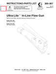
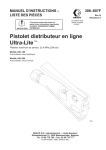
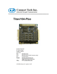
BlueStorm Universal PCI User Manual Contact Information: Connect Tech Inc. 42 Arrow Road Guelph, Ontario, Canada N1K 1S6 Tel: 519-836-1291 (International) 800-426-8979 (Canada & USA) Fax: 519-836-4878 Email: [email protected] [email protected] URL: www.connecttech.com CTIM-00015 revision 8 November, 2007 BlueStorm Installation Guide, Connect Tech Inc. Limited Lifetime Warranty Connect Tech Inc. provides a Lifetime Warranty for all Connect Tech Inc. products. Should this product, in Connect Tech Inc.'s opinion, fail to be in good working order during the warranty period, Connect Tech Inc. will, at its option, repair or replace this product at no charge, provided that the product has not been subjected to abuse, misuse, accident, disaster or non Connect Tech Inc. authorized modification or repair. You may obtain warranty service by delivering this product to an authorized Connect Tech Inc. business partner or to Connect Tech Inc. along with proof of purchase. Product returned to Connect Tech Inc. must be pre-authorized by Connect Tech Inc. with an RMA (Return Material Authorization) number marked on the outside of the package and sent prepaid, insured and packaged for safe shipment. Connect Tech Inc. will return this product by prepaid ground shipment service. The Connect Tech Inc. Lifetime Warranty is defined as the serviceable life of the product. This is defined as the period during which all components are available. Should the product prove to be irreparable, Connect Tech Inc. reserves the right to substitute an equivalent product if available or to retract Life Time Warranty if no replacement is available. The above warranty is the only warranty authorized by Connect Tech Inc. Under no circumstances will Connect Tech Inc. be liable in any way for any damages, including any lost profits, lost savings or other incidental or consequential damages arising out of the use of, or inability to use, such product. Copyright Notice The information contained in this document is subject to change without notice. Connect Tech Inc. shall not be liable for errors contained herein or for incidental consequential damages in connection with the furnishing, performance, or use of this material. This document contains proprietary information that is protected by copyright. All rights are reserved. No part of this document may be photocopied, reproduced, or translated to another language without the prior written consent of Connect Tech, Inc. Copyright 1997 - 2007 by Connect Tech, Inc. Trademark Acknowledgment Connect Tech, Inc. acknowledges all trademarks, registered trademarks and/or copyrights referred to in this document as the property of their respective owners. Not listing all possible trademarks or copyright acknowledgments does not constitute a lack of acknowledgment to the rightful owners of the trademarks and copyrights mentioned in this document. 2 Revision 0.08 BlueStorm Installation Guide, Connect Tech Inc. Table of Contents Limited Lifetime Warranty ..............................................................................................................................2 Copyright Notice..............................................................................................................................................2 Trademark Acknowledgment...........................................................................................................................2 Table of Contents.............................................................................................................................................3 List of Figures ..........................................................................................................3 List of Tables ...........................................................................................................4 Customer Support Overview............................................................................................................................5 Contact Information .........................................................................................................................................5 Introduction......................................................................................................................................................6 Features............................................................................................................................................................6 BlueStorm Installation Overview.....................................................................................................................7 Hardware Configuration ..................................................................................................................................7 Interrupts and Memory Address Selection ...................................................................7 Electrical Interfaces .........................................................................................................................................7 RS-422/485 Electrical Interface..................................................................................7 Full Duplex Mode ......................................................................................................7 Half Duplex Mode .....................................................................................................7 Multi-drop Slave Mode..............................................................................................8 Line Bias/Termination ...............................................................................................8 Jumper Block Diagrams for BlueStorm ...........................................................................................................8 Jumper Configuration for BlueStorm.............................................................................................................11 TxD Control...........................................................................................................12 RxD Control...........................................................................................................12 RxD ± Termination/Bias..........................................................................................12 TxD ± Termination .................................................................................................12 Auto 485................................................................................................................12 Power-On Tri-state (BlueStorm/SP models only) .......................................................13 Connectors and Pinouts..................................................................................................................................13 Hardware Installation.....................................................................................................................................23 Software/Driver Installation...........................................................................................................................23 Specifications.................................................................................................................................................23 Operating Environment ...........................................................................................23 PCI Bus Interface....................................................................................................23 Communications.....................................................................................................23 Baud Rates ...............................................................................................................23 UARTs .....................................................................................................................24 Surge Suppression ..................................................................................................24 Optical Isolation .....................................................................................................24 Dimensions ............................................................................................................24 Certification .....................................................................................................................................25 List of Figures Figure 1: BlueStorm/LP jumper block locations, 2 port models .................................................................... 8 Figure 2: BlueStorm/LP jumper block locations, 4 port models .................................................................... 9 Figure 3: BlueStorm/LP jumper block locations, 8 port models .................................................................... 9 Figure 4: BlueStorm/SP jumper block locations, 8 port models .................................................................. 10 Figure 5: BlueStorm/SP Opto jumper block locations, 4 port models.......................................................... 10 Figure 6: BlueStorm/SP RJ-11 diagram, 8 port models ............................................................................... 11 Figure 7: Jumper configuration examples for 4 port RS-422/485 BlueStorm/LP models............................ 12 Figure 8: Jumper configuration examples for BlueStorm/SP and BlueStorm/SP Opto models ................... 12 Figure 9: Jumper configuration examples for BlueStorm/SP RJ-11 models ................................................ 12 Figure 10: RS-422/485 Wiring Diagrams (BlueStorm/LP and BlueStorm/SP only).................................... 22 Figure 11: RS-422/485 Wiring Diagrams (BlueStorm/SP only) .................................................................. 22 Revision 0.08 3 BlueStorm Installation Guide, Connect Tech Inc. List of Tables Table 1: DB-25 Female Pinouts for BlueStorm/LP (2 port connector) ........................................................ 13 Table 2: HDB-44 Pinouts for BlueStorm/LP (4 port connector) .................................................................. 14 Table 3: VHDCI-68 Female pinouts for BlueStorm/LP (8 port connector) ................................................. 15 Table 4: HDB-78 pinouts for BlueStorm/SP (8 port connector) .................................................................. 17 Table 5: RJ-45 pinouts for BlueStorm/SP Opto (4 port connector).............................................................. 19 Table 6: Pinouts and Control Signals for DB-9 and DB-25 Male connectors (BlueStorm/LP and BlueStorm/SP).............................................................................................................................................. 20 Table 7: Pinouts and Control Signals for DB-9 Male connectors (BlueStorm/SP Opto) ............................. 20 Table 8: RJ-11 Pinouts for BlueStorm/SP RJ-11 (ports 7 and 8 only) ........................................................ 21 Table 9: Pinouts and Control Signals for RJ-11 Connectors (BlueStorm/SP RJ-11 only) ........................... 21 4 Revision 0.08 BlueStorm Installation Guide, Connect Tech Inc. Customer Support Overview If you experience difficulties after reading the manual and/or using the product, contact the Connect Tech reseller from which you purchased the product. In most cases the reseller can help you with product installation and difficulties. In the event that the reseller is unable to resolve your problem, our highly qualified support staff can assist you. Our support section is available 24 hours a day, 7 days a week on our website at: www.connecttech.com/sub/support/support.asp. See the contact information section below for more information on how to contact us directly. Our technical support is always free. Contact Information We offer three ways for you to contact us: Mail/Courier You may contact us by letter at: Connect Tech Inc. Technical Support 42 Arrow Road Guelph, Ontario Canada N1K 1S6 Email/Internet You may contact us through the Internet. Our email and URL addresses on the Internet are: [email protected] [email protected] www.connecttech.com Note: Please go to the Download Zone or the Knowledge Database in the Support Center on the Connect Tech website for product manuals, installation guides, device driver software and technical tips. Submit your technical support questions to our customer support engineers via the Support Center on the Connect Tech website. Telephone/Facsimile Technical Support representatives are ready to answer your call Monday through Friday, from 8:30 a.m. to 5:00 p.m. Eastern Standard Time. Our numbers for calls are: Telephone: 800-426-8979 (North America only) Telephone: 519-836-1291 (Live assistance available 8:30 a.m. to 5:00 p.m. EST, Monday to Friday) Facsimile: 519-836-4878 (on-line 24 hours) Revision 0.08 5 BlueStorm Installation Guide, Connect Tech Inc. Introduction Connect Tech Inc. presents BlueStorm/LP/SP/SP Opto and SP RJ-11. These high-speed multiport communication adapters are designed for Low Profile (LP) and Standard Profile (SP) PCI compatible computers. BlueStorm cards provide you with up to eight high performance serial ports and baud rates up to 1.8432 Mbps that are compatible with any standard serial communications application. BlueStorm cards are fully PCI compliant. Simply install your card into an available PCI slot in your computer and with Plug and Play installation - the hardware setup is complete. BlueStorm cards are an ideal solution for multi-port serial communications in applications such as Point of Sale; Industrial Process Control, Office Automation and Data/Telecommunications. They allow easy attachment of peripherals such as barcode scanners, receipt printers, card readers, testing and monitoring equipment, modems, printers and any other device requiring serial communications. Features • • • • • • • • • Two, four or eight high performance asynchronous serial ports in various RS-232 and/or RS-422/485 electrical interface configurations. Baud rates up to 921.6 Kbps (RS-232) and 1.8432 Mbps (RS-422/485) using PCI UARTs with 64 bytes of TxD/RxD FIFO buffers. Supports three RS-422/485 modes: Full Duplex, Half Duplex, Multi-drop Slave. Each port can be configured independently (baud rate, parity, data and stop bits). DB-9 male fan-out cable (custom cable solutions also offered). Six RJ-11 connectors provide +12 VDC or +5 VDC output on pin 6 with a current limit of 300 mA (BlueStorm/SP RJ-11 model only). Optional multi-strike surge suppression on all signals, all ports (select models only). PCI compliant - with Plug and Play installation. QNX 4.X/6.X, Windows 2000/CE/XP/XPe/XP x64/Server 2003/Server 2003 x64,Vista, VxWorks, Ardence RTX and Linux compatible (contact Connect Tech for most current list) Your BlueStorm product consists of the following components: A BlueStorm adapter An additional low/standard height chassis bracket ( available on LP models only) One of the following; DB-9 fan-out cable, approximately 12 in./30.5 cm long, a DB-9 external I/O box , approximately 4ft./122 cm long, or a DB-25 fan-out cable, approximately 12in./30 cm long (optional) • BlueStorm device drivers and documentation CD • • • 6 Revision 0.08 BlueStorm Installation Guide, Connect Tech Inc. BlueStorm Installation Overview There are three stages to installing your BlueStorm card: 1. Hardware Configuration Interrupts and Memory selection will be set by the host computer’s BIOS and operating system. This section outlines jumper settings and configuration. 2. Hardware Installation Installation involves the physical installation of the BlueStorm into your computer. Please note that you should configure any jumper settings prior to installing the board. 3. Software/Driver Installation Load the appropriate driver for your Operating System, as found on the accompanying CD. Installation guides are also available on the CD to aid you in this process. Hardware Configuration Interrupts and Memory Address Selection All BlueStorm products are PCI cards. Therefore, the host computer’s BIOS will automatically set interrupts and memory addresses when you reboot after installation. Electrical Interfaces RS-422/485 Electrical Interface All BlueStorm adapters (excluding BlueStorm/SP RJ-11) support three modes of RS232/422/485 communication, as outlined below. (See Figure 1 and Figure 2 for jumper block locations.) Full Duplex Mode In this mode, TxD+/- & RxD+/- are being driven to a known level all the time. This mode is typically used in point-to-point situations much like RS-232. It is the default setting. Half Duplex Mode In this mode the TxD+/- line driver is enabled only when data is transmitted and RxD+/- is disabled when data is being transmitted. This mode is typically used in either point-to-point 2wire connections OR in multi-drop 2-wire bus connections. This mode requires software setup in Control Panel – System – Hardware – Device Manager – Ports – CTI PCI UART. Click on Advanced under Port Settings after the driver is installed. (See Multi-drop Slave below) Revision 0.08 7 BlueStorm Installation Guide, Connect Tech Inc. Multi-drop Slave Mode In this mode the TxD+/- line driver is enabled only when data is transmitted and RxD+/- is enabled all the time. This mode is typically used in multi-drop 4-wire connections. This mode requires software setup in Control Panel – System Properties – Hardware - Device Manager – Ports – CTI PCI UART. Click on Advanced under Port Settings. Line Bias/Termination The RS-422/485 transceivers, both transmit and receive are optionally biased to produce a line level mark condition through jumper selectable resistors. These options are typically used in multi-drop 4-wire connections. Jumper Block Diagrams for BlueStorm Figure 1: BlueStorm/LP jumper block locations, 2 port models 8 Revision 0.08 BlueStorm Installation Guide, Connect Tech Inc. Figure 2: BlueStorm/LP jumper block locations, 4 port models Figure 3: BlueStorm/LP jumper block locations, 8 port models Revision 0.08 9 BlueStorm Installation Guide, Connect Tech Inc. Note: Jumper blocks are not installed for ports communicating in RS-232. Female HDB-78 Jx • • • • • • • • • • Jx1 Jx2 Jx3 Jx4 Jx5 JA = Port 1 JB = Port 2 JC = Port 3 JD = Port 4 JE = Port 5 JF = Port 6 JG = Port 7 JH = Port 8 Figure 4: BlueStorm/SP jumper block locations, 8 port models Note: Jumper blocks are not installed for ports communicating in RS-232. Jx • • • • • • • • • • Jx1 Jx2 Jx3 Jx4 Jx5 4 x RJ-45 JA = Port 1 JB = Port 2 JC = Port 3 JD = Port 4 JE = Port 5 JF = Port 6 JG = Port 7 JH = Port 8 Figure 5: BlueStorm/SP Opto jumper block locations, 4 port models 10 Revision 0.08 BlueStorm Installation Guide, Connect Tech Inc. Pin 1 Pin 1 6 x RJ-11 Figure 6: BlueStorm/SP RJ-11 diagram, 8 port model Note: Refer to Table 8 for port 7 and port 8 pinouts. Jumper Configuration for BlueStorm Jumper configurations will vary by model. BlueStorm/LP cards feature the jumper layout listed in Figure 7, while BlueStorm/SP and BlueStorm/SP Opto cards use the jumper layout in Figure 8. Lastly, BlueStorm/SP RJ-11 uses the jumper layout used in Figure 9. Figure 7 demonstrates a common set of jumper configurations for a BlueStorm/LP RS-422/485 card. BlueStorm/LP RS-232 ports do not require jumper configuration. The four RS-422/485 ports are set as follows: Port 1 is set for half duplex, Port 2 is set for half duplex, Port 3 is set for full duplex, and Port 4 is set for multi-drop slave. Figure 8 indicates a common set of jumper configurations for BlueStorm/SP and BlueStorm/SP Opto. The four ports are set as follows: Port 1 is set for RS-232, Port 2 is set for half duplex, Port 3 is set for full duplex, and Port 4 is set for multi-drop slave. Figure 9 illustrates the jumper configurations for selecting +5V power or +12V power. Revision 0.08 11 BlueStorm Installation Guide, Connect Tech Inc. JA JD1 JD2 JD3 JD4 JD5 JC JB JD1 JD2 JD3 JD4 JD5 JD1 JD2 JD3 JD4 JD5 Port 1 JD Port 3 Port 2 TxD control RxD control RxD ± Termination/Bias RxD ± Termination/Bias TxD ± Termination JD1 JD2 JD3 JD4 JD5 Port 4 Figure 7: Jumper configuration example for 4 port RS-422/485 BlueStorm/LP models JA JA0 JA1 JA2 JA3 JA4 JA5 Port 1 JC JB JC0 JC1 JC2 JC3 JC4 JC5 JB0 JB1 JB2 JB3 JB4 JB5 Port 2 JD RS-485 selection TxD control RxD control RxD ± Termination/Bias RxD ± Termination/Bias TxD ± Termination JD0 JD1 JD2 JD3 JD4 JD5 Port 3 Port 4 Figure 8: Jumper configuration example for BlueStorm/SP and BlueStorm/SP Opto models J1 position = +5V power J2 position = +12V power Figure 9: Jumper configuration examples for BlueStorm/SP RJ-11 models TxD Control Install this jumper to enable the RS-485 transmitter only when sending data. This mode is useful for half-duplex operation when only one device is allowed to send data at a time. If the jumper is not installed, the transmitter will always drive the line to an idle state when not sending data. RxD Control Install this jumper to enable the RS-485 receiver only when NOT transmitting data. This is useful for half-duplex operation to prevent the transmitting device from receiving its own data as it sends. If this jumper is not installed, the receiver is always enabled and ready to receive data. RxD ± Termination/Bias Install this pair of jumpers to enable a 150 ohm terminator across the RxD+ and RxD- pins for the corresponding port. A biasing network is also enabled that drives the receiver to an inactive or safe mode. The receiver can still receive data from another device and the biasing helps to prevent the reception of data generated by noise on the transmission line. The two jumpers for RxD termination/bias must be installed and removed as a pair. TxD ± Termination Install this jumper to enable a 150 ohm resistor across the TxD+ and TxD- pins of the corresponding port. Auto 485 (BlueStorm/LP 2 port RS-422/485 models and BlueStorm/SP Opto models only) Install this jumper to tri-state the transmitters of ports configured as RS-485 half duplex or multi-drop slave when the computer boots or is reset. This jumper will be overridden once the operating system is booted by the current driver/software RS-485 mode. The jumper is used to ensure that a port will power-on tri-stated. For example, the RS-485 mode selection in the Windows control panel will override this jumper setting once a port is opened. 12 Revision 0.08 BlueStorm Installation Guide, Connect Tech Inc. Note that Auto 485 is a single jumper. The second site is not in use. See Figure 1 for the location of this jumper. Power-On Tri-state (BlueStorm/SP models only, excludes BlueStorm/SP RJ-11) BlueStorm/SP models offer a power-on tri-state similar to the Auto-485 mode listed above. The BlueStorm/SP implementation will tri-state ports configured as RS-485 full duplex. This is meant to ensure compatibility with our legacy Blue Heat/PCI cards. Jumper J1 controls the power-on tri-state functionality. Install a jumper on the first location of the J1 in order to tri-state Port 1 at power-on, install a jumper on the second position for Port 2, etc. Ports will not come out of tri-state until the driver opens the affected port. Half Duplex and Multi-drop Slave modes require you to select the appropriate mode via software. Please refer to the readme.txt files found in the appropriate directories on the BlueStorm/LP/SP/SP Opto CD. Connectors and Pinouts Table 1: DB-25 Female Pinouts for BlueStorm/LP (2 port connector) Pin No. 1 2 3 4 5 6 7 8 9 10 11 12 13 14 15 16 17 18 19 20 21 22 23 24 25 Port No. 2 1 1 1 1 1 1 1 2 2 2 2 2 2 1 1 2 2 RS-232 Signal SG TXD RXD RTS CTS DSR SG DCD TXD RXD RTS CTS DSR NC NC NC NC NC DTR DTR NC RI RI NC DCD Signal Direction signal gnd. output input output input input signal gnd. input output input output input input no connect no connect no connect no connect no connect output output no connect input input no connect input RS-422/485 Signal SR TXDTXD+ RTSRTS+ CTSSR RXD+ TXDTXD+ RTSRTS+ CTSNC NC NC NC NC RXDRXDNC CTS+ CTS+ NC RXD+ Signal Direction signal ref. output output output output input signal ref. input output output output output input no connect no connect no connect no connect no connect input input no connect input input no connect input Cable CBG002 sends the signals to two DB-9 male connectors. See Table 6 for pinout details. NOTE: This is not the pinout of DB-25 cable CBG007. Revision 0.08 13 BlueStorm Installation Guide, Connect Tech Inc. Table 2: HDB-44 Pinouts for BlueStorm/LP (4 port connector) Pin No. 1 2 3 4 5 6 7 8 9 10 11 12 13 14 15 16 17 18 19 20 21 22 23 24 25 26 27 28 29 30 31 32 33 34 35 36 37 38 39 40 41 42 43 44 Port No. 1 1 1 1 2 2 2 2 3 3 3 3 4 4 4 1 1 2 2 3 3 4 4 4 1 1 1 2 2 2 3 3 3 4 4 4 RS-232 Signal TXD RTS DCD RXD TXD RTS DCD RXD TXD RTS DCD RXD TXD RTS DCD CTS SG NC NC CTS SG NC CTS SG NC NC CTS SG NC RXD DSR DTR RI NC DSR DTR RI NC DSR DTR RI DSR DTR RI Signal Direction output output input input output output input input output output input input output output input input signal gnd. no connect no connect input signal gnd. no connect input signal gnd. no connect no connect input signal gnd. no connect input input output input no connect input output input no connect input output input input output input RS-422/485 Signal TXDRTSRXD+ TXD+ TXDRTSRXD+ TXD+ TXDRTSRXD+ TXD+ TXDRTSRXD+ RTS+ SR NC NC RTS+ SR NC RTS+ SR NC NC RTS+ SR NC TXD+ CTSRXDCTS+ NC CTSRXDCTS+ NC CTSRXDCTS+ CTSRXDCTS+ Signal Direction output output input output output output input output output output input output output output input output signal ref. no connect no connect output signal ref. no connect output signal ref. no connect no connect output signal ref. no connect output input input input no connect input input input no connect input input input input input input Cable CBG003 sends the signals to four DB-9 male connectors. Cable CBG007 sends the signals to four DB-25 connectors. See Table 6 for pinout details. 14 Revision 0.08 BlueStorm Installation Guide, Connect Tech Inc. Table 3: VHDCI-68 Female Pinouts for BlueStorm/LP (8 port connector) Pin No. 1 2 3 4 5 6 7 8 9 10 11 12 13 14 15 16 17 18 19 20 21 22 23 24 25 26 27 28 29 30 31 32 33 34 35 36 37 38 39 40 41 42 43 44 45 46 Port No. 1 1 1 1 1 1 1 1 2 2 2 2 2 2 2 2 1, 2 3, 4 3 3 3 3 3 3 3 3 4 4 4 4 4 4 4 4 5 5 5 5 5 5 5 5 6 6 6 6 RS-232 Signal TXD RI DCD DTR RTS DSR RXD CTS TXD RI DCD DTR RTS DSR RXD CTS SG SG TXD RI DCD DTR RTS DSR RXD CTS TXD RI DCD DTR RTS DSR RXD CTS TXD RI DCD DTR RTS DSR RXD CTS TXD RI DCD DTR Signal Direction output input input output output input input input output input input output output input input input signal gnd. signal gnd. output input input output output input input input output input input output output input input input output input input output output input input input output input input output RS-422/485 Signal TXDCTS+ RXD+ RXDRTSCTSTXD+ RTS+ TXDCTS+ RXD+ RXDRTSCTSTXD+ RTS+ SR SR TXDCTS+ RXD+ RXDRTSCTSTXD+ RTS+ TXDCTS+ RXD+ RXDRTSCTSTXD+ RTS+ TXDCTS+ RXD+ RXDRTSCTSTXD+ RTS+ TXDCTS+ RXD+ RXD- Signal Direction output input input input output input output output output input input input output input output output signal ref. signal ref. output input input input output input output output output input input input output input output output output input input input output input output output output input input input ...Continued on next page Revision 0.08 15 BlueStorm Installation Guide, Connect Tech Inc. Table 3: VHDCI-68 Female Pinouts for BlueStorm/LP (continued) Pin No. 47 48 49 50 51 52 53 54 55 56 57 58 59 60 61 62 63 64 65 66 67 68 Port No. 6 6 6 6 5, 6 7, 8 7 7 7 7 7 7 7 7 8 8 8 8 8 8 8 8 RS-232 Signal RTS DSR RXD CTS SG SG TXD RI DCD DTR RTS DSR RXD CTS TXD RI DCD DTR RTS DSR RXD CTS Signal Direction output input input input signal gnd. signal gnd. output input input output output input input input output input input output output input input input RS-422/485 Signal RTSCTSTXD+ RTS+ SR SR TXDCTS+ RXD+ RXDRTSCTSTXD+ RTS+ TXDCTS+ RXD+ RXDRTSCTSTXD+ RTS+ Signal Direction output input output output signal ref. signal ref. output input input input output input output output output input input input output input output output Cable CBG009 and/or IOBG08BLV1will send the signals to eight DB-9 male connectors. See Table 6 for the DB-9 pinouts. Cable CBG026 will send the signals to eight DB-25 male connectors. See Table 6 for the DB-25 pinout details. 16 Revision 0.08 BlueStorm Installation Guide, Connect Tech Inc. Table 4: HDB-78 Pinouts for BlueStorm/SP (8 port connector) Pin Port RSNo. No. 232 Signal 1 5 RTS 2 5 CTS 3 5 DSR 4 5 RI 5 5 SG 6 6 RTS 7 6 CTS 8 6 DSR 9 6 RI 10 7 RTS 11 7 CTS 12 7 DSR 13 7 RI 14 7 SG 15 8 RTS 16 8 CTS 17 8 DSR 18 8 RI 19 NC 20 NC 21 5 TxD 22 5 RxD 23 5 DTR 24 5 DCD 25 6 SG 26 6 TxD 27 6 RxD 28 6 DTR 29 6 DCD 30 7 TxD 31 7 RxD 32 7 DTR 33 7 DCD 34 SG 35 8 TxD 36 8 RxD 37 8 DTR 38 8 DCD 39 8 SG …Continued on next page Revision 0.08 Signal Direction output input input input signal gnd. output input input input output input input input signal gnd. output input input input no connect no connect output input output input signal gnd. output input output input output input output input signal gnd. output input output input signal gnd. RS-422/48 5 Signal RTS A(-) RTS B(+) CTS A(-) CTS B(+) SR RTS A(-) RTS B(+) CTS A(-) CTS B(+) RTS A(-) RTS B(+) CTS A(-) CTS B(+) SR RTS A(-) RTS B(+) CTS A(-) CTS B(+) NC NC TxD A(-) TxD B(+) RxD A(-) RxD B(+) SR TxD A(-) TxD B(+) RxD A(-) RxD B(+) TxD A(-) TxD B(+) RxD A(-) RxD B(+) NC TxD A(-) TxD B(+) RxD A(-) RxD B(+) SR Signal Direction output output input input signal ref. output output input input output output input input signal ref. output output input input no connect no connect output output input input signal ref. output output input input output output input input no connect output output input input signal ref. 17 BlueStorm Installation Guide, Connect Tech Inc. Table 4: HDB-78 Pinouts for BlueStorm/SP (continued) Pin Port RSNo. No. 232 Signal 40 1 RTS 41 1 CTS 42 1 DSR 43 1 RI 44 1 SG 45 2 RTS 46 2 CTS 47 2 DSR 48 2 RI 49 3 RTS 50 3 CTS 51 3 DSR 52 3 RI 53 3 SG 54 4 RTS 55 4 CTS 56 4 DSR 57 4 RI 58 NC 59 NC 60 1 TxD 61 1 RxD 62 1 DTR 63 1 DCD 64 2 SG 65 2 TxD 66 2 RxD 67 2 DTR 68 2 DCD 69 3 TxD 70 3 RxD 71 3 DTR 72 3 DCD 73 4 SG 74 4 TxD 75 4 RxD 76 4 DTR 77 4 DCD 78 NC Signal Direction output input input input signal gnd. output input input input output input input input signal gnd. output input input input no connect no connect output input output input signal gnd. output input output input output input output input signal gnd. output input output input no connect RS-422/48 5 Signal RTS A(-) RTS B(+) CTS A(-) CTS B(+) SR RTS A(-) RTS B(+) CTS A(-) CTS B(+) RTS A(-) RTS B(+) CTS A(-) CTS B(+) SR RTS A(-) RTS B(+) CTS A(-) CTS B(+) NC NC TxD A(-) TxD B(+) RxD A(-) RxD B(+) SR TxD A(-) TxD B(+) RxD A(-) RxD B(+) TxD A(-) TxD B(+) RxD A(-) RxD B(+) SR TxD A(-) TxD B(+) RxD A(-) RxD B(+) NC Signal Direction output output input input signal ref. output output input input output output input input signal ref. output output input input no connect no connect output output input input signal ref. output output input input output output input input signal ref. output output input input no connect Cable CAG08FXDX and/or the IOBG08DB9V1 will send the signals to eight DB-9 male connectors. See Table 6 for the DB-9 pinouts. Cable CAG08DB25 will send the signals to eight DB-25 connectors. See Table 6 for the DB-25 pinouts. 18 Revision 0.08 BlueStorm Installation Guide, Connect Tech Inc. Table 5: RJ-45 Pinouts for BlueStorm/SP Opto (4 port connector) Pin No. 1 2 3 4 5 6 7 8 9 10 RS-232 Signal N/C N/C RTS SG TxD RxD Gnd CTS N/C N/C RS-422/485 Signal RTS (-) RxD (+) RTS (+) SR TxD (+) RxD (-) Gnd. CTS (+) TxD (-) CTS (-) Direction no connect input output signal gnd output input ground input no connect no connect Direction output input output signal ref. output input ground input output input RJ-45 connector 1 10 Cable CAGRJ4509 will send the signals to eight DB-9 male connectors. See Table 7 for the DB-9 pinouts Revision 0.08 19 BlueStorm Installation Guide, Connect Tech Inc. Table 6: Pinouts and Control Signals for DB-9 and DB-25 Male Connectors (BlueStorm/LP and BlueStorm/SP only) DB-9 1 2 3 4 5 6 7 8 9 Pin # DB-25 8 3 2 20 7 6 4 5 22 Signal DCD RxD TxD DTR SG DSR RTS CTS RI RS-232 Signal Direction input input output output signal gnd. input output input input Signal RxD + TxD + TxD – RxD – SR CTS – RTS – RTS + CTS + DB-9 male RS-422/485 Signal Direction input output output input signal ref. input output output input DB-25 male Table 7: Pinouts and Control Signals for DB-9 Male Connectors (BlueStorm/SP Opto only) Pin No. 1 2 3 4 5 6 7 8 9 RS-232 Signal N/C RxD TxD N/C SG N/C RTS CTS N/C Direction no connect input output no connect signal gnd no connect output input no connect RS-422/485 Signal RxD (+) RxD (-) TxD (+) TxD (-) SR CTS (-) RTS (+) CTS (+) RTS (-) Direction input input output output signal ref. input output input output Male DB-9 Connector 1 5 6 9 Please note that the DB-9 pinouts for BlueStorm/LP and BlueStorm/SP differ from the BlueStorm/SP Opto 20 Revision 0.08 BlueStorm Installation Guide, Connect Tech Inc. Table 8: RJ-11 Pinouts for BlueStorm/SP RJ-11 (ports 7 and 8 only) Pin No. 1 2 3 4 5 6 7 8 9 10 RS-232 DCD DSR RxD RTS TxD CTS DTR RI SG N/C Direction input input input output output input output input signal gnd. no connect 1 2 3 4 5 6 7 8 9 10 P7/P8 Please note that ports 7 and 8 are not accessible through the factory installed bracket. Table 9: Pinouts and Control Signals for RJ-11 Connectors (BlueStorm/SP RJ-11 only) Ports 7 and 8 when a DB-9 cable (part number CAG104K) is attached DB-9 RS-232 Pin No. Signal Direction 1 DCD input 2 RxD input 3 TxD output 4 DTR output 5 SG signal ground 6 DSR input 7 RTS output 8 CTS input 9 RI input RJ-11 Connector Male DB-9 Connector 1 5 6 Ports 1 through 6, which are accessible through the factory installed bracket RJ-11 RS-232 Pin No. Signal Direction 1 RTS output 2 RxD input 3 TxD output 4 DSR input 5 SG Signal/power ground 6 +12 VDC** output or +5 VDC** ** J1 selects +5 VDC, J2 selects +12 VDC 1 6 9 Part #:CAG104K Technical Tip: Please ensure that you terminate the CTS signal if your application does not use them. The common way to do this is to connect CTS to RTS. Failure to do so may result in loss of a performance on your BlueStorm/SP RJ-11 adapter. Revision 0.08 21 BlueStorm Installation Guide, Connect Tech Inc. RS-422/485 2 Wire Diagram BlueStorm/LP/SP Adapter RS-422/485 Peripheral RxD + TxD + TxD + RxD + TxD - RxD - 4 RxD - TxD - 8 RTS + RTS + 9 CTS + CTS + 7 RTS - RTS - CTS - CTS - SR SR 1 2 3 6 5 RS-422/485 4 Wire Diagram BlueStorm/LP/SP Adapter RS-422/485 Peripheral TxD + 2 3 1 RxD + TxD - RxD - RxD + TxD + RxD - TxD - RTS + RTS + 9 CTS + CTS + 7 RTS - RTS - CTS - CTS - SR SR 4 8 6 5 Figure 10: RS-422/485 Wiring Diagrams (BlueStorm/LP and BlueStorm/SP only) RS-422/485 4 Wire Diagram RS-422/485 2 Wire Diagram RS-485/422 Peripheral BlueStorm/SP Opto Adapter 1 3 4 2 7 8 9 6 5 RxD + TxD + TxD + RxD + TxD RxD - TxD - RTS + RTS + CTS + CTS + RTS - 3 CTS - SR SR RxD + RxD - RxD + TxD + 2 RxD - TxD - 7 RTS + RTS + 8 CTS + CTS + 9 RTS - RTS - CTS - CTS - SR SR 1 RTS - CTS - TxD + TxD - 4 RxD - RS-422/485 Peripheral BlueStorm/SP Opto Adapter 6 5 Figure 11: RS-422/485 Wiring Diagrams (BlueStorm/SP Opto only) 22 Revision 0.08 BlueStorm Installation Guide, Connect Tech Inc. Hardware Installation Turn the power off to your computer and open it to expose the expansion slots (consult your system’s documentation for more information about this procedure). Choose an available PCI expansion slot, remove the expansion slot cover and insert the BlueStorm adapter, pushing down gently until the board seats fully in the slot. Secure the BlueStorm card to the computer chassis. Software/Driver Installation BlueStorm provides support for QNX 4.X/6.X, Windows 2000/CE/XP/XPe/XP x64/Server 2003/Server 2003 x64,Vista, VxWorks, Ardence RTX and Linux. For installation guidelines and driver codes, please refer to the appropriate directories on the BlueStorm CD. For further information concerning software installation of BlueStorm products please visit Connect Tech’s Download Zone. If you are interested in a device driver for an operating system not listed please contact the Connect Tech Sales Department. Specifications Operating Environment BlueStorm/LP ■ Storage temperature: -55°C to 125°C ■ Operating temperature: 0°C to 70°C ■ Humidity: 5 to 95% non-condensing BlueStorm/SP, BlueStorm/SP Opto and BlueStorm/SP RJ-11 ■ Storage temperature: -55°C to 105°C ■ Operating temperature: 0°C to 70°C ■ Humidity: 5 to 95% non-condensing PCI Bus Interface BlueStorm/LP 3.3V or 5V PCI bus. Please note that the BlueStorm/LP can ship with low and standard profile brackets. BlueStorm/SP, BlueStorm/SP Opto and BlueStorm/SP RJ-11 3.3V or 5V PCI bus Communications Baud Rates RS-232: 50 bps – 921.6 Kbps RS-422/485: 50 bps – 1.8432 Mbps Custom baud rates are also available; please contact our Sales Department for information. Revision 0.08 23 BlueStorm Installation Guide, Connect Tech Inc. UARTs BlueStorm/LP (2 and 4 port models) ■ 17D152 dual UARTs with 64 byte TxD/RxD FIFO buffers BlueStorm/LP (8 port models) ■ 17D158 octal UARTs with 64 byte TxD/RxD FIFO buffers BlueStorm/SP and BlueStorm/SP RJ-11 (8 port models) ■ 17D158 dual UARTs with 64 byte TxD/RxD FIFO buffers BlueStorm/SP Opto (4 port models) ■ 17D152 dual UARTs with 64 byte TxD/RxD FIFO buffers Surge Suppression BlueStorm/LP/SP/SP RJ-11 (excludes BlueStorm/SP Opto) ■ TransGuardTransient Voltage Suppression, able to withstand multiple strikes on every signal of every port ■ Transient Energy dissipation 0.05 joules on every signal of every port ■ Transient peak current rating 15A on every signal of every port ■ EN61000-4-2/3/4 compatible Optical Isolation BlueStorm/SP Opto ■ 3kV peak to peak on every signal of every port Dimensions BlueStorm/LP Low profile form factor - MD1 compliant BlueStorm/SP Length: Height: 11.991 cm, 4.721 inches 9.652 cm, 3.8 inches BlueStorm/SP Opto Length: 14.702 cm, 5.788 inches Height: 10.605 cm, 4.175 inches BlueStorm/SP RJ-11 Length: 12.129 cm, 4.775 inches Height: 10.668 cm, 4.2 inches 24 Revision 0.08 BlueStorm Installation Guide, Connect Tech Inc. Certification Connect Tech Inc. declares that the product(s) covered by the contents of this manual have been tested and found compliant with the below listed standards as required by the Electromagnetic Compatibility (EMC) Directive for General Immunity Compliance, EN 50 0082.1:1997 EN 55022 Conducted and Radiated emissions CISPR 22 Class A EN 55024 Immunity to Disturbances EN 61000-4-2 EN 61000-4-3 EN 61000-4-4 EN 61000-4-6 The above satisfy the requirements of: USA: FCC Class A 47CFR, Part 2 Canada: ICES-003 Europe: EMC Directive Japan: VCCI Australia/New Zealand: AS/NZS Industry Industrie Canada Canada The above agency conformances were met by independent laboratory testing of Connect Tech Inc. product(s) with shielded cables, with metal hoods, attached to either the terminating connectors or cable assemblies supplied with the product(s). Failure to follow good EMC/EMI compliant cabling practices may produce more emissions or less immunity than were obtained in laboratory measurements. Operation of this equipment in a residential area may cause unacceptable interference to radio and TV reception, requiring the user to take whatever steps necessary to correct the interference. Revision 0.08 25