Download Compaq 279362-002 Laptop User Manual

Transcript
RAID Array 3000 Controller Shelf
Hardware User’s Guide
EK–SMCPQ–UG. C01
Compaq Computer Corporation
Houston, Texas
While Compaq Computer Corporation believes the information included in this manual is correct
as of the date of publication, it is subject to change without notice. Compaq makes no
representations that the interconnection of its products in the manner described in this document
will not infringe existing or future patent rights, nor do the descriptions contained in this
document imply the granting of licenses to make, use, or sell equipment or software in
accordance with the description. No responsibility is assumed for the use or reliability of
firmware on equipment not supplied by Compaq or its affiliated companies. Possession, use, or
copying of the software or firmware described in this documentation is authorized only pursuant
to a valid written license from Compaq, an authorized sublicensor, or the identified licensor.
Commercial Computer Software, Computer Software Documentation and Technical Data for
Commercial Items are licensed to the U.S. Government with Compaq’s standard commercial
license and, when applicable, the rights in DFAR 252.227 7015, “Technical Data-Commercial
Items.”
© 1999 Compaq Computer Corporation.
All rights reserved. Printed in U.S.A.
Compaq, the Compaq logo, DIGITAL, DIGITAL UNIX, DECconnect, HSZ, HSG, StorageWorks,
VMS, OpenVMS Registered in the United States Patent and Trademark Office.
UNIX is a registered trademark in the United States and other countries exclusively through
X/Open Company Ltd. Windows NT is a registered trademark of the Microsoft Corporation. Sun
is a registered trademark of Sun Microsystems, Inc. Hewlett-Packard, TACHYON, and HP-UX
are registered trademarks of the Hewlett-Packard Company. IBM and AIX are registered
trademarks of International Business Machines Corporation. All other trademarks and registered
trademarks are the property of their respective owners.
This equipment has been tested and found to comply with the limits for a Class A digital device,
pursuant to Part 15 of the FCC Rules. These limits are designed to provide reasonable protection
against harmful interference when the equipment is operated in a commercial environment. This
equipment generates, uses and can radiate radio frequency energy and, if not installed and used in
accordance with the manuals, may cause harmful interference to radio communications.
Operation of this equipment in a residential area is likely to cause harmful interference in which
case the user will be required to correct the interference at his own expense. Restrictions apply to
the use of the local-connection port on this series of controllers; failure to observe these
restrictions may result in harmful interference. Always disconnect this port as soon as possible
after completing the setup operation. Any changes or modifications made to this equipment may
void the user's authority to operate the equipment.
Warning!
This is a Class A product. In a domestic environment this product may cause radio interference in
which case the user may be required to take adequate measures.
Achtung!
Dieses ist ein Gerät der Funkstörgrenzwertklasse A. In Wohnbereichen können bei Betrieb dieses
Gerätes Rundfunkstörungen auftreten, in welchen Fällen der Benutzer für entsprechende
Gegenmaßnahmen verantwortlich ist.
Attention!
Ceci est un produit de Classe A. Dans un environnement domestique, ce produit risque
de créer des interférences radioélectriques, il appartiendra alors à l’utilisateur de
prendre les mesures spécifiques appropriées.
JAPAN
USA
This equipment generates, uses, and may emit radio frequency energy. The equipment has been
type tested and found to comply with the limits for a Class A digital device pursuant to Part 15 of
FCC rules, which are designed to provide reasonable protection against such radio frequency
interference. Operation of this equipment in a residential area may cause interference in which
case the user at his own expense will be required to take whatever measures may be required to
correct the interference. Any modifications to this device - unless expressly approved by the
manufacturer - can void the user’s authority to operate this equipment under part 15 of the FCC
rules.
Contents
Revision Record ............................................................................................................................ vii
About This Guide ..........................................................................................................................ix
1
Product Overview
1.1
Product Description ...........................................................................................................1–1
1.2
Shelf Features .....................................................................................................................1–5
1.3
Controller Shelf Enclosure ................................................................................................1–5
1.4
Shelf Cabinet Installation ..................................................................................................1–7
1.5 Shelf Major Components...................................................................................................1–7
1.5.1
RAID Array Controller ...............................................................................................1–7
1.5.2
Device I/O Module ......................................................................................................1–8
1.5.3
Host I/O Module ....................................................................................................... 1–10
1.5.4
Shelf Cooling ............................................................................................................ 1–12
1.5.5
Controller Shelf Power Supplies............................................................................. 1–12
1.5.6
Uninterruptable Power Supply (UPS)..................................................................... 1–13
2
1.6
6-Slot Device Expansion Shelf (Optional) ................................................................... 1–14
1.7
Connecting the RAID Array 3000 Controller Shelf to a Host System....................... 1–14
1.8
Specifications .................................................................................................................. 1–19
RAID Array Controller
2.1
Controller Overview ..........................................................................................................2–1
2.2
Controller Features.............................................................................................................2–3
2.3
Controller Reset and LED Indicators ...............................................................................2–5
2.4
Flexible RAID Set Configuration .....................................................................................2–6
2.5 Performance Enhancements ..............................................................................................2–7
2.5.1
Custom Components ...................................................................................................2–7
2.5.2
Efficient Write and Read Algorithms........................................................................2–7
2.6 RAID Levels Supported.....................................................................................................2–8
2.6.1
RAID 0..........................................................................................................................2–9
2.6.2
RAID 1....................................................................................................................... 2–11
EK–SMCPQ–UG. C01
v
RAID Array 3000 Controller Shelf
2
RAID Array Controller (continued)
2.6.3
2.6.4
2.6.5
2.6.6
2.7
RAID 0+1...................................................................................................................2–11
RAID 4 .......................................................................................................................2–13
RAID 5 .......................................................................................................................2–14
JBOD ..........................................................................................................................2–16
System Parameters...........................................................................................................2–16
2.8 Redundant Operation.......................................................................................................2–16
2.8.1
Initialization...............................................................................................................2–17
2.8.2
Message Passing........................................................................................................2–17
2.8.3
Failover ......................................................................................................................2–17
2.9 Environmental..................................................................................................................2–18
2.9.1
Backup Power Management.....................................................................................2–18
3
Installation and Maintenance
3.1
Installation Guidelines ......................................................................................................3–1
3.2 Installing Shelves in the Cabinet ......................................................................................3–2
3.2.1
Installing Shelf Supports ............................................................................................3–7
3.2.2
Installing UPS Brackets..............................................................................................3–9
3.3 Power and SCSI Cable Connection Procedures ............................................................3–13
3.3.1
SCSI Bus Target Addresses and Termination ........................................................3–14
3.3.2
Cabling a Single Device Expansion Shelf Subsystem ...........................................3–15
3.3.3
Cabling a Two Device Expansion Shelf Subsystem ..............................................3–18
3.3.4
Cabling a Three Device Expansion Shelf Subsystem ............................................3–21
3.3.5
Cabling a Four Device Expansion Shelf Subsystem..............................................3–24
3.4
Controller Shelf Status LEDs .........................................................................................3–27
3.5
Controller LEDs...............................................................................................................3–28
3.6 Replacing Components (FRU’s) ....................................................................................3–28
3.6.1
Replacing a Host or Device I/O SBB ......................................................................3–30
3.6.2
Replacing a Power Supply SBB...............................................................................3–31
3.6.3
Replacing the RAID Controller ...............................................................................3–32
3.6.4
Replacing the UPS ....................................................................................................3–33
3.6.5
Replacing a Blower ...................................................................................................3–33
3.6.6
Replacing the Controller Memory Cache Modules ...............................................3–35
4
Second Controller Option
4.1
Introduction ........................................................................................................................4–1
4.2 Install Firmware Upgrade .................................................................................................4–2
4.2.2
Save Existing Configuration ......................................................................................4–3
4.2.3
Install Two SIMMs .....................................................................................................4–5
4.3 Install New Controller .......................................................................................................4–6
4.3.1
Restoring Configuration .............................................................................................4–7
4.4
vi
Configuring a Dual Controller Installation for a Single Serial Port..............................4–9
EK–SMCPQ–UG. C01
Contents
Figures
1–1 RAID Array 3000 Controller Shelf ..................................................................................1–2
1–2 RAID Array 3000 6-Slot Device Expansion Shelf..........................................................1–3
1–3 Controller Shelf Major Components ................................................................................1–6
1–4 RAID Array Controller......................................................................................................1–7
1–5 Device I/O Module.............................................................................................................1–9
1–6 Device I/O Module Blower Status LEDs ...................................................................... 1–10
1–7 Host I/O Module.............................................................................................................. 1–11
1–8 Power Supply................................................................................................................... 1–13
1–9 Single Host, Single Adapter, with One Active Controller........................................... 1–15
1–10 Single Host, Single Adapter, with Two Active Controllers ........................................ 1–16
1–11 Single Host, Dual Adapter, Two Ports, with Two Active Controller ......................... 1–17
1–12 Dual Host, Single Adapter, with One Active Controller per Host.............................. 1–18
2–1 RAID Array 3000 Single Controller Block Diagram......................................................2–2
2–2 Bridging the Gap Between the Host and the Device Expansion Shelf ..........................2–3
2–3 Logical Units Created from Storagesets, Partitions, and Disk Drives ..........................2–4
2–4 Controller Front Panel .......................................................................................................2–6
2–5 RAID 0 Write .................................................................................................................. 2–10
2–6 Diagram of a RAID 1 Write ........................................................................................... 2–11
2–7 Diagram of a RAID 0+1 Write....................................................................................... 2–12
2–8 Diagram of a RAID 4 Write ........................................................................................... 2–13
2–9 Diagram of a RAID 5 Write ........................................................................................... 2–15
3–1 Recommended Single Expansion Shelf Installation ......................................................3–3
3–2 Recommended Controller Shelf Installation (Two Expansion Shelves).......................3–4
3–3 Recommended Controller Shelf Installation (Three Expansion Shelves) ....................3–5
3–4 Recommended Controller Shelf Installation (Four Expansion Shelves) ......................3–6
3–5 RETMA Cabinet Shelf Supports.......................................................................................3–9
3–6 UPS Rack-mount Bracket Assemblies .......................................................................... 3–11
3–7 UPS Bracket RETMA and Metric Hole Locations (Front) ......................................... 3–11
3–8 UPS Bracket RETMA and Metric Mounting Hole Locations (Rear)......................... 3–12
3–9 Controller/Single Device Expansion Shelf Cabling Diagram..................................... 3–16
3–10 AC Power Wiring Diagram ............................................................................................ 3–17
3–11 Controller/Two Device Expansion Shelf Cabling Diagram........................................ 3–19
3–12 Controller/Three Device Expansion Shelf Cabling Diagram...................................... 3–22
3–13 Controller/Four Device Expansion Shelf Cabling Diagram........................................ 3–25
3–14 Shelf Status LEDs ........................................................................................................... 3–27
EK–SMCPQ–UG. C01
vii
RAID Array 3000 Controller Shelf
Figures (continued)
3–15 Controller Shelf Field Replaceable Units......................................................................3–29
3–16 Replacing the Host I/O SBB ...........................................................................................3–30
3–17 Removing the Controller from the Shelf .......................................................................3–32
3–18 Replacing a Blower Assembly........................................................................................3–34
3–19 Controller Cache Modules ..............................................................................................3–36
3–20 Release Locking Clips.....................................................................................................3–36
3–21 Remove Installed SIMM Modules .................................................................................3–37
3–22 Install Replacement Modules .........................................................................................3–38
3–23 Pivot Module Down to Secure........................................................................................3–38
4–1 Update Firmware Command.............................................................................................4–2
4–2 Firmware Update Dialog Box...........................................................................................4–3
4–3 Saving the Existing Configuration ...................................................................................4–4
4–4 Saved Configuration ..........................................................................................................4–4
4–5 Insert Module into SIMM Connector...............................................................................4–5
4–6 Pivot Module Down to Seat ..............................................................................................4–5
4–7 Remove Controller from Top Slot....................................................................................4–6
4–8 Restoring Configuration to New Controller ....................................................................4–7
4–9 Restored Configuration Example .....................................................................................4–8
Tables
1–1 RAID Array 3000 Part Numbers and Model Descriptions ............................................1–4
1–2 Controller Shelf Technical Specifications.....................................................................1–15
1–3 Controller Shelf Power and Physical Specifications ....................................................1–17
2–1 LED/Reset Switch Interface .............................................................................................2–5
2–2 RAID Levels Supported ....................................................................................................2–8
2–3 Shelf RAID Set Restrictions .............................................................................................2–9
2–4 RAID 0+1 Example .........................................................................................................2–12
2–5 Response to Various AC Power Conditions ..................................................................2–18
3–1 Shelf Support Mounting Kits and Installation Guides ...................................................3–7
3–2 RETMA Cabinet Shelf Support Parts List.......................................................................3–7
3–3 UPS Rack-mount Bracket Mounting Hardware List ....................................................3–10
3–4 Controller Shelf Field Replaceable Units......................................................................3–29
viii
EK–SMCPQ–UG. C01
Revision Record
This Revision Record provides a concise publication history of this guide. It lists the
revision levels, release dates, and reasons for the revisions.
The following revision history lists all revisions of this publication and their
effective dates. The publication part number is included in the Revision Level
column, with the last entry denoting the latest revision. This publication supports
the StorageWorks RAID Array 3000 Controller Shelf.
Revision Level
Date
Summary of Changes
EK–SMCPQ–UG. A01
May 1998
Original release.
EK–SMCPQ–UG. B01
July 1998
Adds RETMA cabinet
shelf support installation
procedures.
EK–SMCPQ–UG. C01
July 1999
Adds Shelf-to-Host
connection diagrams to
Chapter 1 and dual
controller configuration
procedure to Chapter 4.
EK–SMCPQ–UG. C01
ix
About This Guide
This section identifies the audience of this guide and describes the contents (chapter-bychapter) and structure. In addition, this section includes a list of associated documents
and the conventions used in this guide.
Intended Audience
This guide is intended for installers and operators of the RAID Array 3000
Controller Shelf. Installing the shelf requires a general understanding of basic
SCSI terminology and product installation procedures.
Document Structure
This guide contains the following chapters:
Chapter 1: Product Overview
Product Overview provides an overview and a physical hardware description of
the RAID Array 3000 controller shelf. It includes the major features, a brief
description of the major components, a series of controller shelf-to-host
connection diagrams, and the specifications for the shelf.
Chapter 2: RAID Array Controller
RAID Array Controller describes the major features and characteristics of the
controller in the RAID Array 3000. It also lists the RAID levels supported by the
subsystem and a brief description of each level. Redundant operation and
environmental considerations (i.e. backup power management, voltages, and
temperature) are covered at the end of the chapter.
Chapter 3: Installation and Maintenance
Installation and Maintenance recommends how to install the controller and
device expansion shelves in a rackmount RETMA or metric cabinet. The
information covers both single and multiple device expansion shelf installations.
The chapter also describes how to interpret the status and power LEDs on the
front panel, how to replace a Field Replaceable Unit (FRU), and how to add or
replace a SIMM module in the RAID controller.
EK–SMCPQ–UG. C01
xi
RAID Array 3000 Controller Shelf
Chapter 4: Second Controller Option
Second Controller Option describes how to install a second (redundant) RAID
controller in the shelf for redundancy. It also contains a dual controller
installation procedure for a single serial port.
Associated Documents
In addition to this guide, refer to the following documentation to properly install
and setup your specific subsystem configuration:
Table 1 Associated Documents
xii
Document Title
Order Number
StorageWorks RAID Array 3000 Configuration and
Maintenance Guide
EK–SMCS2–UG
7 Device, 16-Bit SBB Shelf (BA356-S Series) User’s Guide
EK-BA356-UG
StorageWorks SBB Shelf I/O Modules User’s Guide
EK-SBBIO-UG
RAID Array 3000 Getting Started for Windows NT-Intel
Installation Guide
AA-RACZA-TE
RAID Array 3000 Getting Started for Windows NT-Alpha
Installation Guide
AA-RACUA-TE
RAID Array 3000 Storage Subsystem Second Controller
Option Installation Guide
EK-SM3KC-IG
Command Console 2.1 for RAID Array 3000, User’s Guide
AA-RBF2B-TE
RETMA Shelf Rail Kit Installation Guide
EK-35XRB-IG
RETMA Bracket Installation Guide
ER-PCBAR-AA
EK–SMCPQ–UG. C01
About This Guide
Conventions
This guide uses the following documentation conventions:
Table 2 Style Conventions
Style
Meaning
plain monospace type
Text
boldface type
For the first instance of terms being defined in
text, or both.
italic type
For emphasis, manual titles, chapter
summaries, keyboard key names.
Table 3 Nomenclature Convention
RAID Advisory Board Description
RAID Array 3000 Usage
RAID 0
STRIPset
RAID 1
MIRRORset
RAID 0+1
STRIPED MIRRORset
RAID 4
STRIPED with a Fixed parity drive
RAID 5
STRIPED with a Floating parity drive
EK–SMCPQ–UG. C01
xiii
RAID Array 3000 Controller Shelf
Support and Services
Who to contact in the Americas
Information and Product Questions:
Installation Support:
Local Sales Office / StorageWorks Hotline
1-800-786-7967
Contact the COMPAQ Distributor where the
Storage Solution was Purchased / Local
Compaq Sales Office.
Multivendor Customer Service (MCS):
Installation
Contact the Compaq Customer Support Center
(CSC).
Warranty
Contact the Compaq Customer Support Center
(CSC) for warranty service after solution is
installed and operating.
Remedial
Contact the Compaq Customer Support Center
(CSC) Note: A Service Contract is
recommended when the equipment is out of
warranty. Contact the local Compaq Sales
Office. Customer Support Center (CSC)
1 800-354-9000
Who to contact in Europe
Information and Product Questions: Contact the Compaq Distributor or reseller
Installation Support and Installation: Contact the Compaq Distributor or reseller from
whom the Storage Solution was purchased.
For Warranty Service
See the Warranty Card packaged with the
product.
For Remedial Service
Contact the Compaq Distributor or reseller from
whom the Storage Solution was purchased.
Note: A Service Contract is recommended
when the equipment is out of warranty.
Who to contact in Asia Pacific
For all services, contact the Compaq Distributor or reseller from whom the
equipment was purchased
xiv
EK–SMCPQ–UG. C01
1
Product Overview
This chapter provides an overall description of the RAID Array 3000 Controller Shelf and
its components. A series of cabling diagrams showing how to connect the Controller
Shelf to a host system and a list of technical and environmental specifications is also
included at the end of the chapter.
NOTE
This guide is the Hardware User’s Guide. For
configuration information, refer to the Getting
Started RAID Array 3000 for Windows NT – Intel
Installation Guide and the StorageWorks Command Console (SWCC) 2.1 User’s Guide.
1.1
Product Description
The RAID Array 3000 Controller Shelf (Figure 1–1) is a rackmount storage system containing the basic components required to manage a storage array with
two 16-bit, differential, UltraSCSI bus host interfaces. The devices, referred to as
StorageWorks Building Blocks or SBBs, are disk drives from the StorageWorks
family of storage devices. The release note that accompanies the storage system
lists the software solutions and disk drives that are supported.
The Controller Shelf is connected to one or multiple (up to four) 6-slot Device
Expansion Shelves (shown in Figure 1–2) to form the complete RAID Array
3000 storage system. The expansion shelf is offered as an option with a minimum of one shelf required. It contains six SBB slots for the disk drives, two
power supplies, and a personality I/O module that connects the SCSI interface
with the controller shelf. The Device Expansion Shelf is supported by its own
user’s guide (Part No.: EK–BA356–UG) which must be used in conjunction with
this document to properly install and configure your storage system.
EK–SMCPQ–UG. C01
1–1
RAID Array 3000 Controller Shelf
NOTE
The Device Expansion Shelf (DS-SWXRA-GN)
must have a revision level of B01 (or higher) to
operate with the RAID Array 3000 Controller Shelf.
Also, the Personality I/O module supplied with the
shelf (part no. 70-33067-02) must have a minimum revision level of H01 or higher.
The Controller Shelf and the accompanying Device Expansion Shelves are installed in a standard RETMA or metric rackmount cabinet design. The Device
Expansion Shelves are typically mounted directly above the Controller Shelf in
the cabinet. Each shelf is supplied with a bracket mounting kit to secure the unit
into the desired cabinet design. The bracket kit for a metric cabinet is optional
and must be ordered separately.
Figure 1–1 RAID Array 3000 Controller Shelf
SHR-1034
1–2
EK–SMCPQ–UG. C01
Chapter 1. Product Overview
Figure 1–2 RAID Array 3000 6-Slot Device Expansion Shelf (Optional)
SHR-1091
A battery-backup subsystem is included with the Controller Shelf in the form of
a rackmount UPS (Uninterruptable Power Supply). In case of a power failure, the
UPS provides temporary power to the storage system while it flushes its cache
contents to disks. The UPS is normally installed in the lowest available slot in
the cabinet.
CAUTION
The UPS is sized to perform this function for the
Controller and Device Expansion Shelves only. No
other electrical devices should be plugged into the
UPS.
As an option, a second RAID controller module can be added for redundancy.
The second controller operates in conjunction with the installed controller to
protect data in case of a malfunction in the primary unit. The optional controller
is installed directly below the primary controller in the center of the shelf.
The RAID Array 3000 Controller Shelf enclosure and its associated options are
listed and described in Table 1–1.
EK–SMCPQ–UG. C01
1–3
RAID Array 3000 Controller Shelf
Table 1–1 Controller Shelf Part Numbers and Model Descriptions
DIGITAL Part No.
DS-SWXRA-GH
DS-SWXRA-GK
DS-SWXRA-GN
DS-HSZ22-AA
1–4
Item Description
RA3000 UltraSCSI Rackmount Controller/Shelf with one
controller, 120 V, which Includes:
One BA356 type shelf
One HSZ22 RAID controller with 16 MB of cache
Two 180 Watt power supply SBBs, two dual-port, differential, Ultra Wide, Host I/O modules
One dual-channel, wide, single-ended device I/O module
One 1000 Watt UPS with rackmount bracket
One five meter host SCSI cable
Two 9-pin serial controller cables
Two Trilink SCSI cable adapters
One gray C13-to-125 V power cord
One black C13-to-125 V power cord
One Controller Shelf rackmount kit
User documentation.
Requires: Solutions Software Kit for platform, host
adapter, and disks.
Options: Second HSZ22-AA controller and cache memory
upgrade.
RA3000 UltraSCSI Rackmount Controller/Shelf with one
controller, 230 V, which includes:
Except for power cord (DS-SWXRA-GK includes one
black C13-to-230 V), same as DS-SWXRA-GH above.
RA3000 UltraSCSI Rackmount 6-Slot Storage Expansion
Shelf which includes:
16-bit shelf assembly, two 180 Watt power supply SBBs,
16-bit Personality I/O assembly, shelf rack mounting kit,
power cords, user documentation.
RA3000 Second Controller Option which includes:
DS-HSZ22-AA SCSI controller, three 16-MB SIMM modules, 0.8 m adapter-to-SCSI-3 cable, 5 m SCSI cable, 9pin serial cable, user documentation
EK–SMCPQ–UG. C01
Chapter 1. Product Overview
1.2
Shelf Features
The RAID 3000 Controller Shelf is equipped with a dual-channel RAID controller that supports all of the UltraSCSI bus features.
The major features of the controller shelf are:
• One dual-channel RAID array controller
• Second controller option for redundancy
• Memory cache expansion option for the controller
• Redundant power provided by two universal ac input power supplies (50/60
Hz, 100 to 240 V ac)
• Dual two-speed blowers for shelf cooling
• Cache backup provided by an external Uninterruptable Power Supply (UPS)
• Controls from one-to-four 6-slot Device Expansion Shelves for a total of 24
UltraSCSI devices
• Can be installed in a RETMA or metric style rackmount cabinets
1.3
Controller Shelf Enclosure
The Controller Shelf is housed in an rack-mount enclosure. It has two power
supplies, a single RAID Array controller, an empty slot for a second (redundant)
controller, two host I/O assemblies, and a dual-bus device I/O assembly. Two
blowers located at the back of the enclosure cool the shelf.
An internal backplane assembly connects the RAID controller and the power and
host I/O SBBs. The backplane contains five connectors which provide the interface between the Shelf SBBs and the controller. Two 300-pin connectors located
in the center of the backplane provide the controller interface. The backplane
connection to the blowers is made through two separate 9-pin female connectors,
one for each blower.
The backplane also contains a complement of circuit components that provide
SCSI bus termination, blower fail/safe circuits, UPS power sense circuit, shelf
status and dc power monitoring, and a speaker alarm circuit with an operator
controlled alarm disable switch. The outputs of the shelf status and dc power
monitoring circuits are connected to two LED indicators on the front panel of the
shelf to notify the operator during a malfunction. The alarm disable switch allows the operator to turn off the audible alarm if desired.
EK–SMCPQ–UG. C01
1–5
RAID Array 3000 Controller Shelf
Figure 1–3 shows the major components in the controller shelf. Its characteristics
are outlined below.
• An easily removable, two channel, resident RAID Array controller and an adjacent empty slot for a second (redundant) controller (optional)
• There are two 68-pin VHDCI female SCSI connectors on the front panel of the
device I/O assembly which interconnect the RAID controller to the SCSI
buses in each storage shelf. SCSI connections to multiple Device Expansion
Shelves are made using Trilink adapters
• The front of the shelf contains two LEDs that monitor the status of the shelf
and the shelf dc power supplies
• The front of the shelf has a toggle switch that allows the operator to disable
the shelf alarm during an error condition
• The shelf host I/O assemblies each contain two 68-pin VHDCI female SCSI
connectors that interconnect the host systems to the RAID controller
• Each host I/O assembly contain a 9-pin serial port connector (for controller
configuration) and a 9-pin UPS monitor connector
• Two dc power supplies (one redundant) that power the shelf components
• The shelf contains two high-speed, plug-in blowers for shelf cooling
Figure 1–3 Controller Shelf Major Components
B low er s
D C P ow er
Su pp lie s
R AID
C o ntr oller
B la nk
Pa ne l
H ost 0
I/O M od ule
H o st 1
I/ O Mo du le
D ev ice I /O
M od ule
S H R-10 51
1–6
EK–SMCPQ–UG. C01
Chapter 1. Product Overview
1.4
Shelf Cabinet Installation
The Controller Shelf can be mounted in a StorageWorks metric or RETMA style
cabinet. You must install the appropriate shelf rail kit hardware to properly
mount the shelf in the cabinet. The RETMA rail kit is supplied with the shelf and
contains the installation guide which describes the installation procedure. The
rail kit for a metric cabinet is optional.
The commercial UPS supplied with the Controller Shelf is installed in the cabinet using a special mounting bracket designed to accommodate either a metric or
RETMA style cabinet. The bracket has two sets of mounting holes at each end
which allows its installation into either cabinet.
1.5
Shelf Major Components
The major components in the controller shelf (see Figure 1–3) include:
• Dual-channel RAID array controller (a second redundant controller is optional)
• A 16-bit, device I/O module with the SCSI bus isolator/converter circuitry
• Two 16-bit, host I/O modules that interface the host(s) to the shelf controller
• Two universal 180 W, 50/60 Hz, 120 or 240 Vac power supplies
• Two dual-speed blowers to cool shelf components
1.5.1 RAID Array Controller
The RAID controller (Figure 1–4) contains two Wide/UltraSCSI/differential host
channels and two Wide/UltraSCSI/Single-Ended disk channels. In dual-controller
configurations, the controllers support fully automatic and smooth controller
failover in the event of a RAID controller fault.
Figure 1–4 RAID Array 3000 Controller
Cache Memory
Modules
SHR-1048
EK–SMCPQ–UG. C01
1–7
RAID Array 3000 Controller Shelf
The controller supports one (for a single controller) or two (for dual-controllers)
standard 72-pin cache SIMMs of up to 64 MB. In a dual-controller setup, both
controllers must have identical cache configurations and the total usable cache
(per controller) will be half the amount installed due to mirroring. Thus, in a single controller setup the maximum usable cache is 128 MB while a redundant
setup has a maximum usable cache of 64 MB (per controller).
The RAID Array 3000 controller contains the following features:
•
Single PCB form factor for inclusion in the shelf
•
Support for dual hot-swap controller operation
•
Dual differential Ultra-Wide SCSI host channels
•
Dual single-ended Ultra-Wide SCSI disk channels
•
RAID level 0, 1, 0+1, 4, 5, and JBOD support
•
Voltage/temperature monitoring and support
•
Cluster support for specific operating systems
•
32 Logical Units (LUNs) per host channel (some operating systems may be
limited to 8)
•
Support for spare disks
•
UPS backed write caching
•
Per LUN write cache/write back selection
•
Configuration/Maintenance via serial or host SCSI channel using (SWCC)
StorageWorks Command Console (refer to the operating system platform kit
for details).
•
Update of firmware via host channel
1.5.2 Device I/O Module
The device I/O module (Figure 1–5) provides the electrical interface between the
RAID controller and the device buses. The module resides in the far right slot of
the Shelf and has the following features:
1–8
•
Ability to electrically isolate the controller shelf and the device SCSI buses
•
Single channel, single shelf, single-ended bus operation
•
Single channel, single-ended bus operation for two Device Expansion
Shelves using a Trilink adapter
•
External 16-bit data bus connections
•
Switch selectable 16-bit, 8-bit, or no SCSI bus termination
EK–SMCPQ–UG. C01
Chapter 1. Product Overview
•
Two-speed blower operation
•
SBB shelf blower control to include error detection, reporting, and automatic
corrective action
Figure 1–5 Device I/O Module
Upper
Mounting
Tab
Device Port 0
Connector
Device Port 1
Connector
Lower
Mounting
Tab
SHR-1045
The dual-channel device I/O module has two 68-pin VHDCI female connectors
mounted on the front panel (see Figure 1–5). The upper connector is the “device
port 0” connector. The lower connector is the “device port 1” connector.
The device I/O module top and bottom guides properly align the module in the
shelf and with the backplane connector at the back of the shelf. When you install
the module the two-spring steel mounting tabs expand and engage the shelf. The
combination of the mounting tabs and the backplane connector ensures that the
module is firmly seated.
The front edge of the internal circuit board in the device I/O module contains
two-blower status LEDs (see Figure 1–6). Under normal operating conditions,
the LEDs are ON. When there is a blower error or an over-temperature condition,
they are FLASHING. The upper LED displays the status of the left blower and
the lower LED displays the status of the right blower. The blowers cool the device I/O module by drawing air in through the slots in the front and exhausting it
out the rear of the shelf. Refer to the StorageWorks SBB Shelf I/O Module
User’s Guide (part no. EK-SBBIO-UG) supplied with the Device Expansion Shelf
for a description of the blower status LEDs when troubleshooting a shelf-cooling
problem.
EK–SMCPQ–UG. C01
1–9
RAID Array 3000 Controller Shelf
Figure 1–6 Device I/O Module Blower Status LEDs
Left
Blower
LED
SCSI Bus
Address Switch S3
(Not Used)
Right
Blower
LED
SCSI Bus
Termination
Switch S4
SHR-1046
NOTE
The SCSI bus address switch on the Controller
Shelf device I/O module does not control the target addresses of the SBB slots in the Device Expansion Shelves. This switch has been electrically
disabled by design. Refer to the StorageWorks
SBB Shelf I/O Module User’s Guide supplied with
the Device Expansion Shelf for a description of
how to set the SCSI IDs in each shelf.
SCSI bus termination switch S4 configures the SCSI bus termination of the Device Expansion Shelves in the RAID Array 3000 storage system. The proper settings for S4 are included in the cabling procedures in Chapter 3 of this guide.
1.5.3 Host I/O Module
The Controller Shelf contains two identical Host I/O modules (see Figure 1–7).
The module located directly to the left of the device I/O module is designated as
H1 and the module in the adjacent slot as H0. The host I/O module provides the
interface between the host bus and the controller(s) in the shelf.
1–10
EK–SMCPQ–UG. C01
Chapter 1. Product Overview
Figure 1–7 Host I/O Module
Host Out
Host In
CTR
UPS
SHR-1036
The front panel of the host I/O module contains two 68-pin VHDCI SCSI connectors and two 9-pin D connectors. The SCSI connectors provide the SCSI bus
connections between the adapter in the host system and the controller(s) in the
Shelf. One of the 9-pin D connectors interfaces the UPS status signals to the
controller. The other provides a serial connection between its respective controller, the Shelf, and the SWCC configuration/maintenance PC.
The high-density SCSI connectors on the Host I/O module are designated Host In
(bottom connector) and Host Out (top connector). Host In provides the SCSI
connection for a one-to-four expansion shelf cabinet installation. Cable connections to multiple storage shelves are made through Trilink adapters.
In addition to the front panel connectors, the Host I/O module contains three passive differential SCSI bus terminators that terminate the SCSI bus from the host
system. Termination is automatically disabled when a cable is connected to the
Host Out connector. The UPS serial connector on the host I/O module (designated CTR 0 and CTR 1) provides shelf status information to the UPS.
NOTE
If you have only one SCSI cable connection to the
host I/O module, you must connect the cable to
the Host In connector. Do not use any external
bus termination. The Host Out connector on the
module is used for mid-bus connections in a multiple-host system configuration.
EK–SMCPQ–UG. C01
1–11
RAID Array 3000 Controller Shelf
1.5.4 Shelf Cooling
The device I/O module ensures that the SBBs and Controller Shelf are at the
proper operating temperature by monitoring the operational status of the blowers
and sensing the ambient air temperature.
The two dual-speed blowers cool all the shelf components by drawing ambient
air in through the front of the SBBs and exhausting it out the rear of the Controller Shelf. The blowers normally operate at low speed. Reduction of the airflow through the shelf or an increase in the ambient temperature may result in
overheating causing component failure or data corruption.
The device I/O module ambient temperature circuitry monitors the air flowing
through the module. If the ambient temperature exceeds 32ºC + 2º C, the circuitry:
•
Turns on both blower LEDs
•
Causes both blowers to switch to the high-speed mode to increase air flow
through the shelf
When the I/O module circuitry detects a blower that is not operating or not operating at the correct RPM, this circuitry:
•
Turns ON a LED on the I/O module front panel that identifies the defective
blower
•
Causes the operational blower to switch to the high-speed mode to increase
air flow through the shelf, thereby maintaining the proper operating environment
NOTE
The
also
they
they
Controller Shelf power supply status LEDs
display blower error conditions. However,
do not identify the defective blower, nor do
report ambient air temperature faults.
1.5.5 Controller Shelf Power Supplies
The Controller Shelf has two interchangeable, air-cooled, 180 watt AC power
supply SBBs (see Figure 1–8) located at the left two SBB slots of the shelf. The
power supplies provide redundant power if one of the units should malfunction.
Each supply provides +5 and +12 Vdc to power the RAID controller(s), the host
I/O modules, the device I/O module, and the blowers. The first power supply
from the left edge of the shelf is designated as "A" and the second as "B". The
SBB front panel has an ac input power receptacle, a power supply status LED,
and a shelf status LED.
1–12
EK–SMCPQ–UG. C01
Chapter 1. Product Overview
Figure 1–8 Power Supply
SHR-1034
1.5.6 Uninterruptable Power Supply (UPS)
The primary function of the UPS is to keep the entire storage system powered-up
to enable the controller(s) to flush cache to disks. The UPS also protects the storage system from problems associated with poor quality AC power or a complete
loss of AC power. The UPS is normally mounted in a lower shelf slot in the
cabinet using a custom set of mounting brackets.
The major features of the UPS include Battery Management Technology (doubles battery life and speeds recharge time), hot-swap batteries to simplify service, voltage regulation, power control which enables scheduled shutdowns and
maximized run time, and network surge protection.
The front panel display has user controls (LEDs and control buttons) and the rear
panel contains an RS-232 COMM port which provides UPS status to the electronics in the Controller Shelf. The rear panel also contains the network surge
protector, and four power receptacles. An audible alarm is activated when input
power fails, as a low battery warning, or whenever the UPS is in need of servicing. The front panel control switches are used to set the output voltage level and
battery low-warning option.
The UPS automatically recharges its battery when power is returned following a
power failure. Recharge time is less than four hours depending on the energy requirements of your load and the length of the power outage.
Its own installation, operation, and service manual support the UPS. The manual
describes the UPS in detail and is part of the documentation set enclosed with
your storage system.
EK–SMCPQ–UG. C01
1–13
RAID Array 3000 Controller Shelf
1.6
6-Slot Device Expansion Shelf (Optional)
NOTE
The Device Expansion Shelf (DS-SWXRA-GN)
must have a revision level of B01 (or higher) to
operate with the RAID Array 3000 Controller Shelf.
Also, the Personality I/O module supplied with the
shelf (part no. 70-33067-02) must have a minimum revision level of H01 or higher.
The RAID Array 3000 Controller Shelf is designed to operate with the StorageWorks BA356-S Series Device Expansion Shelf (shown in Figure 1–2. The Device Expansion Shelf is a rackmount enclosure that houses the storage devices
for your storage system installation. The Controller Shelf can be connected to
one, or up to four Device Expansion Shelves giving the storage system a maximum capacity of 24 storage devices.
The Device Expansion Shelf is equipped with two dc power supplies, a personality I/O module that provides the UltraSCSI bus interface, and six empty slots for
storage device SBBs. The user’s guide for the Device Expansion Shelf is packaged with the unit and must be used with this document to properly install and
configure the RAID Array 3000 Controller Shelf.
1.7
Connecting the RA3000 Controller Shelf to a Host System
This section illustrates how to connect four possible Controller Shelf/Host configurations. The configurations are:
1–14
•
Single host, single adapter, with one active controller
•
Single host, single adapter, with two active controllers
•
Single host, dual adapter, two port with two active controllers
•
Dual host, single adapter, with one active controller per host
EK–SMCPQ–UG. C01
Chapter 1. Product Overview
Figure 1–9 Single Host, Single Adapter, with One Active Controller
Host
System
Host
Adapter
SHR-1316
1
BA356 Device Expansion Shelves
2
RAID Array 3000 Controller Shelf
3
SCSI Cable BN37A-05 (host adapter connection made using Technology
Adapter cable BN38E-OB, not shown)
4
Host In Connector on H0 I/O Module
5
Host-In Connector to H1 I/O Module (not used in this configuration)
6
SCSI Cables BN37A-OE (2) for Device I/O Module 0
7
SCSI Cables BN37A-OE (2) for Device I/O Module 1
EK–SMCPQ–UG. C01
1–15
RAID Array 3000 Controller Shelf
Figure 1–10 Single Host, Single Adapter, with Two Active Controllers
2
Host
System
Host
Adapter
SHR-1317
1
BA356 Device Expansion Shelves
2
Host In Connector on H0 I/O Module
3
RAID Array 3000 Controller Shelf
4
SCSI Cable BN37A-05 (host adapter connection made using Technology
Adapter cable BN38E-OB, not shown)
5
SCSI Cable BN37A-OE combining Host Modules H0 and H1
6
Host In Connector on H0 I/O Module
7
Host In Connector on H1 I/O Module
8
H1 Host I/O Module Host-Out Connector (not used in this configuration)
9
SCSI Cables BN37A-OE (2) for Device I/O Module 0
10 SCSI Cables BN37A-OE (2) for Device I/O Module 1
1–16
EK–SMCPQ–UG. C01
Chapter 1. Product Overview
Figure 1–11 Single Host, Dual Adapter, Two Port with Two Active Controllers
Host
System
Host
Adapter
Host
Adapter
SHR-1318
1
BA356 Device Expansion Shelves
2
RAID Array 3000 Controller Shelf
3
SCSI Cable BN37A-05 (host adapter connection made using Technology
Adapter cable BN38E-OB, not shown)
4
SCSI Cable BN37A-05 (host adapter connection made using Technology
Adapter cable BN38E-OB, not shown)
5
Host In Connector on H0 I/O Module
6
Host In Connector on H1 I/O Module
7
SCSI Cables BN37A-OE (2) for Device I/O Module 0
8
SCSI Cables BN37A-OE (2) for Device I/O Module 1
EK–SMCPQ–UG. C01
1–17
RAID Array 3000 Controller Shelf
Figure 1–12 Dual Host, Single Adapter, with One Active Controller per Host
Host
System
Host
Adapter
Host
System
Host
Adapter
SHR-1319
1–18
1
BA356 Device Expansion Shelves
2
RAID Array 3000 Controller Shelf
3
SCSI Cable BN37A-05 (host adapter connection made using Technology
Adapter cable BN38E-OB, not shown)
4
SCSI Cable BN37A-05 (host adapter connection made using Technology
Adapter cable BN38E-OB, not shown)
5
Host In Connector on H0 I/O Module
6
Host In Connector on H1 I/O Module
EK–SMCPQ–UG. C01
Chapter 1. Product Overview
7
SCSI Cables BN37A-OE (2) for Device I/O Module 0
8
SCSI Cables BN37A-OE (2) for Device I/O Module 1
1.8 Specifications
Table 1–2 Controller Shelf Technical Specifications
Feature
Model
Controller model
Description
RA3000 rack mount controller shelf (DS-SWXRA-GH, -GK)
RA3000 rack mount disk shelf (DS-SWXRA-GN)
BA356 style shelf with one HSZ22 controller, two 180 Watt
power supplies, two host I/O modules, one dual channel
Ultra –wide, single ended personality module, blue
BA356 disk SBB shelf with two 180 Watt power supplies,
one single channel Ultra –wide, single ended personality
module, blue
One HSZ22 standard
Dual active controllers
Yes with DS-HSZ22 second controller upgrade
Controller cache
16 MB standard
64 MB standard with two controllers
1000 VA “Uninterruptable Power Supply”,
standard with controller shelf
Active-active (recommended)
Active-passive (spare)
Yes, automatic
Controller shelf description
Disk controller shelf
Backup for cache
Controller operation
(with 2 controllers)
Controller failover
Mirrored write-back
cache
Write through cache
Yes
Yes
Command Queuing
Yes, 64 commands
Write gathering
Yes
Host channels
Two UltraSCSI Wide Differential
Drive channels
Two UltraSCSI Wide Single ended
Maximum transfer rate
44.7 MB per second per controller pair
RAID 5 sustained
transfer rate
Read – 32.6 MB per second per controller pair
Write – 30.6 MB per second per controller pair
EK–SMCPQ–UG. C01
1–19
RAID Array 3000 Controller Shelf
Table 1–2 Shelf Technical Specifications (continued)
Feature
Maximum I/O per second
Sustained Raid 5 I/O
rate -- 2 KB block
transfers
RAID levels supported
Description
4,400 I/O per second
Non-RAID disk support
(JBOD)
Reconstruct time
Yes
Configurable with SWCC
Stripe size / chunk size
Variable
Maximum Logical
Drives (LUNs)
Up to 30 RAID sets
Up to 16 redundancy groups (LUNs) per RAID set
Maximum disk/ RAID
sets
Boot from RAID set
Two, 32 blocks. Theoretical 2.2 petabytes; restricted by
drive capacity
Yes, operating systems dependent
Passthrough to tape,
CD
Maximum number of
disks
Maximum disks per
device port
Global spare
Not supported
Drive support
2, 4, 9, 18 GB Wide UltraSCSI drives in SBB
Read -- 1,375 I/O per second per controller pair
Write – 392 I/O per second per controller pair
0, 1, 0+1, 4, 5
24 in four disk shelves
12
Yes
Redundant fans
Yes
Drive reconstruct
Automatic with spare
Disk hot swap
Yes
Redundant power
supplies
Environmental monitoring
Setup/control lines
Yes
Yes, monitors power and temperature
1 Serial per controller
Serviceability
Hot swap components
RAID Manger GUI
support
StorageWorks Command Console V2.0 (SWCC) available
for all platforms.
1–20
EK–SMCPQ–UG. C01
Chapter 1. Product Overview
Table 1–2 Shelf Technical Specifications (continued)
Feature
Description
Regulatory approvals
EMI/R I -- FCC Class A, CSA 108.8 Class A, VCCI level 1,
BICQ Class A, CISPR-22 Class A, C-Tick Class A
rd
Safety -- UL 1950 3 edition, AS/NZ 3260, IEC 950 CSA
22.2 #950,1995, EN60950/A3:1995, VDE 0905, TUV, GS
Mark, CE mark
Table 1–3 Controller Shelf Power and Physical Specifications
Operating Environment
Power required
Specification
110-120/220-240 VAC, 50/60 Hz, Single Phase,
Two 180 Watt power modules @ 2.5 / 1.2 A each
18 to 24° C ( 65 to 75° F)
10 to 40° C (50 to 104° F )
Temperature -- optimal,
Temperature --minimum required
Relative humidity – optimal
Relative humidity – minimum
required
40% to 60% non condensing
10% to 90% non condensing
o
o
Maximum wet bulb temperature 28 C (82 F)
o
o
Minimum dew point: 2 C (36 F)
Altitude
Up to 8,000 ft (2,400 m)
Inlet air volume
0.026 cubic meter per second (50 cubic feet per minute)
Not to exceed 500,000 particles per cubic foot of air
at a size of 0.5 micron or larger
Air quality
Non-operating Environment
1
Temperature
-40 to +66° C ( -40 to 151° F)
Relative humidity
8% to 95% non condensing in original shipping container
From –300 m to 3,600 m (-1,000 ft. to 12,000 ft )
Altitude
1
Physical Characteristics
Installed Dimensions
Controller and disk shelves
UPS
- Height
150 mm (5.9 in) /4 U
8.9mm (3.5 in) /2U
- Width
445 mm (17.5 in)
48.2mm (19 in)
- Depth
350 mm (13.8 in)
40.6mm (16.0 in)
- Weight
Controller shelf 9.5kg (21
lbs.)
Disk shelf 7.3 kg.(16 lbs.)
UPS 27kg (58 lbs.)
(1) Disk SBBs not included
EK–SMCPQ–UG. C01
1–21
2
RAID Array Controller
This chapter describes the major features and characteristics of the RAID array controller in the controller shelf.
2.1
Controller Overview
The RAID Array controller provides high performance, high-availability access
to SCSI disk array subsystems along a wide UltraSCSI bus. With a modular
hardware design and an intuitive configuration utility, the controller is designed
to meet a wide range of storage needs.
The controller consists of a single 5 1/2” x 8” circuit board mounted in a subassembly. The package consists of the controller board, a 300-pin connector, mechanical insertion assists, and a front panel LED/reset switch interface. All signals to the controller are routed through the backplane connector.
Figure 2–1 shows a simplified block diagram of the controller and its interfaces
to the major components in the RAID Array 3000 . The unit is configured with
two Ultra-Wide, differential, SCSI host channels capable of transferring data to
and from the host at rates up to 40 MB/s. The host SCSI IDs are configurable via
the Host Parameters and can support 32 deep tagged queuing. The controller is
also configured with two Ultra-Wide, single-ended, SCSI disk channels capable
of transferring data to and from the disk drives at rates up to 40 MB/s. Each
channel can support up to 12 drives.
The controller has two SIMM connectors. The connectors form a mirrored pair
when the controllers are configured in a redundant controller configuration; otherwise they are fully accessible by the controller. In a redundant controller setup,
both controllers must have identical cache configurations and the total usable
cache (per controller) will be half the amount installed. Thus, in a single controller setup the maximum usable cache is 128 MB while a redundant setup has a
maximum usable cache of 64 MB (per controller).
EK–SMCPQ–UG. C01
2–1
RAID Array 3000 Controller Shelf
Figure 2–1 RAID Array 3000 Single Controller Block Diagram
Ultra SCSI
Differential, Wide
Interface
Host
System 0
RAID Array 3000
Controller Shelf
Host
System 1
H0
H1
Host I/O
Assy
RAID Controller
UPS Control
Interface
Cache
Interface
Write-Back
Cache
Module
Controller / Bus
Modules
To UPS
CTR Serial
Interface
2 Device Ports
Maintenance PC
Ultra SCSI Wide
Single-Ended
Interface
Device I/O
Assy
Port 0
Port 1
Device
Storage
Shelves
2–2
SHR-1050
EK–SMCPQ–UG. C01
Chapter 2. RAID Array Controller
There are two configurations for redundant pairs of controllers: Active/Active
Failover mode and Active/Passive Failover mode. In Active/Active Failover,
each controller in the redundant pair has one active SCSI host port and one passive SCSI host port. Redundancy Groups (Virtual LUNS) can be mapped only to
one active host port and are not accessible from the passive port or the other
controller (i.e. partitioned model).
In Active/Passive Failover, one controller in the redundant pair has both SCSI
host ports active and the other controller is in a standby passive mode. Redundancy Groups (Virtual LUNs) can be mapped to either SCSI host port or to both
as in the single controller model.
In both cases a single controller failure will not affect the subsystem because the
surviving controller will take over.
2.2
Controller Features
The controller is the intelligent bridge between the host and the devices in the
shelf. From the host’s perspective, the controller is simply another SCSI device
connected to one of its I/O buses. Consequently, the host sends its I/O requests to
the controller just as it would to any other SCSI device. Figure 2–2 shows the
role of the controller between the host and the Device Expansion Shelf.
Figure 2–2 Bridging the Gap Between the Host and Device Expansion Shelf
Host
Storage
Shelf
Controller
SHR-1042
EK–SMCPQ–UG. C01
2–3
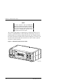
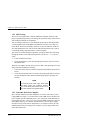
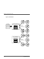
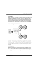
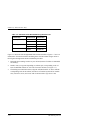
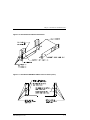
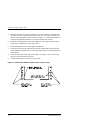
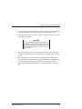
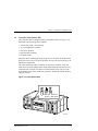
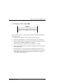
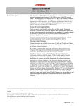
RAID Array 3000 Controller Shelf
From the storage shelf’s perspective, the controller receives the I/O requests from
the host and directs them to the devices. Since the controller processes all the I/O
requests, it eliminates the host-based processing that is typically associated with
reading and writing data to multiple storage devices.
The controller does much more than simply manage I/O requests: it provides the
ability to combine several ordinary disk drives into a single, high-performance
storage unit called a storageset. Storagesets are implementations of RAID technology, also known as a “Redundant Array of Independent Disks”. Every storageset shares one important feature: whether it uses two disk drives or 12, each
storageset looks like a single storage unit to the host.
You create storage units by combining disk drives into storagesets such as stripesets, RAIDsets, and mirrorsets, or by presenting them to the host as single-disk
units (see Figure 2–3).
Figure 2–3 Logical Units Created from Storagesets, Partitions, and Disk
Drives
Logical
Unit
Mirrorset
Logical
Unit
Partitioned
Storageset
Stripset
Raidset
Disk Drives
Logical
Unit
Striped
Mirrorset
Partitioned
Disk Drive
Logical
Unit
2–4
EK–SMCPQ–UG. C01
Chapter 2. RAID Array Controller
2.3
•
Stripesets (RAID 0) combine disk drives in serial to increase transfer or requests rates
•
Mirrorsets (RAID 1) combine disk drives in parallel to provide a highly reliable storage unit
•
RAID 4 provides striping with a fixed parity drive
•
RAIDsets (RAID 5) combine disk drives in serial - just like stripesets - but
also store parity data to ensure high reliability
•
Stripe mirrorsets (RAID 0 + 1) combine mirrorsets in serial to provide the
highest throughput and availability of any storage unit
Controller Reset and LED Indicators
Figure 2–4 illustrates the front panel of the controller. All LEDs are numbered
from left to right. The reset button (LED 0) flashes green about once every second (heartbeat) to indicate that the controller is operating normally. LEDs 1
through 4-display host and disk channel activity (amber). LED 5 (normally off)
comes on red during a controller failure. The LED/Reset switch interface is defined in Table 2–1.
Table 2–1 LED/Reset Switch Interface
LED #
Name
0
Heart Beat/LED Controller Reset Switch (green)
1
Host Channel 0 Activity LED (amber)
2
Host Channel 1 Activity LED (amber)
3
Disk Channel 0 Activity LED (amber)
4
Disk Channel 1 Activity LED (amber)
5
Fault LED (red)
EK–SMCPQ–UG. C01
2–5
RAID Array 3000 Controller Shelf
Figure 2–4 Controller Front Panel
Reset
H0
H1
D0
D1 F ault
Reset H0 H1 D0 D1 Fault
SHR-1049
2.4
Flexible RAID Set Configuration
In addition to its flexible hardware design, the controller’s firmware offers the
user the flexibility to configure RAID sets in several different ways:
2–6
•
RAID sets can comprise drives from any drive channel and SCSI ID.
•
A RAID set can contain all the drives connected to the controller, a single
drive, or any number of drives in between.
•
The controller supports RAID Levels 0, 1, 0+1, 4, and 5. It also supports
JBOD (Just a Bunch of Drives), allowing you to connect standalone disk
drives (such as a system disk) to the controller without making them members of a RAID set.
•
Each RAID set can be partitioned into smaller redundancy groups.
•
Any drive may be designated as a spare. Spares are global, meaning that in
the event of a drive failure, the controller will search for the first available
spare on any channel or SCSI ID and automatically begin rebuilding the
failed drive’s data.
•
All configuration and monitoring of RAIDsets accomplished via SWCC with
software platform kit.
EK–SMCPQ–UG. C01
Chapter 2. RAID Array Controller
2.5
Performance Enhancements
The controller employs a number of techniques to achieve as much performance
as possible from its design.
2.5.1 Custom Components
To increase performance and reliability, the controller’s core functions have been
encapsulated in four custom ASIC (Application Specific Integrated Circuits)
components as follows:
XOR ASIC: Used in the Exclusive -Or parity calculations employed by RAID
levels 4 and 5.
DMA ASIC: Controls the data path hardware for the various I/O ports
CPU Interface ASIC: Supports the controller’s MIPS R3000 RISC central
processing unit.
Memory Controller ASIC: Controls the memory system and supports data
movement on the internal bus at a maximum burst rate of 80 MB/second and a
maximum sustainable rate of 60 MB/second.
2.5.2 Efficient Write and Read Algorithms
Standard RAID write operations that involve parity, such as those in RAID levels
4 and 5, require multiple, time-consuming steps:
1.
Read data from the parity drive.
2.
Read existing data from the target data drives.
3.
Exclusive-Or the old parity, old data, and new data to generate new parity
data.
4.
Write the new parity data to the parity drive.
5.
Write the new data to the target data drives.
The controller uses several techniques to streamline write operations and significantly improve performance. All the techniques use the controller’s on-board
cache 60-nanosecond SIMMs.
NOTE
The controller will not operate without at least one
16 MB SIMM installed in its cache. Nor will it operate without an un-interruptable power supply
connected to the controller. Without a UPS, data
stored in the cache, but not yet written to the disk
drives, would be lost in the event of a power interruption.
EK–SMCPQ–UG. C01
2–7
RAID Array 3000 Controller Shelf
2.5.2.1 Write-Back Caching
When the host sends data to be written to a redundancy group the controller
stores the data in its cache and immediately reports to the host it has completed
the write. The controller eventually writes the data to the disk drives when the
write can be done most efficiently, or when the controller must flush the cache to
make room for other data or to prepare for a shutdown.
Write-back caching makes the host more responsive to the user, since the host
does not have to wait for a lengthy RAID write before proceeding to another
task.
2.5.2.2 Write Gathering
The controller will attempt to consolidate multiple writes destined for contiguous
blocks and then write the entire data block in one operation. The controller stores
the data in cache until it performs the write. Ideally, the controller will wait until
it has gathered enough data to fill an entire stripe. This enables the controller to
avoid reading from the parity and data drives before making the write. All it has
to do is calculate parity from the data it already has in its cache, then write the
data and parity to the drives. Even if the controller cannot accumulate enough
data to fill a stripe, the consolidation of small writes can reduce the number of
read/write operations that must take place.
2.5.2.3 Write On Top
If the host commands that data be written to disk, and data for that address is
pending in the controller’s cache, the controller writes the new data on top of the
old in the cache. Only the new data is eventually written to the disk drives.
2.6
RAID Levels Supported
The RAID Array 3000 controller supports the following RAID levels:
Table 2–2 RAID Levels Supported
RAID Level
Striping without parity
1
Mirroring
0+1
Striping and mirroring
4
Striping with fixed parity drive
5
Striping with floating parity drive
JBOD
2–8
Description
0
“Just a Bunch of Drives”
EK–SMCPQ–UG. C01
Chapter 2. RAID Array Controller
There are some restrictions you must adhere to when creating a RAID set using
the RAID 3000 shelf. The minimum and maximum number of drives required to
support each RAID level is listed in Table 2–3.
Table 2–3 Shelf RAID Set Restrictions
*
RAID Level
Min. No. of
Drives
Max. No. of
Drives
JBOD
1
1
0
2
24
1
2
24
0+1*
4
16
4
3
24
5
3
24
Must be even number.
2.6.1 RAID 0
RAID 0 breaks up data into smaller chunks and writes each chunk to a different
drive in the array. The size of each chunk is determined by the controller’s chunk
size parameter, which you set in the course of creating a RAID set.
The advantage of RAID 0 is its high bandwidth. By breaking up a large block of
data into smaller chunks, the controller can use multiple drive channels to write
the chunks to the disk drives. Furthermore, RAID 0 involves no parity calculations to complicate the write operation. Likewise, a RAID 0 read operation employs multiple drives to assemble a single, large data block. This makes RAID 0
ideal for applications such as graphics, video, and imaging that involve the writing and reading of large, sequential blocks. Figure 2–5 shows a diagram of a
RAID 0 write.
CAUTION
The lack of parity means that a RAID 0-disk array
offers no redundancy and thus cannot recover
from a drive failure.
EK–SMCPQ–UG. C01
2–9
RAID Array 3000 Controller Shelf
Figure 2–5 RAID 0 Write
Host Data
1011
0110
1010
0101
0000
0001
1100
1111
0111
1010
Controller divides the
data into chunksized units
1011
0110
1010
0101
0000
Striped data
written to the array
There is still data left
so the Controller
repeats the process
0001
1100
1111
0111
1010
Striped data
written to the array
SHR-1054
2–10
EK–SMCPQ–UG. C01
Chapter 2. RAID Array Controller
2.6.2 RAID 1
RAID 1 (also known as mirroring or shadowing) takes data sent by the host and
duplicates it on all the drives in an array. The result is a high degree of data
availability, since you can lose all but one drive in the array and still have full
access to your data. This comes at a price: a RAID 1 array requires multiple
drives to achieve the storage capacity of a single drive. Figure 2–6 illustrates a
RAID 1 write.
Figure 2–6 Diagram of a RAID 1 Write
Host Data
0010
1011
0110
Controller writes
data from cache
to all drives in
the array
SHR-1055
A RAID 1 array will show up on the monitor as “degraded” when at least one
drive fails, even if two or more members of the redundancy group remain in
good working order. As long as at least two working drives remain in the array,
you may continue to run the array in degraded mode without putting data in
jeopardy.
2.6.3 RAID 0+1
RAID 0+1 (see Figure 2–7) combines RAID 0 (striping) with RAID 1 (mirroring). In RAID 0+1 write, the controller breaks up the data block from the host
into smaller chunks, then writes the chunks to half the drives in the array, while
writing duplicate chunks to the remaining drives.
EK–SMCPQ–UG. C01
2–11
RAID Array 3000 Controller Shelf
Figure 2–7 Diagram of RAID 0+1 Write
Host Data
1110
1101
1011
Controller divides
the data into
chunksized units
1110
1101
1011
Striped data written
to half the drives
Striped data mirrored
to the remaining drives
SHR-1056
In the event of a drive failure, a RAID 0+1 array will enter degraded mode and
continue to operate by substituting the failed drive with its mirror.
When the controller creates a RAID 0+1 set, it first sorts the drives by channel
number and SCSI ID. Then it stripes the data across every other drive and forms
a mirrored pair with the first two drives, another mirrored pair with the second
two drives, and so on. Table 2–4 describes how the controller uses the drives in a
RAID 0+1 set.
Table 2–4 RAID 0+1 Example
2–12
Drives Selected
Function
Channel 1, ID 0
First member of stripe set.
Channel 1, ID 1
Mirror of channel 1, ID 0
Channel 1, ID 2
Second member of stripe set
Channel 2, ID 0
Mirror of channel 1, ID 2
Channel 2, ID 1
Third member of stripe set
Channel 2, ID 2
Mirror of channel 2, ID 1
EK–SMCPQ–UG. C01
Chapter 2. RAID Array Controller
2.6.4 RAID 4
RAID 4 (Figure 2–8) breaks up host data into chunks, calculates parity by performing an exclusive-or on the chunks, and then writes the chunks to all but one
drive in the array and the parity data to the last drive. When the host requests
data from the disk drives, the controller retrieves the chunks containing the addressed data, reconstitutes the data from the chunks, and passes the data to the
host.
Figure 2–8 Diagram of a RAID 4 Write
Host Data
0011
1011
0110
1110
0110
0000
1111
1110
Controller divides the
data into chunksized units
and calculates parity
0011
1011
0110
XOr 1110
0110
0000
1111
1110
Striped data and parity
written to the array
Parity = 0000
There is still data left
so the Controller
repeats the Process
0011
1011
0110
XOr 1110
Parity =
0110
0000
1111
1110
Striped data and parity
written to the array
0111
SHR-1057
EK–SMCPQ–UG. C01
2–13
RAID Array 3000 Controller Shelf
In the event of a single drive failure, a RAID 4 array will continue to operate in
degraded mode. If the failed drive is a data drive, writes will continue as normal,
except no data will be written to the failed drive. Reads will reconstruct the data
on the failed drive by performing an exclusive-or operation on the remaining
data in the stripe and the parity for that stripe. If the failed drive is a parity drive,
writes will occur as normal except no parity will be written. Reads will simply
retrieve data from the data disks. There will be no deterioration in controller performance while a RAID set is in degraded mode.
In general, RAID 4 is best suited for applications such as graphics, imaging, or
video that call for reading and writing large, sequential blocks of data. However,
you may find that RAID 4 is preferable to RAID 5 even for applications characterized by many small I/O operations, such as transaction processing. This is due
to the controller’s intelligent caching, which efficiently handles small I/O reads
and writes, and to the relatively less complex algorithms needed to implement
RAID 4.
The benefits of RAID 4 disappear when you have many, small I/O operations
scattered randomly and widely across the disks in the array. RAID 4’s fixed parity disk becomes a bottleneck in such applications, as the following example illustrates. Let’s say the host instructs the controller to make two small writes. The
writes are widely scattered, involving two different stripes and different disk
drives. Ideally, you would like both writes to take place at the same time, but
RAID 4 makes this impossible, since the writes must take turns accessing the
fixed parity drive. For this reason, RAID 5 is the better choice for widely scattered, small write operations.
CAUTION
RAID 4 can withstand a single failure and handle
I/O activity without interruption in degraded mode
until the failed drive is rebuilt. If a second drive
fails while the RAID set is in degraded mode, the
entire RAID set will fail.
2.6.5 RAID 5
RAID 5 (Figure 2–9) addresses the bottleneck issue for barrages of widely scattered, small I/O operations. Like RAID 4, RAID 5 breaks up data into chunks,
calculates parity, and then writes the chunks in stripes to the disk drives, saving
one drive one each stripe for the parity data. Unlike RAID 4, however, RAID 5
changes the parity drive on each stripe. This means, for instance, that a write operation involving drive 2 on stripe 1 can conceivably take place at the same time
as a write involving drive 3 on stripe 2, since they would be addressing different
parity drives.
2–14
EK–SMCPQ–UG. C01
Chapter 2. RAID Array Controller
Figure 2–9 Diagram of a RAID 5 Write
Host Data
1101
0110
1011
0010
0111
1110
0001
0110
Controller divides the
data into chunksized units
and calculates parity
1101
0110
1011
XOr 0010
0111
1110
0001
0110
Striped data and parity
written to the array
Parity = 0010
There is still data left
so the Controller
repeats the Process
1011
0110
1011
XOr 0010
Parity =
0111
1110
0001
0110
Striped data and parity
written to the array
1110
SHR-1058
RAID 5 handles drive failures in the same manner as RAID 4, except the parity
is different for each stripe. The controller either uses the parity information on a
stripe to reconstruct its data or simply reads the data as normal, depending on the
location of the stripe’s parity drive.
EK–SMCPQ–UG. C01
2–15
RAID Array 3000 Controller Shelf
While RAID 5 is ideally suited for applications with many, small I/O operations,
there is no reason why it cannot function equally well for applications with large,
sequential I/O operations. This makes RAID 5 an excellent all-purpose RAID
level.
CAUTION
RAID 5 can withstand a single failure and handle
I/O activity without interruption in degraded mode
until the failed drive is rebuilt. If a second drive
fails while the RAID set is in degraded mode, the
entire RAID set will fail.
2.6.6 JBOD
JBOD, which stands for “Just a Bunch of Disks”, makes it possible to connect
one or standalone disk drives to the controller. A JBOD disk drive is not part of a
redundancy group, even though the controller assigns a redundancy group number to the drive. This number becomes that logical unit number (LUN) that the
host will use to address the drive.
One use for JBOD is to connect a system disk drive to the controller. The drive
does not become part of a RAID set, but it is made available to the host on the
same SCSI bus as the other devices controlled by the controller.
2.7
System Parameters
The system parameters allow the user to customize certain aspects of the controller via the SWCC Graphical User Interface.
2.8
Redundant Operation
When operating in a redundant configuration, the two controllers are linked such
that, in case of a failure, the surviving controller can access the other controller’s
cache memory and complete all operations that were in progress when the failure
occurred. The controllers support two different configurations:
2–16
•
ACTIVE / ACTIVE: One host port is active on each controller. The other
port on each controller is passive and only used if the peer controller fails.
This configuration is recommended.
•
ACTIVE / PASSIVE: Both host ports on one controller are active. The
other controller’s ports are both passive and only used if the primary controller fails.
EK–SMCPQ–UG. C01
Chapter 2. RAID Array Controller
When one controller fails, the survivor will process all I/O requests until the
failed controller is repaired and powered on. The subsystem will then return to its
previous state (i.e., ACTIVE / ACTIVE or ACTIVE / PASSIVE).
2.8.1 Initialization
During initialization, the firmware in the RAID 3000 verifies that both controllers have consistent configurations including identical memory cache and system
parameters. If the controller setups are incompatible, the set is not bound and
each controller operates in stand-alone mode.
2.8.2 Message Passing
Information is shared between the two controllers by a collection of messages
passed through the backplane connectors. The messages provide configuration
data as well as a heartbeat which is transmitted by each controller every 500 ms.
If a controller does not receive a heartbeat within one second, it assumes the peer
controller has become inoperable and begins failing over.
If the controllers cannot exchange messages due to communication problems
over the backplane, they will break the connection and each controller will
switch to a stand-alone mode.
2.8.3 Failover
Failover describes the process of transferring data from a failed controller to a
survivor and completing any active tasks. When one controller begins the failover process, it sends a reset to the other controller, which prevents the failing
unit from processing any more information and enables any host ports that are
passive. It then downloads the failed controller’s cache to its unused portion of
cache and begins acting upon that data.
While downloading the data, the controller responds to I/O by disconnecting (if
allowed) and waiting approximately three seconds before reconnecting and presenting a BUSY status. The delay is to prevent host operating systems from
seeing too many errors and fencing off the controller.
EK–SMCPQ–UG. C01
2–17
RAID Array 3000 Controller Shelf
2.9
Environmental
The controller incorporates a set of on board sensors to detect abnormal operating conditions that may affect data safety.
2.9.1 Backup Power Management
The controller must be connected to the Uninterruptable power supply (UPS) to
prevent the subsystem cache from being corrupted during unexpected losses of
power. If no backup power supply is provided, the controller will remain off-line
and reject all I/O requests with a status of Check Condition/Hardware Error.
During normal operation, RAID 3000 ac power is supplied from a line source
through both power cords to both power supplies. Conditions of poor or no power
causes the following UPS responses:
Table 2–5 Response to Various AC Power Conditions
Condition
Response
Low line voltage
UPS compensation circuit automatically increases output voltage, without placing load on the UPS battery.
No line voltage
(AC loss)
UPS switches to the battery which supplies power to the
RAID 3000 maintaining full functionality.
UPS signals RAID 3000 controller of impending power
down. Caching is disabled but the RAID 3000 continues
to service host requests and begins to flush cache to
disk.
2–18
UPS low-battery warning
UPS signals RAID 3000 controller of impending power
down. Subsystem discontinues host services. Cache
flush is completed.
UPS power down
UPS shuts itself off, preventing complete battery discharge. All data has been written to disk.
EK–SMCPQ–UG. C01
3
Installation and Maintenance
This chapter describes how to install the Controller Shelf in a RETMA or metric-style
storage cabinet and then make the cable connections to the UPS, Device Expansion
Shelves and host system. The maintenance section describes how to interpret the status
of the LEDs on the front panel of the Controller Shelf. The chapter also describes how to
replace a Field Replaceable Unit (FRU).
3.1
Installation Guidelines
The Controller Shelf installation process consists of mounting the support brackets for the specific number of shelves in your subsystem configuration, setting
the UltraSCSI bus termination and target ID addresses, and making the power
and SCSI cable connections between the rackmount components. The section is
divided into four separate cabling procedures, one for each of the number of Device Expansion Shelves in your specific subsystem configuration.
CAUTION
To prevent the possible loss of data, always shutdown your subsystem from the StorageWorks
Command Console (SWCC). Do not turn off system power before shutdown is issued. When
shutdown is issued from SWCC, the controller first
flushes the cache to the disk drive, then stops
blinking.
Use the following guidelines when installing the Controller and Device Expansion Shelves. They apply to both RETMA and metric cabinet designs.
•
For stability and safety, arrange the components in the cabinet using a bottom-up approach.
•
Cable length is critical when locating the shelves in the cabinet. Keep
shelves grouped together to minimize cable length problems.
EK–SMCPQ–UG. C01
3–1
RAID Array 3000 Controller Shelf
3.2
•
Install the UPS below the shelves and as low as possible in the cabinet.
•
Ensure there is a approximate two-inch gap between the bottom of the controller shelf and the UPS to allow cable routing between the front panel connectors and connectors at the back of the units.
Installing Shelves in the Cabinet
Determining the best location to install the Controller and Device Expansion
Shelves in the cabinet depends on the number of expansion shelves in your subsystem configuration. The shelves should be grouped as shown Figures 3–1
through 3–4. Figure 3–1 shows a single Device Expansion Shelf installation.
Figures 3–2, 3–3, and 3–4 show a two, three, and four shelf installation, respectively.
Install the UPS at the bottom of the cabinet with the subsystem shelves directly
above. The host system (not shown) can reside between the UPS and the subsystem shelf group.
Note that the Controller Shelf in each figure is located directly below the first
Device Expansion Shelf. This minimizes the distance between the connectors to
enable the 0.5 meter SCSI cable connections between the modules in the Controller Shelf and each Device Expansion Shelf.
NOTES
• The distance between shelves should not exceed one 1.5 inches.
• Because of power cord lengths, the distance
between the last Device Expansion Shelf at the
top of a shelf group and the UPS should not exceed 45 inches.
The target SCSI bus addresses of the drives in the Device Expansion Shelves
(shown on each storage device in Figures 3–1 through 3–4) are controlled by a
switch on the side of the personality I/O module in each expansion shelf. In a
single expansion shelf configuration, the IDs are 0–5. In a double expansion shelf
configuration, the IDs in both expansion shelves are also 0–5 because each shelf
is connected to a separate device I/O bus from the controller.
In a three and four-shelf configuration (Figures 3–3 and 3–4, respectively), the
second expansion shelf on each device I/O bus is connected to the first via a
Trilink adapter and must be set to 8–13.
3–2
EK–SMCPQ–UG. C01
Chapter 3. Installation and Maintenance
Figure 3–1 Recommended Single Expansion Shelf Installation
P
/
S
P
/
S
P
/
S
P
/
S
5
4
3
2
1
Device
Expansion
Shelf
0
Controller
Shelf
UPS
SHR-1096
EK–SMCPQ–UG. C01
3–3
RAID Array 3000 Controller Shelf
Figure 3–2 Recommended Controller Shelf Installation (Two Expansion
Shelves)
P
/
S
P
/
S
P
/
S
P
/
S
P
/
S
P
/
S
5
4
3
2
1
0
5
4
3
2
1
0
SHR-1097
3–4
EK–SMCPQ–UG. C01
Chapter 3. Installation and Maintenance
Figure 3–3 Recommended Controller Shelf Installation (Three Expansion Shelves)
P
/
S
P
/
S
P
/
S
13
12
11
10
9
8
P
/
S
5
4
3
2
1
0
P
/
S
P
/
S
5
4
3
2
1
0
P
/
S
P
/
S
SHR-1098
EK–SMCPQ–UG. C01
3–5
RAID Array 3000 Controller Shelf
Figure 3–4 Recommended Installation (Four Expansion Shelves)
P
/
S
P
/
S
13
12
11
10
9
8
P
/
S
P
/
S
13
12
11
10
9
8
P
/
S
P
/
S
5
4
3
2
1
0
P
/
S
P
/
S
5
4
3
2
1
0
P
/
S
P
/
S
SHR-1099
3–6
EK–SMCPQ–UG. C01
Chapter 3. Installation and Maintenance
3.2.1
Installing Shelf Supports
After you determine the desired shelf slot locations in your cabinet, install the
shelf support mounting kits supplied with the shelves. Shelf support mounting
kits for the RETMA and metric style cabinets are included with each shelf assembly. The UPS is rack mounted using custom adjustable rail brackets. Table
3–1 lists the shelf support mounting kits and identifies the documents and procedures that contain the instructions needed to install them.
Table 3–1 Shelf Support Mounting Kits and Installation Guides
Cabinet Style
Shelf Support
Kit Part No.
Installation Guide/Part No.
RETMA Cabinet Installation
(round hole).
70-33381-01
See Section 3.2.1.1.
RETMA Cabinet Installation
(square hole).
70-33381-01
See Section 3.2.1.2.
Metric Cabinet Installation
BA35X-RD
SW500 and SW800 Cabinet
Metric Shelf Bracket Kit Installation Guide (EK–35XRD–ID)
UPS Installation into a
RETMA or Metric Cabinet
74-53154-01/02
(plus hardware)
See Section 3.2.2 below.
3.2.1.1
Installing Shelf Supports in a RETMA Cabinet (Round Hole)
Use the following procedure to install the shelf support kit into a RETMA cabinet with round holes in the mounting rails (see Figure 3–5).
1.
Open the kit and ensure it contains the items listed in Table 3–2.
Table 3–2 RETMA Cabinet Shelf Support Parts List
Item
Part Number
Description
Qty.
1
74-46419-01
Shelf Retainer Bracket, (0.25 inch)
4
2
74-46419-02
Shelf Retainer Bracket, (1.50 inch)
2
3
74-48220-01
Shelf Support – BA350-SA
1
4
74-48220-02
Shelf Support – BA350-SA
1
5
74-48223-01
Nut Plate
2
6
74-50250-01
Support Bracket – BA350-24/U
1
7
90-00063-37
Screw – 10 x 32
14
8
90-06565-00
Nut – 10 x 32
2
EK–SMCPQ–UG. C01
3–7
RAID Array 3000 Controller Shelf
2.
Determine the mounting location in your cabinet.
3.
Install the left shelf support by aligning the bracket and cabinet rail holes
and then securing the support to the cabinet using two screws (item 7, Figure
3–5). Do not tighten screws.
4.
Install the nut plate (item 5, Figure 3–5) behind the left rail and secure with
three screws. Tighten all five screws.
5.
Repeat steps 2, 3, and 4 to install the right shelf support in the cabinet.
6.
Install the support bracket (item 6, Figure 3–5) by securing the bracket studs
with two plate nuts (item 8, Figure 3–5).
7.
Install a shelf retainer bracket (item 1, Figure 3–5) in the rear slot of the left
shelf support and secure with two screws.
8.
Repeat step 7 to secure a shelf retainer bracket to the right shelf support.
9.
Place the Controller Shelf on the cabinet shelf supports and slide the shelf
completely to the rear of the cabinet.
10. Install two shelf retainer brackets (item 1, Figure 3–5) to the left and right
rails of the cabinet and secure with two screws. The Controller Shelf is now
safely mounted in the cabinet.
3.2.1.2
Installing Shelf Supports in a RETMA Cabinet (Square Hole)
Use the following procedure to install the shelf supports into a RETMA cabinet
with square holes in the mounting rails (see Figure 3–5).
3–8
1.
Open the kit and ensure it contains the items listed in Table 3–2.
2.
Retrieve six washers (part no.: 90-06664-00) from general packaging.
3.
Determine the position of the shelf supports in the cabinet.
4.
Install the left shelf support by aligning the support and cabinet rail holes
and then securing the support to the cabinet using three screws (item 7, Figure
3–5) and washers. Tighten the screws.
5.
Repeat steps 3, and 4 to install the right shelf support in the cabinet. Align
the support with the left unit and tighten the screws.
6.
Install the support bracket (item 6, Figure 3–5) by securing the bracket studs
with two plate nuts (item 8, Figure 3–5).
7.
Install a shelf retainer bracket (item 1, Figure 3–5) in the rear slot of the left
shelf support and secure with two screws.
EK–SMCPQ–UG. C01
Chapter 3. Installation and Maintenance
8.
Repeat step 7 to secure a shelf retainer bracket to the right shelf support.
9.
Place the Controller Shelf on the cabinet shelf supports and slide the shelf
completely to the rear of the cabinet.
10. Install two shelf retainer brackets (item 1, Figure 3–5) to the left and right
rails of the cabinet and secure with two screws. The Controller Shelf is now
safely mounted in the cabinet.
Figure 3–5 RETMA Cabinet Shelf Supports
3.2.2
Installing UPS Brackets
The shelf brackets that support and secure the UPS in the cabinet are a custom
design. The following procedure describes how to install the rack-mount brackets. It applies to both cabinet designs – RETMA and metric. You will need the
following items to properly install the UPS brackets in your style cabinet:
•
2 UPS rack-mount brackets (74-53154-01 and -02)
•
1 Bag (Table 3–3 lists contents) of mounting hardware (99-06557-05)
•
Phillips-head screwdriver
EK–SMCPQ–UG. C01
3–9
RAID Array 3000 Controller Shelf
Table 3–3 UPS Rack-mount Bracket Mounting Hardware List
Cabinet Style
Hardware Item
Part Number
RETMA (round hole)
Screw
90-00063-39
U-Nut
90-07786-00
Screw
90-40331-01
Cage Nut
90-11476-01
Washer
90-0664-00
RETMA (square hole)
Figure 3–6 shows the left and right-hand UPS bracket assemblies. Figures 3–7 and 3–8
illustrate the front and rear bracket mounting holes for both cabinet designs. Refer to
these figures throughout the bracket installation procedure.
1.
Determine the mounting location in your cabinet (bottom of cabinet recommended
for stability).
2.
Install U-nuts (or cage nuts depending on cabinet style) corresponding to the “E”
holes for RETMA cabinets or “M” holes for metric cabinets (see Figure 3–7).
3.
If installing into a RETMA cabinet, align the left-hand bracket “E” holes with the
corresponding holes in the cabinet (extend rear of bracket beyond rail for installation), insert two screws, and secure with to cabinet with a cage nut or U-nut.
3–10
EK–SMCPQ–UG. C01
Chapter 3. Installation and Maintenance
Figure 3–6 UPS Rack-mount Bracket Assemblies
Figure 3–7 UPS Bracket RETMA and Metric Hole Locations (Front)
EK–SMCPQ–UG. C01
3–11
RAID Array 3000 Controller Shelf
4.
Pull and extend the rear bracket assembly until it reaches the hole mounting channel at the rear of the cabinet and install cage nuts (or U-nuts) at the rear of the rail
into the corresponding holes in the cabinet (see Figure 3–7). Extend the bracket beyond rail and tighten the hardware to secure the bracket to the cabinet.
5.
Install the UPS right-hand bracket on the right side of the cabinet using the same
hole patterns and hardware used in steps 2 and 3.
6.
Ensure both brackets are level and tighten all hardware.
7.
Carefully lift and insert the UPS onto the brackets and push the unit back into the
cabinet until the mounting holes in each flange aligns with the corresponding holes
in the cabinet.
8.
Secure the front panel of the UPS to the cabinet (see Figure 3–8 for correct holes)
using two SST flat-washers and screws.
9.
Connect the UPS power cord to the ac power strip.
Figure 3–8 UPS Bracket RETMA and Metric Hole Locations (Rear)
3–12
EK–SMCPQ–UG. C01
Chapter 3. Installation and Maintenance
3.3
Power and SCSI Cable Connection Procedures
This section contains the power and SCSI cabling procedures for a single or
multiple Device Expansion Shelf subsystem installation. Each procedure describes how to connect the Controller Shelf to the Device Expansion Shelve(s),
the host system, the UPS, and the maintenance PC. Your Controller and Device
Expansion shelf shipment contains all of the power, serial control, and SCSI data
cables required to connect and configure your system. These cables, along with
two Trilink adapter connectors allow you to create a single or multiple storage
subsystem as shown in Figures 3–1 through 3–4.
The section is divided into four procedures that describe how to connect a single
or multiple-shelf configuration. Each is supported by a wiring diagram and is independent of the other three. Proceed to the procedure that applies to the number
of Device Expansion Shelves you are connecting to the Controller Shelf.
NOTE
All four cabling procedures describe how to connect your subsystem to a single host via the host
I/O module 0 connector on the Controller Shelf. The
procedures are the same for host I/O module 1.
Also, no connections are shown to the Host Out
connector on the I/O module. This connector is
electrically the same as Host In and is used for
mid-bus connections in a multiple-host configuration.
EK–SMCPQ–UG. C01
3–13
RAID Array 3000 Controller Shelf
3.3.1
SCSI Bus Target Addresses and Termination
NOTE
The SCSI bus address switch on the Controller
Shelf device I/O module has been disabled. It does
affect or control the SCSI bus addresses of the devices in the Device Expansion Shelves. The target
addresses of the disk drives are set by address
switch S3 on the personality module in each Device
Expansion Shelf.
The SCSI bus device address and termination switches should be set before connecting the SCSI cables between the Controller and Device Expansion Shelves.
The SCSI bus addresses of the devices in each Device Expansion Shelf is set by
address switch (S3) on the side of the personality I/O module in each shelf.
The SCSI bus termination on each device bus is set by the SCSI bus termination
switch (S4) on the device I/O module of the Controller Shelf and the Personality
I/O module on each Device Expansion Shelf.
The correct SCSI bus ID addresses and termination switch settings for single and
multiple Device Expansion Shelf installations are shown on the diagrams that
support the four following cabling procedures.
3–14
EK–SMCPQ–UG. C01
Chapter 3. Installation and Maintenance
3.3.2
Cabling a Single Device Expansion Shelf Subsystem
(See Figures 3–9 and 3–10)
1.
Ensure the physical installation phase of installing and securing shelf brackets and shelves (including the UPS) has been accomplished and that the
shelves are secured within the shelf bracket the shelf lock provided.
2.
Remove the device I/O module from the Controller Shelf and ensure the
switch positions of SCSI bus termination switch S4 are set as shown in Figure 3–9. Replace the module in the Controller Shelf.
3.
Remove the personality I/O module from the Device Expansion Shelf and
set SCSI bus termination switch S4 on this module as shown in Figure 3–9.
4.
Ensure SCSI bus address switch S3 on the personality I/O module is set for
the device addresses as shown in Figure 3–9. Replace the module in the Device Expansion Shelf.
5.
Connect the black ac power cords (supplied with the shelves) from the ac
power source to the outside power supply on each shelf (see Figure 3–10).
6.
Connect the gray power cables from the inside power supply on each shelf to
the power receptacles on the back of the UPS (ensure the UPS is connected
to an ac source).
7.
Connect a 0.5-meter SCSI cable (BN37A-0E) from the top SCSI connector
on the Controller Shelf device I/O module (device bus 1) and the SCSI connector on the front of the personality I/O module on the Expansion Shelf.
8.
Connect a 5-meter SCSI cable (BN37A-05) between the host-in connector
on the Controller Shelf host 0 I/O module (bottom connector) and the corresponding connector on the host system.
9.
Connect the maintenance serial control cable (17-04730-01) from the CTR 0
connector on the Controller Shelf host 0 I/O module to the corresponding
connector on the maintenance PC.
10. Connect the UPS serial control cable (17-04729-01) from the UPS connector
Controller Shelf host 0 I/O module to the like connector on the UPS.
11. Install jumper connector 12-49700-01 to the Controller Shelf UPS connector
on the host 1 I/O module.
CAUTION
To prevent possible damage to the equipment, the
input voltage level of the UPS must be set to your
specific line voltage before proceeding. Refer to the
UPS manual and set the input level to your ac
power source(s).
EK–SMCPQ–UG. C01
3–15
RAID Array 3000 Controller Shelf
12. After the UPS has been set to the correct input voltage level, set the UPS
low-battery warning option to five minutes (refer to UPS manual for instructions).
13. This completes the Controller and Device Expansion Shelf cabling procedure. Dress and ty-wrap related cable groups, and then refer to the RAID Array 3000 Getting Started and Command Console Installation and User
Guides for information describing how to setup and configure your subsystem.
Figure 3–9 Controller/ Single Device Expansion Shelf Cabling Diagram
OFF ON
1
2
3
4
SCSI Bus
Termination
Switch (S4)
DEVICE EXPANSION SHELF # 1
P/S
A
Personality I/O
Module
ON
OFF
1 2 3 4 5 6 7
SCSI Bus Address
Switch (S3)
P/S
B
SCSI Cable
BN37A-0E
CONTROLLER SHELF
Host 0 I/O Device
Module I/O Module
CTR 0
P/S
A
P/S
B
SCSI Cable
BN37A-05
Serial Control
Cable
(17-04730-01)
To Host System
To
Maintenance
PC
OFF ON
1
2
3
4
SCSI Bus
Termination
Switch (S4)
SHR-1117
3–16
EK–SMCPQ–UG. C01
Chapter 3. Installation and Maintenance
Figure 3–10 AC Power Wiring Diagram
To
Device Expansion
Shelves 2, 3, and 4
DEVICE EXPANSION SHELF #1
P/S
A
P/S
B
CONTROLLER SHELF
P/S
A
Host 0 I/O
Module
P/S
B
UPS
UPS Control
(17-04729-01)
Gray Power Cords
AC Power
Receptacles
UPS
Black Power Cords
AC Power
Source
SHR-1116
EK–SMCPQ–UG. C01
3–17
RAID Array 3000 Controller Shelf
3.3.3 Cabling a Two Device Expansion Shelf Subsystem
(See Figures 3–10 and 3–11)
1.
Ensure the physical installation phase of installing and securing shelf brackets and shelves (including the UPS) has been accomplished and that the
shelves are secured within the shelf bracket the shelf lock provided.
2.
Remove the device I/O module from the Controller Shelf and ensure the
switch positions of SCSI bus termination switch S4 are set as shown in Figure 3–9. Replace the module in the Controller Shelf.
3.
Remove the personality I/O module from Device Expansion Shelf # 1 and
set SCSI bus termination switch S4 and SCSI bus address switch S3 on this
module as shown in Figure 3–11.
4.
Remove the personality I/O module from Device Expansion Shelf # 2 and
repeat step 3.
5.
Connect the black ac power cords (supplied with the shelves) from the ac
power source to the outside power supply on each shelf (see Figure 3–10).
6.
Connect the gray power cables from the inside power supply on each shelf to
the power receptacles on the back of the UPS (ensure the UPS is connected
to an ac source.
7.
Connect a 0.5-meter SCSI cable (BN37A-0E) from the top SCSI connector
on the Controller Shelf device I/O module (device bus 1) and the SCSI connector on the front of the personality I/O module on the Expansion Shelf.
8.
Connect a second 0.5-meter SCSI cable (BN37A-0E) from the bottom SCSI
connector on the Controller Shelf device I/O module (device bus 2) and the
SCSI connector on the front of the personality I/O module on the Device
Expansion Shelf # 2.
9.
Connect a 5-meter SCSI cable (BN37A-05) between the host-in connector
on the Controller Shelf host 0 I/O module (bottom connector) and the corresponding connector on the host system.
10. Connect the maintenance serial control cable (17-04730-01) from the CTR 0
connector on the Controller Shelf host 0 I/O module to the corresponding
connector on the maintenance PC.
11. Connect the UPS serial control cable (17-04729-01) from the UPS connector
Controller Shelf host 0 I/O module to the like connector on the UPS.
12. Install jumper connector 12-49700-01 to the Controller Shelf UPS connector
on the host 1 I/O module.
3–18
EK–SMCPQ–UG. C01
Chapter 3. Installation and Maintenance
Figure 3–11 Controller/ Two Device Expansion Shelf Cabling Diagram
DEVICE EXPANSION SHELF # 2
P/S
A
OFF ON
1
2
3
4
SCSI Bus
Termination
Switch (S4)
P/S
B
DEVICE EXPANSION SHELF # 1
P/S
A
Personality I/O
Module
Personality I/O
Module
ON
OFF
1 2 3 4 5 6 7
SCSI Bus Address
Switch (S3)
P/S
B
SCSI Cable
BN37A-0E
CONTROLLER SHELF
Device
Host 0 I/O
Module I/O Module
CTR 0
P/S
A
P/S
B
Serial Control
Cable
(17-04730-01)
SCSI Cable
BN37A-05
To
Maintenance
PC
To Host System
SHR-1118
EK–SMCPQ–UG. C01
3–19
RAID Array 3000 Controller Shelf
CAUTION
To prevent possible damage to the equipment, the
input voltage level of the UPS must be set to your
specific line voltage before proceeding. Refer to the
UPS manual and set the input level to your ac
power source(s).
13. After the UPS has been set to the correct voltage level, set the UPS lowbattery warning option to five minutes (refer to UPS manual for instructions).
14. This completes the Controller and Device Expansion Shelf cabling procedure. Dress and ty-wrap related cable groups, and then refer to the RAID Array 3000 Getting Started and Command Console Installation and User
Guides for information describing how to setup and configure your subsystem.
3–20
EK–SMCPQ–UG. C01
Chapter 3. Installation and Maintenance
3.3.4 Cabling a Three Device Expansion Shelf Subsystem
(See Figures 3–10 and 3–12)
1.
Ensure the physical installation phase of installing and securing shelf brackets and shelves (including the UPS) has been accomplished and that the
shelves are secured within the shelf bracket the shelf lock provided.
2.
Remove the device I/O module from the Controller Shelf and ensure the
switch positions of SCSI bus termination switch S4 are set as shown in Figure 3–9. Replace the module in the Controller Shelf.
3.
Remove the personality I/O module from Device Expansion Shelf # 1 and
set SCSI bus termination switch S4 and SCSI bus address switch S3 on this
module as shown in Figure 3–12.
4.
Remove the personality I/O modules from Device Expansion Shelves # 2
and # 3 repeat step 3.
5.
Connect the black ac power cords (supplied with the shelves) from the primary ac power source to the outside power supply on each shelf (see Figure
3–10).
6.
Connect the gray power cables from the inside power supply on each shelf to
the power receptacles on the back of the UPS (ensure the UPS is connected
to a secondary ac source.
7.
Connect the single-connector end of a Trilink adapter to the SCSI connector
on the personality module in Device Expansion Shelf # 1. Tighten the
screws on the adapter to ensure it is firmly seated.
8.
Connect a 0.5-meter SCSI cable (BN37A-0E) from one connector on the
adapter to the top SCSI connector (device bus 1) on the front of the Controller Shelf device I/O module.
9.
Connect a second 0.5-meter SCSI cable (BN37A-0E) from the other connector on the adapter to the SCSI connector on the front of the personality
I/O module on the Device Expansion Shelf # 3.
10. Connect a third 0.5-meter SCSI cable (BN37A-0E) from the bottom SCSI
connector on the Controller Shelf device I/O module (device bus 0) to the
SCSI connector on the front of the personality I/O module on the Device
Expansion Shelf # 2.
11. Connect a 5-meter SCSI cable (BN37A-05) between the host-in connector
on the Controller Shelf host 0 I/O module (bottom connector) and the corresponding connector on the host system.
12. Connect the maintenance serial control cable (17-04730-01) from the CTR 0
connector on the Controller Shelf host 0 I/O module to the corresponding
connector on the maintenance PC.
EK–SMCPQ–UG. C01
3–21
RAID Array 3000 Controller Shelf
Figure 3–12 Controller/ Three Device Expansion Shelf Cabling Diagram
DEVICE EXPANSION SHELF # 3
P/S
A
1 2 3 4 5 6 7
SCSI Bus Address
Switch (S3)
Personality I/O
Module
OFF ON
1
2
3
4
SCSI Bus
Termination
Switch (S4)
ON
OFF
1 2 3 4 5 6 7
SCSI Bus Address
Switch (S3)
P/S
B
DEVICE EXPANSION SHELF # 1
P/S
A
ON
OFF
P/S
B
DEVICE EXPANSION SHELF # 2
P/S
A
Personality I/O
Module
OFF ON
1
2
3
4
SCSI Bus
Termination
Switch (S4)
Personality I/O
Module
P/S
B
OFF ON
1
2
3
4
SCSI Bus
Termination
Switch (S4)
ON
OFF
1 2 3 4 5 6 7
SCSI Bus Address
Switch (S3)
TRI
Link
SCSI Cable
BN37A-0E
CONTROLLER SHELF
Host 0 I/O
Device
Module I/O Module
CTR 0
P/S
A
P/S
B
Serial Control
Cable
(17-04730-01)
SCSI Cable
BN37A-05
To
Maintenance
PC
To Host System
SHR-1119
3–22
EK–SMCPQ–UG. C01
Chapter 3. Installation and Maintenance
13. Connect the UPS serial control cable (17-04729-01) from the UPS connector
Controller Shelf host 0 I/O module to the like connector on the UPS.
14. Install jumper connector 12-49700-01 to the Controller Shelf UPS connector
on the host 1 I/O module.
CAUTION
To prevent possible damage to the equipment, the
input voltage level of the UPS must be set to your
specific line voltage before proceeding. Refer to the
UPS manual and set the input level to your ac
power source(s).
15. After the UPS has been set to the correct input voltage level, set the UPS
low-battery warning option to five minutes (refer to UPS manual for instructions).
16. This completes the Controller and Device Expansion Shelf cabling procedure. Dress and ty-wrap related cable groups, and then refer to the RAID Array 3000 Getting Started and Command Console Installation and User
Guides for information describing how to setup and configure your subsystem.
EK–SMCPQ–UG. C01
3–23
RAID Array 3000 Controller Shelf
3.3.5 Cabling a Four Device Expansion Shelf Subsystem
(See Figures 3–10 and 3–13)
1.
Ensure the physical installation phase of installing and securing shelf brackets and shelves (including the UPS) has been accomplished and that the
shelves are secured within the shelf bracket the shelf lock provided.
2.
Remove the device I/O module from the Controller Shelf and ensure the
switch positions of SCSI bus termination switch S4 are set as shown in Figure 3–9. Replace the module in the Controller Shelf.
3.
Remove the personality I/O module from Device Expansion Shelf # 1 and
set SCSI bus termination switch S4 and SCSI bus address switch S3 on this
module as shown in Figure 3–13.
4.
Remove the personality I/O modules from Device Expansion Shelves # 2, #
3, and # 4 and repeat step 3.
5.
Connect the black ac power cords (supplied with the shelves) from the primary ac power source to the outside power supply on each shelf (see Figure
3–10).
6.
Connect the gray power cables from the inside power supply on each shelf to
the power receptacles on the back of the UPS (ensure the UPS is connected
to a secondary ac source.
7.
Connect the single-connector end of a Trilink adapter to the SCSI connector
on the personality module in Device Expansion Shelf # 1. Tighten the
screws on the adapter to ensure it is firmly seated.
8.
Connect the single-connector end of a second Trilink adapter to the SCSI
connector on the personality module in Device Expansion Shelf # 2. Tighten
the screws on the adapter to ensure it is firmly seated.
9.
Connect a 0.5-meter SCSI cable (BN37A-0E) from one connector on the
adapter connected to shelf # 1 to the top SCSI connector (device bus 1) on
the front of the Controller Shelf device I/O module.
10. Connect a second 0.5-meter SCSI cable (BN37A-0E) from the other connector on the adapter connected to shelf # 1 to the SCSI connector on the
front of the personality I/O module on the Device Expansion Shelf # 3.
11. Connect a third 0.5-meter SCSI cable (BN37A-0E) from the one connector
on the adapter connected to shelf # 2 to the bottom SCSI connector (device
bus 0) on the front of the Controller Shelf device I/O module.
12. Connect a fourth 0.5-meter SCSI cable (BN37A-0E) from the other connector on the adapter connected to shelf # 2 to the SCSI connector on the front
of the personality I/O module on the Device Expansion Shelf # 4.
3–24
EK–SMCPQ–UG. C01
Chapter 3. Installation and Maintenance
Figure 3–13 Controller/ Four Device Expansion Shelf Cabling Diagram
DEVICE EXPANSION SHELF # 4
P/S
A
P/S
B
DEVICE EXPANSION SHELF # 3
P/S
A
Personality I/O
Module
Personality I/O
Module
OFF ON
1
2
3
4
SCSI Bus
Termination
Switch (S4)
ON
OFF
1 2 3 4 5 6 7
SCSI Bus Address
Switch (S3)
P/S
B
SCSI Cable
BN37A-0E
DEVICE EXPANSION SHELF # 2
P/S
A
P/S
B
DEVICE EXPANSION SHELF # 1
P/S
A
Personality I/O
Module
TRI
Link
Personality I/O
Module
P/S
B
OFF ON
1
2
3
4
SCSI Bus
Termination
Switch (S4)
ON
OFF
1 2 3 4 5 6 7
SCSI Bus Address
Switch (S3)
TRI
Link
SCSI Cable
BN37A-0E
CONTROLLER SHELF
Device
Host 0 I/O
Module I/O Module
CTR 0
P/S
A
P/S
B
Serial Control
Cable
(17-04730-01)
SCSI Cable
BN37A-05
To
Maintenance
PC
To Host System
SHR-1120
EK–SMCPQ–UG. C01
3–25
RAID Array 3000 Controller Shelf
13. Connect a 5-meter SCSI cable (BN37A-05) between the host-in connector
on the Controller Shelf host 0 I/O module (bottom connector) and the corresponding connector on the host system.
14. Connect the maintenance serial control cable (17-04730-01) from the CTR 0
connector on the Controller Shelf host 0 I/O module to the corresponding
connector on the maintenance PC.
15. Connect the UPS serial control cable (17-04729-01) from the UPS connector
Controller Shelf host 0 I/O module to the like connector on the UPS.
16. Install jumper connector 12-49700-01 to the Controller Shelf UPS connector
on the host 1 I/O module.
CAUTION
To prevent possible damage to the equipment, the
input voltage level of the UPS must be set to your
specific line voltage before proceeding. Refer to the
UPS manual and set the input level to your ac
power source(s).
17. After the UPS has been set to the correct input voltage level, set the lowbattery warning option to five minutes (refer to UPS manual for instructions).
18. This completes the Controller and Device Expansion Shelf cabling procedure. Dress and ty-wrap related cable groups, and then refer to the RAID Array 3000 Getting Started and Command Console Installation and User
Guides for information describing how to setup and configure your subsystem.
3–26
EK–SMCPQ–UG. C01
Chapter 3. Installation and Maintenance
3.4
Controller Shelf Status LEDs
The Controller Shelf is equipped with two front-panel LEDs (see Figure 3–14)
that monitor the following error conditions:
• A shelf blower that is not operating
• An over-temperature condition
• A dc power problem
• External fault conditions
• Controller faults
When the shelf is operating properly, the green power LED is on and the amber
shelf fault LED is off. If a dc power problem develops, the power LED goes out
indicating a malfunction.
The amber shelf status LED is normally off. If an error condition occurs, the
LED comes on and an audible alarm sounds notifying the operator that an error
condition exists. Once the user has been notified and is aware of an error, the
alarm disable toggle switch enables the operator to disable the audible alarm by
using the switch.
Figure 3–14 Shelf Status LEDs
Fault LED DC Power
(Amber) LED (Green)
SHR-1063
EK–SMCPQ–UG. C01
3–27
RAID Array 3000 Controller Shelf
3.5
Controller LEDs
The LEDs on the front panel of the controller monitor host and disk channel activity and a controller fault condition. The reset button/LED flashes green approximately once every second (heartbeat) to indicate that the controller is operating normally. Figure 2–3, Chapter 2, identifies the LEDs. Table 2–1 describes
their functions.
3.6
Replacing Components (FRU’s)
This section describes how to replace an FRU in the RAID Array 3000 controller
shelf. The information is divided into the following subsections:
• Replacing a Host I/O or Device I/O SBB in the controller shelf
• Replacing a shelf power supply SBB
• Replacing the RAID controller
• Replacing the UPS
• Replacing a blower
• Replacing a controller memory cache module
NOTE
The rack-mount UPS is also field replaceable. Refer to the user’s guide supplied with the unit for the
order number and instructions of how to replace it.
Figure 3–15 is an exploded view that shows the Field Replaceable Units in the
controller shelf. Table 3–4 lists the units and their corresponding part numbers.
3–28
EK–SMCPQ–UG. C01
Chapter 3. Installation and Maintenance
Figure 3–15 Controller Shelf Field Replaceable Units
5
1
2
3
4
SHR-1052
Table 3–4 Controller Shelf Field Replaceable Units
Item
Qty.
Part Number
Description
1
2
30-48191-04
Power Supply, 180 W, 50/60 Hz, +5 V, +12V,
2
1*
70-33523-01
RAID Controller
3
2
70-33525--01
Host I/O Module
4
1
70-33067-05
Device I/O Module
5
2
70-29761-07
Blower Assembly
* Second (redundant) controller is optional
EK–SMCPQ–UG. C01
3–29
RAID Array 3000 Controller Shelf
3.6.1 Replacing a Host or Device I/O SBB
CAUTION
When you remove an SBB, the airflow through the
shelf is reduced. Always install the replacement
unit immediately to prevent overheating.
1.
Ensure the SCSI bus connected to the SBB is quiescent (no I/O activity).
2.
Disconnect the cables (or jumper) from the front panel of the SBB.
3.
Release the SBB from the shelf slot by squeezing the mounting tabs on the
SBB together and pulling it forward until clear of the shelf (Figure 3–16).
4.
Insert an identical model SBB in the slot and push it in until an audible click
is heard indicating the SBB is fully seated (SBB front panel mounting tabs
expand and engage the shelf).
5.
Observe that the SBB status LEDs are operating.
6.
Reconnect the cables and jumper (if installed on the original module).
Figure 3–16 Replacing the Host I/O SBB
SHR-1038
3–30
EK–SMCPQ–UG. C01
Chapter 3. Installation and Maintenance
3.6.2 Replacing a Power Supply SBB
CAUTION
When you remove a power supply, the airflow
through the shelf is reduced. Always install the replacement unit immediately to prevent overheating.
You can replace a dc power supply without affecting shelf operation using the
following procedure:
1.
Remove the ac input power cable from the shelf power supply.
2.
Squeeze the mounting tabs to release the unit and pull it out of the shelf.
3.
Insert the replacement power supply into the shelf slot, align the guide slots,
and then push it in until the SBB tabs lock into place.
4.
Connect the input power cable to the power supply ac receptacle.
5.
Observe the LEDs on the replacement power supply and ensure that the unit
is operating properly.
6.
If the shelf power is removed during power supply replacement, the controller must place the storage devices on-line sequentially at four-second intervals. Make sure the LEDs on both the power supply and the storage devices indicate normal operation.
EK–SMCPQ–UG. C01
3–31
RAID Array 3000 Controller Shelf
3.6.3 Replacing the RAID Controller
CAUTION
When you remove the controller, the airflow
through the shelf is reduced. Always install the replacement unit immediately to prevent overheating.
1.
Ensure the SCSI bus connected to the SBB is quiescent (no I/O activity).
2.
Grip the two locking latches on the front panel of the controller and pull
them forward until the controller disengages from its mounting slot (Figure
3–17).
3.
Transfer the SIMM(s) to the new controller.
4.
Remove the controller by sliding it forward and free of the shelf.
5.
Insert the replacement controller into the open slot, align the module into the
card guides, and gently slide it into the shelf until the connector engages the
backplane connector in the shelf.
6.
Turn the two front panel latches inward to seat the controller in the shelf
slot.
7.
Restore the configuration using SWCC.
Figure 3–17 Removing the Controller from the Shelf
SHR-1062
3–32
EK–SMCPQ–UG. C01
Chapter 3. Installation and Maintenance
3.6.4 Replacing the UPS
Proceed as follows to replace the UPS:
1.
Ensure the UPS power switch is set to off.
2.
Disconnect the shelf power cords from the rear receptacles on the UPS.
3.
Disconnect the UPS power cord from the wall outlet.
4.
Disconnect the serial control cable from the controller shelf.
5.
Remove the screws that secure the front panel of the UPS to the cabinet.
6.
Install the replacement UPS and replace the screws removed in step 5 to secure the unit.
7.
Reconnect the power cords and the serial control cable.
8.
Set the UPS output voltage level to your specific ac power source.
9.
Set the UPS power switch to on, set the UPS low-battery warning option to
five minutes (refer to UPS manual), and then power-up the shelf.
3.6.5 Replacing a Blower
WARNING
Only qualified service personnel should access the
rear of the shelf to replace a blower.
The controller shelf has two blowers mounted on the rear. Connectors on the
backplane provide the +12 Vdc to operate the blowers. When a blower fails, the
shelf status (amber) LED on the power supply SBB is OFF and an error message
is passed to the controller or host via the shelf status signal. The Device I/O assembly status LEDs indicate which blower has failed and then automatically
switches the remaining blower to high speed. Refer to the SBB I/O Module
User’s Guide (Part No.: EK-SBBIO-UG) supplied with the device expansion
shelf for additional LED and blower status information.
Use one of the following procedures to replace a blower (see Figure 3–18).
CAUTIONS
The blowers are dual-speed devices and should be
replaced only with identical units.
Shelf air flow is lost when a blower is removed. Replace immediately or damage can result.
EK–SMCPQ–UG. C01
3–33
RAID Array 3000 Controller Shelf
If you can access the blowers from the rear of the cabinet, proceed as follows:
1.
Use a Phillips-head screwdriver to remove the safety screw in the upper right
corner or lower left corner of the blower (see Figure 3–18).
2.
Press the upper and lower blower mounting tabs together to release the
blower.
Pull the blower straight out to disconnect it from the shelf power connector.
3.
4.
Align the replacement blower connector and push the blower straight in,
making sure that both mounting tabs lock in place.
Figure 3–18 Replacing a Blower Assembly
3–34
5.
Insert the safety screw.
6.
Verify that the shelf and all SBBs are operating properly by observing the
LEDs.
EK–SMCPQ–UG. C01
Chapter 3. Installation and Maintenance
If you cannot access the blowers from the rear of the cabinet, proceed as follows:
1.
Disconnect the cables from the front of the controller shelf and remove the
shelf from the cabinet.
2.
Use a Phillips-head screwdriver to remove the safety screw in the upper right
corner or lower left corner of the blower.
3.
Press the upper and lower blower mounting tabs together to release the
blower.
4.
Pull the blower straight out to disconnect it from the shelf power connector.
5.
Align the replacement blower connector and push the blower straight in,
making sure that both mounting tabs lock in place.
6.
Insert the Phillips safety screw.
7.
Reinstall the shelf and reconnect the cables.
8.
Verify that the shelf and all SBBs are operating properly by observing the
LEDs.
NOTE
If the blower status LEDs on the Device I/O assembly are not off and all shelf power supplies are
operating, the second blower could have failed or
the wrong blower was replaced.
3.6.6 Replacing the Controller Memory Cache Modules
The memory cache modules in the RAID controller (see Figure 3–19) are replaced by removing the controller from the shelf to gain access to the modules.
Then, place the controller on a flat working surface and proceed as follows:
CAUTION
To prevent an electrical discharge from damaging
the SIMMs, always wear an ESD wrist strap connected to a suitable ground when handling the
memory chips.
EK–SMCPQ–UG. C01
3–35
RAID Array 3000 Controller Shelf
1.
Power down the controller shelf first (via SWCC) and then the UPS.
2.
Grasp the latches on the front of the controller and pull them forward until the controller disengages from the shelf (see Figure 3–17).
3.
Remove the controller from the shelf and place on a flat working surface.
4.
Remove the two installed cache memory SIMM modules by releasing the locking
clips at each end of the module until it disengages and snaps into an upright position as shown in Figures 3–20 and 3–21.
Figure 3–19 Controller Cache Modules
Cache Memory
Modules
SHR-1048
Figure 3–20 Release Locking Clips
3–36
EK–SMCPQ–UG. C01
Chapter 3. Installation and Maintenance
Figure 3–21 Remove Installed SIMM Modules
CAUTION
Ensure the “side 1” side of the two replacement
SIMMs is facing toward you when installing the
modules in the following step.
5.
Installed the two replacement memory modules by aligning the module and connector pins (check alignment guide in center of module) and gently pivot the module the main controller board until it snaps into place (see Figures 3–18 and 3–19).
6.
Replace the controller into the shelf.
7.
Power on the UPS and shelf and check the activity LEDs on the front panel of the
controller. The reset switch/LED should begin to flash at a half-second rate (heartbeat) and the host activity LEDs should flash.
EK–SMCPQ–UG. C01
3–37
RAID Array 3000 Controller Shelf
Figure 3–22 Install Replacement Modules
Figure 3–23 Pivot Module Down to Secure
3–38
EK–SMCPQ–UG. C01
4
Second Controller Option
This chapter describes how to install a second RAID controller in the RAID Array 3000 Controller Shelf. The second controller option adds a fail/safe feature to your storage subsystem.
The chapter also contains a procedure describing how to configure the subsystem for dualcontroller operation when only one serial port is available on the host.
4.1
Introduction
The controller option adds a second (redundant) controller unit to your subsystem to
preserve the integrity of data should the first controller malfunction. The second controller is installed directly below the existing controller in the bottom controller slot
of the RAID Array 3000 controller shelf.
The installation procedure consists of adding two SIMM memory modules to the redundant controller and, depending on the option kit you are installing (see inventory
below), one or two SIMM modules to the existing controller. Following the memory
upgrade, you must upgrade the firmware in both controllers , seat the devices in their
respective controller slots and configure the subsystem to accommodate a redundant
controller.
Perform an inventory of the items contained in the second controller kit option. The
kit should contain the following:
RAID Array 3000 Controller
For option kit DS-HSZ22-AA, 3 SIMMs
For option kits DS-HSZ22-AB, 4 SIMMs
CD with new Firmware
Model Label
Warranty Card
This Guide
EK–SMCPQ–UG. C01
4-1
RAID Array 3000 Storage Subsystem
4.2
Installing the Upgrade
CAUTION
To prevent an electrical discharge from damaging the
SIMMs, always wear an ESD wrist or foot strap connected to a suitable ground when handling the memory
modules.
NOTE
You can upgrade your firmware using the SCSI or network connection methods. These methods provide the
fastest way to upgrade your firmware. To update your
controller’s firmware, proceed as follows.
4.2.1
Save Existing Configuration
NOTE
You must save the subsystem configuration using the
StorageWorks Command Console Client (SWCC) before performing the installation procedure. Otherwise,
the RAID controller may lose your configuration.
To save your current configuration:
Select the Storage pull-down menu from the Toolbar (see Figure 4-1), click on Controller, select Configuration, and then Save.
4-2
EK–SMCPQ–UG. C01
Chapter 4. Second Controller Option
Figure 4-1. Saving the Existing Configuration
A saved configuration screen with a “Save to File” field appears as shown in
Figure 4-2. The example in Figure 4-2 shows the file name as c:\config1.
Enter your file name in the “Save to File” field and click on Save.
EK–SMCPQ–UG. C01
4-3
RAID Array 3000 Storage Subsystem
Figure 4-2. Saved Configuration
.
4.2.2
Update Firmware
CAUTION
If the systems disk is on the RA3000, firmware cannot
be upgraded with SWCC. Establish a temporary system disk on a disk drive outside the RA3000 and proceed with these instructions or follow the alternative
shown in Section 4.2.2.2.
4.2.2.1
Update Firmware Using SWCC
Start SWCC and choose SCSI or Network Connection. From the Storage menu
(see Figure 4-3), select Controller, and then select Update Firmware.
Figure 4-3 Update Firmware Command
4-4
EK–SMCPQ–UG. C01
Chapter 4. Second Controller Option
A window will appear (see Figure 4-4) asking you to specify the firmware file that
you want to load. This file resides on the CD supplied with the controller kit option.
You can easily identify Firmware software by its .fdi extension. Enter the .fdi file
name (for example, D:\firmware\xxx.fdi), then click Start Update. Upon completion
of the Firmware update, the system will automatically reboot and update the controller’s firmware.
Figure 4-4. Firmware Update Dialog Box
4.2.2.2
Update Firmware Using Serial Interface
NOTE
Follow this procedure only when the host operating
system is installed on the RA3000.
1.
Properly shutdown your host system
2.
Using either a laptop computer or a computer other than that attached to the
RA3000, connect a serial cable between the COM port on that machine and the
corresponding serial port (CTR1 or CTR2) for the controller on the RA3000.
3.
Start a terminal emulator session. On Windows NT, we suggest the HyperTerminal emulator. Settings to be used are 9600 baud, 8 bits, No Parity, 1 stop
bit, XON/XOFF.
4.
To get the controller's attention, press Escape/& (escape key, shift key, number
7). The controller should respond with a banner stating DEC HSZ22 DEC
Monitor Utility, followed by the firmware revision number. You will not actually
be using this utility to upgrade the firmware, but knowing that it is operational
makes the next step easier.
EK–SMCPQ–UG. C01
4-5
RAID Array 3000 Storage Subsystem
5.
Reset the controller by power cycling the RA3000 subsystem. You should see a
"Flash Boot Utility... " banner, followed by instructions to type CTRL/C to
abort. Press CTRL/C to abort the load sequence. A "FLASH Boot Utility Options" menu should be displayed.
6.
Choose menu item (2), Change serial baud rate. Select 38400. When presented
with the "Please change your baud rate and press RETURN" message, do so from
within HyperTerminal via the File\Properties menu, then choose ‘Configure...
If there is no response from the utility after changing the baud rate, proceed with
Step 6.
7.
After changing the baud rate, you may have to close and re-enter HyperTerminal.
Press the RETURN key after HyperTerminal restarts. You should see the
FLASH Boot Utility Option menu again.
8.
Select menu item “1) Download new Firmware Image”. Using the Transfer
menu in HyperTerminal, choose Send Text File and send the firmware. You
should see a "Receiving code for System Version <ver>" message, followed by
a series of \ | / - characters cycling at the end of the line. At 9600 baud, the
download will take between 45-60 minutes. At 38400, it should take around 1012 minutes. At completion, you'll see the FLASH Programming complete message, followed by the FLASH Boot Utility Options menu again.
9.
Select item 9, Restart Controller. You'll be instructed to reset the baud rate
back to 9600, which you'll again do from the HyperTerminal File \Properties
\Configure... menu. As before, you'll probably have to exit and restart HyperTerminal to get any response. Press Enter when Hyperterminal restarts.
10. Your firmware should now be upgraded.
4.2.3
4-6
Shutdown RA3000
1.
Ensure that both host ports are in a quiescent state (no I/O activity).
2.
Shut down the Host System.
3.
Issue a “shutdown” command from the SWCC Console to the controller shelf.
4.
Power OFF the controller shelf.
EK–SMCPQ–UG. C01
Chapter 4. Second Controller Option
4.2.4
1.
Install Two SIMMs into Second Controller
Install two of the SIMM modules into the second controller (make sure all SIMM
modules are of the same type) by aligning the connector pins and inserting the
modules into the SIMM module connectors as shown in Figure 4-5.
Figure 4-5. Insert Module into SIMM Connector
2.
Ensure the module is firmly seated and then gently pivot it toward the controller
board until it snaps into place as shown in Figure 4-6.
Figure 4-6. Pivot Module Down to Seat
EK–SMCPQ–UG. C01
4-7
RAID Array 3000 Storage Subsystem
4.2.5
1.
Replace Existing Controller
Replace the existing controller (see Figure 4-7 to remove) with the new controller.
Figure 4-7. Remove Controller from Top Slot
SHR-1062
NOTE
Ensure you install the new controller in the same slot
as the existing controller removed in step 1 above. Do
not leave the existing controller in the controller shelf
while performing the following step.
2.
4-8
Power up the system and proceed to the following section to restore the configuration on the new controller.
EK–SMCPQ–UG. C01
Chapter 4. Second Controller Option
4.2.6
Restore Configuration
To restore your configuration to the new controller:
1.
Restart SWCC in the “Serial Mode” (refer to your RA3000 Getting Started Guide
for instructions).
2.
Select the Storage pull-down menu from the Toolbar, then choose Controller.
3.
From the Controller pull-down menu (Figure 4-8), select Configuration, and
then Restore.
Figure 4-8. Restoring Configuration to New Controller
The saved configuration screen with a “Restore from File” field appears as shown in
the example of Figure 4-9.
EK–SMCPQ–UG. C01
4-9
RAID Array 3000 Storage Subsystem
Figure 4-9. Restored Configuration Example
NOTE
Restoring the configuration in the following step may
take up to 5 minutes. Be patient.
4.
Enter the file name that you saved in Section 4.2.1 and click on Restore.
4.2.7
1.
After configuration has been restored, update firmware on the second controller.
Repeat the procedure in Section 4.2.2.1 or 4.2.2.2.
2.
After the configuration has been restored and firmware has been updated, power
down the system.
4.2.8
4-10
Update Firmware on Second Controller
Install Original Controller
1.
If installing option kit DS-HSZ22-AA, add the second SIMM to the original
controller. If installing option kit DS-HSZ22-AB, replace the existing SIMM
with the two remaining SIMMs supplied with the kit. (See Section 4.2.4 for instructions.)
2.
Install the second controller into the controller shelf and power up the system.
The system is now in the dual-redundant operating mode.
3.
Locate the second serial cable that came in the second controller kit. Connect
this cable to the second controller serial port on the RA3000 and to COM 2 port
and restart SWCC in serial mode. You now have two serial connections.
4.
To check that the controller pair is in redundant mode, click on the Controller
icon. Properties for both controllers should be visible. Firmware revision of
both controllers must be identical. If either controller is shown in gray, refer to
your RA3000 Getting Started Guide for more detailed instructions.
EK–SMCPQ–UG. C01
Chapter 4. Second Controller Option
4.3
Configuring a Dual Controller Installation for a Single Serial Port
This section describes how to configure your RA3000 storage system for dual controller operation when only one serial port is available on the host. If required, refer
to your Getting Started guide for SWCC installation instructions. The information in
this section is divided as follows:
•
Configuring the RA3000 Storage System for dual-controller operation
•
Connecting to your dual controller storage system using a serial connection
•
Verifying the Controller Operating Parameters
4.3.1
Configuring the RA3000 for the Active Mode of Operation
If you are upgrading from a single controller storage system, the installed controller
will be in the active/passive mode of operation. To configure the storage system using a single serial connection, the dual controllers must be placed in active/active
mode. Perform the procedure to change your storage system from “active/passive” to
“active/active” mode of operation.
1.
Shutdown the RA3000 storage system, install the second controller, and restart
the system.
2.
Connect the host serial port to the serial port connector on the top controller of
the RA3000.
3.
Open an HSZ22 monitor utility terminal session. The terminal settings should be:
9600 BAUD, 8 bits, no parity, 1 stop bit, XON/XOFF. If prompted for a password, enter “RAID”.
4.
When the terminal session is displayed, press “ESCAPE/&” (key sequence: Esc,
Shift, 7). The controller should respond with banner listing HSZ22 Monitor Utility followed by the Firmware revision number.
5.
Select Setup Parameters from the main menu.
6.
Select Rdnt Ctrlr Parameters and change the value of Host I/O Channel 1 to
Passive. Press Ctrl-Z to exit.
7.
Transfer the serial cable to the serial port on the bottom controller and press
“Ctrl -Z”. When the Monitor Utility screen is displayed, press any key to continue.
8.
Select Setup Parameters and then select Rdnt Ctrlr Parameters from the main
menu.
9.
Both channels should be displayed as “Passive”. Select the host I/O channel that
was not reconfigured in step 5 and change its value Active.
Press CTRL-Z to exit.
EK–SMCPQ–UG. C01
4-11
RAID Array 3000 Storage Subsystem
10. Restart the controllers by power cycling the RA3000 storage system.
11. Recheck the Rdnt Ctrlr Parameters. The controller Values should display Active/Passive.
12. Transfer the serial cable to the serial port on the top controller on the RA3000
and press Ctrl-Z.
13. Check the Rdnt Ctrlr Parameters. The controller Values should display Passive/Active.
Your storage system is now properly configured for dual controller operation from a
single serial host port. Proceed to the next section to configure the controllers.
4.3.2
Configuring the Dual Controllers
In order to create a virtual disk, a serial connection must be made to the controller.
The serial connection provides a local connection to the RA3000 (HSZ22) controller.
To configure the controller, perform the following steps:
1.
Ensure the RA3000 Storage System is turned off.
2.
Connect the serial cable between the host serial connector and the top controller’s serial port connector.
3.
Power on the RA3000 storage system.
4.
Open the StorageWorks management utility.
5.
Select the Serial button in the HSZ22 Management window.
6.
Select the serial port available on the host’s workstation and then click on the
Connect button.
7.
When the second connection window appears, select Cancel. Once the connection is established, a storage window will appear with the connected port identified at the top of the window.
8.
From the Storage menu, select Add Virtual Disk. Select JBOD from the menu
(you may select any RAID level you wish) and then select Next.
9.
Select drive from the window Devices Available to Create a New Virtual Disk
and then select Next.
10. Select Add and then select Next.
11. A window is displayed prompting for selection of the host port that the “JBOD”
should be created on. There is a single connection to the controller so only one
host port will be available. Select Next.
12. Choose a LUN number and enable the write-back cache.
13. Select Next and then Finish.
4-12
EK–SMCPQ–UG. C01
Chapter 4. Second Controller Option
14. You have now created one Virtual Device (JBOD) on the top controller. Disconnect the serial cable from the top controller and reconnect the cable to serial port
connector on the bottom (redundant) controller.
15. Close and reopen the StorageWorks window and repeat steps 4 through 13 above
(Note: If the storage window connection is lost when the cable is moved, reopen
the HSZ22 StorageWindow).
16. Once the second “Virtual Disk” has been created, close the StorageWorks window.
17. To complete dual-controller configuration, perform the following.
•
•
•
Ensure all cables and connections to your server are in place
Leave the RA3000 Rack Mount Storage System powered on
Reboot the server
Refer to your Getting Started Guide to configure the virtual disks as communications
LUNs.
4.3.3
Connecting to Your Dual Controller Storage System
1.
Open the StorageWorks management utility.
2.
Refer to the Getting Started Guide for instructions describing how to connect the
RA3000 to your host system.
4.3.4
Verifying the Controller Operating Parameters
For optimal dual- controller performance and load balancing, the host ports should be
configured as listed below. Verify these parameters from the “Controller Properties”
page:
•
Host I/O channel 0 for Controller 1 (top) to Active
•
Host I/O channel 1 for Controller 1 to Passive
•
Channel 0 Target ID for Controller 1 to 0
•
Channel 1 Target ID for Controller 2 to 1
NOTE
It is allowable to configure the host I/O and target IDs
as follows:
Controller 1 (top) may be set to “Passive” while host
I/O channel 1 for Controller 1 is set to “Active”. As long
as each host channel value and channel target ID
value is unique, the system is correctly configured for
Active/Active mode.
EK–SMCPQ–UG. C01
4-13
RAID Array 3000 Storage Subsystem
4-14
1.
Select the “Environment” tab from the Controller Properties window.
2.
Ensure the cabinet and UPS settings are set to ‘normal’.
3.
Select the Cache tab from the “Controller Properties” window. The SIMMs parameters must be identical between controllers.
4.
Select OK. The system is now ready for dual-controller operation. Configuration
of additional RAIDsets may now be performed as desired.
EK–SMCPQ–UG. C01