1
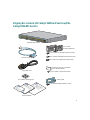
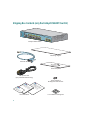
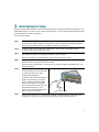
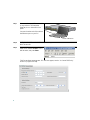
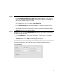
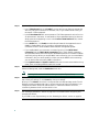
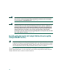
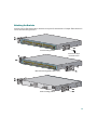
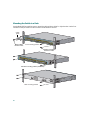
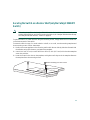
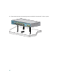
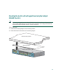
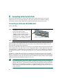
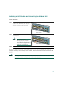
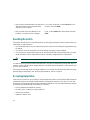
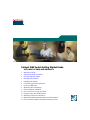
Catalyst 3560 Switch Getting Started Guide
INCLUDING LICENSE AND WARRANTY
1
2
3
4
5
6
7
8
9
10
11
12
13
14
About this Guide
Taking Out What You Need
Running Express Setup
Managing the Switch
Installing the Switch
Connecting to the Switch Ports
In Case of Difficulty
Obtaining Documentation
Documentation Feedback
Cisco Product Security Overview
Product Alerts and Field Notices
Obtaining Technical Assistance
Obtaining Additional Publications and Information
Cisco Limited Lifetime Hardware Warranty Terms
1 About this Guide
This guide provides instructions on how to use Express Setup to configure your Catalyst switch. Also
covered are switch management options, basic rack-mounting procedures, port and module
connections, power connection procedures, and troubleshooting help.
For additional installation and configuration information for Catalyst 3560 switches, see the
Catalyst 3560 documentation on Cisco.com. For system requirements, important notes, limitations,
open and resolved bugs, and last-minute documentation updates, see the release notes, also on
Cisco.com.
When using the online publications, refer to the documents that match the Cisco IOS software version
running on the switch. The software version is on the Cisco IOS label on the switch rear panel.
You can order printed copies of the manuals from the Cisco.com sites and from the telephone numbers
listed in the “Obtaining Documentation” section on page 26.
For translations of the warnings that appear in this publication, see the Regulatory Compliance and
Safety Information for the Catalyst 3560 Switch that accompanies this guide.
2 Taking Out What You Need
Follow these steps:
1. Unpack and remove the switch and the accessory kit from the shipping box.
2. Return the packing material to the shipping container, and save it for future use.
3. Verify that you have received the items shown on page 3. If any item is missing or damaged,
contact your Cisco representative or reseller for instructions. Some switch models might include
additional items that are not shown on page 3.
Equipment That You Supply to Run Express Setup
You need to supply this equipment to run Express Setup:
• PC
• Ethernet (Category 5) straight-through cable (as shown)
2
Shipping Box Contents (All Catalyst 3560 Switches Except the
Catalyst 3560-8PC Switch)
1
SYST
RPS
1X
STAT
DUPLX
SPEED
PoE
MODE
2
3
4
5
6
7
8
9
10
11
12
13
14
15
16
17
15X 17X
18
19
20
21
22
23
2X
24
25
26
27
28
29
30
31
32
33
31X 33X
16X
34
35
36
37
38
39
40
18X
41
42
43
44
45
46
47
Catalyst 3560
G SERIES PoE-
48
48
47X
32X 34X
49
51
48X
50
52
Catalyst 3560 switch
Two 19-inch
mounting brackets
Four number-12 Phillips machine screws
Four number-8 Phillips truss-head screws
Console cable
Six number-8 Phillips flat-head screws
Connector cover for redundant
power system (RPS)
AC power cord
Two number-4 pan-head screws
Four rubber mounting feet
Cable guide
e
nc
ia on
pl ti
a
om rm
h
C o
itc
y Inf
w
or y e S
at et th 0
ul af for 56
eg S
t3
R nd
ys
a
al
at
C
p
hi
rs
ne rd
w ca
n
co O io
is ct at
C u str
d gi
ro e
P R
h
itc
w de
S ui
0 G
56 ed
t 3 art
ys t
al S
at ng
C tti
e
G
One black Phillips machine screw
Documentation
3
Shipping Box Contents (only the Catalyst 3560-8PC Switch)
SYST
STAT
DPLX
SPD
PoE
CONSOL
E
1x
2x
3x
4x
MODE
5x
6x
7x
8x
Catalyst 35
60 SERIES Po
E-8
1
Catalyst 3560 switch
Mounting magnet
Console cable
Screw template
AC power cord
(AC-powered switches only)
Three number-8
Phillips pan-head screws
e
nc
ia on
pl ati
om m
h
r
C o
itc
y Inf
e Sw
or
y
at et th 0
ul af for 56
eg S
t3
R nd
ys
a
al
at
C
h
itc
w de
S ui
0 G
56 ed
t 3 art
ys t
al S
at ng
C tti
e
G
p
hi
rs
ne rd
w ca
n
co O io
is ct at
C u str
d gi
ro e
P R
Documentation
4
Four rubber mounting feet
3 Running Express Setup
When you first set up the switch, you should use Express Setup to enter the initial IP information. This
enables the switch to connect to local routers and the Internet. You can then access the switch through
the IP address for further configuration.
To run Express Setup:
Step 1
Make sure that nothing is connected to the switch.
During Express Setup, the switch acts as a DHCP server. If your PC has a static IP address,
change your PC settings before you begin to temporarily use DHCP.
Step 2
Power the switch by connecting the supplied AC power cord to the switch power
connector and to a grounded AC outlet.
Step 3
When the switch powers on, it begins the power-on self-test (POST). During POST, the
LEDs blink while tests verify that the switch functions properly.
Wait for the switch to complete POST, which can take several minutes.
Step 4
Verify that POST has completed by confirming that the SYST LED remains green. If the
switch fails POST, the SYST LED turns amber.
POST errors are usually fatal. Contact your Cisco technical support representative if your
switch fails POST.
Step 5
Press and hold the Mode button for
3 seconds. When all of the LEDs left
of the Mode button turn green,
release the Mode button.
If the LEDs left of the Mode button
begin to blink after you press the
button, release it. Blinking LEDs
mean that the switch has already
been configured and cannot go into
Express Setup mode. For more
information, see the “Resetting the
Switch” section on page 24.
Step 6
1
SYST
RPS
2
1X
STAT
DUPLX
SPEED
PoE
MODE
3
4
5
6
7
8
9
10
11
12
13
14
15
16
15X
2X
16X
Mode button
Verify that the switch is in Express Setup mode by confirming that all LEDs left of the
Mode button are green. (On some models, the RPS and PoE LEDs remain off.)
5
Step 7
Connect a Category 5 Ethernet cable
to any 10/100 or 10/100/1000
Ethernet port on the switch front
panel.
1
SYST
RPS
1X
STAT
DUPLX
SPEED
PoE
MODE
2
3
4
5
6
7
8
9
10
11
12
13
14
15
16
17
15X 17X
2X
18
19
20
21
22
23
24
25
26
27
28
29
30
31
32
33
31X 33X
16X
18X
34
35
36
37
38
39
40
41
42
43
44
45
46
47
Catalyst 3560G
48
SERIES
PoE-48
47X
32X 34X
49
51
Connect the other end of the cable to
the Ethernet port on your PC.
48X
50
52
DHCP-enabled PC
Step 8
Verify that the LEDs on both Ethernet ports are green.
Wait 30 seconds.
Step 9
Start a web browser on your PC.
Enter the IP address 10.0.0.1 in the
web browser, and press Enter.
The Express Setup page appears. If it does not appear, see the “In Case of Difficulty”
section on page 23 for help.
6
Step 10
Enter this information in the Network Settings fields:
• In the Management Interface (VLAN ID) field, the default is 1. Enter a new VLAN ID
only if you want to change the management interface through which you manage the
switch. The VLAN ID range is 1 to 1001.
• In the IP Address field, enter the IP address of the switch. In the IP Subnet Mask field,
click the drop-down arrow, and select an IP Subnet Mask.
• In the Default Gateway field, enter the IP address for the default gateway (router).
• Enter your password in the Switch Password field. The password can be from 1 to 25
alphanumeric characters, can start with a number, is case sensitive, allows embedded
spaces, but does not allow spaces at the beginning or end. In the Confirm Switch
Password field, enter your password again.
Step 11
(Optional) You can enter the Optional Settings information now or enter it later by using
the device manager interface:
• In the Host Name field, enter a name for the switch. The host name is limited to 31
characters. Embedded spaces are not allowed.
• Enter the date, time, and time zone information in the System Date, System Time, and
Time Zone fields. Click Enable to enable daylight saving time.
Step 12
(Optional) Click the Advanced Settings tab on the Express Setup window, and enter the
advanced settings now or enter them later by using the device manager interface.
7
Step 13
(Optional) Enter this information in the Advanced Setting fields:
• In the Telnet Access field, click Enable if you are going to use Telnet to manage the
switch by using the command-line interface (CLI). If you enable Telnet access, you
must enter a Telnet password.
• In the Telnet Password field, enter a password. The Telnet password can be from 1 to
25 alphanumeric characters, is case sensitive, allows embedded spaces, but does not
allow spaces at the beginning or end. In the Confirm Telnet Password field, re-enter
the Telnet password.
• In the SNMP field, click Enable to enable Simple Network Management Protocol
(SNMP). Enable SNMP only if you plan to manage switches by using
CiscoWorks 2000 or another SNMP-based network-management system.
• If you enable SNMP, you must enter a community string in the SNMP Read
Community field, the SNMP Write Community field, or both. SNMP community
strings authenticate access to MIB objects. Embedded spaces are not allowed in SNMP
community strings. When you set the SNMP read community, you can access SNMP
information, but you cannot modify it. When you set the SNMP write community,
you can both access and modify SNMP information.
• In the System Contact and System Location fields, enter a contact name and the wiring
closet, floor, or building where the switch is located.
Step 14
(Optional) You can enable Internet Protocol version 6 (IPv6) on the switch. From the
Advanced Settings tab, check the Enable IPv6 check box.
Note
Step 15
Enabling IPv6 restarts the switch when you complete Express Setup.
To complete Express Setup, click Submit from the Basic Settings or the Advanced Settings
tab to save your settings, or click Cancel to clear your settings.
When you click Submit, the switch is configured and exits Express Setup mode. The PC
displays a warning message and tries to connect with the new switch IP address. If you
configured the switch with an IP address that is in a different subnet from the PC,
connectivity between the PC and the switch is lost.
Step 16
Disconnect the switch from the PC, and install the switch in your production network. See
the “Managing the Switch” section on page 9 for information about configuring and
managing the switch.
If you need to rerun Express Setup, see the “Resetting the Switch” section on page 24.
8
Refreshing the PC IP Address
After you complete Express Setup, you should refresh the PC IP address.
For a dynamically assigned IP address, disconnect the PC from the switch, and reconnect it to the
network. The network DHCP server assigns a new IP address to the PC.
For a statically assigned IP address, change it to the previously configured IP address.
4 Managing the Switch
After completing Express Setup and installing the switch in your network, use the device manager or
other management options described in this section for further configuration.
Using the Device Manager
You can manage the switch by using the device manager that is in the switch memory. This is a web
interface that offers quick configuration and monitoring. You can access the device manager from
anywhere in your network through a web browser.
Follow these steps:
1. Start a web browser on your PC or workstation.
2. Enter the switch IP address in the web browser, and press Enter. The device manager page appears.
3. Use the device manager to perform basic switch configuration and monitoring. Refer to the device
manager online help for more information.
4. For more advanced configuration, install Cisco Network Assistant as described in the next section.
Downloading Cisco Network Assistant
Cisco Network Assistant is a free software program that you download from Cisco.com and run on
your PC. Network Assistant offers advanced options for configuring and monitoring multiple devices,
including switches, switch clusters, switch stacks, routers, and access points. Network Assistant is
free—there is no charge to download, install, or use it.
Follow these steps:
1. Go to this Web address: http://www.cisco.com/go/NetworkAssistant
You must be a registered Cisco.com user, but you need no other access privileges.
2. Find the Network Assistant installer.
9
3. Download the Network Assistant installer, and run it. (You can run it directly from the Web if
your browser offers this choice.)
4. When you run the installer, follow the displayed instructions. In the final panel, click Finish to
complete the Network Assistant installation.
Refer to the Network Assistant online help and the getting started guide for more information.
Command-Line Interface
You can enter Cisco IOS commands and parameters through the CLI. Access the CLI either by
connecting your PC directly to the switch console port or through a Telnet session from a remote PC
or workstation.
Follow these steps:
1. Connect the supplied RJ-45-to DB-9 adapter cable to the standard 9-pin serial port on the PC.
Connect the other end of the cable to the console port on the switch.
2. Start a terminal-emulation program on the PC.
3. Configure the PC terminal emulation software for 9600 baud, 8 data bits, no parity, 1 stop bit,
and no flow control.
4. Use the CLI to enter commands to configure the switch. See the software configuration guide and
the command reference for more information.
Other Management Options
You can use SNMP management applications such as CiscoWorks Small Network Management
Solution (SNMS) and HP OpenView to configure and manage the switch. You also can manage it from
an SNMP-compatible workstation that is running platforms such as HP OpenView or SunNet
Manager.
The Cisco IE2100 Series Configuration Registrar is a network management device that works with
embedded CNS agents in the switch software. You can use IE2100 to automate initial configurations
and configuration updates on the switch.
See the “Accessing Help Online” section on page 24 for a list of supporting documentation.
10
5 Installing the Switch
Depending on the switch model, you can install the switch in a rack, on a wall, on or under a desk or
shelf, and with a magnet or rack-mount brackets. This section covers rack-, desk-, shelf-, and
magnet-mounting a switch. Depending on the switch, For alternate mounting procedures, see the
Catalyst 3560 Switch Hardware Installation Guide on Cisco.com.
Equipment That You Supply
You need this equipment to install the switch:
• Number-2 Phillips screwdriver
• Drill with a #27 drill bit (0.144-inch [3.7 mm])
Note
A drill is required if you are securing the Catalyst 3560-8PC switch to a desk or a wall.
Before You Begin
When determining where to install the switch, verify that these guidelines are met:
• Airflow around the switch and through the
vents is unrestricted.
Note
We strongly recommend that you allow
at least 3 inches (7.6 cm) of clearance
around the ventilation openings.
• Temperature around the switch does not
exceed 113˚F (45˚C).
• Humidity around the switch does not exceed
85 percent.
• Do not place any items on the top of the
Catalyst 3560-8PC switch.
• The heatsinks and the bottom of the
Catalyst 3560-8PC switch might be hot to
the touch if the switch is operating at its
maximum temperature 113˚F (45˚C) and is in
an environment that exceeds normal room
temperature (such as in a closet, in a cabinet,
or in a closed or multirack assembly).
• Allow at least 1.75 inches (4 cm) of clearance
above each Catalyst 3560-8PC switch in the
rack.
• Altitude at the installation site is not greater
than 10,000 feet.
11
• When placing the Catalyst 3560-8PC switch
on a flat horizontal surface without the
magnet, we strongly recommend that you
attach the rubber feet to the switch. Doing so
helps prevent airflow restriction and
overheating.
• Do not stack switches or place
Catalyst 3560-8PC switches side-by-side,
unless they are separated all around by at
least 3 inches (7.6 cm) of clearance from each
other.
• Do not wall-mount the Catalyst 3560-8PC
switch with its front panel facing up or to the
side. We recommend wall-mounting the
switch with its front panel facing down to
prevent airflow restriction and to provide
easier access to the cables.
• Clearance to the switch front and rear panels
meets these conditions:
– Front-panel LEDs can be easily read.
– Access to ports is sufficient for
unrestricted cabling.
– AC power cord can reach from the AC
power outlet to the connector on the
switch rear panel.
• Cabling is away from sources of electrical
noise, such as radios, power lines, and
fluorescent lighting fixtures.
• For 10/100 ports and 10/100/1000 ports, the
cable length from a switch to an attached
device cannot exceed 328 feet (100 meters).
• For cable lengths for small form-factor
pluggable (SFP) modules, see the
documentation that shipped with the
module.
Installation Warning Statements
This section includes the basic installation warning statements. Translations of these warning
statements appear in the Regulatory Compliance and Safety Information for the Catalyst 3560 Switch
document that shipped with the switch.
Warning
Only trained and qualified personnel should be allowed to install, replace, or service this
equipment. Statement 148
Warning
To prevent the switch from overheating, do not operate it in an area that exceeds the
maximum recommended ambient temperature of 113˚F (45˚C). To prevent airflow
restriction, allow at least 3 inches (7.6 cm) of clearance around the ventilation openings.
Statement 17B
12
Warning
Installation of the equipment must comply with local and national electrical codes.
Statement 1074
Warning
To prevent bodily injury when mounting or servicing this unit in a rack, you must take
special precautions to ensure that the system remains stable. The following guidelines
are provided to ensure your safety:
• This unit should be mounted at the bottom of the rack if it is the only unit in the rack.
• When mounting this unit in a partially filled rack, load the rack from the bottom to the top
with the heaviest component at the bottom of the rack.
• If the rack is provided with stabilizing devices, install the stabilizers before mounting or
servicing the unit in the rack. Statement 1006
Warning
This equipment is intended to be grounded. Ensure that the host is connected to earth
ground during normal use. Statement 39
Warning
If a redundant power system (RPS) is not connected to the switch, install an RPS
connector cover on the back of the switch. Statement 265
Warning
Class 1 laser product. Statement 1008
13
Warning
For connections outside the building where the equipment is installed, the following
ports must be connected through an approved network termination unit with integral
circuit protection: 10/100/1000 Ethernet. Statement 1044
Warning
Voltages that present a shock hazard may exist on Power over Ethernet (PoE) circuits if
interconnections are made using uninsulated exposed metal contacts, conductors, or
terminals. Avoid using such interconnection methods, unless the exposed metal parts
are located within a restricted access location and users and service people who are
authorized within the restricted access location are made aware of the hazard. A
restricted access area can be accessed only through the use of a special tool, lock and
key or other means of security. Statement 1072
Rack-Mounting the Switch (All Catalyst 3560 Switches Except the
Catalyst 3560-8PC Switch)
Note
This section applies to all Catalyst 3560 switches except the Catalyst 3560-8PC switch. For
installation information for the Catalyst 3560-8PC switch, see “Securing the Switch on a Desk
or Shelf (only the Catalyst 3560-8PC Switch)” section on page 17 and “Mounting the Switch
with a Magnet Panel (only the Catalyst 3560-8PC Switch)” section on page 19.
This section covers basic 19-inch rack-mounting. As an example, all the illustrations show the
Catalyst 3560G-48PS switch. You can install and connect other Catalyst 3560 switches except the
Catalyst 3560-8PC switch as shown in these illustrations.
14
Attaching the Brackets
Use four Phillips flat-head screws to attach the long side of the brackets to Catalyst 3560 switches in
one of three mounting positions.
1
SYST
RPS
2
3
4
1X
5
6
7
8
9
10
11
STAT
DUPLX
SPEED
PoE
12
13
14
15
16
17
18
19
20
15X 17X
MODE
21
22
23
24
25
26
2X
27
28
29
30
31
32
33
34
35
36
31X 33X
37
38
39
40
16X 18X
41
42
43
44
45
46
47
Catalyst 3560
G SERIES PoE-
48
48
47X
32X 34X
49
51
50
48X
52
Front-mounting position
Number-8 Phillips
flat-head screws
1
SYST
RPS
1X
STAT
DUPLX
SPEED
PoE
MODE
2
3
4
5
6
7
8
9
10
11
12
13
14
15
16
17
15X 17X
2X
18
19
20
21
22
23
24
25
26
27
28
29
30
31
32
33
31X 33X
34
35
36
37
38
39
40
16X 18X
41
42
43
44
45
46
47
Catalyst 3560
G SERIES PoE-
48
48
47X
32X 34X
49
51
48X
50
52
Mid-rack-mounting position (telco rack)
CONSO
LE
DC INPU
TS FOR
REMOTE
POWER
SUPPLY
SPECIFI
ED IN
MANUAL
Rear-mounting position
15
Mounting the Switch in a Rack
Use the black Phillips machine screw to attach the cable guide to the left or right bracket. Use the four
number-12 Phillips machine screws to attach the brackets to the rack.
Cable
guide
1
SYST
RPS
2
3
1X
4
5
6
7
8
9
10
11
STAT
DUPLX
SPEED
PoE
12
13
14
15
16
17
18
19
15X 17X
MODE
20
21
22
23
24
25
26
2X
27
28
29
30
31
32
33
34
35
31X 33X
36
37
38
39
40
41
16X 18X
42
43
44
45
46
47
Catalyst 3560
G SERIES PoE-
48
48
47X
32X 34X
49
51
48X
50
52
Black Phillips
machine screw
Front-mounting position
Number-12 Phillips
machine screws
1
SYST
RPS
1X
STAT
DUPLX
SPEED
PoE
MODE
2
3
4
5
6
7
8
9
10
11
12
13
14
15
16
17
15X 17X
18
19
20
21
22
23
24
25
2X
26
27
28
29
30
31
32
33
34
35
31X 33X
16X 18X
36
37
38
39
40
41
42
43
44
45
46
47
Catalyst 3560
G SERIES PoE-
48
48
47X
32X 34X
49
51
48X
50
52
Mid-rack-mounting position (telco rack)
CONSOL
E
DC INPU
TS FOR
REMOTE
POWER
SUPPLY
SPECIFI
ED IN
MANUAL
Rear-mounting position
16
Securing the Switch on a Desk or Shelf (only the Catalyst 3560-8PC
Switch)
Note
This section is specific to the Catalyst 3560-8PC switch. For installation information for other
Catalyst 3560 switches, see “Rack-Mounting the Switch (All Catalyst 3560 Switches Except
the Catalyst 3560-8PC Switch)” section on page 14.
To place the switch on a desk without using the mounting screws, simply attach the four rubber feet
on the bottom panel of the switch.
To secure the switch on top of or under a desk or a shelf, or on a wall, use the mounting template and
three mounting screws. Follow these steps:
1. Position the screw template on the mounting surface with the two side-by-side slots forward. Peel
the adhesive strip off the bottom, and attach the template.
2. Use a 0.144-inch (3.7 mm) or a #27 drill bit to drill a 1/2-inch (12.7 mm) hole in the three template
screw slot positions.
3. Insert the screws in the slots on the template, and tighten until they touch the template. Remove
the template from the mounting surface.
Number-8 Phillips pan-head screws
Mounting template
17
4. Place the switch onto the mounting screws, and slide it forward until it locks in place.
SYST
STAT
DPLX
SPD
PoE
CONSOLE
MODE
1x
2x
3x
4x
5x
6x
7x
8x
Catalyst 35
60 SERIES Po
E-8
1
18
Mounting the Switch with a Magnet Panel (only the Catalyst
3560-8PC Switch)
Note
This section only applies to the Catalyst 3560-8PC switch. For installation information for all
other Catalyst 3560 switches, see “Rack-Mounting the Switch (All Catalyst 3560 Switches
Except the Catalyst 3560-8PC Switch)” section on page 14.
Follow these steps:
1. Position the mounting magnet on the mounting surface.
2. Place the bottom of the switch on the mounting magnet.
Metal mounting surface
Mounting magnet
Switch bottom panel
1
8x
7x
6x
5x
4x
SPD
STAT
DPLX
SYST
SYST
19
3x
2x
E
CONSOL
1x
E-8
60 SERIES Po
Catalyst 35
6 Connecting to the Switch Ports
This section describes how to connect to the switch ports, the SFP module ports, and to the
dual-purpose ports. It also describes how to verify your connections. For additional cabling
information, see the Catalyst 3560 Switch Hardware Installation Guide on Cisco.com.
Connecting to 10/100 and 10/100/1000 Ports
Follow these steps:
Step 1
Step 2
When you connect to servers,
workstations, IP phones, wireless access
points, and routers, insert a
straight-through, twisted four-pair,
Category 5 cable in a switch 10/100 or
10/100/1000 port. Use a crossover,
twisted four-pair, Category 5 cable when
you connect to other switches, hubs, or
repeaters.
1
SYST
RPS
1X
2
3
4
5
6
7
8
9
STAT
DUPLX
SPEED
PoE
MODE
10
11
12
13
14
15
16
15X
2X
16X
10/100 or 10/100/1000 ports
Insert the other cable end into an RJ-45 connector on the other device.
The fixed ports on the Catalyst 3560 Power over Ethernet (PoE) switches provide PoE support for
devices compliant with IEEE 802.3af and also provide Cisco pre-standard PoE support for Cisco
IP Phones and Cisco Aironet Access Points.
Each of the Catalyst 3560-24PS switch 10/100 ports or the Catalyst 3560G-24PS switch 10/100/1000
ports can deliver up to 15.4 W of PoE. On the Catalyst 3560-48PS or 3560G-48PS switches, any 24
of the 48 10/100 or 10/100/1000 ports can deliver 15.4 W of PoE, or any combination of the ports
can deliver an average of 7.7 W of PoE at the same time, up to a maximum switch power output of
370 W.
By default, a Catalyst 3560 switch PoE port automatically provides power when a valid powered
device is connected to it. For information about configuring and monitoring PoE ports, see the switch
software configuration guide. For information about troubleshooting PoE problems, see the Catalyst
3560 Switch Hardware Installation Guide on Cisco.com.
Note
20
For simplified cabling, the automatic medium-dependent interface crossover (auto-MDIX)
feature is enabled by default on the switch. With auto-MDIX enabled, the switch detects the
required cable type for copper Ethernet connections and configures the interfaces accordingly.
Therefore, you can use either a crossover or a straight-through cable for connections to a
switch 10/100 or 10/100/1000 Ethernet port, regardless of the type of device on the other end
of the connection.
Installing an SFP Module and Connecting to a Module Port
Follow these steps:
Step 1
Grasp the module on the sides, and
insert it into the switch slot until you
feel the connector snap into place.
33
34
35
33X
36
37
38
39
40
41
42
43
44
45
46
47
Catalyst 35
60G SERIES
48
PoE-48
47X
34X
1
49
51
2
1
50
48X
52
2
SFP module
Step 2
Insert an appropriate cable into the
module port.
33
34
35
33X
Note
Step 3
If your switch has a
dual-purpose port, see the
“Connecting to a Dual-Purpose
Port” section on page 22 for
additional considerations.
36
37
38
39
40
41
42
43
44
45
46
47
Catalyst 35
60G SERIES
48
PoE-48
47X
1
34X
49
2
51
1
48X
50
2
52
SFP module port
Insert the other cable end into the other device.
For a list of supported modules, see the release notes on Cisco.com. For detailed instructions on
installing, removing, and connecting to SFP modules, see the documentation that came with the SFP
module.
Caution
Removing and installing an SFP module can shorten its useful life. Do not remove and
insert SFP modules more often than is absolutely necessary.
21
Connecting to a Dual-Purpose Port
For information about using the SFP module port, see the “Installing an SFP Module and Connecting
to a Module Port” section on page 21.
Follow these steps:
Insert either an RJ-45 connector to the
10/100/1000 port, or install an SFP module
into the SFP module slot, and connect a cable
to the SFP module port.
Only one port can be active at a time. If both
ports are connected, the SFP module port has
priority. The priority setting is not
configurable.
Step 2
5x
6x
7x
8x
Catalyst 35
60 SERIES Po
E-8
1
210092
Step 1
Insert the other cable end into the other device.
Verifying Port Connectivity
After you connect to the switch port, the port LED turns amber while the switch establishes a link.
This process takes about 30 seconds, and then the LED turns green when the switch and the target
device have an established link. If the LED is off, the target device might not be turned on, there might
be a cable problem, or there might be a problem with the adapter installed in the target device. See the
“In Case of Difficulty” section on page 23 for information about online assistance.
22
7 In Case of Difficulty
If you experience difficulty, help is available here and on Cisco.com. This section includes Express
Setup troubleshooting, how to reset the switch, how to access help online, and where to find more
information.
Troubleshooting Express Setup
If Express Setup does not run, or if the Express Setup page does not appear in your browser:
• Did you verify that POST successfully ran
before starting Express Setup?
If not, make sure that only the SYST and STAT
LEDs are green before pressing the Mode button
to enter the Express Setup mode.
• Did you press the Mode button while the
switch was still running POST?
If yes, wait until POST completes. Power cycle the
switch. Wait until POST completes. Confirm that
the SYST and STAT LEDs are green. Press the
Mode button to enter Express Setup mode.
• Did you try to continue without confirming
that the switch was in Express Setup mode?
Verify that all LEDs left of the Mode button are
green. (On some models, the RPS LED is off.) If
necessary, press the Mode button to enter Express
Setup mode.
• Does your PC have a static IP address?
If yes, change your PC settings to temporarily use
DHCP before connecting to the switch.
• Did you connect a crossover cable instead of If yes, connect a straight-through cable to an
a straight-through Ethernet cable between a Ethernet port on the switch and the PC. Wait 30
switch port and the Ethernet port of the PC? seconds before entering 10.0.0.1 in the browser.
• Did you connect the Ethernet cable to the
console port instead of to a 10/100 or
10/100/1000 Ethernet port on the switch?
If yes, disconnect from the console port. Connect
to an Ethernet port on the switch and the PC.
Wait 30 seconds before entering 10.0.0.1 in the
browser.
23
• Did you wait 30 seconds after connecting the If not, wait 30 seconds, re-enter 10.0.0.1 in the
switch and the PC before entering the IP
browser, and press Enter.
address in your browser?
• Did you enter the wrong address in the
browser, or is there an error message?
If yes, re-enter 10.0.0.1 in the browser, and press
Enter.
Resetting the Switch
This section describes how to reset the switch by rerunning Express Setup. These are reasons why you
might want to reset the switch:
• You installed the switch in your network and cannot connect to it because you assigned the wrong
IP address.
• You want to clear all configuration from the switch and assign a new IP address.
• You are trying to enter Express Setup mode, and the switch LEDs start blinking when you press
the Mode button, which means that the switch is already configured with IP information.
Caution
Resetting the switch deletes the configuration and reboots the switch.
To reset the switch, press and hold the Mode button. The switch LEDs begin blinking after about 3
seconds. Continue holding down the Mode button. The LEDs stop blinking after 7 more seconds, and
then the switch reboots.
The switch now behaves like an unconfigured switch. You can enter the switch IP information by using
Express Setup as described in the “Running Express Setup” section on page 5.
Accessing Help Online
First look for a solution to your problem in the troubleshooting section of the Catalyst 3560 Hardware
Installation Guide or the Catalyst 3560 Software Configuration Guide on Cisco.com. You can also
access the Cisco Technical Support and Documentation website for a list of known hardware problems
and extensive troubleshooting documentation, including:
• Factory defaults and password recovery
• Recovery from corrupted or missing software
• Switch port problems
• Network interface cards
24
• Troubleshooting tools
• Field notices and security advisories
Follow these steps:
1. Open your browser, and go to http://www.cisco.com/.
2. Click Technical Support.
3. Click Product Support > Switches > LAN and ATM Switches > Catalyst 3560 Series Switches >
Troubleshooting.
4. Click the subject that addresses the problem that you are experiencing.
For More Information
For more information about the switch, see these documents on Cisco.com:
• Release Notes for the Catalyst 3750, 3560, 2970, and 2960 Switches (not orderable but available
on Cisco.com). Before installing, configuring, or upgrading the switch, refer to the release notes
on Cisco.com for the latest information.
• Catalyst 3560 Switch Hardware Installation Guide (not orderable, but available on Cisco.com).
This guide provides complete hardware descriptions and detailed installation procedures.
• Regulatory Compliance and Safety Information for the Catalyst 3560 Switch (order number
DOC-7816665=). This guide contains agency approvals, compliance information, and translated
warning statements.
• Catalyst 3560 Switch Software Configuration Guide (order number DOC-7816156=). This guide
provides a product overview and detailed descriptions and procedures of the switch software
features.
• Catalyst 3560 Switch Command Reference (order number DOC-7816155=). This reference
provides detailed descriptions of the Cisco IOS commands specifically created or modified for the
switch.
• Catalyst 3750, 3560, 3550, 2970, and 2960 Switch System Message Guide (order number
DOC-7816154=). This guide provides descriptions of the system messages specifically created or
modified for the switch.
• Device manager online help (available on the switch)
25
8 Obtaining Documentation
Cisco documentation and additional literature are available on Cisco.com. This section explains the
product documentation resources that Cisco offers.
Cisco.com
You can access the most current Cisco documentation at this URL:
http://www.cisco.com/techsupport
You can access the Cisco website at this URL:
http://www.cisco.com
You can access international Cisco websites at this URL:
http://www.cisco.com/public/countries_languages.shtml
Product Documentation DVD
The Product Documentation DVD is a library of technical product documentation on a portable
medium. The DVD enables you to access installation, configuration, and command guides for
Cisco hardware and software products. With the DVD, you have access to the HTML documentation
and some of the PDF files found on the Cisco website at this URL:
http://www.cisco.com/univercd/home/home.htm
The Product Documentation DVD is created and released regularly. DVDs are available singly or by
subscription. Registered Cisco.com users can order a Product Documentation DVD (product number
DOC-DOCDVD= or DOC-DOCDVD=SUB) from Cisco Marketplace at the Product Documentation
Store at this URL:
http://www.cisco.com/go/marketplace/docstore
Ordering Documentation
You must be a registered Cisco.com user to access Cisco Marketplace. Registered users may order
Cisco documentation at the Product Documentation Store at this URL:
http://www.cisco.com/go/marketplace/docstore
If you do not have a user ID or password, you can register at this URL:
http://tools.cisco.com/RPF/register/register.do
26
9 Documentation Feedback
You can provide feedback about Cisco technical documentation on the Cisco Technical Support &
Documentation site area by entering your comments in the feedback form available in every online
document.
10 Cisco Product Security Overview
Cisco provides a free online Security Vulnerability Policy portal at this URL:
http://www.cisco.com/en/US/products/products_security_vulnerability_policy.html
From this site, you will find information about how to do the following:
• Report security vulnerabilities in Cisco products
• Obtain assistance with security incidents that involve Cisco products
• Register to receive security information from Cisco
A current list of security advisories, security notices, and security responses for Cisco products is
available at this URL:
http://www.cisco.com/go/psirt
To see security advisories, security notices, and security responses as they are updated in real time, you
can subscribe to the Product Security Incident Response Team Really Simple Syndication (PSIRT RSS)
feed. Information about how to subscribe to the PSIRT RSS feed is found at this URL:
http://www.cisco.com/en/US/products/products_psirt_rss_feed.html
Reporting Security Problems in Cisco Products
Cisco is committed to delivering secure products. We test our products internally before we release
them, and we strive to correct all vulnerabilities quickly. If you think that you have identified a
vulnerability in a Cisco product, contact PSIRT:
• For emergencies only — [email protected]
An emergency is either a condition in which a system is under active attack or a condition for
which a severe and urgent security vulnerability should be reported. All other conditions are
considered nonemergencies.
• For nonemergencies — [email protected]
27
In an emergency, you can also reach PSIRT by telephone:
• 1 877 228-7302
• 1 408 525-6532
Tip
We encourage you to use Pretty Good Privacy (PGP) or a compatible product (for example,
GnuPG) to encrypt any sensitive information that you send to Cisco. PSIRT can work with
information that has been encrypted with PGP versions 2.x through 9.x.
Never use a revoked encryption key or an expired encryption key. The correct public key to
use in your correspondence with PSIRT is the one linked in the Contact Summary section of
the Security Vulnerability Policy page at this URL:
http://www.cisco.com/en/US/products/products_security_vulnerability_policy.html
The link on this page has the current PGP key ID in use.
If you do not have or use PGP, contact PSIRT to find other means of encrypting the data before
sending any sensitive material.
11 Product Alerts and Field Notices
Modifications to or updates about Cisco products are announced in Cisco Product Alerts and
Cisco Field Notices. You can receive Cisco Product Alerts and Cisco Field Notices by using the
Product Alert Tool on Cisco.com. This tool enables you to create a profile and choose those products
for which you want to receive information.
To access the Product Alert Tool, you must be a registered Cisco.com user. (To register as a Cisco.com
user, go to this URL: http://tools.cisco.com/RPF/register/register.do) Registered users can access the
tool at this URL: http://tools.cisco.com/Support/PAT/do/ViewMyProfiles.do?local=en
12 Obtaining Technical Assistance
Cisco Technical Support provides 24-hour-a-day award-winning technical assistance. The
Cisco Technical Support & Documentation website on Cisco.com features extensive online support
resources. In addition, if you have a valid Cisco service contract, Cisco Technical Assistance Center
(TAC) engineers provide telephone support. If you do not have a valid Cisco service contract, contact
your reseller.
28
Cisco Technical Support & Documentation Website
The Cisco Technical Support & Documentation website provides online documents and tools for
troubleshooting and resolving technical issues with Cisco products and technologies. The website is
available 24 hours a day at this URL:
http://www.cisco.com/techsupport
Access to all tools on the Cisco Technical Support & Documentation website requires a Cisco.com
user ID and password. If you have a valid service contract but do not have a user ID or password, you
can register at this URL:
http://tools.cisco.com/RPF/register/register.do
Note
Use the Cisco Product Identification Tool to locate your product serial number before
submitting a request for service online or by phone. You can access this tool from the
Cisco Technical Support & Documentation website by clicking the Tools & Resources link,
clicking the All Tools (A-Z) tab, and then choosing Cisco Product Identification Tool from
the alphabetical list. This tool offers three search options: by product ID or model name; by
tree view; or, for certain products, by copying and pasting show command output. Search
results show an illustration of your product with the serial number label location highlighted.
Locate the serial number label on your product and record the information before placing a
service call.
Tip
Displaying and Searching on Cisco.com
If you suspect that the browser is not refreshing a web page, force the browser to update the
web page by holding down the Ctrl key while pressing F5.
To find technical information, narrow your search to look in technical documentation, not the
entire Cisco.com website. On the Cisco.com home page, click the Advanced Search link under
the Search box and then click the Technical Support & Documentation radio button.
To provide feedback about the Cisco.com website or a particular technical document, click
Contacts & Feedback at the top of any Cisco.com web page.
29
Submitting a Service Request
Using the online TAC Service Request Tool is the fastest way to open S3 and S4 service requests.
(S3 and S4 service requests are those in which your network is minimally impaired or for which you
require product information.) After you describe your situation, the TAC Service Request Tool
provides recommended solutions. If your issue is not resolved using the recommended resources, your
service request is assigned to a Cisco engineer. The TAC Service Request Tool is located at this URL:
http://www.cisco.com/techsupport/servicerequest
For S1 or S2 service requests, or if you do not have Internet access, contact the Cisco TAC by
telephone. (S1 or S2 service requests are those in which your production network is down or severely
degraded.) Cisco engineers are assigned immediately to S1 and S2 service requests to help keep your
business operations running smoothly.
To open a service request by telephone, use one of the following numbers:
Asia-Pacific: +61 2 8446 7411
Australia: 1 800 805 227
EMEA: +32 2 704 55 55
USA: 1 800 553 2447
For a complete list of Cisco TAC contacts, go to this URL:
http://www.cisco.com/techsupport/contacts
Definitions of Service Request Severity
To ensure that all service requests are reported in a standard format, Cisco has established severity
definitions.
Severity 1 (S1)—An existing network is “down” or there is a critical impact to your business
operations. You and Cisco will commit all necessary resources around the clock to resolve the
situation.
Severity 2 (S2)—Operation of an existing network is severely degraded, or significant aspects of your
business operations are negatively affected by inadequate performance of Cisco products. You and
Cisco will commit full-time resources during normal business hours to resolve the situation.
Severity 3 (S3)—Operational performance of the network is impaired while most business operations
remain functional. You and Cisco will commit resources during normal business hours to restore
service to satisfactory levels.
Severity 4 (S4)—You require information or assistance with Cisco product capabilities, installation, or
configuration. There is little or no effect on your business operations.
30
13 Obtaining Additional Publications and Information
Information about Cisco products, technologies, and network solutions is available from various
online and printed sources.
• The Cisco Online Subscription Center is the website where you can sign up for a variety of
Cisco e-mail newsletters and other communications. Create a profile and then select the
subscriptions that you would like to receive. To visit the Cisco Online Subscription Center, go
to this URL:
http://www.cisco.com/offer/subscribe
• The Cisco Product Quick Reference Guide is a handy, compact reference tool that includes brief
product overviews, key features, sample part numbers, and abbreviated technical specifications
for many Cisco products that are sold through channel partners. It is updated twice a year and
includes the latest Cisco channel product offerings. To order and find out more about the
Cisco Product Quick Reference Guide, go to this URL:
http://www.cisco.com/go/guide
• Cisco Marketplace provides a variety of Cisco books, reference guides, documentation, and logo
merchandise. Visit Cisco Marketplace, the company store, at this URL:
http://www.cisco.com/go/marketplace/
• Cisco Press publishes a wide range of general networking, training, and certification titles. Both
new and experienced users will benefit from these publications. For current Cisco Press titles and
other information, go to Cisco Press at this URL:
http://www.ciscopress.com
• Internet Protocol Journal is a quarterly journal published by Cisco Systems for engineering
professionals involved in designing, developing, and operating public and private internets and
intranets. You can access the Internet Protocol Journal at this URL:
http://www.cisco.com/ipj
• Networking products offered by Cisco Systems, as well as customer support services, can be
obtained at this URL:
http://www.cisco.com/en/US/products/index.html
• Networking Professionals Connection is an interactive website where networking professionals
share questions, suggestions, and information about networking products and technologies with
Cisco experts and other networking professionals. Join a discussion at this URL:
http://www.cisco.com/discuss/networking
31
• “What’s New in Cisco Documentation” is an online publication that provides information about
the latest documentation releases for Cisco products. Updated monthly, this online publication is
organized by product category to direct you quickly to the documentation for your products. You
can view the latest release of “What’s New in Cisco Documentation” at this URL:
http://www.cisco.com/univercd/cc/td/doc/abtunicd/136957.htm
• World-class networking training is available from Cisco. You can view current offerings at
this URL:
http://www.cisco.com/en/US/learning/index.html
14 Cisco Limited Lifetime Hardware Warranty Terms
There are special terms applicable to your hardware warranty and various services that you can use
during the warranty period. Your formal Warranty Statement, including the warranties and license
agreements applicable to Cisco software, is available on Cisco.com. Follow these steps to access and
download the Cisco Information Packet and your warranty and license agreements from Cisco.com.
1. Start your browser, and go to this URL:
http://www.cisco.com/univercd/cc/td/doc/es_inpck/cetrans.htm
The Warranties and License Agreements page appears.
2. To read the Cisco Information Packet, follow these steps:
a. Click the Information Packet Number field, and make sure that the part number
78-5235-03B0 is highlighted.
b. Select the language in which you would like to read the document.
c. Click Go.
The Cisco Limited Warranty and Software License page from the Information Packet appears.
d. Read the document online, or click the PDF icon to download and print the document in Adobe
Portable Document Format (PDF).
Note
You must have Adobe Acrobat Reader to view and print PDF files. You can download
the reader from Adobe’s website: http://www.adobe.com
3. To read translated and localized warranty information about your product, follow these steps:
a. Enter this part number in the Warranty Document Number field:
78-6310-02C0
b. Select the language in which you would like to view the document.
32
c. Click Go.
The Cisco warranty page appears.
d. Read the document online, or click the PDF icon to download and print the document in Adobe
Portable Document Format (PDF).
You can also contact the Cisco service and support website for assistance:
http://www.cisco.com/public/Support_root.shtml.
Duration of Hardware Warranty
A Cisco product hardware warranty is supported for as long as the original end user continues to own or
use the product, provided that the fan and power supply warranty is limited to five (5) years. In the event
of a discontinuance of product manufacture, the Cisco warranty support is limited to five (5) years from
the announcement of the discontinuance.
Replacement, Repair, or Refund Policy for Hardware
Cisco or its service center will use commercially reasonable efforts to ship a replacement part within ten
(10) working days after receipt of the Return Materials Authorization (RMA) request. Actual delivery
times can vary, depending on the customer location.
Cisco reserves the right to refund the purchase price as its exclusive warranty remedy.
To Receive a Return Materials Authorization (RMA) Number
Contact the company from whom you purchased the product. If you purchased the product directly from
Cisco, contact your Cisco Sales and Service Representative.
Complete the information below, and keep it for reference.
Company product purchased from
Company telephone number
Product model number
Product serial number
Maintenance contract number
33
34
35
Corporate Headquarters
Cisco Systems, Inc.
170 West Tasman Drive
San Jose, CA 95134-1706
USA
www.cisco.com
Tel: 408 526-4000
800 553-NETS (6387)
Fax: 408 526-4100
European Headquarters
Cisco Systems International BV
Haarlerbergpark
Haarlerbergweg 13-19
1101 CH Amsterdam
The Netherlands
www-europe.cisco.com
Tel: 31 0 20 357 1000
Fax: 31 0 20 357 1100
Americas Headquarters
Cisco Systems, Inc.
170 West Tasman Drive
San Jose, CA 95134-1706
USA
www.cisco.com
Tel: 408 526-7660
Fax: 408 527-0883
Asia Pacific Headquarters
Cisco Systems, Inc.
168 Robinson Road
#28-01 Capital Tower
Singapore 068912
www.cisco.com
Tel: +65 6317 7777
Fax: +65 6317 7799
Cisco Systems has more than 200 offices in the following countries. Addresses, phone numbers, and fax numbers are listed on the
Cisco Website at www.cisco.com/go/offices
Argentina • Australia • Austria • Belgium • Brazil • Bulgaria • Canada • Chile • China PRC • Colombia • Costa Rica • Croatia • Cyprus • Czech Republic • Denmark • Dubai, UAE
Finland • France • Germany • Greece • Hong Kong SAR • Hungary • India • Indonesia • Ireland • Israel • Italy • Japan • Korea • Luxembourg • Malaysia • Mexico
The Netherlands • New Zealand • Norway • Peru • Philippines • Poland • Portugal • Puerto Rico • Romania • Russia • Saudi Arabia • Scotland • Singapore
Slovakia • Slovenia • South Africa • Spain • Sweden • Switzerland • Taiwan • Thailand • Turkey • Ukraine • United Kingdom • United States • Venezuela • Vietnam • Zimbabwe
CCVP, the Cisco Logo, and the Cisco Square Bridge logo are trademarks of Cisco Systems, Inc.; Changing the Way We Work, Live, Play, and Learn
is a service mark of Cisco Systems, Inc.; and Access Registrar, Aironet, BPX, Catalyst, CCDA, CCDP, CCIE, CCIP, CCNA, CCNP, CCSP, Cisco, the
Cisco Certified Internetwork Expert logo, Cisco IOS, Cisco Press, Cisco Systems, Cisco Systems Capital, the Cisco Systems logo, Cisco Unity,
Enterprise/Solver, EtherChannel, EtherFast, EtherSwitch, Fast Step, Follow Me Browsing, FormShare, GigaDrive, GigaStack, HomeLink, Internet
Quotient, IOS, IP/TV, iQ Expertise, the iQ logo, iQ Net Readiness Scorecard, iQuick Study, LightStream, Linksys, MeetingPlace, MGX, Networking
Academy, Network Registrar, Packet, PIX, ProConnect, RateMUX, ScriptShare, SlideCast, SMARTnet, StackWise, The Fastest Way to Increase Your
Internet Quotient, and TransPath are registered trademarks of Cisco Systems, Inc. and/or its affiliates in the United States and certain other countries.
All other trademarks mentioned in this document or Website are the property of their respective owners. The use of the word partner does not imply
a partnership relationship between Cisco and any other company. (0609R)
© 2004-2006 Cisco Systems, Inc. All rights reserved.
Printed in the USA on recycled paper containing 10% postconsumer waste.
78-16660-04
DOC-7816660=