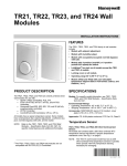
1
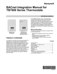
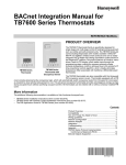
Zio®/Zio Plus LCD
Wall Modules
®
TR70, TR71, TR75 with Sylk Bus
OPERATING GUIDE
begins with “Initial Power-Up” on page 2, and the general
overview begins with “Operating the Zio Wall Module” on
page 19.
It is intended to guide you through the features and operation
of the TR70 Series as you interface with the programmable
controller and establish pre-programmed or custom
configurations.
LCD PANEL
SOFTKEYS (3)
APPLICATION
The Zio TR70 Series (TR70, TR70-H, TR71, TR71-H, TR75,
and TR75-H OS numbers) LCD Wall Modules provide an
operator interface for monitoring and adjusting parameters in
the wall module itself and in the programmable controller
(refer to the Honeywell Spyder® User’s Guide, form 63-2662,
or the ComfortPoint™ Programmable Controller User’s Guide,
form 63-2663, depending on the programmable controller
used) to which it is wired. The wall module may be customized
and supports both a contractor and a tenant user interface.
NOTE: This document illustrates the wall module configuration process using information from the Honeywell
Spyder User’s Guide (form 63-2662).
The wall module has a snap in mounting to a subbase that
may be mounted on a wall, on a standard utility conduit box, or
on a 60 mm wall outlet box. Wiring connections to the wall
module are made through a cutout in the back of the wall
module.
All models have a space temperature sensor, network bus
jack, and an LCD panel with three softkeys and two Up/Down
adjustment keys. Models with -H also include an onboard
humidity sensor.
PREFACE
This Operating Guide is intended to provide configuration
information (using the Niagara Workbench tool) and a general
overview of the TR70 Series operator interface. Configuration
UP/DOWN
ARROW KEYS
NETWORK BUS PORT (ON BOTTOM OF CASE)
M27344
Fig. 1. LCD Wall Module features.
Contents
Application ........................................................................
Preface .............................................................................
TR70 Series Features .......................................................
Compatibility .............................................................
Initial Power-Up .................................................................
Setup and Configuration ...................................................
Initial Setup and Configuration ..................................
Selecting the Wall Module .........................................
TR71/TR75 Labels ....................................................
Navigation and Memory Usage .................................
Wall Module Configuration ........................................
General Settings ...................................................
Categories and Parameters ..................................
Home Screen Options ...........................................
Occupancy and Override ......................................
Fan Command .......................................................
System Status and Command ..............................
Schedule/Time ......................................................
Password ...............................................................
Preview ..................................................................
Completing the Setup and Configuration ..................
Operating the Zio Wall Module .........................................
Contractor Mode Operation ......................................
Tenant Mode Operation ............................................
63-2719-03
1
1
2
2
2
3
3
3
3
3
4
5
5
9
10
12
13
14
15
16
17
19
19
22
ZIO®/ZIO PLUS LCD WALL MODULES
TR70 SERIES FEATURES
Likewise, a TR71 can be replaced by another TR71 or TR75
without reprogramming required. A TR75 can only be
replaced with a TR75 where no reprogramming is desired.
Table 1. TR70 Series Features.
Zio
TR70
Features
INITIAL POWER-UP
Zio Zio Plus
TR71 TR75
Scheduling
IMPORTANT
1. Make sure the TR70 Series wall module is properly
mounted and properly wired and connected to the
programmable controller.
2. Refer to the Zio™ LCD Wall Modules TR70 Series
with Sylk™ Bus – Installation Instructions, form 620271, for specific installation requirements.
x
Parameter Memory (bytes)
1K
2K
4.9K
Up to four Zios on Sylk
x*
x
x
Enumerated Values
x
x
Setpoint Limits as NVs – linking
now possible
x
x
System and Fan command as NVs
x
x
Password protection
x
x
Firmware version/model visible on
display
x
x
0.5 and 5 value increments
x
x
"-" and "/" characters in parameter
names
x
x
Upon initial power-up before configuring the wall module, the
LCD screen displays the phrase “PLEASE LOAd” in the Label/
Value area of Fig. 2. This phrase alternates with any onboard
sensor display such as temperature. The TR71/TR75 also
display the firmware revision number, model number and Sylk
bus address as shown in Fig. 27.
Fig. 2 illustrates all the possible LCD Wall Module display
elements. Only those elements pertinent to the current
configuration and status actually display.
* A maximum of four Zios may be wired on a single Sylk bus,
with no more than one TR70 per bus.
SYSTEM
STATUS
AREA
Compatibility
LABEL/
VALUE
(8 CHAR.)
OVERRIDE
INFORMATION
The TR70 Series LCD Wall Modules operate with the Sylk
Enhanced Spyder Controller or the Sylk Enhanced
ComfortPoint Controller. The table below provides
compatibility information for each model. The TR71/TR75 can
replace a TR70 in an installation where an upgrade to WEBsAX or Spyder or reprogramming is not desired. Features like
scheduling, additional memory, etc. will not be available.
CURRENT
DISPLAYED
VALUE
ENGINEERING
UNITS
FAN
INFORMATION
OCCUPANCY
STATUS
SOFTKEY
LABELS
M27353
Fig. 2. TR70 Series Wall Module - LCD screen.
Table 2. Compatibility.*
Scenari Spyde Spyder Compatible
o
r Tool Firmware
?
Zio TR70/TR71/TR75*
What can be done?
1
5.200
+
Latest
YES
New TR71/75 functionality Ideal scenario
available (if TR70 is present,
then only TR70
functionality)
2
5.200
+
Old
YES
Only with TR70 functionality Spyder firmware can be upgraded (this becomes scenario
(TR71/75 can be used, but 1)
only TR70 functionality will
be there)
3
< 5.18 Latest
NO
Tool does not recognize the Spyder Tool can be upgraded (this becomes scenario 1)
new Spyder
Spyder firmware can be downgraded (this becomes
scenario 4)
4
< 5.18 Old
YES
Only with TR70 functionality
(TR71/75 can be used, but
only TR70 functionality will
be there)
Both Spyder firmware and Tool can be upgraded (this
becomes scenario 1)
Spyder Tool can be upgraded (this becomes scenario 2)
Spyder firmware can be upgraded (this becomes scenario
3)
* The new Spyder tool (6.0 or greater) assumes the latest Spyder capability. At download, the Tool reads the brand/model of the
connected Spyder and determines if it matches the features on the wire sheet. If old or new Spyder is programmed with aTR70,
it can be physically replaced with a TR71 or TR75.
63-2719—03
2
ZIO®/ZIO PLUS LCD WALL MODULES
SETUP AND CONFIGURATION
TR71/TR75 Labels
The TR71/TR75 allows the use of the following special
characters in label fields such as Categories and Parameter
Names: underscore ( _ ) to insert a space, hyphen ( - ), and
forward slash ( / ). The TR70 allows use of the underscore
( _ ) character to insert a space.
Initial Setup and Configuration
Once the wall module is wired to the controller, you configure
the wall module using the PC-based, Niagara Workbench
Tool. Refer to the applicable programmable controller User’s
Guide. (Refer to the Honeywell Spyder User’s Guide, form 632662, or the ComfortPoint Programmable Controller User’s
Guide, form 63-2663, depending on the programmable
controller used.) This tool is used to configure the wall module
for either the Spyder or the ComfortPoint programmable
controller.
Navigation and Memory Usage
The Honeywell Spyder Tool uses an intuitive, window-based
interface. A Help button on each screen provides assistance
with any entry or process.
IMPORTANT
Use the Help button to display context specific help
for the current window or pane display. See the lower
left corner of Fig. 6 on page 5 for the location of the
Help button.
Confirm Bus Address Setting
Check to ensure that the Wall Module’s bus address dial
(located on the back of the module) is set to match the setting
in the configuration tool. TR70 models can be set from 1–5
and TR71/TR75 can be set from 1–10 (0 on the Zio address
dial is equal to 10 in the configuration tool). The address must
be different for each device on the Sylk bus. Up to four Zios
per Spyder are allowed with any combination of TR71/TR75s
and up to three Zios are allowed if one or more is a TR70
model.
NOTE: At any time, clicking the Preview button (lower left of
main window, see Fig. 6 on page 5) displays the
updated wall module LCD as a pop-up. Preview simulates the actual wall module interface and allows
you to verify the operation of the current configuration of the wall module. See “Preview” on page 16.
Selecting the Wall Module
Navigation
You will use the Sylk S-Bus wall module function block from
the Palette’s Built-In folder (see Fig. 3). This configuration has
nothing programmed except the room temperature parameter
and occupancy status.
1. Add the Sylk S-Bus Wall Module function block to the
wire sheet via a left click, drag, and drop. See callout 1
in Fig. 3.
2. Right click on the S-Bus Wall Module function block to
open the Configuration Properties menu. See callout 2
in Fig. 3.
3. Left click on the title, Configuration Properties. This
action starts the Configuration Wizard. The Configuration Wizard steps (see Fig. 5 on page 4) are used to
configure the wall module.
Table 3 describes the navigation buttons at the bottom of the
wall module window. See the bottom of Fig. 7 on page 5 for
the location of these buttons. Buttons are greyed when
unavailable.
Table 3. Navigation Buttons.
Item
Help
Save to For new custom configurations and standard
Library configurations.
Clicking the button opens the Save to Library
screen (shown in Fig. 25 on page 17). This action
allows you to save the entire current wall module
configuration.
The Save to Library button is disabled until you
change the configuration (application). After a
change is made, you can save the new
configuration into the library under a new name.
RIGHT CLICK
SBusWallModule
When clicked, this button provides context sensitive
help for the currently selected item or parameter.
Preview When clicked, this button displays the updated wall
module LCD in a pop-up window pane. Preview is
fully interactive and simulates the actual wall
module interface as currently configured (see
“Preview” on page 16 for details).
2
1
Function/Use
DRAG
AND
DROP
VAV_Temp_NoBal_NwOvrdTime
VAV_Temp_MnMxBal_NwOvrdTime
VAV_Temp_KfacBal_NwOvrdTime
VAV_Temp_NoBal_AllOverride
M27820
Fig. 3. Niagara Tool Interface - S-Bus wall module selection.
3
Back
Takes you backward one step in the wizard
interface.
Next
Takes you forward one step in the wizard interface.
Finish
Clicking this button commits all changes to the
database, closes the Configuration Wizard, and
returns you to the wire sheet.
Cancel
Prompts you with a confirmation message.
If you reply Yes, then all selections/entries made
since the Save to Library button or Finish button
was last pressed are ignored, and the wizard
interface quits.
63-2719—03
ZIO®/ZIO PLUS LCD WALL MODULES
SAVE BUTTON
A SAVE button is available on screens that allow entries or
selections. It is enabled whenever any change is made on the
screen, and allows you to save your selections/entries at any
time. See the ROOMSP Details area of the Categories and
Parameters window in Fig. 12 on page 7 for an example of the
SAVE button.
Save is enabled whenever a change is made to the current
page. When you press the SAVE button, the preview screen
displays and your changes are reflected in the preview.
If you try to leave the current screen without saving (click
another icon or press the Back or Next button) and have made
changes, a warning message appears.
Memory Usage
The wall module has a fixed amount of memory available for
configuration data. The TR70 has 1,020 bytes of memory, the
TR71 has 2,000 bytes of memory, and the TR75 has 4,950
bytes of memory. To view the current memory use information
click on the Memory Usage Details button. A new window
opens and displays a bar graph indicating the percentage of
current memory used in each memory category.
Fig. 4. Memory Usage Details screen.
Wall Module Configuration
Each of the memory categories should be below 100%. See
Fig. 4 on page 4.
To begin configuring the wall module:
1.
NOTE: For a single Zio memory usage must be equal to or
less than 100% in order to download the configuration to the programmable controller. If using multiple
Zios, you should also check the Spyder Resource
usage. Total Zio memory use is limited to 5K bytes
on Spyder.
2.
Right click on the configuration’s function block to open
the Configuration Properties menu.
Left click on Configure Properties. The Configuration
Wizard opens. The Configuration Wizard steps (see Fig.
5) are used to configure the wall module.
View the online help in the WEBs-AX Workbench to see
troubleshooting tips for reducing memory usage in the TR70
Series if memory use is above 100%.
See “General Settings”.
The following warning message displays when the memory
usage is greater than 100%:
“Warning: Memory Limit Exceeded. The current wall
module configuration requires more memory than the wall
module model can support. You will need to change the
configuration so that the memory usage is 100% or less
before pressing the FINISH button.”
See page 9.
See page 5.
See page 10.
See page 12.
See page 13.
See page 14.
See page 15.
See page 16.
Fig. 5. Wall Module - Configuration Wizard window showing
Menu selections only.
63-2719—03
4
ZIO®/ZIO PLUS LCD WALL MODULES
General Settings
Categories and Parameters
Using Fig. 6 and Table 4 as a guide, configure the General
Settings. An image of the selected model and its capabilities
updates in the display at the bottom of the window.
I
Categories and
Parameters selection from
Wizard Menu
The categories and parameters menu item allows you to
create, edit, and delete categories and parameters.
Fig. 6. General Settings screen.
ADDING A CATEGORY
Fig. 7 shows the categories listed in tree format in the main
window where you can add, edit, or remove them. In the
bottom pane, Category Preview (at the bottom of Fig. 7)
shows the current selected item.
Table 4. General Settings.
Clicking the Add Category button displays a details pane
below the category and parameter tree as shown in Fig. 8.
Item
NOTE: You can use the Remove button to delete unused
categories and parameters to free up memory
space.
Function/Use
Block Name
The wizard displays S-Bus Wall Module.
Wall Module
Type
Select the appropriate type (Temperature
Only, or a combination of Temperature,
and/or Humidity) from the drop down list.
Model Options
Click LCD Display.
Select Model
Select the appropriate model, TR70,
TR71, or TR75, from the drop down list.
Wall Module
Address
Select a unique address for each TR70
Series devices connected to the Spyder.
TR70 can be set from 1-5 and TR71/
TR75s can be set from 1-10. The
address selected must match the
address setting at the wall module (using
the rotary switches). If setting the TR71/
TR75 rotary switch to 0, set the address
to 10 in the configuration tool.
Time Display
Format
Select 12 or 24 hour format.
If you are creating a customized configuration or modifying a
pre-programmed configuration, continue with “Categories and
Parameters” on page 5.
Fig. 7. Category Preview.
If you are using a pre-programmed configuration as is,
continue with “Preview” on page 17.
CATEGORY DETAILS
When you select a category from the Categories tree list and
click the Edit button, a details pane displays for that category
(see Fig. 8 on page 6).
Here you can enter a category name and description. The
number of parameters in this category are shown. The
description text you enter is loaded to the controller but cannot
be seen in the preview.
5
63-2719—03
ZIO®/ZIO PLUS LCD WALL MODULES
Here you can select Viewable by Tenant and Editable by
Tenant.
As an example, Fig. 10 shows the Details for the ROOMTEMP
parameter. Here you would enter the description, select the
parameter type from its drop-down list, enter the decimal
accuracy, default sensor offset value, temperature units, and
select the desired Home screen labels for the wall module.
Fig. 8. Adding a Category.
ADDING A PARAMETER
Fig. 9 shows the categories and parameters listed in tree
format in the main window. The parameters are listed under
each category. Click on the box next to the category item to
expand that item in the tree. You can add, edit, or remove
parameters under each category. In the bottom pane,
Category Preview (at the bottom of Fig. 9) shows the current
selected item.
Fig. 10. Adding a Parameter.
CUT/COPY/DELETE CATEGORIES AND PARAMETERS
A right-click accessible context menu allows you to cut, copy,
paste, and delete parameters across categories. See Fig. 11.
Clicking the Add Parameter button displays a details pane
below the category and parameter tree as shown in Fig. 10.
You can also drag/drop parameters in the tree and the result is
a copy/paste per standard Niagara behavior.
NOTE: You can use the Remove button to delete unused
categories and parameters to free up memory
space.
You can also click (highlight) any item in the tree and then click
the Remove button to delete any selected parameter or its
category.
Fig. 9. Parameter Preview.
Fig. 11. Cut/Copy/Delete Categories and Parameters.
PARAMETER DETAILS
When you select a parameter from the tree list and click the
Edit button, a details pane displays for that parameter.
63-2719—03
6
ZIO®/ZIO PLUS LCD WALL MODULES
PARAMETER TYPES AND LIMITS
See Fig. 12 for an illustration of the Parameter Type drop
down list. There is a limit to the number of parameters that can
be configured. In addition to the parameter limit, there is also a
memory limit (see “Memory Usage” on page 4).
Table 5. TR70 Series Parameter Capacity Guidelines.*
Parameter Type
Controller Value
TR70
30
TR71
95
TR75
250
Value From Wall Module
20
50
180
Network Setpoints
10
50
125
* The TR71/TR75 may vary from these capacity numbers
depending on label names, parameter limit reuse, and other
devices that Zio interacts with on the Sylk bus.
NOTE: Network Variables need to be linked to the appropriate S-Bus wall module’s function block slots. See
“Link Slots on the Wire Sheet” on page 18 for details.
PARAMETER OPTIONS
The TR71 and TR75 support additional parameter control.
See Table 1 on page 2 for details.
ENUMERATED VALUES
Meaningful enumerated values can be displayed using the
Enumerated option.
From the Add/Edit parameter window check the Enumerated
box and click on the Define Enum Range as shown in Fig. 13.
Fig. 12. Parameter Type selection.
The individual parameters are defined as:
— Controller Value
• These are read-only inputs to the wall module from
the controller and include system status and
occupancy status, if configured. Controller Value
parameters take up less memory than other
parameters.
— Value From Wall Module
• These are outputs from the wall module such as
room setpoint.
— Network Setpoints
• A network setpoint is a network variable from the
controller that you want to view and change at the
wall module.
— Sensors
• 2 sensors (Temperature and Humidity)
• 2 Sensor Offset Values (temperature and humidity)
See Table 5 for the individual parameter maximums.
Fig. 13. Click on the Enumerated Checkbox, then the Define
Enum Range button.
IMPORTANT
You can not maximize all of these parameters
together. The size of the data files limits the total
number. See the memory usage tool by clicking on
the Memory Usage Details button in the left pane of
the Configuration Wizard.
Once in the Zio Enum Library dialog box (Fig. 14), click on the
dropdown to see pre-defined facets or define your own. For
more detailed information see the online help in the
Configuration Wizard.
7
63-2719—03
ZIO®/ZIO PLUS LCD WALL MODULES
as the low limit and the occupied cooling setpoint parameter
as the high limit. To assign a setpoint to another setpoint's
high or low limit, click on the Browse button next to the Low
Limit or High Limit field. From the Select Parameter dialog box
you can select the appropriate setpoint.
This feature is an alternative to assigning a numeric value in
the High/Low Limit fields, which require any change be made
in the configuration tool and then loaded to Spyder.
Continue with “Home Screen Options” on page 9.
Fig. 14. Select from the existing library or define enumerated
values.
HIGH/LOW LIMIT PARAMETER LINKING
This option allows for changes to a setpoint's high or low limit
directly at a Zio by linking the high and low limit to a related
setpoint. For example, for an occupied heat parameter, you
could assign the related unoccupied heat setpoint parameter
63-2719—03
8
ZIO®/ZIO PLUS LCD WALL MODULES
Home Screen Options
I
• When selecting a parameter to display on the
Home screen, note the maximum number of digits
allowed, which varies from 3 to 4 depending on
where the parameter displays on the LCD.
• Click on the desired label box above each
parameter to choose that label text to display on the
wall module.
• When you complete your Home screen selections, click the
Save button on the lower left of the Details pane.
Home Screen Options
selection from Wizard Menu
After you choose the settings, use the Preview at the bottom
left of the wizard window to exercise the Home screen and
cycle through its options.
Fig. 15, shows the Home Screen Options window and lists the
Home screens currently configured, where you can add, edit,
or remove them.
DEFAULT HOME SCREEN
The current default Home screen always displays at the top of
the list. You can select any item in the list and click the Set As
Default button to change the default Home screen.
NOTE: You can use the Remove button to delete unused
Home screen options to free up memory space.
PREVIEW
The bottom pane, Home Screen Option Preview, displays the
current selected item’s Home screen. When more than one
Home screen is configured, you can click the softkey button
rectangle, below “Next” in the preview pane, to cycle through
all the Home screens in the list.
Fig. 15. Home Screen Options.
ADD OR CHANGE HOME SCREENS
Clicking the Add or Edit button displays the Details pane
below the Home screen options tree (see Fig. 16).
You use the Details pane to create or change a Home screen:
• The Option Name item allows you to enter a 1 to 32
character description that displays in the Home Screen
Options Available list.
• The Set as Default selection, if clicked, causes this Home
screen to be the initial Home screen for the wall module
(after the configuration is downloaded to the wall module).
• The Description text you enter allows more information to
be entered on the home screen and will be loaded to the
controller but cannot be previewed.
• Use the Option Type selection to choose either single or
multiple (1 to 3) parameters to display on the Home screen.
• For the Single Parameter option type, there is an
option to display a custom label up to 8 characters
in length.
• In the lower right of the window, you select the desired
Home screen labels for the wall module. The number of
parameters allowed (1-3) is based on your Option Type
selection.
Fig. 16. Home Screen Details.
If you are finished with your configuration, go to “Preview” on
page 16, otherwise continue with “Occupancy and Override”
on page 10.
9
63-2719—03
ZIO®/ZIO PLUS LCD WALL MODULES
Occupancy and Override
advanced settings. Clicking the Show Advanced Settings
button displays the advanced settings.
NOTES:
1.
2.
I
Ocupancy and Override
selection from Wizard Menu
The preview at the bottom of the window displays
the occupancy option currently selected.
If an Override option is selected, the Override
softkey displays in the preview. Pressing the Override softkey cycles through the available override
options.
ENABLE OCCUPANCY OVERRIDE
Clicking the Enable Occupancy Override box enables this
feature and also enables the current Occupancy status (3:00
hours as shown in Fig. 17).
Clicking on the Settings button for the Valid States That You
Can Override section opens the Override to Occupied
Settings dialog box where you can configure values to any
desired number from 0 to 255. To conserve Zio memory,
choose the same Override Type and Timed Override Details
for Occupied, Unoccupied and Standby.
Fig. 17 shows the Occupancy and
Override options in the main
window for standard and
STANDARD SETTINGS
ADVANCED SETTINGS
Fig. 17. Occupancy and Override screens.
• Show occupancy override status – LCD shows the
occupancy override status initiated from the LCD,
independent of the programmable controller configuration.
• Do not show occupancy or override status – LCD does not
show occupancy or override, regardless of what the user
initiates and the programmable controller configuration.
OCCUPANCY STATUS DISPLAY OPTIONS
Here you select how the override status displays on the LCD.
The options are:
• Show effective occupancy status – LCD shows the actual
occupancy status taking into account the programmable
controller configuration.
63-2719—03
10
ZIO®/ZIO PLUS LCD WALL MODULES
OVERRIDE SETTINGS
Clicking the Settings button displays the Override to
Occupancy settings pop-up (see Fig. 18), where you can
select Continuous (default) or Timed (hours or days) Override
settings.
TIMED OVERRIDE IN HOURS
TIMED OVERRIDE IN DAYS
Fig. 18. Override to Occupied Settings (Hours or Days).
Clicking the Timed Override in Hours/Days boxes enable the
Override details where you can enter the desired override
timings.
The Override to Unoccupied selection’s Settings button
displays pop-ups similar to the Override to Occupied Settings
shown in Fig. 18, but the timings apply to Unoccupied status.
Clicking the Use Network Bypass Time Only box disables all
other override details. The timed override details will be
determined by the programmable controller configuration. This
option only applies to Occupancy override settings.
Unoccupied and Standby do not use bypass.
NOTE: The Override to Unoccupied Settings does not have
a Network Bypass option.
If you are finished with your configuration, go to “Preview” on
page 16, otherwise continue with “Fan Command” on
page 12.
ADVANCED SETTINGS
When the Show Advanced Settings button is clicked,
overrides to Occupied, Unoccupied, and Standby options are
possible.
11
63-2719—03
ZIO®/ZIO PLUS LCD WALL MODULES
Fan Command
Fig. 19, shows the Fan Command options in the main window
for standard and advanced settings. Clicking the Show
Advanced Settings button displays the advanced settings.
I
Fan Command selection from
Wizard Menu
STANDARD SETTINGS
ADVANCED SETTINGS
Fig. 19. Fan Command screens.
Clicking the Enable Fan Command box enables the fan state
value selections.
Table 6. Fan State Values.
Selectable
Fan State
The TR71/TR75 has the Set as Network Setpoint checkbox
allowing the fan command to be configured as a network
setpoint. This option is not available on the TR70.
The default Fan Command option is: 2 State (On / Auto). The
default for the Fan State is selectable if Zio is commanding the
fan. If the fan commend is a network setpoint, then the default
value is set on the controller's network setpoint. The Fan
command value cannot be changed from Zio in the Contractor
mode.
Fan State Values
2 State
On / Auto
3 state
On / Off / Auto
5 State
Off / Auto / Low / Medium / High
• Low, medium, and high are the three states of
the fan speed indicator triangle. See Fig. 29
on page 19 for an example.
After you choose the setting, use the Fan Command Preview
at the bottom of the window to exercise the Fan softkey to
cycle through the options. If the Set as Network Setpoint box
is checked for the TR71/TR75, the Preview screen will not
emulate Zio's device behavior.
If you are finished with your configuration, go to “Preview” on
page 16, otherwise continue with “System Status and
Command” on page 13.
63-2719—03
12
ZIO®/ZIO PLUS LCD WALL MODULES
System Status and Command
I
Fig. 20 shows the System Status and Command options in the
main window. Clicking the Show Advanced Settings button
displays the advanced settings.
System Status and
Command selection from
Wizard Menu
STANDARD SETTINGS
ADVANCED SETTINGS
Fig. 20. System Status and Command screen.
Clicking the Show System Status box enables the System
Status line including the snowflake (cool) and flame (heat)
icons and the System softkey on the LCD as shown in the
Preview area at the bottom of the screen.
Table 7. System State Values.
Selectable System States
Off / Heat (Heat Only)
The System softkey on the LCD is enabled only when the
Enable System Command option is selected.
Off / Cool (Cool Only)
Off / Heat / Cool (No Auto Changeover)
The Enable System Command selections control the values
that display on the System Status line at the top of the wall
module’s LCD screen.
Off / Auto / Heat / Cool (Auto Changeover)
Off / Auto / Heat / Cool / Emergency Heat (Heat Pump)
For TR71/TR75s click on the System Command checkbox to
allow the System Command to be configured as a network
setpoint.
After you choose the setting, use the Preview button at the
bottom of the window to verify your configuration. If the Set as
Network Setpoint box is checked for the TR71/TR75, the
Preview screen will not emulate Zio's device behavior.
The default System Command option is: Off / Heat (Heat
Only). The System commands are selectable. The System
command value cannot be changed from Zio in the Contractor
mode.
If you are finished with your configuration, go to “Preview” on
page 16, otherwise continue with “Schedule/Time” on
page 14.
13
63-2719—03
ZIO®/ZIO PLUS LCD WALL MODULES
Schedule/Time
I
Schedule/Time Options
selection from Wizard Menu
Fig. 21. Schedule/Time for TR75.
Fig. 22. Schedule/Time for TR70/TR71 is not supported so all
options are grayed out.
As shown in Fig. 21, the TR75 can provide access to the
Spyder Schedule. This option is not available for use with the
TR70/TR71 as shown in Fig. 22.
You also have the ability to configure how the Spyder schedule
will display at the TR75: 8 day schedule, 7 day schedule, 5-2-1
day schedule, or the 5-2 schedule. If using the 5-2-1 or 5-2
day schedule, you should configure the Spyder for the same
schedule.
The Schedule/Time options allow for if and how the Spyder
schedule and Spyder time clock is accessed from Zio, whether
or not the tenant can view or edit, etc. We recommend setting
the time in Spyder before configuring the Schedule/Time in
the configuration tool.
NOTE: If multiple Zios are used, we recommended using the
same schedule display option for all Zios.
If you are finished with your configuration, go to “Preview” on
page 16, otherwise continue with “Password” on page 15.
NOTE: Setting an invalid time at Zio will cause Spyder to set
the time to invalid.
63-2719—03
14
ZIO®/ZIO PLUS LCD WALL MODULES
Password
I Password Option selection
from Wizard Menu
Fig. 23. Assign Password for TR71/TR75
As shown in Fig. 23, the TR71/TR75 can be configured with a
password that limits access to contractor level system
changes from the TR71/TR75. The password option is not
available for the TR70.
The password can be assigned an eight character label that is
displayed at the TR71/TR75 and a four digit password from
0000 to 9999. All TR71/TR75s on a Spyder can have the
same or unique passwords.
If the password option is enabled and the password is
forgotten, it can be retrieved through the WEBs-AX
Workbench in the Configuration Wizard.
Go to “Preview” on page 16.
15
63-2719—03
ZIO®/ZIO PLUS LCD WALL MODULES
Preview
Fig. 24 shows your current configuration of the wall module
Home screen. You can select either the Tenant or Contractor
view. The three softkeys in the preview LCD display are
interactive and function just like the ones on the physical wall
module display.
I
Preview selection from
Wizard Menu
Preview is a great way to verify all your configuration and
setup parameters to ensure that they work exactly the way you
want them to function.
Preview simulates the actual wall module interface and allows
you to verify the operation of the current configuration of the
wall module. Clicking on the three softkey rectangles below
the labels of the preview display exercises the features you
have configured.
Fig. 24. Preview screen.
To complete the configuration, continue with “Completing the
Setup and Configuration” on page 17.
NOTE: Since the up and down arrow keys do not display in
Preview mode, no adjustments to parameters (e.g
setpoint temperature) can be made.
63-2719—03
16
ZIO®/ZIO PLUS LCD WALL MODULES
Completing the Setup and
Configuration
All Configurations
To complete the configuration process, perform the following
sections in this order:
1. “Preview”
2. “Confirm Memory Usage is within Limits”
3. “Finish the Configuration”
4. “Link Slots on the Wire Sheet” on page 18
For custom configurations, begin with “Custom Configurations
Only”, otherwise continue with “All Configurations”.
Custom Configurations Only
If you are customizing a configuration, use the Save to Library
button to save your configuration. Clicking the button displays
a pop-up window as illustrated in Fig. 25.
Preview
Use the Preview button or Preview menu selection to see how
the wall module LCD screen will operate for your selected
configuration (see “Preview” on page 16).
Confirm Memory Usage is within Limits
To view the current memory use information click on the
Memory Usage Details button. A new window opens and
displays a a bar graph indicating the percentage of current
memory used in each memory category.
Each of the memory categories should be below 100%. You
can also click on the Memory Usage button below the bar
graph to quickly view the percent used by each of the memory
categories in the last column of the table. See Fig. 4 on
page 4 for an illustration. If necessary, go back and remove
unneeded categories, parameters, or Home screens.
If using multiple Zios on one Sylk bus, check Spyder Resource
usage also.
Finish the Configuration
Fig. 25. Save to Library screen pop-up.
Click the Finish button to commit all your changes to the
database, close the Configuration Wizard, and return to the
wire sheet.
17
63-2719—03
ZIO®/ZIO PLUS LCD WALL MODULES
Link Slots on the Wire Sheet
When making links from existing blocks to the wall module
function block input slots, there is no need to break the
existing links from these existing blocks. The new tool allows
for multiple output connections.
This section describes how parameters may be linked to the
wall module. Refer the user to the Spyder User Guide, form
63-2662, for more specific information on variables and wire
sheet logic.
When connecting to slots on function blocks which lie on
different wire sheets, remember that you can save time by
using the Link Mark method, a standard Niagara Workbench
linking mechanism.
The S-Bus Wall Module function block can be dropped into
existing applications to replace the Conventional Wall Module
block. You can see an example in Fig. 26. A maximum of four
Zios may be wired on a single Sylk bus, with no more than one
TR70 per bus.
Fig. 26. Example of the S-Bus Wall Module block dropped into a Venom VAV application.
63-2719—03
18
ZIO®/ZIO PLUS LCD WALL MODULES
OPERATING THE ZIO WALL
MODULE
Contractor Mode Operation
Contractor mode allows advanced options (such as modifying
configured parameters) using the softkeys. Contractor mode
also allows for customizing the tenant’s view including setting
the tenant’s Home screen and controlling the tenant’s “View
More” access, which can provide the tenant with a view of the
configured parameters.
There are two modes of operation:
• Contractor mode provides features a contractor would use
such as selecting the Home screen, selecting parameters
the tenant can view, and monitoring/modifying controller
parameters, which includes balancing.
• Tenant mode provides features a tenant would use such as
changing the setpoint, fan speed or system mode, initiating
override, or monitoring/modifying permitted controller
parameters. See page 22 for information about Tenant
Mode operation.
Contractor Home Screen Softkeys
Contractor Mode (Entering and Exiting)
Contractor mode allows access to the Setup function of the
wall module.
To enter and exit the Setup function – Press the Up and Down
arrow keys and the middle softkey all at the same time (see
Fig. 1 on page 1 for key positions). The TR71/TR75 will
display the revision and model before going to the next screen
as shown in Fig. 27.
M27357
Fig. 29. Typical Contractor LCD display.
The three softkeys on the contractor Home screen (see Fig.
29) provide the following:
SET HOME SCREEN allows the contractor to choose among
multiple Home screen options for the tenant.
The tenant’s Home screen choices are created by the Configuration Wizard and downloaded to the wall module. Each
wall module may have different Home screen choices. The
contractor, using the softkeys, may choose which Home
screen should be used, and may configure the Tenant view
to show a subset (or none) of the configured parameters.
• When the contractor clicks the SET HOME
SCREEN softkey, The display changes as shown in
Fig. 30, and the softkeys change to DONE,
CANCEL, and NEXT.
• Clicking the NEXT softkey cycles through the
configured Home screens (see “Home Screen
Options” on page 9).
• Click the DONE softkey when the desired Home
screen displays.
• The CANCEL softkey exits the Home screen
display without saving any changes.
Fig. 27. On power-up, screen displays revision and Zio model
number.
If the password option is enabled you will be prompted to
enter a four digit password as shown in Fig. 28. Use the up/
down arrow keys to change the first number and use the Done
and Next softkeys to navigate from one digit to the next.
Fig. 28. Password entry screen.
19
63-2719—03
ZIO®/ZIO PLUS LCD WALL MODULES
• When clicked, the EDIT softkey drops you into the
parameter list for the displayed category and
displays the first parameter in that category (e.g.
the HUMIDITY parameter in the SET PNTS
category as shown in Fig. 32).
• If the parameter has been configured as adjustable
by the tool, the Up and Down arrow keys adjust the
value of the parameter.
• The NEXT softkey displays the next parameter or
category.
• Click the DONE softkey when finished.
M27378
Fig. 30. Sample Contractor display showing
Home screen setup.
SET VIEW MORE allows the contractor to provide parameter
access (view only or adjustable) to the tenant’s VIEW
MORE softkey.
• Clicking the VIEW MORE softkey displays the first
configured parameter as shown Fig. 31, and the
softkeys change to DONE, CANCEL, and NEXT.
• The Up and Down arrow keys switch the parameter
between YES and NO (view or no view in Tenant
Mode). YES means that the tenant has access to
the parameter in the View More screen. NO means
the tenant does not have access to the parameter.
• If NO is selected for all parameters, then the VIEW
MORE softkey does not display in tenant mode.
• The NEXT softkey moves to the next parameter.
• Click the DONE softkey when finished.
• The CANCEL softkey exits VIEW MORE without
saving changes to that parameter.
Fig. 31. Set View More parameter display.
PARAMETERS allows the contractor to monitor and/or adjust
parameters in the programmable controller.
• Clicking the PARAMETERS softkey displays the
first configured category as shown in Fig. 31, and
the softkeys change to DONE, EDIT, and NEXT.
63-2719—03
Fig. 32. Parameter display showing editing sequence.
20
ZIO®/ZIO PLUS LCD WALL MODULES
Sample Contractor LCD Displays
The contractor mode allows advanced options using the
softkeys. Contractor mode also allows for customizing the
Tenant view including setting the tenant’s Home screen and
View More access.
The LCD display may be customized for the contractor. This
section includes three examples of the various contractor
Home and Parameter screens that are configurable for the
LCD Wall Module. Not all possible screens are illustrated
here. There are many other configurable screens.
Fig. 36. Sample Contractor parameter display for TR71/TR75
showing enumerated value displays with label instead of
numeric value.
NOTE: Any configured parameter may be displayed.
Editing the Schedule or Time
The Schedule option lets you modify the schedule and change
Spyder's time. The desired scheduling option (8 day, 7 day,
etc.) is setup in the Configuration Wizard (see “Wall Module
Configuration” on page 4) and based on that selection, option
screens vary. The example below shows the flow for viewing/
editing a schedule. Use the Edit softkey to move to the next
screen and use the up/down arrows to change values. When
editing an event, use the Next softkey to go between editing
the time and changing the state (OCC/UNOCC/STANDBY).
M27357
Fig. 33. Sample Contractor Home screen display with System
Status, Setpoint, Outside Temperature,
and Room Temperature (predominant).
To remove a programmed event, use the up/down arrow keys
to scroll the time to either 12:00 p.m. or 12:00 a.m. Just before
reaching 12:00 the time will change to four dashes (- - - -).
Press the Done softkey at this point to remove a programmed
event.
In the 5-2 or 5-2-1 schedule options: “5” means Monday Friday and Monday's events are shown on the Zio. The “2”
means Saturday and Sunday and Saturday's events are
shown on the Zio. And “1” means holiday. When Monday is
changed, the TR75 copies that event to Tuesday - Friday and
sends the controller the change for Monday through Friday.
The same occurs for Saturday and Sunday when a change is
made to Saturday. When a Holiday is modified it is also sent to
the controller.
M27358
Fig. 34. Sample Contractor parameter display showing a usercreated discharge air parameter value.
M27359
Fig. 37. Schedule display for contractor.
Fig. 35. Sample Contractor parameter display showing sensor
setpoint value (CO2 sensor from controller).
21
63-2719—03
ZIO®/ZIO PLUS LCD WALL MODULES
TENANT HOME SCREEN SOFTKEYS
As shown in Fig. 40, there can be three softkeys configured for
the tenant’s Home screen – FAN, OVERRIDE, and SYSTEM
& VIEW MORE.
NOTES:
1.
2.
3.
The Fan and Override settings are optional for
Home screen setup.
If the System Command option is not enabled,
then the SYSTEM softkey does not display on the
tenant’s Home screen.
If there are no parameters configured for tenant
access, the VIEW MORE softkey does not display
on the tenant’s Home screen.
FAN allows the tenant to adjust the fan settings depending on
the fan options (2, 3, or 5 position) configured.
Fig. 38. Select the day.
As shown in Fig. 41, each click of the FAN softkey changes
the fan icon display between:
• 2 position: ON and AUTO
• 3 position: OFF, AUTO, and ON
• 5 position: OFF, AUTO, and the three states of the fan
speed indicator (low, medium, and high)
Fig. 39. Select the Event to edit the time and occupancy state.
Tenant Mode Operation
The tenant, using the softkeys and arrow keys, may change
the setpoint, fan speed, system mode (heat/cool), or initiate
override, if these features are configured. The tenant may
change the Occupancy Override parameter to Occupied,
Unoccupied, or Standby. And, the override can be timed in
minutes, days, or be continuous.
Fig. 41. Fan display for Tenant showing 5-position setting with
fan at medium speed.
OVERRIDE allows the tenant to override the Occupancy settings (see Fig. 42).
• Depending on the occupancy/override
configuration, each click of the OVERRIDE softkey
changes the occupancy icon displays between
STANDBY, OCCUPIED, and UNOCCUPIED.
• If an override is set by the tenant, the OVERRIDE
softkey changes to CANCEL OVERRIDE.
• Clicking the CANCEL OVERRIDE softkey cancels
the override.
M27354
Fig. 40. Typical Tenant LCD display.
63-2719—03
22
ZIO®/ZIO PLUS LCD WALL MODULES
NOTE: Home screens can display one to three of any of the
following parameters: temperature setpoint, room
temperature, room humidity, outdoor humidity, and
outdoor temperature, and time, or one of virtually any
parameter in the controller.
SAMPLE TENANT HOME SCREEN DISPLAYS
Figures Fig. 44 through Fig. 49 illustrate typical tenant home
screens.
Fig. 42. Override display for Tenant.
SYSTEM & VIEW MORE Depending on the configuration,
this softkey allows the tenant to change the system state
and view/adjust configured parameters (see Fig. 43).
• The first click displays the system information and the
Up and Down arrow keys change the system state
between OFF, AUTO, COOL, HEAT, and EM.HEAT
(emergency heat).
• Clicking the VIEW MORE/NEXT softkey displays each
viewable parameter.
• If the contractor enables tenant access to a parameter,
then the tenant can use the Up and Down arrow keys
to adjust the parameter’s value, otherwise the tenant is
able to only view the parameter and its value.
M27352
Fig. 44. Sample Tenant Home screen with Room Temperature
and Setpoint (predominant).
The Fan and Occupied settings are optional for Home screen
setup. If there are no parameters configured for tenant access,
the “View More” softkey does not display on the tenant’s
Home screen.
NOTE: When the contractor configures a parameter and
selects the Editable by Tenant check box, this
enables the tenant to adjust the parameter’s value.
See Fig. 12 on page 7 for an example.
• Click the CANCEL softkey to exit the display without
saving changes to the parameter.
• Click the DONE softkey when finished.
M27354
Fig. 45. Sample Tenant Home screen with System Status,
Setpoint, Outside Temperature, and
Room Temperature (predominant).
Fig. 43. System and View More display for Tenant.
Tenant Home Screen Display
The LCD display may be customized for the tenant. This
section includes a few examples of the various tenant Home
screens that are configurable for the LCD Wall Modules. Not
all possible Home screens are illustrated here. There are
many other configurable Home screens.
M27355
Fig. 46. Sample Tenant Home screen with Humidity and
Room Temperature (predominant).
23
63-2719—03
ZIO®/ZIO PLUS LCD WALL MODULES
NOTE: In Fig. 48, the Home screen is configured with only a
single, custom parameter. See “Preview” on page 9.
M27379
Fig. 47. Sample Tenant Home screen with Room Temperature
and Time (predominant).
NOTE: In Fig. 47, there are no Fan, System, or View More
softkey options configured for this Home screen.
M27356
Fig. 49. View More display showing CO2 sensor value from
controller.
NOTE: As shown in Fig. 49, any configured parameter may
be displayed to the tenant.
M27498
Fig. 48. Sample Tenant Home screen with a single, custom
parameter.
Automation and Control Solutions
Honeywell International Inc.
1985 Douglas Drive North
Golden Valley, MN 55422
customer.honeywell.com
® U.S. Registered Trademark
© 2012 Honeywell International Inc.
63-2719—03
S.B.
04-2012
Printed in United States